
QUCM INCOM Application Manual - Niobrara · POWERLINK, CM100 CM200, ... tem as an EMINT, ... QUCM...
54
QUCM INCOM Application Manual QUCM INCOM Installation and Programming Manual This Manual describes the QUCM application for interfacing Cutler-Hammer INCOM devices to a POWERLOGIC or Modbus/TCP system. Effective: 30 July 2004 Niobrara Research & Development Corporation P.O. Box 3418 Joplin, MO 64803 USA Telephone: (800) 235-6723 or (417) 624-8918 Facsimile: (417) 624-8920 www.niobrara.com
Transcript of QUCM INCOM Application Manual - Niobrara · POWERLINK, CM100 CM200, ... tem as an EMINT, ... QUCM...
QUCM INCOM Application Manual
QUCM INCOMInstallation and Programming Manual
This Manual describes the QUCM application for interfacing Cutler-Hammer INCOM devices to aPOWERLOGIC or Modbus/TCP system.
Effective: 30 July 2004
Niobrara Research & Development CorporationP.O. Box 3418 Joplin, MO 64803 USA
Telephone: (800) 235-6723 or (417) 624-8918Facsimile: (417) 624-8920www.niobrara.com

POWERLOGIC, SY/MAX, and Square D are registered trademarks of Square D Com-pany.
IMPACC, IQ Data, PowerNet, Cutler-Hammer are trademarks of Eaton, Inc.
Subject to change without notice.
© Niobrara Research & Development Corporation 1999-2003. All Rights Reserved.

3
Contents
1 Introduction .........................................................................................................................7
2 Installation .............................................................................................................................9
Module Installation .........................................................................................................9Software Installation .......................................................................................................9Serial Connections to the QUCM-LE ............................................................................9
QUCM to MINT II ..................................................................................................9Port 2 to the Personal Computer ...........................................................................10
Loading the Applications into the QUCM ...................................................................11Using ZAPREG32.EXE to set the IP Address ......................................................11QLOAD QUCM Firmware Update .......................................................................12FWLOAD QUCM Firmware Update. ...................................................................13QLOAD APP1 and APP2 .....................................................................................14
INCOM Installation ......................................................................................................16
3 WEB Server........................................................................................................................37
Main Page .....................................................................................................................37Actual Data Page ..........................................................................................................38Configure QUCM .........................................................................................................39
Add Device ............................................................................................................41Serial Port Configuration ......................................................................................42Save Settings to FLASH .......................................................................................43
Statistics Page ...............................................................................................................43
4 FTP Server..........................................................................................................................45
Example Login, DIR, and "get" ............................................................................45
5 Examples...............................................................................................................................47
Example 1 .....................................................................................................................47Example 2 .....................................................................................................................49

4
6 Troubleshooting..............................................................................................................53
Module Lights ..............................................................................................................53User Lights ...................................................................................................................53
Figures
Figure 2-1 QUCM-LE to RS-232 DTE Port (25-pin) (MM4 Cable) ............................................9
Figure 2-2 QUCM-LE Layout ......................................................................................................10
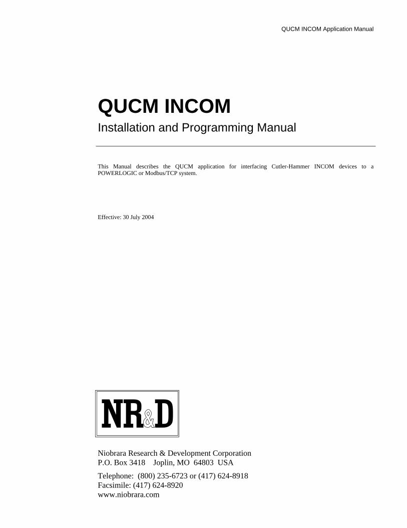
Figure 2-3 QUCM-LE to RS-232 PC DCE Port (9-pin) (MM1 Cable) .....................................11
Figure 2-4 ZAPREG32 COM1:9600,E,8,1 255 -B ......................................................................11
Figure 2-5 QLOAD the QUCM Firmware ...................................................................................13
Figure 2-6 FWLOAD the QUCM Firmware ................................................................................14
Figure 2-7 QLOAD of APP1 ........................................................................................................14
Figure 2-8 QLOAD of APP2 ........................................................................................................16
Figure 3-1 Main Web Page ...........................................................................................................38
Figure 3-2 Web Server Actual Data Page ....................................................................................39
Figure 3-3 Enter Password Page ...................................................................................................40
Figure 3-4 Configuration Page .....................................................................................................41
Figure 3-5 Add Device Page ........................................................................................................42
Figure 3-6 Serial Port Page ...........................................................................................................43
Figure 3-7 Statistics Web Page.....................................................................................................44
Figure 5-1 Network Example .......................................................................................................48
Figure 5-2 Example 1 Configuration Screen ................................................................................49
Figure 5-3 Dual IMPACC Network Example ..............................................................................50
Figure 5-4 Example 2 Configuration Screen ................................................................................51
Tables
Table 2-1 Universal RTD Register List ........................................................................................18
Table 2-2 IQ 1000 II Register List ...............................................................................................19
Table 2-3 IQ 1000 II Register List (Continued) ...........................................................................20
Table 2-4 IQ 1000 Register List ...................................................................................................21
Table 2-5 IQ 1000 Register List (Continued) ...............................................................................22
Table 2-6 Addressable Relay Register List ..................................................................................22
Table 2-7 Advantage Register List ...............................................................................................23
Table 2-8 Advantage Register List (continued) ...........................................................................24
Table 2-9 Analog Input Module Register List .............................................................................24
Table 2-10 Analog Input Module Register List (Continued) .......................................................25
Table 2-11 Analog Input Module Register List (Continued) .......................................................26
Table 2-12 Digitrip Register List .................................................................................................27
Table 2-13 Digitrip Register List (Continued)t ............................................................................28
Table 2-14 Digitrip Register List (Continued) .............................................................................29
Table 2-15 IQ Meter Register List ..............................................................................................30
Table 2-16 IQ Meter Register List (Continued)t ..........................................................................31
Table 6-1 Module Lights ..............................................................................................................53
Table 6-2 User Light Definitions .................................................................................................54
Table 0-1 IQ Meter Register List (Continued) .............................................................................33
Table 0-2 IQ Meter Register List (Continued) .............................................................................34

5
Table 0-3 IQ Meter Register List (Continued) .............................................................................35


QUCM INCOM Application Manual 1 Introduction 7
1
Introduction
The Niobrara QUCM is a TSX Quantum® compatible module that is capable of run-ning multiple applications for performing communication translations between serialprotocols. This document covers an application that places Cutler-Hammer® (West-inghouse®) IMPACC® devices on a Square D POWERLOGIC® network asPOWERLOGIC compatible devices. This setup allows existing C-H equipment to beintegrated into the POWERLOGIC System Manager Software system viaModbus/TCP Ethernet.
Two applications are required to be loaded into the QUCM: app1.qcm is the INCOMserial and Ethernet driver, app2.qcm is the and Modbus/TCP server and web serverused for configuration and data display. Both of these applications must be runningfor the system to properly perform.
Port 1 of the QUCM is to be connected to a C-H MINT II to provide the interface tothe INCOM network. Port 2 may also be configured as an INCOM Master and con-nected to a MINT II to provide a connection to a second INCOM network. INCOMdevices may also be connected over Ethernet through the C-H EPONI or EMINT. Upto 150 INCOM devices may be configured within the QUCM for access through port1, port 2, or Ethernet. The QUCM supports most C-H INCOM devices including IQmeters and Digitrip units. Support for direct and subnet access of INCOM devices isprovided. These devices are accessed via Modbus/TCP by selecting the DestinationIndex assigned to each slave (1-100 and 133-182).
Port 2 may be configured as a combination PNIM/Modbus RTU master to support astring of PowerLogic and/or Modbus RTU slaves. Up to 32 slaves may attached tothe QUCM. They must be assigned unique drop numbers between 1 and 32. Thesedevices are accessed by Modbus/TCP Destination Indices 101 through 132. In addi-tion to the combination PNIM/RTU mode, Port 2 may be configured for PNIM only,Modbus RTU only, PLOGIC only, and Modbus RTU Slave. PLOGIC mode uses theSY/MAX version of the POWERLOGIC protocol and should be used withPOWERLINK, CM100 CM200, and 810D units which experience a large number ofdropouts when using PNIM. The RTU Slave mode may be used for allowing a serialModbus RTU master to access the INCOM data.
Port 2 may also be configured to act as an INCOM slave from another INCOM net-work. In this configuration, the QUCM acts as an INCOM router allowing the trans-fer of commands from the network on Port 2 to the network on Port 1. Thus theQUCM may be inserted into an existing INCOM system and still keep the IMPACCserver. Port 2 must be connected directly to the RS-232 port of the IMPACC server. The IMPACC server must be configured for MINT operation on the RS-232 port. The

8 Introduction 1 QUCM INCOM Application Manual
timeout value on the IMPACC serial port should be increased to a minimum of5000mS.
The QUCM can also redirect EPONI communication from a PowerNet device serverto allow both PowerNet and SMS access to the EPONI device data. The EPONI unitsonly allow a single INCOM/TCP master which must be configured as the IP Addressof the QUCM. Additionally, the QUCM may be used to redirect INCOM/TCP mes-sages from a PowerNet Server to the EPONIs. Add the QUCM to the PowerNet sys-tem as an EMINT, then add the EPONI devices to the virtual EMINT by using theQUCM destination index as the device address of the slaves. The timeout value mustbe increased to at least 5000mS.
A Niobrara single slot rack with power supply (part number QXBP-001) is needed formounting the QUCM for stand-alone applications.
The SMS server is connected to the QUCM via Modbus/TCP Ethernet. The QUCM-SE will support up to 6 simultaneous Modbus/TCP clients for access to the INCOMdata and PowerLogic/Modbus data.

QUCM INCOM Application Manual 2 Installation 9
2
Installation
Module Installation1 Mount the QUCM in an available slot in the register rack. Secure the screw at the
bottom of the module.
Software InstallationThe application files for the QUCM are included in the INCOM.ZIP file. This filemust be unzipped using PKUNZIP.EXE. A copy of PKUNZIP is included on thestandard NR&D software disk and is also available at www.niobrara.com. The latestversion of the INCOM.ZIP file is located at
http://www.niobrara.com/ftp/qucm/incom/incom.zip
The latest version of this document in pdf format is located at:
http://www.niobrara.com/ftp/qucm/incom/incom.pdf
The IMPACC communications protocol is available from Cutler-Hammer at:
www.ch.cutler-hammer.com:2084/docs/fred/apscpgh/html/COMMUNIC/IL17384.HTM
Serial Connections to the QUCM-LE
QUCM to MINT II
Port 1 of the QUCM-LE must be set to RS-232. The Niobrara cable MM4 is ideal forthis connection since it includes an RJ45 RS-232 connection for the QUCM-LE and a25-pin male RS-232 modem pinout for the MINT II. This cable pinout is described inFigure 2-1
Figure 2-1 QUCM-LE to RS-232 DTE Port (25-pin) (MM4 Cable)
RJ45 DE25P (male)
3 2
4 3
5 7
6 4
7 5
6
8
20

10 Installation 2 QUCM INCOM Application Manual
The MINT II must be configured to match the serial settings of the QUCM Port 1. The supported baud rates by both units are 1200, 2400, 9600, and 19200. 19200 baudis recommended. The DIP switches on the front of the MINT II must be set for thefollowing:
• RS-232 Baud: 19200 (OFF, OFF)• INCOM Baud: set to match the INCOM network, typically 9600 baud (OFF)• STOP BITS: 1 (OFF)• MODEM CONTROL: NO RTS/CTS (ON)• ACK/NAK BYTE: SENT (OFF)• HANDSHAKE BYTE: NOT SENT (OFF)• SWITCH 8 (not used) (OFF)
The switches for the above configuration will be:
OFF, OFF, OFF, OFF, ON, OFF, OFF, OFF.
NOTE: The setting for the ACK/NAK byte is different than the UCM applications.
Figure 2-2 QUCM-LE Layout
Port 2 to the Personal Computer
A physical connection must be made from the personal computer to the QUCM in or-der to set the IP Address of the QUCM. This link may be a serial connection from aCOM port on the personal computer to the RS-232 port on the QUCM-LE. TheNiobrara MM1 cable may be used for this connection. This cable is shown in Figure2-3.
QUCM-LE
MM1 Cable
MINT II
INCOMNetwork
MM4 Cable
140QUCMNiobrara
ActiveReadyRun
ColLnkTXERXE
12345
RN1TX1RX1
6789
10RN2TX2RX2
Fault
QUCM INCOM Application Manual 2 Installation 11
Figure 2-3 QUCM-LE to RS-232 PC DCE Port (9-pin) (MM1 Cable)
Loading the Applications into the QUCMThe QUCM-LE or QUCM-OE must use the qucmtcpl.fwl or qucmtcpl.qcc firmwareincluded in the incom.zip file. This firmware is dated 15SEP2003 or later. There aretwo ways to upgrade the firmware of the QUCM-OE: QLOAD and FWLOAD.
Using ZAPREG32.EXE to set the IP Address
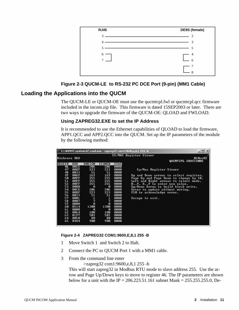
It is recommended to use the Ethernet capabilities of QLOAD to load the firmware,APP1.QCC and APP2.QCC into the QUCM. Set up the IP parameters of the moduleby the following method:
Figure 2-4 ZAPREG32 COM1:9600,E,8,1 255 -B
1 Move Switch 1 and Switch 2 to Halt.
2 Connect the PC to QUCM Port 1 with a MM1 cable.
3 From the command line enter>zapreg32 com1:9600,e,8,1 255 -b
This will start zapreg32 in Modbus RTU mode to slave address 255. Use the ar-row and Page Up/Down keys to move to register 46. The IP parameters are shownbelow for a unit with the IP = 206.223.51.161 subnet Mask = 255.255.255.0, De-
RJ45 DE9S (female)
3 2
4 3
5 5
6 4
7 6
7
8

12 Installation 2 QUCM INCOM Application Manual
fault Gate = 206.223.51.1, Modbus/TCP port number = 503: Register DescriptionExample (decimal)-------- ---------- ---------------------46 IP MSByte 20647 IP 22348 IP 5149 IP LSByte 16450 SN Mask 25551 SN Mask 25552 SN Mask 25553 SN Mask 054 Def. Gate 20655 Def. Gate 22356 Def. Gate 5157 Def. Gate 158 (leave this alone)59 (leave this alone)60 (leave this alone)61 (leave this alone)62 (leave this alone)63 Modbus Port 503 (this defaults to 502)
4 After entering the IP parameters, attempt to ping the module to verify the settings. > ping 206.223.51.164
5 Verify a connection to the internal Modbus/TCP server with zapreg32. > zapreg32 206.223.51.164:503 255
Should connect to the QUCM on port 503 with Destination index 255.
QLOAD QUCM Firmware Update
QLOAD is a convenient method for upgrading the firmware of a QUCM, especially ifthe QUCM already has an IP Address. A direct serial connection to the module is notrequired, the module does not need to be powered down, and the entire process maybe done remotely across the Ethernet.
1 Application 1 Switch must be in RUN.
2 Start QLOAD.EXE
3 Click on the Browse button and select the file qucmtcpl.qcc.
4 Select the Application 1 Radio Button.
5 Verify the following:
a. Status Register = 1.
b. Run Pointer Register = 33.
c. Auto Start is checked.
d. Erase Flash is checked.
e. Load File is checked.

QUCM INCOM Application Manual 2 Installation 13
f. The Modbus/TCP tab is selected.
(1) The IP Address of the QUCM is entered correctly.
(2) The TCP Port number is set to 503.
(3) The Modbus Drop is set to 255.
6 Press the Start Download button. QLOAD will open a progress window to showthe status of the download. Wait approximately 20 seconds for the upgrade to fin-ish after the download is complete. The unit should be ready to received the newversions of app1.qcc and app2.qcc.
Figure 2-5 QLOAD the QUCM Firmware
FWLOAD QUCM Firmware Update.
If the QUCM has corrupt firmware or completely non-responsive then the old methodof using FWLOAD may be required.
Firmware upload is as follows:
1 Remove the module form the rack.
2 Move the RUN/LOAD switch on the back of the module to LOAD.
3 Replace the module in the rack and apply power.
4 Only the 3 light should be on. (The Link and RX E-net lights may be on if theE-net port is connected and there is traffic.)
5 Connect the PC to QUCM Port 1 with a MM1 cable.. Make sure that Port 1 is setto RS232 mode with the slide switch below the port.
6 Start the program FWLOAD.EXE
7 Select the Browse button and select the file QUCMTCPL.FWL.
8 Select the comm port of the PC.
9 Press "Start Download".

14 Installation 2 QUCM INCOM Application Manual
10 When the download is completed, remove the module from the rack and changethe switch back to RUN.
Figure 2-6 FWLOAD the QUCM Firmware
QLOAD APP1 and APP2
Figure 2-7 QLOAD of APP1
1 Application 1 and 2 Switches must be in RUN.
2 Start QLOAD.EXE
3 Click on the Browse button and select the file app1.qcc.
4 Select the Application 1 Radio Button.
5 Verify the following:
a. Status Register = 1.
b. Run Pointer Register = 33.
c. Auto Start is checked.

QUCM INCOM Application Manual 2 Installation 15
d. Erase Flash is checked.
e. Load File is checked.
f. The Modbus/TCP tab is selected.
(1) The IP Address of the QUCM is entered correctly.
(2) The TCP Port number is set to 503.
(3) The Modbus Drop is set to 255.
6 Press the Start Download button. QLOAD will open a progress window to showthe status of the download.
7 Click on the Browse button and select the file app2.qcc.
8 Select the Application 2 Radio Button.
9 Verify the following:
a. Status Register = 3.
b. Run Pointer Register = 33.
c. Auto Start is checked.
d. Erase Flash is checked.
e. Load File is checked.
f. The Modbus/TCP tab is selected.
(1) The IP Address of the QUCM is entered correctly.
(2) The TCP Port number is set to 503.
(3) The Modbus Drop is set to 255.
10 Press the Start Download button. QLOAD will open a progress window to showthe status of the download.
After downloading both applications, the RN1 and RN2 lights should be on. Open aweb browser and point it to the IP Address of the QUCM for configuration.

16 Installation 2 QUCM INCOM Application Manual
Figure 2-8 QLOAD of APP2
INCOM InstallationThe following INCOM devices with their commands are supported by this QUCM ap-plication:
300 = Read Fast Status
301 = Read Fast Status for IQ Data Plus only
305 = Read Currents (A,B,C,G)
INCOM Device PLOGIC Device INCOM Commands
ABB MPS/NIM CM 2050 300, 353, 354
Addressable Relay Powerlogic Compatible
Advantage CM2050 300, 305
AEM II not mapped, must be set forAEM II mode.
300, 351
Digitrip RMS T700,T800
810D, Must be on AEMsubnet.
300, 305, 308, 3CA, 3CB, 3C8
Digitrip T810 810D 300, 305, 308, 309, 30A, 3CA, 3CB,3C8
Digitrip T910 810D 300, 305, 306, 308, 309, 30A, 3CA,3CB, 3C8
Digitrip 3000 810D 300, 305, 30F-N=2, 3CB
Digitrip MV 810D 300, 305
Digitrip Optim 550 810D 300, 305, 3C8, 3C9, 3CB
Digitrip Optim 750 810D 300, 305, 3C8, 3C9, 3CB
Digitrip Optim 1050 810D 300, 305, 308, 309, 3CA, 3C8, 3C9,3CB
Energy Sentinel CM2050 300, 308, 30A, 3C9
IQ Analyzer CM 2050 300, 305, 306, 307, 30F-N=6,30F-N=7, 30F-N=8, 30F-N=10,30F-N=11, 30F-N=12, 3C8, 3CD
IQ Data/Generator CM 2050 300, 305, 306, 307, 309, 3C9
IQ Data Plus CM2050 301, 35x
IQ Data Plus II/HV CM2050 300, 305, 306, 307, 308, 309, 30A, 3C9
IQ Data Plus 4000 CM2050 300, 305, 306, 307, 308, 309, 30F-N=8, 3C9
IQ 200 CM2050 300, 305, 306, 307, 308, 309, 30A, 3C9
IQ 500 810D 300, 305, 3C8
IQ 1000 810D 301, 38X
IQ 1000 II 810D 300, 305, 30F-N=1, 3C8
MPCV Relay CM2050 300, 305, 308, 309
Power Manager CM2050 300, 307, 308
Power Sentinel CM2050 300, 305, 306, 307, 308, 309, 30A, 3C9
Universal RTD POWERLOGIC Compatible 300, 30F-N=1

QUCM INCOM Application Manual 2 Installation 17
306 = Read L-L Voltages
307 = Read L-N Voltages
308 = Read Real, Demand Power
309 = Read Frequency, Reactive Power, Power Factor
30A = Read Energy
351 = Read IQDP Currents, L-L and L-N Voltages, Frequency, Real and ReactivePower, Power Factor, Energy
353 = Read ABB Status Data
354 = Read ABB Currents, L-L and L-N Voltages, Frequency, Real and ReactivePower,
Power Factor, Energy, Reactive Energy
3CA = Read Digitrip Total Real Energy, Forward Energy and Reverse Energy
3CB = Read Digitrip Trip Currents and Trip Energy
3C8 = Read Trip Status
3D1 = Process Subnet Command
Digitrip T700 and T800 units must be on an AEM II subnet. The AEM II must be setfor AEM II mode. IQ Data Plus II units are supported on AEM II subnets.
The present release of this application does not support writes from thePOWERLOGIC system.

18 Installation 2 QUCM INCOM Application Manual
Table 2-1 Universal RTD Register List
Modbus/TCPRegister
Description Notes
1 Device Status
2 Main Network Address
3 Subnet Address
4 Division Code
5 Comm Revision
6 - 29 Reserved
69 RTD Valid Bitmap Bits 0 through 9 are on when RTDvalid.
70 Winding Temperature 1
71 Winding Temperature 2
72 Winding Temperature 3
73 Winding Temperature 4
74 Winding Temperature 5
75 Winding Temperature 6
76 Motor Bearing 1 Temperature
77 Motor Bearing 2 Temperature
78 Load Bearing 1 Temperature
79 Load Bearing 2 Temperature
80 Aux. Temperature

QUCM INCOM Application Manual 2 Installation 19
Table 2-2 IQ 1000 II Register List
Modbus/TCPRegister
Description Notes
1 Device Status
2 Main Network Address
3 Subnet Address
4 Division Code
5 Comm Revision
6 Reserved
7, 1003 Current A
8, 1004 Current B
9, 1005 Current C
10, 1006 Current N
11, 1007 Current G
52 Trip Flags 1,2 b0 = Instantaneous Over Current Tripb1 = I-Squared T Tripb2 = Phase Unbalance Tripb3 = Ground Fault Tripb4 = Jam Tripb5 = Under Load Tripb6 = Trip Bypassb7 = Remote Hardware Input Tripb8 = Motor Bearing Temperature Tripb9 = Load Bearing Temperature Tripb10 = Winding Temperature Tripb11 = Reverse Sequence Tripb12 = Incomplete Sequence Tripb13 = A/D Converter Errorb14 = RAM Errorb15 = ROM Error
53 Trip Flags 3,4 b0 = Opto-coupler Failureb1 = Transition Not Completedb2 = Full Load Amps/CT Value Errorb3 = Battery Lowb4 = External Trip (Via INCOM)b5-b7 = Reservedb8 = Phase Unbalance Alarmb9 = Winding Temperature Alarmb10 = Motor Bearing Temperature Alarmb11 = Load Bearing Temperature Alarmb12-b15 = Reserved
54 Trip Flags 5,6 b0 = I-Squared T Alarm/Tripb1 = Starts per Hour Alarm/Tripb2-b15 = Reserved
55 Operations Count
56 Run Time
57 Remaining Starts
58 Oldest Start Time
59 Percent I2T
60 Highest Phase Current
61 Highest RTD Temperature
62 Number of I2T Trips

20 Installation 2 QUCM INCOM Application Manual
Table 2-3 IQ 1000 II Register List (Continued)
Modbus/TCPRegister
Description Notes
63 Number of Instantaneous OverCurrent Trips
64 Number of Under Load Trips
65 Number of Jam Trips
66 Number of Ground Fault Trips
67 Number of RTD Trips
68 Reserved
69 RTD Valid Bitmap Bits 0 through 9 are on when RTD valid.
70 Winding Temperature 1
71 Winding Temperature 2
72 Winding Temperature 3
73 Winding Temperature 4
74 Winding Temperature 5
75 Winding Temperature 6
76 Motor Bearing 1 Temperature
77 Motor Bearing 2 Temperature
78 Load Bearing 1 Temperature
79 Load Bearing 2 Temperature
80 Aux. Temperature

QUCM INCOM Application Manual 2 Installation 21
Table 2-4 IQ 1000 Register List
Modbus/TCPRegister
Description Notes
1 Device Status
2 Main Network Address
3 Subnet Address
4 Division Code
5 Comm Revision
6 Reserved
7, 1003 Current A
8, 1004 Current B
9, 1005 Current C
10, 11 Reserved
52 Trip Flags 1,2 b0 = Instantaneous Over Current Tripb1 = I-Squared T Tripb2 = Phase Unbalance Tripb3 = Ground Fault Tripb4 = Jam Tripb5 = Under Load Tripb6 = Trip Bypassb7 = Remote Hardware Input Tripb8 = Motor Bearing Temperature Tripb9 = Load Bearing Temperature Tripb10 = Winding Temperature Tripb11 = Reverse Sequence Tripb12 = Incomplete Sequence Tripb13 = A/D Converter Errorb14 = RAM Errorb15 = ROM Error
53 Trip Flags 3,4 b0 = Opto-coupler Failureb1 = Transition Not Completedb2 = Full Load Amps/CT Value Errorb3 = Battery Lowb4 = External Trip (Via INCOM)b5 = Differential Trip on AC Inputb6 = Ambient Temerature Tripb7 = Reservedb8 = Phase Unbalance Alarmb9 = Winding Temperature Alarmb10 = Motor Bearing Temperature Alarmb11 = Load Bearing Temperature Alarmb12 = Jam Alarmb13 = Under Load Alarmb14 = Ambient Temerature Alarmb15 = Reserved
54 Trip Flags 5,6 b0 = I-Squared T Alarm/Tripb1 = Starts per Hour Alarm/Tripb2-b15 = Reserved

22 Installation 2 QUCM INCOM Application Manual
Table 2-5 IQ 1000 Register List (Continued)
Table 2-6 Addressable Relay Register List
The Addressable Relay supports Modbus writes to register 7 only. Writing register 7will cause the QUCM to queue the double writes to the AR. After the QUCM acceptsthe Modbus write command, bit 0 of register 8 will come on to indicate that the writeis queued. After the QUCM sends the redundant writes to the AR, bit 0 of register 8will be cleared. The AR does not provide for a way of reading the relay to determinethe present state of the output relay so the value in register 7 is not guaranteed to re-flect the actual state of the relay. Common practice is to wire one of the AR’s inputsto the output to be able to read the state of the relay.
Modbus/TCPRegister
Description Notes
55 Operations Count
56 Run Time
57 Remaining Starts
58 Oldest Start Time
59 % of Full Scale Phase A Current
60 % of Full Scale Phase B Current
61 % of Full Scale Phase C Current
62-68 Reserved
69 RTD Valid Bitmap Bits 0 through 9 are on when RTD valid.
70 Winding Temperature 1
71 Winding Temperature 2
72 Winding Temperature 3
73 Winding Temperature 4
74 Winding Temperature 5
75 Winding Temperature 6
76 Motor Bearing 1 Temperature
77 Motor Bearing 2 Temperature
78 Load Bearing 1 Temperature
79 Load Bearing 2 Temperature
Modbus/TCPRegister
Description Notes
1 Device Status
2 Main Network Address
3 Subnet Address
4 Division Code
5 Comm Revision
6 Input Status b0 = Input 1 0=off, 1=onb1 = Input 2 0=off, 1=on
7 Output Command Set b0 to turn on relay, clear b0 to trun off relay
8 Command Status b0 is on while the write is pending, clears after the write wassent to the AR.

QUCM INCOM Application Manual 2 Installation 23
Table 2-7 Advantage Register List
Modbus/TCPRegister
Description Notes
1 Device Status
2 Main Network Address
3 Subnet Address
4 Division Code
5 Comm Revision
6 Reserved
7 Current A
8 Current B
9 Current C
10 Flags 1 b3 = Run/Closedb4 = Ready/Openb5 = Trip Indicationb7 = Overload
11 Flags 2 b1 = Run Permit Signal Presentb2 = Start Signal Presentb3 = Remote Reset Presentb7 = Local Reset Present
12 Flags 3 x01 = Overloadx02 = Ground Current Tripx03 = Phase Loss Tripx04 = Phase Unbalance Tripx10 = Ground Current Exceeds Interrupt Capactiyx20 = Control Voltage too low > Unit will openx30 = Control Voltage too low to pick upx40 = Control Voltage too high to pick upx50 = Current too low to closex70 = External Trip (via INCOM)
13 Coil Voltage
14 Maximum Coil Current on Closing
15 CHOLD Time equivalent fo the delay from the middle of each halfcycle to the beginning of holding pulse.
16 Coil_I
17 Dipheatre Setpoint b4-b0 = Heater number (0-31)b6. b5 00 = Class 10 Overload
01 = Class 20 Overlaod10 = Class 30 Overload11 = No protection
b7 = Automatic Reset
18 Econfig b0 = Ground Fault Enabledb1 = Phase Protection Enabledb2 = Thermal Overload Enabledb3 = 1=50Hz, 0=60Hzb4 = 1=overload, 0-contactor/starterb5 = Ultrasonic holding is enabledb6 = Local reset is disabledb7 = Unit will not reset thermal trip on power up even if resetconditions met

24 Installation 2 QUCM INCOM Application Manual
Table 2-8 Advantage Register List (continued)
Table 2-9 Analog Input Module Register List
Modbus/TCPRegister
Description Notes
19 Trip Time Offset
20 Current A at trip
21 Current B at trip
22 Current C at trip
54 Flags 1 at trip
55 Flags 2 at trip
56 Flags 3 at trip
Modbus/TCPRegister
Description Notes
1 Device Status
2 Main Network Address
3 Subnet Address
4 Division Code
5 Comm Revision
6 General Status b0 = Reservedb1 = Sensor Profile Errorb2 = N/Ab3 = Clock Errorb4 = Internal Communication Link Errorb5 = Memory Errorb6 = Checksum Errorb7-b15 = Reserved
7 Number of Sensors Configured 0-32
8 Sensor Hardware Error b0 = sensor 1, b15=sensor 16
9 Sensor Hardware Error b0 = sensor 17, b15=sensor 32
10 Sensor 1 Configuration b0-b3 = type 0 = no sensor1 = General Purpose2 = Pulse Contact3 = Runtime4, 5, 6, 7, 8 = N/A9 = BTU
11 Sensor 2 Configuration
12 Sensor 3 Configuration
13 Sensor 4 Configuration
14 Sensor 5 Configuration
15 Sensor 6 Configuration
16 Sensor 7 Configuration
17 Sensor 8 Configuration
18 Sensor 9 Configuration
19 Sensor 10 Configuration

QUCM INCOM Application Manual 2 Installation 25
Table 2-10 Analog Input Module Register List (Continued)
Modbus/TCPRegister
Description Notes
20 Sensor 11 Configuration
21 Sensor 12 Configuration
22 Sensor 13 Configuration
23 Sensor 14 Configuration
24 Sensor 15 Configuration
25 Sensor 16 Configuration
26 Sensor 17 Configuration
27 Sensor 18 Configuration
28 Sensor 19 Configuration
29 Sensor 20 Configuration
30 Sensor 21 Configuration
31 Sensor 22 Configuration
32 Sensor 23 Configuration
33 Sensor 24 Configuration
34 Sensor 25 Configuration
35 Sensor 26 Configuration
36 Sensor 27 Configuration
37 Sensor 28 Configuration
38 Sensor 29 Configuration
39 Sensor 30 Configuration
40 Sensor 31 Configuration
41 Sensor 32 Configuration
42 Reserved
43, 44 Sensor 01 Average Value (1 sec) or Running Total
45, 46 Sensor 02 Average Value (1 sec) or Running Total
47, 48 Sensor 03 Average Value (1 sec) or Running Total
49, 50 Sensor 04 Average Value (1 sec) or Running Total
51, 52 Sensor 05 Average Value (1 sec) or Running Total
53, 54 Sensor 06 Average Value (1 sec) or Running Total
55, 56 Sensor 07 Average Value (1 sec) or Running Total
57, 58 Sensor 08 Average Value (1 sec) or Running Total
59, 60 Sensor 09 Average Value (1 sec) or Running Total
61, 62 Sensor 10 Average Value (1 sec) or Running Total
63, 64 Sensor 11 Average Value (1 sec) or Running Total
65, 66 Sensor 12 Average Value (1 sec) or Running Total
67, 68 Sensor 13 Average Value (1 sec) or Running Total
69, 70 Sensor 14 Average Value (1 sec) or Running Total
71, 72 Sensor 15 Average Value (1 sec) or Running Total
73, 74 Sensor 16 Average Value (1 sec) or Running Total
75, 76 Sensor 17 Average Value (1 sec) or Running Total
77, 78 Sensor 18 Average Value (1 sec) or Running Total

26 Installation 2 QUCM INCOM Application Manual
Table 2-11 Analog Input Module Register List (Continued)
Modbus/TCPRegister
Description Notes
79, 80 Sensor 19 Average Value (1 sec) or Running Total
81, 82 Sensor 20 Average Value (1 sec) or Running Total
83, 84 Sensor 21 Average Value (1 sec) or Running Total
85, 86 Sensor 22 Average Value (1 sec) or Running Total
87, 88 Sensor 23 Average Value (1 sec) or Running Total
89, 90 Sensor 24 Average Value (1 sec) or Running Total
91, 92 Sensor 25 Average Value (1 sec) or Running Total
93, 94 Sensor 26 Average Value (1 sec) or Running Total
95, 96 Sensor 27 Average Value (1 sec) or Running Total
97, 98 Sensor 28 Average Value (1 sec) or Running Total
99, 100 Sensor 29 Average Value (1 sec) or Running Total
101, 102 Sensor 30 Average Value (1 sec) or Running Total
103 104 Sensor 31 Average Value (1 sec) or Running Total
105 106 Sensor 32 Average Value (1 sec) or Running Total

QUCM INCOM Application Manual 2 Installation 27
Table 2-12 Digitrip Register List
Modbus/TCPRegister
Description 700,800on
AEM
810on
AEM
910on
AEM
810Direct
910Direct
MV or3000
Optim550,750
Optim1050
1 Device Status X X X X X X X X
2 Main Network Address X X X X X X X X
3 Subnet Address X X X
4 Division Code X X X X X X X X
5 Comm Revision X X X X X X X X
6 Reserved
7, 1003 Current A X X X X X X X X
8, 1004 Current B X X X X X X X X
9, 1005 Current C X X X X X X X X
10, 1006 Current N
11, 1007 Current G X X X X X X X X
12, 1008 Current Avg C C C C C C C C
14, 1014 Voltage A-B X X
15, 1015 Voltage B-C X X
16, 1016 Voltage C-A X X
16, 1017 Voltage L-L Avg C C
21, 1034 True Power Factor Total X X X X X X
40, 2020 Scale A X X X X X X X X
41, 2021 Scale B X X X X X X X X
42, 2022 Scale C X X X X X X X X
43, 2023 Scale D X X X X X X X X
44, 2024 Scale E X X X X X X X X
45, 2025 Scale F X X X X X X X X

28 Installation 2 QUCM INCOM Application Manual
Table 2-13 Digitrip Register List (Continued)t
Modbus/TCPRegister
Description 700,800 onAEM
810 onAEM
910 onAEM
810Direct
910Direct
MV or3000
Optim550,750
Optim1050
50, 1601 Real Energy In (1) X X X
51, 1602 Real Energy In (2) X X X
52, 1603 Real Energy In (3) X X X
53, 1604 Real Energy In (4) X X X
54, 1609 Real Energy Out (1) X X X
55, 1610 Real Energy Out (2) X X X
56, 1611 Real Energy Out (3) X X X
57, 1612 Real Energy Out (4) X X X
26, 1621 Real Energy Total (1) X X X X X X
27, 1622 Real Energy Total (2) X X X X X X
28, 1623 Real Energy Total (3) X X X X X X
29, 1624 Real Energy Total (4) X X X X X X
25, 1734 Peak Demand Power X X X X X
80, 1827 Date/Time Energy Reset (1)
81, 1828 Date/Time Energy Reset (2)
82, 1829 Date/Time Energy Reset (3)
36, 2085 Sqare D ID X X X X X X X X
37, 8188 Square D ID X X X X X X X X
38, 3002 General Status X X X X X X X X
39, 3101 Cause of Trip X X X X X X X X
60, 3103 Date/Time of Trip (1) X X X
61, 3104 Date/Time of Trip (2) X X X
62, 3105 Date/Time of Trip (3) X X X
63, 3106 Current A at trip X X X X X X X X
64, 3107 Current B at trip X X X X X X X X
65, 3108 Current C at trip X X X X X X X X
66, 3109 Current N at trip
67, 3110 Current G at trip X X X X X X X X
68, 3111 Current Avg at trip C C C C C C C C
69, 3112 Real Power at trip X X X
70, 3129 Peak Demand Power at trip X X X X
71, 3113 Real Energy In at trip (1)
72, 3114 Real Energy In at trip (2)
73, 3115 Real Energy In at trip (3)
74, 3116 Real Energy In at trip (4)
75, 3117 Real Energy Out at trip (1)
76, 3118 Real Energy Out at trip (2)
77, 3119 Real Energy Out at trip (3)
78, 3120 Real Energy Out at trip (4)

QUCM INCOM Application Manual 2 Installation 29
Table 2-14 Digitrip Register List (Continued)
Modbus/TCPRegister
Description 700,800 onAEM
810 onAEM
910 onAEM
810Direct
910Direct
MV or3000
Optim550,750
Optim1050
79, 3121 Real Energy Signed at trip (1) X X X
80, 3122 Real Energy Signed at trip (2) X X X
81, 3123 Real Energy Signed at trip (3) X X X
82, 3124 Real Energy Signed at trip (4) X X X
85, 3201 Frame Type X X X X X X X X
86, 3203 Plug X X X X X X X X
87, 3204 Plug Rating X X X X X X X X
88 Event Count X
89 5 minute average of power X
90 Peak Demand Current A X
91 Peak Demand Current B X
92 Peak Demand Current C X
93 Peak Demand Current D X
200, 201 Real Energy (32-bit Integer) X X X X X X
202, 203 Real Energy IN(32-bit Integer) X X X
204, 205 Real Energy OUT (32-bit Integer) X X X

30 Installation 2 QUCM INCOM Application Manual
Table 2-15 IQ Meter Register List
Modbus/TCPRegister
Description IQ200
IQDataPlus
IQData
Plus II
IQDP4000
IQAnaly-
zer
IQDataGen.
IQEnergySent.
IQPowerSent.
PowerManager
1 Device Status X X X X X X X X X
2 Main Network Address X X X X X X X X X
3 Subnet Address X X X X X X X X X
4 Division Code X X X X X X X X X
5 Comm Revision X X X X X X X X X
6, 1001 Frequency X X X X X X X
7, 1003 Current A X X X X X X X
8, 1004 Current B X X X X X X X
9, 1005 Current C X X X X X X X
10, 1006 Current N
11, 1007 Current G X
12, 1008 Current Avg C C C C C C C
14, 1014 Voltage A-B X X X X X X X
15, 1015 Voltage B-C X X X X X X X
16, 1016 Voltage C-A X X X X X X X
17, 1017 Voltage L-L Avg C C C C C C C
18, 1018 Voltage A-N X X X X X X X X
19, 1019 Voltage B-N X X X X X X X X
20, 1020 Voltage C-N X X X X X X X X
83, 1011 Voltage L-N Avg C C C C C C C C
21, 1034 True Power Factor Total X X X X X
22, 1042 Real Power X X X X X X X X
23, 1046 Reactive Power X X X X X X
24, 1050 Apparent Power
25, 1731 Demand Power X X X X X
40, 2020 Scale A X X X X X X X X X
41, 2021 Scale B X X X X X X X X X
42, 2022 Scale C X X X X X X X X X
43, 2023 Scale D X X X X X X X X X
44, 2024 Scale E X X X X X X X X X
45, 2025 Scale F X X X X X X X X X
QUCM INCOM Application Manual 2 Installation 31
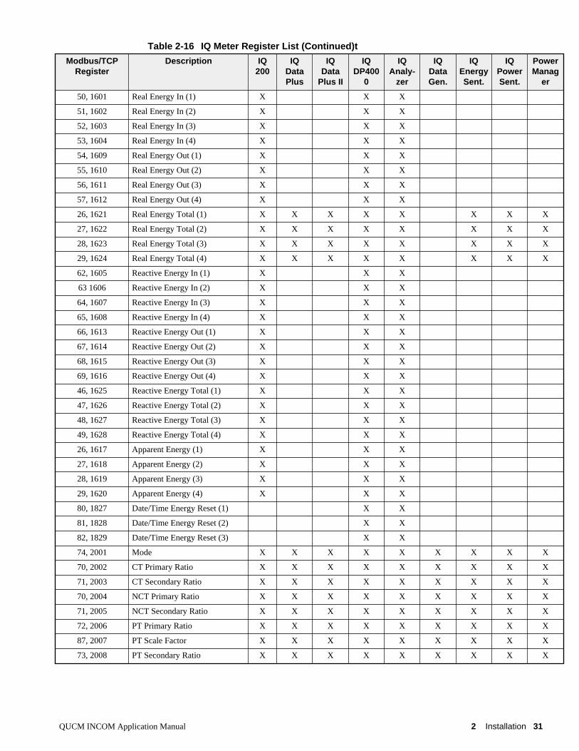
Table 2-16 IQ Meter Register List (Continued)t
Modbus/TCPRegister
Description IQ200
IQDataPlus
IQData
Plus II
IQDP400
0
IQAnaly-
zer
IQDataGen.
IQEnergySent.
IQPowerSent.
PowerManag
er
50, 1601 Real Energy In (1) X X X
51, 1602 Real Energy In (2) X X X
52, 1603 Real Energy In (3) X X X
53, 1604 Real Energy In (4) X X X
54, 1609 Real Energy Out (1) X X X
55, 1610 Real Energy Out (2) X X X
56, 1611 Real Energy Out (3) X X X
57, 1612 Real Energy Out (4) X X X
26, 1621 Real Energy Total (1) X X X X X X X X
27, 1622 Real Energy Total (2) X X X X X X X X
28, 1623 Real Energy Total (3) X X X X X X X X
29, 1624 Real Energy Total (4) X X X X X X X X
62, 1605 Reactive Energy In (1) X X X
63 1606 Reactive Energy In (2) X X X
64, 1607 Reactive Energy In (3) X X X
65, 1608 Reactive Energy In (4) X X X
66, 1613 Reactive Energy Out (1) X X X
67, 1614 Reactive Energy Out (2) X X X
68, 1615 Reactive Energy Out (3) X X X
69, 1616 Reactive Energy Out (4) X X X
46, 1625 Reactive Energy Total (1) X X X
47, 1626 Reactive Energy Total (2) X X X
48, 1627 Reactive Energy Total (3) X X X
49, 1628 Reactive Energy Total (4) X X X
26, 1617 Apparent Energy (1) X X X
27, 1618 Apparent Energy (2) X X X
28, 1619 Apparent Energy (3) X X X
29, 1620 Apparent Energy (4) X X X
80, 1827 Date/Time Energy Reset (1) X X
81, 1828 Date/Time Energy Reset (2) X X
82, 1829 Date/Time Energy Reset (3) X X
74, 2001 Mode X X X X X X X X X
70, 2002 CT Primary Ratio X X X X X X X X X
71, 2003 CT Secondary Ratio X X X X X X X X X
70, 2004 NCT Primary Ratio X X X X X X X X X
71, 2005 NCT Secondary Ratio X X X X X X X X X
72, 2006 PT Primary Ratio X X X X X X X X X
87, 2007 PT Scale Factor X X X X X X X X X
73, 2008 PT Secondary Ratio X X X X X X X X X

32 Installation 2 QUCM INCOM Application Manual

QUCM INCOM Application Manual 33
Table 0-1 IQ Meter Register List (Continued)
Modbus/TCPRegister
Description IQ200
IQDataPlus
IQData
Plus II
IQDP400
0
IQAnaly-
zer
IQDataGen.
IQEnerg
ySent.
IQPowerSent.
PowerManag
er
73, 2008 CT Ratio Correction Factor A X X X X X X X X X
84, 2009 CT Ratio Correction Factor B X X X X X X X X X
84, 2010 CT Ratio Correction Factor C X X X X X X X X X
84, 2011 CT Ratio Correction Factor N/G X X X X X X X X X
84, 2012 PT Ratio Correction Factor A X X X X X X X X X
84, 2013 PT Ratio Correction Factor B X X X X X X X X X
84, 2014 PT Ratio Correction Factor C X X X X X X X X X
85, 2015 Nominal System Frequency X X X X X X X X X
4, 2093 PLOS Rev. Sublevel X X X X X X X X X
49, 2400 Status In
36, 8085 Sqd ID 2085 X X X X X X X X X
37, 8188 Sqd ID 8188 X X X X X X X X X
38, 3002 General Status
39, 3101 Cause of Trip
130, 2094 Firmware X X X X X
130, 3401 Firmware Version X X X X X
117, 2404 Input Counter 1 X
118, 2405 Input Counter 1 X
119, 2409 Input Counter 2 X
120, 2410 Input Counter 2 X
121, 2414 Input Counter 3 X
122, 2415 Input Counter 3 X
141,2070 Demand Power Window X
142,1038 Displacement Power Factor X
143,1732 Demand Reactive Power X
144,1733 Demand Apparent Power X
145,1734 Demand Peak Real Power X
146,1738 Demand Peak Real Reactive X
147,1742 Demand Peak Apparent Power X
148,2079 Demand Current Window X
149,1700 Demand Current Total X
150,1708 Demand Peak Current Total X
151,1701 Demand Current A X
152,1702 Demand Current B X
153,1703 Demand Current C X
154,1709 Demand Peak Current A X
155,1710 Demand Peak Current B X
156,1711 Demand Peak Current C X

34 QUCM INCOM Application Manual
Table 0-2 IQ Meter Register List (Continued)
Modbus/TCPRegister
Description IQ200
IQDataPlus
IQData
Plus II
IQDP400
0
IQAnaly-
zer
IQDataGen.
IQEnerg
ySent.
IQPowerSent.
PowerManag
er
157,1039 Real Power A X
158,1040 Real Power B X
159,1041 Real Power C X
160,1043 Reactive Power A X
161,1044 Reactive Power B X
162,1045 Reactive Power C X
163,1047 Apparent Power A X
164,1048 Appaernt Power B X
165,1049 Apparent Power C X
166,1035 Displacement PF A X
167,1036 Displacement PF B X
168,1037 Displacement PF C X
169,1031 True PF A X
170,1032 True PF B X
171,1033 True PF C X
172-174,1872-1874
Peak Demand Current D/T X
175-177,1803-1805
Peak Demand Current D/T A X
178-180,1806-1808
Peak Demand Current D/T B X
181-183,1809-1811
Peak Demand Current D/T C X
184-186,1815-1817
Peak Demand Current Cleared D/T X
187-189,1812-1814
Peak Demand Real Power D/T X
190-192,1857-1859
Peak Demand Reactive Power X
193-195,1860-1862
Peak Demand App. Power D/T X
196-198,1824-1826
Peak Demand Power Cleared D/T X
200-201 KWH (32-bit Integer) X X X X X X X X
202-203 KWH IN (32-bit Integer) X X X
204-205 KWH OUT (32-bit Integer) X X X
206-207 KVARH (32-bit Integer) X X X
208-209 KVARH IN (32-bit Integer) X X X
210-211 KVARH OUT (32-bit Integer) X X X
212-213 KVAH (32-bit Integer) X X X

QUCM INCOM Application Manual 35
Table 0-3 IQ Meter Register List (Continued)
Modbus/TCPRegister
Description IQ200
IQDataPlus
IQData
Plus II
IQDP400
0
IQAnaly-
zer
IQDataGen.
IQEnerg
ySent.
IQPowerSent.
PowerManag
er
220,1051 THD Current A (% in 10ths) X
221,1052 THD Current B (% in 10ths) X
222,1053 THD Current C (% in 10ths) X
223,1054 THD Current N (% in 10ths) X
224,1055 THD Voltage A-N (% in 10ths) X
225,1056 THD Voltage B-N (% in 10ths) X
226,1057 THD Voltage C-N (% in 10ths) X
227,1058 THD Voltage A-B (% in 10ths) X
228,1059 THD Voltage B-C (% in 10ths) X
229,1060 THD Voltage C-A (% in 10ths) X


QUCM INCOM Application Manual 3 WEB Server 37
3
WEB Server
Main PageThe Main page displays a summary of the configured INCOM devices. The table willdisplay the Modbus/TCP Destination Index, Device Type (if known), CommunicationRevision of the slave, Main INCOM network address, Subnet INCOM network ad-dress, and Device Status. If a device is not responding to queries from the QUCMthen the Status table entry will have a gray background and display the text "Offline". If the device is responding to queries then the cell will display "Online" along with ashort description of the status of the device. The Online message is a hypertext linkthat will display the "Actual" data for that device.
Figure 3-1 shows an example page with Port 2 set for INCOM Slave mode with an IQData Plus II 003 online. Devices 2 and 3 have been configured but they have yet torespond to a query from the QUCM so their device type is unknown. Device 4 is anIQ DP-4000 meter which is presently configured as "Out of Service". At some pointin the past, the QUCM has communicated with device 4 because it knows that it wasan IQ DP-4000.
At the bottom of the Main page are links to Niobrara’s WWW site, Statistics on thisQUCM, and a page for configuring this QUCM.

38 WEB Server 3 QUCM INCOM Application Manual
Figure 3-1 Main Web Page
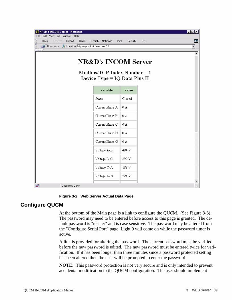
Actual Data PageFollowing one of the "Online" links will display a table of the metered data for theparticular INCOM device. Figure 3-2 shows a table for an IQ Data Plus II meter withno current flowing.
QUCM INCOM Application Manual 3 WEB Server 39
Figure 3-2 Web Server Actual Data Page
Configure QUCMAt the bottom of the Main page is a link to configure the QUCM. (See Figure 3-3). The password may need to be entered before access to this page is granted. The de-fault password is "master" and is case sensitive. The password may be altered fromthe "Configure Serial Port" page. Light 9 will come on while the password timer isactive.
A link is provided for altering the password. The current password must be verifiedbefore the new password is edited. The new password must be entered twice for veri-fication. If it has been longer than three minutes since a password protected settinghas been altered then the user will be prompted to enter the password.
NOTE: This password protection is not very secure and is only intended to preventaccidental modification to the QUCM configuration. The user should implement

40 WEB Server 3 QUCM INCOM Application Manual
other more stringent protection such as firewalls and isolated networks to ensure thesafety of the metered system.
NOTE: Once a password has been accepted by the QUCM, any connection is al-lowed to modify settings until the timer expires; not just the user who entered thepassword.
Figure 3-3 Enter Password Page
After entering a successful passoword a screen like Figure 3-4 is displayed. EachINCOM device configured is shown with a link to edit the device paramters or removethe device. Links below are given to add a new device, alter the serial port configura-tion, change the password, and save the configuration to FLASH.

QUCM INCOM Application Manual 3 WEB Server 41
Figure 3-4 Configuration Page
Add Device
The Add Device link is used to add a new INCOM device to the list. A screen likeFigure is displayed. There is a pull-down menu item for the Modbus/TCP DestinationIndex. This menu will only display unused values.
There is a text field for the Main INCOM Network Address. This value is entered inhexadecimal. If the target device is on the main network then simply enter its threedigit address. This is usually the rotary switches on the PONI. If the device is on asub-network (such as off of an AEM) then enter the main network address of theAEM.
There is a pull-down menu for the Subnet address. If the device is on the Main net-work then set this value to 000. Otherwise enter the address of the device.
There are boxes for the IP Address of an EPONI. Set the IP Address to 0.0.0.0 if theINCOM device is connected to a QUCM serial Port though a MINT II. Otherwiseenter the IP Address of the EPONI.

42 WEB Server 3 QUCM INCOM Application Manual
There is a check box for "In Service". Clearing this check box keeps the device in theQUCM’s configuration but prohibits the QUCM from actually polling it. This may bedesirable if a particular device is to be powered off for extended periods of time be-cause the QUCM will not waste bandwidth trying to poll a device that is not present.
Figure 3-5 Add Device Page
Serial Port Configuration
The Serial Port Configuration page allows the altering of the baud rates of QUCMport 1 and 2, the Protocol of Port 2, and the Parity of Port 2.
Port 1 is fixed as an INCOM Master. Its parity is fixed at NONE. Its baud rate maybe set to 1200, 2400, 9600, or 19200. 19200 is recommended.
Port 2 may be set to INCOM Slave, PNIM/RTU Master, PNIM Master, RTU Master,PLOGIC Master, and RTU Slave. As an INCOM Slave its parity is fixed at NONEand its baud rates may be set to 1200, 2400, 9600, or 19200. As aPNIM/RTU/PLOGIC Master or Slave, its parity may be set to EVEN or NONE and itsbaud rate may be set to 1200, 2400, 4800, 9600, or 19200
When Port 2 is in PNIM/RTU/PLOGIC, it accepts Modbus/TCP queries to Destina-tion Idices 101 through 132 and passes the messages out to either PNIM, PLOGIC, orModbus RTU slaves 1 through 32. The QUCM will automatically determine theproper protocol for the each of the possible 32 slaves.

QUCM INCOM Application Manual 3 WEB Server 43
Modbus RTU Slave mode allows a serial Modbus Master to read the data from Incomslaves 1 through 100.
Figure 3-6 Serial Port Page
Save Settings to FLASH
After completion of the configuration, be sure to save the settings to flash. Otherwisethe modifications will be lost on the next power cycle of the QUCM. Once the set-tings are saved to flash, the QUCM’s configuration, including its IP settings, will besafe indefinately.
Statistics PageAt the bottom of the Main page is a link to some statistical information about thisQUCM. (See Figure 3-7)

44 WEB Server 3 QUCM INCOM Application Manual
Figure 3-7 Statistics Web Page
QUCM INCOM Application Manual 4 FTP Server 45
4
FTP Server
Application 2 contains an FTP server as well as the web server. The FTP server al-lows the storage and retrieval of the FLASH setup parameters used by Application 1and 2 from any computer with an FTP client. The user flash areas are presented bythe QUCM’s FTP server as a single file called "flash.bin". The user may use "get" toretrieve this file from the QUCM and "put" or "send" to copy this file to the QUCM. At this time, the login name is not required and the password is the same as the Webserver password (defaults to "master"). When the file is copied to the QUCM (usingput or send), the QUCM is rebooted after the FTP session is "quit" to allow the mod-ule to restart and load the new settings from FLASH.
Example Login, DIR, and "get"
>ftp 206.223.51.163Connected to 206.223.51.163.220 QUCM FTP Service (Version 07Jul2000)User (206.223.51.163):(none)):331 User okay; need password.password:230 User logged in; proceed.ftp> dir200 PORT Command Successful.150 Opening ASCII mode data connection for /bin/ls.flash.bin226 PORT Command Successful.11 bytes received in 0.01 seconds (1.10 Kbytes/sec)ftp> get flash.bin200 PORT Command Successful.150 Opening ASCII mode data connection for flash.bin(16384 bytes).226 Transfer complete.16384 bytes received in 2.72 seconds (6.01 Kbytes/sec)ftp> quit221 Connection Closing. goodbye.


QUCM INCOM Application Manual 5 Examples 47
5
Examples
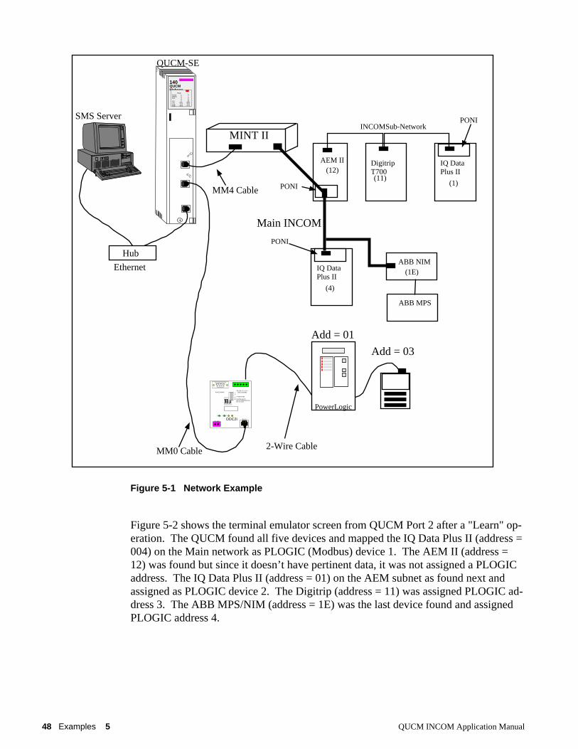
Example 1Figure 5-1 displays an example INCOM network with a QUCM-SE, MINT II, anAEM II (address = 012) with a sub-network consisting of an IQ Data Plus II (address= 001) and a Digitrip T700 (address = 011). Also on the main network is another IQData Plus II (address 004) and an ABB MPS/NIM (address = 01E).
Port 2 of the QUCM is configured for PNIM/RTU mode at 9600 baud, EVEN parit. A Niobrara DDC2I RS-232<>RS-485 converter is connected to the QUCM portthrough an MM0 cable. The DDC2I’s RS-485 port has a network with a CM-2350and a Modicon Momentum PLC connected. The CM is set to drop 1 in PNIM modewhile the PLC speaks Modbus RTU at drop 2. The CM may be reached byModbus/TCP Index 101 and the PLC by Index 102.
48 Examples 5 QUCM INCOM Application Manual
Figure 5-1 Network Example
Figure 5-2 shows the terminal emulator screen from QUCM Port 2 after a "Learn" op-eration. The QUCM found all five devices and mapped the IQ Data Plus II (address =004) on the Main network as PLOGIC (Modbus) device 1. The AEM II (address =12) was found but since it doesn’t have pertinent data, it was not assigned a PLOGICaddress. The IQ Data Plus II (address = 01) on the AEM subnet as found next andassigned as PLOGIC device 2. The Digitrip (address = 11) was assigned PLOGIC ad-dress 3. The ABB MPS/NIM (address = 1E) was the last device found and assignedPLOGIC address 4.
Digitrip IQ Data
Main INCOM
INCOMSub-Network
(12)(11)
(1)
T700 Plus II
AEM II
PONI
IQ Data
(4)
Plus II
PONI
(1E)ABB NIM
ABB MPS
QUCM-SE
MINT II
MM4 Cable PONI
SMS Server
140QUCMNiobrara
ActiveReadyRun
ColLnkTXERXE
12345
RN1TX1RX1
6789
10RN2TX2RX2
Fault
Hub
Ethernet
MM0 Cable
PowerLogic
DDC2IPower RxTxTxEN
RS422/RS485Rx- Rx+ Tx- Tx+
RS422/RS485
9V-24V- +
RS2325V IN
4 WIRE/2WIRE
MASTER/SLAVEOFF/ON TERMINATIONOFF/ON BIAS
2-Wire Cable
Add = 01
Add = 03

QUCM INCOM Application Manual 5 Examples 49
Figure 5-2 Example 1 Configuration Screen
Incoming Modbus/TCP messages with a Destination Index (target drop) of 1 will besent to the IQ Data Plus II (address = 04), Index 2 will be sent to the IQ Data Plus II(address 01), Index 3 will be sent to the Digitrip, and Index 4 will be sent to the ABB.
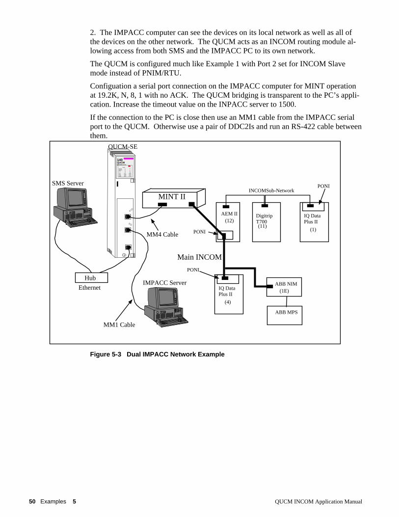
Example 2Figure 5-3 displays an example INCOM network with a QUCM-SE, MINT II, anAEM II (address = 012) with a sub-network consisting of an IQ Data Plus II (address= 001) and a Digitrip T700 (address = 011). Also on the main network is another IQData Plus II (address 004) and an ABB MPS/NIM (address = 01E).
Port 2 of the QUCM is connected to a PC running IMPACC III software.
This example allows the SMS computer to see all of the data on the INCOM networkattached to QUCM Port 1 but not the devices on the network attached to QUCM Port
50 Examples 5 QUCM INCOM Application Manual
2. The IMPACC computer can see the devices on its local network as well as all ofthe devices on the other network. The QUCM acts as an INCOM routing module al-lowing access from both SMS and the IMPACC PC to its own network.
The QUCM is configured much like Example 1 with Port 2 set for INCOM Slavemode instead of PNIM/RTU.
Configuation a serial port connection on the IMPACC computer for MINT operationat 19.2K, N, 8, 1 with no ACK. The QUCM bridging is transparent to the PC’s appli-cation. Increase the timeout value on the INPACC server to 1500.
If the connection to the PC is close then use an MM1 cable from the IMPACC serialport to the QUCM. Otherwise use a pair of DDC2Is and run an RS-422 cable betweenthem.
Figure 5-3 Dual IMPACC Network Example
Digitrip IQ Data
Main INCOM
INCOMSub-Network
(12)(11)
(1)
T700 Plus II
AEM II
PONI
IQ Data
(4)
Plus II
PONI
(1E)ABB NIM
ABB MPS
QUCM-SE
MINT II
MM4 Cable PONI
SMS Server
140QUCMNiobrara
ActiveReadyRun
ColLnkTXERXE
12345
RN1TX1RX1
6789
10RN2TX2RX2
Fault
Hub
EthernetIMPACC Server
MM1 Cable

QUCM INCOM Application Manual 5 Examples 51
Figure 5-4 Example 2 Configuration Screen
Incoming Modbus/TCP messages with a Destination Index (target drop) of 1 will besent to the IQ Data Plus II (address = 04), Index 2 will be sent to the IQ Data Plus II(address 01), Index 3 will be sent to the Digitrip, and Index 4 will be sent to the ABB.


QUCM INCOM Application Manual 6 Troubleshooting 53
6
Troubleshooting
Module LightsThe QUCM-SE has several lights that indicate the status of the module. Table 6-1shows the meanings of these lights.
Table 6-1 Module Lights
User LightsThe QUCM-SE has 10 application driven lights numbered 1-10. The meaning ofthese lights while the APP1 program is running is shown in Table 6-2.
Light Meaning
Fault The module has a catastrophic fault.. Call the factory.
Active This light will be on if the module is in a traffic-copped slot in a Quantum PLCsystem and the PLC is in RUN.
Ready This light should always be on (as long as it isn’t in firmware load).
Run This light will be on if the module is in a traffic-copped slot in a Quantum PLCsystem and the PLC is in RUN.
Col Comes on when an Ethernet collision occurs.
Lnk Is on when LINK is established on the 10BaseT port.
TXE Comes on when the module is transmitting on the Ethernet port.
RXE Comes on when the module is receiving on the Ethernet port.
RN1 This light should be on to indicate app1 is running.
TX1 Comes on when the module is transmitting on serial port 1.
RX2 Comes on when the module is receiving on serial port 1.
RN2 This light should not come on since there is no app2 loaded.
TX1 Comes on when the module is transmitting on serial port 1.
RX2 Comes on when the module is receiving on serial port 1.

54 Troubleshooting 6 QUCM INCOM Application Manual
Table 6-2 User Light Definitions
Light Meaning
1 INCOM network not configured if rapidly blinking (5/sec).No ACK from MINT if slowly blinking (1/sec).
2 INCOM Reply Timeout (1/sec).
3 INCOM Bad Checksum (1/sec).
4 INCOM BCH Error (1/sec).
5 INCOM Error Bit Set in Reply (1/sec).
6 Port 2 Terminal Server Running when ON.
7 Learn Mode when ON.
8 At Least One Modbus/TCP Server Connection Open when ON.
9 TELNET Server Running when ON.
10 Port 2 in Modbus (and SY/MAX) Slave mode when ON.


