QUASI-STATIC INDENTATION BEHAVIOR OF GFRP WITH MILLED ...
19
FACTA UNIVERSITATIS Series: Mechanical Engineering Vol. 17, N o 3, 2019, pp. 425 - 443 https://doi.org/10.22190/FUME181204004S © 2019 by University of Niš, Serbia | Creative Commons License: CC BY-NC-ND Original scientific paper QUASI-STATIC INDENTATION BEHAVIOR OF GFRP WITH MILLED GLASS FIBER FILLER MONITORED BY ACOUSTIC EMISSION Kannivel Saravanakumar 1 , Balakrishnan Sai Lakshminarayanan 1 , Vellayaraj Arumugam 1 , Carlo Santulli 2 , Ana Pavlovic 3 , Cristiano Fragassa 3 1 Department of Aerospace Engineering, MIT campus, Chromepet, Anna University, India 2 School of Architecture and Design, Università of Camerino, Ascoli Piceno, Italy 3 Department of Industrial Engineering, University of Bologna, Bologna, Italy Abstract. This paper aims at investigating the influence of the addition of milled glass fibers upon quasi-static indentation (QSI) properties of glass/epoxy composite laminates. The QSI behavior was experimentally studied by evaluating indentation force, residual dent depth, energy absorbed and size of the damaged area for different indentation depths. Following the QSI tests, the filler-loaded glass/epoxy samples were subjected to three-point bending tests in order to measure residual flexural strength, and the results were compared with the baseline glass/epoxy samples. Both tests were performed with online acoustic emission monitoring in order to observe damage progression and characterize different fracture mechanisms associated with loading. The results show that the filler-loaded laminates exhibit a substantial improvement in the peak force and contact stiffness, with a reduced permanent damage both in terms of depth and of area, in comparison with the baseline ones. It is found that the filler presence offers greater stiffness and higher energy dissipation through toughening mechanisms such as filler debonding/pullout and filler bridging/interlocking. Key Words: Glass/Epoxy, Delamination, Quasi-Static Indentation (QSI), Residual Flexural Strength, Acoustic Emission Received December 04, 2018 / Accepted February 03, 2019 Corresponding author: Cristiano Fragassa Department of Industrial Engineering, Alma Mater Studiorum University of Bologna, viale Risorgimento 2, 40136, Bologna, Italy E-mail: [email protected]
Transcript of QUASI-STATIC INDENTATION BEHAVIOR OF GFRP WITH MILLED ...

FACTA UNIVERSITATIS
Series: Mechanical Engineering Vol. 17, No 3, 2019, pp. 425 - 443
https://doi.org/10.22190/FUME181204004S
© 2019 by University of Niš, Serbia | Creative Commons License: CC BY-NC-ND
Original scientific paper
QUASI-STATIC INDENTATION BEHAVIOR
OF GFRP WITH MILLED GLASS FIBER FILLER
MONITORED BY ACOUSTIC EMISSION
Kannivel Saravanakumar1, Balakrishnan Sai Lakshminarayanan
1,
Vellayaraj Arumugam1, Carlo Santulli
2, Ana Pavlovic
3,
Cristiano Fragassa3
1Department of Aerospace Engineering, MIT campus, Chromepet, Anna University, India 2School of Architecture and Design, Università of Camerino, Ascoli Piceno, Italy
3Department of Industrial Engineering, University of Bologna, Bologna, Italy
Abstract. This paper aims at investigating the influence of the addition of milled glass
fibers upon quasi-static indentation (QSI) properties of glass/epoxy composite laminates.
The QSI behavior was experimentally studied by evaluating indentation force, residual
dent depth, energy absorbed and size of the damaged area for different indentation
depths. Following the QSI tests, the filler-loaded glass/epoxy samples were subjected to
three-point bending tests in order to measure residual flexural strength, and the results
were compared with the baseline glass/epoxy samples. Both tests were performed with
online acoustic emission monitoring in order to observe damage progression and
characterize different fracture mechanisms associated with loading. The results show that
the filler-loaded laminates exhibit a substantial improvement in the peak force and
contact stiffness, with a reduced permanent damage both in terms of depth and of area, in
comparison with the baseline ones. It is found that the filler presence offers greater
stiffness and higher energy dissipation through toughening mechanisms such as filler
debonding/pullout and filler bridging/interlocking.
Key Words: Glass/Epoxy, Delamination, Quasi-Static Indentation (QSI),
Residual Flexural Strength, Acoustic Emission
Received December 04, 2018 / Accepted February 03, 2019
Corresponding author: Cristiano Fragassa
Department of Industrial Engineering, Alma Mater Studiorum University of Bologna, viale Risorgimento 2,
40136, Bologna, Italy
E-mail: [email protected]

426 K. SARAVANAKUMAR, B.S. LAKSHMINARAYANAN, V.ARUMUGAM, et al.
1. INTRODUCTION
Fiber-reinforced composites, made of glass, carbon or even natural fibers, have
found their application in several industries such as aerospace, automobile, marine, wind
turbines production, etc., due to their high specific stiffness/strength, chemical resistance
and fatigue properties, which makes them a suitable alternative for metals [1-3]. On the
other side, the composites are susceptible to delamination due to poor mechanical
properties through their thickness [4]. This effect is evident, in particular, when adhesion
between the fibers and the matrixes is not initially perfect or has deteriorated with use
[5]. Especially in the case of low velocity impacts [6] due to external objects, tool drop
during service/maintenance, runway debris and other accidental events, etc., localized
damage can result in drastic reduction in strength/stiffness and is likely to expand during
service. It is noticed that the damage induced in low-velocity impact can be effectively
simulated in quasi-static indentation tests regarding their advantage in providing longer
times, hence enabling damage evolution monitoring [7, 8]. In practice, the quasi-static
indentation tests supply information about contact behavior between the sample and the
indenter as well as on the occurrence of sequential damage with varying indenter
displacement/depth. Abdallah and Bouver [9] experimentally investigated the damage
behavior and effects of permanent indentation on highly oriented composites plates.
They observed that the peak force experienced during low velocity impact was higher
than in the case of the quasi-static test. However, damage morphology and absorbed
energy were equivalent for both tests.
Various works [10, 11] have established correlations between quasi-static indentation
and dynamic falling weight impact tests. The damage initiation and propagation were
investigated comprehensively by controlling peak force and deformation. The parameters,
such as peak load or ultimate load, incident energy, absorbed energy, elastic energy and
residual depth, were determined in order to quantify the local damage in the composite
materials during quasi-static indentation tests [12, 13]. Arabzadeh and Zeinoiddini [14]
studied quasi-static indentation response of flexibly supported pressurized pipes,
suggesting a closed-form relationship between indentation force and dent depth by
considering different boundary conditions, such as internal pressure soil stiffness and
embedment between soil and pipe into their modeling. They observed that the influence
of the surrounding soil was prominent when the fluid pressure inside the pipe is very
low. Sutherland and Guedes Soares [15] investigated the quasi-static indentation behavior
of E-glass/polyester marine laminates observing that the chopped strand mat laminates
exhibited better contact stiffness than the woven roving ones. They also report that the
large global deflection in thinner samples leads to a larger contact area due to the wrapping
of laminate around the indenter. In quasi-static punch shear tests on quasi-isotropic
carbon/epoxy, a good correlation between load-displacement response and finite element
modeling was reported, indicating that a slope change or a load drop indicates delamination
initiation, which propagates through subsequent oscillations: further damage was produced
by plug formation exit from the plate [16].
The progressive penetration mechanism of ultra-high molecular weight polyethylene
reinforced cross-ply composite laminates was investigated by O’Masta et al. [17]. They
observed that sample penetration occurred by tensile ply rupture under the projectile,
and higher penetration resistance and onset velocity occurred as the consequence of the
sample being end-supported rather than back-supported. The effect of hybridization on

Quasi-Static Indentation Behavior of GFRP with Milled Glass Fiber Filler Monitored by Acoustic... 427
impact and post-impact performance of the composite laminates was investigated by
Suresh Kumar et al. [18]. The low-velocity impact behavior was simulated by quasi-
static indentation (QSI) tests on quasi-isotropic glass/epoxy, glass/basalt/epoxy (G/B/G,
B/G/B) and glass/carbon/epoxy (G/C/G, C/G/C) laminates with acoustic emission
monitoring. Addition of basalt fiber and carbon fiber to glass fiber improved indentation
damage resistance, while AE monitoring was reported to be a sensitive method to
characterize damage evolution in the laminates.
The conventional composite laminates fabricated with thermoset matrix, such as epoxy,
suffer from low impact damage resistance, poor fiber/matrix interface bond strength, low
fracture toughness, and poor transverse mechanical properties. Their delamination resistance
can be enhanced by incorporating micro/nano-sized fillers into the matrix. Toughening
mechanisms, such as cavitation, crack pinning, crack deflection, and crack bridging were
observed to have improved interlaminar fracture toughness of the composites [19-21].
Acoustic emission monitoring can be effectively used for monitoring/tracking the
damage evolution and for identifying/characterizing failure modes in the fiber-
reinforced composites laminates during loading [22-24]. Each acquired AE signal bears
some relation with the damage mechanisms, in that it is associated with the specific
amount of strain energy released during failure. It has been reported that the failure
modes can be identified based on the signal-based approach utilizing AE waveforms,
fast Fourier transform (FFT) and short time fast Fourier transform (STFFT), while the
parametric-based approach uses AE parameters, such as counts, energy, rise time, RMS,
signal strength and duration, etc., [25, 26]. Bussiba et al. [27] employed STFFT analysis
to discriminate different failure modes and studied sequential damage evolution in
composite laminates. Ramirez-Jimenez et al. [28] discriminated damage mechanisms,
such as matrix crack, debonding, delamination, and fiber breakage based on the peak
frequency analysis. Arumugam et al. [29] investigated the classification of failure modes
for different ply orientation sequences, based on the frequency content of AE signals.
This work focuses on investigating the effect of introducing a limited amount of
milled glass fiber fillers upon the quasi static indentation behavior and residual
performance of glass/epoxy laminates. The damage initiation, progression, and failure
mechanism associated with quasi-static indentation and three-point bending test were
also discussed with online AE monitoring. The glass/epoxy samples were subjected to
quasi-static indentation test at different indentation depths (1 to 6 mm). The indentation
test parameters in terms of peak force and absorbed energy, as well as residual
(permanent) dent depth and damage area were evaluated, and the results were correlated
with those from the baseline samples. The residual strength of the samples was also
estimated in order to determine damage tolerance of the composite laminates.
2. EXPERIMENTAL PROCEDURE
2.1. Materials and fabrication of composite laminates
The glass/epoxy composite laminates were fabricated by hand lay-up technique with
a cross-ply stacking sequence of [0º/90º]4s configuration. Unidirectional 220 g/m² glass
fabric and LY556 epoxy resin with HY951 hardener were used as raw materials and
taken in the ratio of 1:1 by weight for fabricating the laminates. Milled glass fibers were

428 K. SARAVANAKUMAR, B.S. LAKSHMINARAYANAN, V.ARUMUGAM, et al.
added to the epoxy resin (in a ratio of 5:100 by weight) through sonication and mechanical
stirring to distribute them uniformly in the resin. The mixture was then degassed in order to
remove entrapped air bubbles. The hardener was added to the mixture at a ratio of 1:10 by
weight and further stirred to initiate the curing process. The mixture was then evenly
distributed on the glass fabric with the aid of brush and roller to improve fiber impregnation.
Correspondingly, baseline glass/epoxy laminates without milled glass fibers were fabricated
as above. The laminates, with dimensions of 500 x 500 mm, and nominal thickness of 4.5
(±0.25) mm, were allowed to cure at room temperature for 24 hours; then the samples were
cut from them using abrasive water-jet cutting machine. Also filler-loaded samples had the
same objective thickness of 4.5 mm, and their weight was in excess with respect to the
baseline ones by no more than around 2%, therefore basically included in the experimental
error.
2.2. Quasi-Static Indentation test
Quasi-static indentation tests were performed on the Tinius Olsen 100kN Universal
Testing Machine at crosshead speed of 1 mm/min. The test was carried out with the
indentation fixture as per ASTM D6264/D6264M-17 standard [30], hence with a
hemispherical indenter. The glass/epoxy samples with dimensions of 150 x 100 mm rested
on the fixture and were clamped at both sides, as shown in Fig. 1. Later, the indentation test
was performed directly on the center of the samples. The specimen was indented with a
12.7 mm diameter hemispherical end steel tup. Load-displacement data were recorded via
the digital data acquisition system from the universal testing machine. Four specimens were
tested in all the cases, and the average results were considered. QSI tests were carried out at
a predetermined indentation depth of 1, 2, 3, 4, 5 and 6 mm, respectively. Quasi-static
indentation behavior and test parameters, such as indentation force, residual dent depth,
energy absorbed, contact stiffness and damaged area at different indentation depths were
evaluated. The evolution of damage and damage mechanism associated with indentation
were monitored with online AE monitoring.
Fig. 1 Quasi-Static Indentation test fixture

Quasi-Static Indentation Behavior of GFRP with Milled Glass Fiber Filler Monitored by Acoustic... 429
2.3. Three-point bending test
Post-indentation flexural tests were performed on glass/epoxy samples, trimmed to a
dimension of 150x50 mm using a diamond saw, with three-point bending fixture under
displacement control regime. Care was taken to ensure not to damage the indented zone
during cutting, according to previous indications supplied by [31-33]. The tests were
carried out at a constant cross-head speed of 1 mm/min. The span length was kept equal
to 100 mm, and four repetitions were performed for each category of samples. The residual
flexural strength was determined from the test, and the results were correlated with the
non-indented baseline and filler-loaded samples.
2.4. Acoustic emission monitoring of QSI and FAI
Acoustic emission monitoring was employed during quasi-static indentation tests and
flexural after indentation tests. An eight-channel AE system supplied by the Physical
Acoustic Corporation (PAC) (Princeton, NJ, USA) with a sampling rate of 3MHz and a 40
dB pre-amplification was used. A threshold of 45 dB was fixed for filtering the ambient
noise. Two wideband (WD) sensors in a linear arrangement were employed for AE
measurements, and these sensors were attached at a nominal distance of 100 mm along the
sample length. High vacuum silicon grease was used as a coupling agent between the
sensors and the sample surface. The wave velocity measurements and subsequent calibration
of the sensors were performed by the typical pencil lead break test. The average wave
velocity for both baseline and filler-loaded glass/epoxy samples were found to be 3120 m/s.
The peak definition time (PDT), hit definition time (HDT) and hit lockout time (HLT) were
set to be 30 µs, 150 µs, and 300 µs, respectively.
3. RESULTS AND DISCUSSION
3.1. Quasi-static indentation test
Quasi-static indentation tests facilitate investigating the contact behavior between the
glass/epoxy laminates and the indenter during loading, as well as monitoring the
occurrence of damage sequentially by varying indenter displacement/depth. Usually, the
onset of the damage during transverse loading of the composite laminates occurs by:
(i) matrix cracking at the local indenter contact point; (ii) debonding between the
fiber/matrix interfaces due to transverse matrix cracks; (iii) fiber buckling at the contact
point on the compression side; (iv) delamination; and (v) fiber breakage on the tensile side,
due to penetration/perforation [15]. The resulting dent force, energy absorbed (Ea), residual
dent and size of the damaged area were determined in terms of indentation depth.
Moreover, the residual strength of the laminates subjected to quasi-static indentation was
evaluated to ensure integrity and damage tolerance of the laminates.

430 K. SARAVANAKUMAR, B.S. LAKSHMINARAYANAN, V.ARUMUGAM, et al.
Fig. 2 Load-Displacement curve for different indentation depth: (a) Baseline samples
(b) Filler-loaded samples
Figure 2 shows a typical load-displacement curve for the quasi-static indentation test on
both baseline and filler-loaded glass/epoxy samples, tested at different indentation depths.
The curve profile was initially quasi-linear, which suggested a prevalently elastic behavior:
this was followed by the onset of some permanent plastic deformation with increasing
indentation displacement. The resistance offered by the samples was observed to increase
with indentation depth. Thus, the peak force increases consistently with indentation depth
accompanied by a sequence of load drops associated with the occurrence of a significant
damage, such as delamination and fiber failure. At a higher indentation depth, the onset of
the process leading from fiber disruption to perforation through the appearance of back
damage reduces the resistance of the samples through load drops to be ascribed to the
indenter producing shear failure and local crushing of fibers during local bending [34].
These load drops are followed by the appearance of a plateau region in the curve, which
can be attributed to frictional sliding between the indenter and the sample. In particular, it
can be observed that beyond 4 mm no longer any major increase in the peak load is revealed:
this was associated with the predominant fiber damage, leading to the appearance of back
face damage. Also, the results show that irrespective of indentation depth, the filler-loaded
samples exhibited higher load carrying capacity (peak force) than the baseline samples.
The slope of the load-displacement curve during quasi-elastic phase, preceding the first
load drop, defines the initial contact stiffness of the glass/epoxy. Further, as the indentation
depth increases, non-linear behavior was observed associated with damage accumulation
and progression through matrix cracking, while the onset of delamination at a higher
delamination depth corresponds to stiffness degradation. More specifically, it was found that
the filler-loaded samples exhibit initial contact stiffness of 2181 ± 75 N/mm and delaminated
contact stiffness of 955 ± 72 N/mm, against 1902 ± 58 N/mm and 832 ± 75 N/mm for the
baseline samples, respectively. In other words, it was observed that the filler-loaded samples
exhibited approximately 15% improvement in initial and delaminated contact stiffness,
compared to the baseline samples.

Quasi-Static Indentation Behavior of GFRP with Milled Glass Fiber Filler Monitored by Acoustic... 431
Fig. 3 Comparison of: (a) Peak force (b) Absorbed energy between baseline and filler-
loaded samples for different indentation depths
Figures 3 (a) and (b) indicate peak force and absorbed energy variation with respect to
indentation depth: both peak force and absorbed energy are slightly higher for the filler-
loaded samples; though given the standard deviation, differences are minimal. It can also
be observed that while the former shows an abrupt increase at a given indentation depth,
particularly between 1 and 2 mm, the latter grows quasi-linearly with it. In general terms,
this behavior depends on the fact that the peak force suddenly increases after the contact
area overcomes the limit that is related to the dimension of the indenting tup, an evidence
which is basically related to its hemispherical geometry [35].
However, at a higher indentation depth, beyond 4 mm, some failure of load-bearing
fibers due to induced tensile stress resulted in some reduction in the peak load, which
means that the peak loads for both the filler-loaded and the baseline samples were similar.
In other words, the influence of the filler on absorbed energy was prominent at a lower
indentation depth, while as the indentation depth increases, the contribution of the filler to
energy dissipation deteriorates. This was attributed to the damage gradually extending from
the matrix to the reinforcement through the intermediate occurrence of some debonding.
What was expected was that the filler-loaded samples would exhibit a reduced damaged
area and a smaller residual dent at respective indentation depths in comparison with the
baseline ones. The relationship between the peak force and the absorbed energy with a
residual (permanent) dent, i.e. the plastic deformation of the samples remaining after
unloading for both the baseline and the filler-loaded samples is reported in Fig. 4. In
general, both the absorbed energy and the residual dent are increasing with the indentation
force. The relation between the peak force and the residual dent indicates that the
accumulation of damage is dependent on indentation displacement. The change in the slope
was observed to be small/gradual at a lower indentation depth below 3 mm corresponding
to matrix cracking and some delamination damage. As the indentation depth increases, the
slope of the curve changes rapidly while the peak force remains almost unchanged. The
occurrence of fiber breakage with matrix cracking and delamination contributes to an
increase in the residual dent depth and with no raise in the peak force, suggesting at this
point the transition of failure mechanism from gradual to severe, substantially indicating
the occurrence of fiber failure, basically signifying that no resistance is offered by the
broken fibers. It is observed that the filler-loaded samples exhibit a lower permanent depth

432 K. SARAVANAKUMAR, B.S. LAKSHMINARAYANAN, V.ARUMUGAM, et al.
by an average of 25% than the baseline samples. The filler presence offers improved
stiffness and also higher energy dissipation through plastic deformation.
Figure 4 (b) shows the relationship between the permanent dent depth and the absorbed
energy for the baseline and the filler-loaded samples. It is well known that the energy
absorbed by the samples is utilized for investigating damage development. Thus, the
responses of the absorbed energy and the residual dent are dependent and the results show
that the trend of the absorbed energy and the residual dent was almost linear till an
indentation depth below 4 mm. However, as the indentation depth increases further, the
damage is close to saturation in the laminate, which causes marked non-linear behavior.
Irrespective of indentation depth, the residual dent depth induced on the filler-loaded
samples was consistent and depended upon the absorbed energy, which, in its turn, was
higher with the reduced residual dent comparing to the baseline samples. It was observed
that the fillers presence enhanced the energy dissipation capacity of the laminates, which was
attributed to the toughening mechanism, such as filler debonding/pullout, filler interlocking/
bridging of cracks, as will be seen in Fig. 12.
More indications were expected to come from the measurement of the extent of the
damaged, hence delaminated, areas, by non-destructive backlight imaging of the damaged
samples with ImageJ software for post-processing: these are reported in Fig. 5 for various
indentation depths. The delaminated area had irregular shape and perimeter, despite being
centered on the point of indentation. The damage area at the back surface was observed to be
greater comparing to the front surface, suggesting a larger disruption if the fiber layers with
indenter progress in the laminate, significant for the reduction of flexural performance [36].
The damage area was found to be reduced in the filler-loaded samples for an average of 25%
less than for the baseline samples. This is due to the higher rigidity/stiffness offered by the
filler-loaded samples resulting in energy dissipation through toughening mechanism such as
filler debonding/pullout, filler bridging/interlocking, as will be seen in SEM images. This
proves that the filler inclusion resulted in higher energy absorption with a reduced damage
area, contributing to enhanced crashworthiness properties of the laminates.
In particular, the effect of the filler introduction on the residual flexural strength after
indentation allowed observing that the filler-loaded samples exhibited an average of
18% higher load carrying capacity than the baseline samples (Fig. 6). In particular,
three-point bending strength of non-indented laminates was 249 6.5 MPa for baseline
ones and 284.5 8.3 MPa for filler-loaded ones. Bending effects are the cause of shear
forces leading to delamination propagation toward a free edge during the three-point
bending test. This propagation expands from the former delamination damage developed
during quasi-static indentation, followed by a newly generated damage. The damage
evolution was observed to be gradual on the samples subjected to a low indentation
depth showing matrix cracking, and debonding damage followed up by the ultimate failure
by fiber breakage at compression or tension side of the samples. The residual flexural
strength was observed to reduce gradually by an average of 15% for an indentation depth
above 3 mm. In addition, the samples subjected to higher indentation exhibit penetration/
perforation damage leading to a large delamination area and intensive fiber breakage.
Quasi-Static Indentation Behavior of GFRP with Milled Glass Fiber Filler Monitored by Acoustic... 433
Fig. 4 (a) Peak force vs. Residual dent (b) Absorbed energy vs. Residual dent: comparison
between baseline and filler-loaded samples for different indentation depths
Fig. 5 Damage area at different indentation depth for baseline and filler-loaded samples:
(a) Front surface (b) Back Surface
Fig. 6 Residual flexural strength for baseline and filler-loaded samples at different
indentation depths

434 K. SARAVANAKUMAR, B.S. LAKSHMINARAYANAN, V.ARUMUGAM, et al.
3.2. Acoustic emission monitoring of quasi-static indentation test
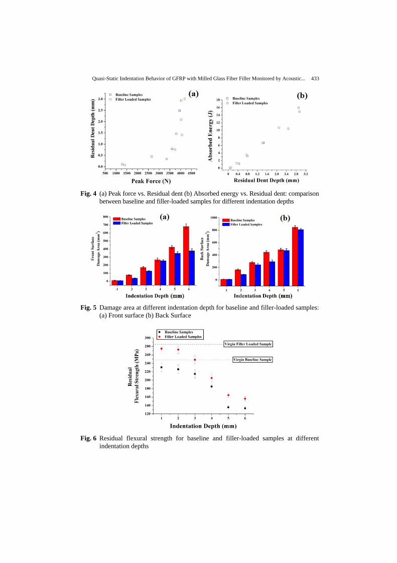
Acoustic Emission monitoring is widely employed for inspecting and identifying the sequence and the respective extent of damage mechanisms generated in fiber reinforced composites [37-39]. The microscopic failure events are detected during the tests by AE sensors as AE signals and the frequency analysis is employed to discriminate the failure modes in composite materials. Each AE signal acquired during the tests belongs, therefore, to specific damage modes with a certain amount of strain energy released. The damage mechanisms such as matrix crack, debonding, delamination and fiber breakage were discriminated, based on the peak frequency – cumulative counts vs. time plot. The frequency analysis was performed on the glass/epoxy laminates subjected to quasi-static indentation and flexural after indentation tests.
The load-displacement behavior of the glass/epoxy samples subjected to quasi-static indentation test with acoustic emission monitoring will be discussed in detail, as follows. In general, the AE events initiate after the occurrence of local plastic deformation in the samples. Figures 7 and 8 show Peak frequency & Cumulative Counts vs. time plot of corresponding load-displacement behavior for each indentation depth. The curve profile of the AE cumulative counts – time plot signifies the evolution of damage initiation and progression during loading, as previously discussed, e.g. in [24]. It was observed that the profile of the AE cumulative counts curve changes significantly with subsequent damage as loading progresses. Initially, the damage starts with lower count rates, so that the AE cumulative counts curve is almost flat while the AE signals can be mostly attributed to matrix cracking. Further loading intensifies the progression of matrix cracking within the ply at faster rates, promoting fiber/matrix debonding and fiber breakage, as will be shown in Figs. 10 and 11. Damage accumulation was indicated by a sudden and abrupt increase in the cumulative counts with a change in the slope associated with a major failure such as delamination. Finally, a sharp increase in the cumulative counts with a steep slope corresponds to unstable crack growth, resulting in the ultimate failure of the laminates. Also, the AE signals associated with different failure mechanisms were identified sequentially during the damage evolution from the peak frequency vs. time plots. It is suggested from previous literature that the peak frequency ranges in the GFRP correspond to different damage mechanisms: with some accuracy, these can be defined as 70-120 kHz for matrix cracking, 120-190 kHz for delamination, 190-260 kHz for debonding and 260-320 kHz for fiber failure.
In particular, Figs. 7 (a) and (b) show the results for a lower indentation depth of 1 mm. Both in the baseline and the filler-loaded laminates, the damage initiates in the form of matrix cracking, while fiber/matrix debonding was observed only in the case of the filler-loaded samples; delamination was not yet evident at this indentation depth. This can suggest that the filler-loaded laminates may provide higher energy dissipation through an additional toughening mechanism such as filler/matrix debonding offered by the presence of milled glass fibers. In practical terms, at 1 mm indentation depth, no significant damage was visible in both the baseline and the filler-loaded samples, except minor local indentation at the contact of the indenter. This will be confirmed in Fig. 9, with no delamination/debonding visible for 1 mm indentation depth in the baseline samples.
Figures 7(c) and (d) show the results for an indentation depth of 2 mm, where the damage onset load (or) delamination threshold load was indicated from the incipient point during quasi-static indentation. Typically, the incipient point defines the initial change in the slope or a drop in the load where delamination occurs during testing. The baseline samples

Quasi-Static Indentation Behavior of GFRP with Milled Glass Fiber Filler Monitored by Acoustic... 435
show a change in the slope during 2050N and 1.3mm indentation depth, while the filler-loaded samples indicate a change in the slope only during 2550N and 1.6mm indentation depth. Correspondingly to this load/indentation, damage accumulation was observed attributed to a sudden and abrupt increase in the AE cumulative counts with a change in the slope associated with a major failure, such as debonding/delamination, as observable from the peak frequency-time plot. These failure modes were nominal at 2 mm indentation depth and consequently exhibit a smaller damage area, as seen in Fig. 9. The size of the damaged area, the intensity of damage and relevant damage mechanism were observed to increase with indentation depth.
Fig. 7 Peak frequency & Cumulative Counts vs. Time plot of corresponding load-
displacement behavior for indentation depth. Baseline samples: (a) 1mm (c) 2mm
(e) 3mm & Filler-loaded samples: (b) 1mm (d) 2mm (f) 3mm

436 K. SARAVANAKUMAR, B.S. LAKSHMINARAYANAN, V.ARUMUGAM, et al.
The indentation response of the glass/epoxy samples subjected to 3 mm indentation
depth can be seen in Figs. 7(e) and (f). In this case, the change of the slope of the load-
displacement curve indicates reduced contact stiffness of the material due to the initiation
of damage mechanisms, such as matrix cracking, debonding and delamination, as can be
seen in Figs. 10 and 11. As previously discussed, the flat region of the curve of the AE
cumulative counts indicates the damage initiation stage attributed to low-frequency failure
mode matrix cracking, whereas the initiation of delamination in the baseline samples
occurred at 2150N and 1.3mm, followed by a sudden load drop at 2850N and 1.98mm,
corresponding to the fiber failure, as seen in Figs. 10 and 11.
In general, it is reported that the initial peak force increases consistently with indenter
displacement, accompanied by a sequence of load drops associated with significant damages
modes such as fiber failure and delamination. It can also be observed that the intensity of
delamination signals observed in the baseline samples is higher than that of the filler-loaded
samples which validates the correlation of damage area as seen in Fig. 9. In contrast, the
filler-loaded samples exhibit delamination threshold load of 2550N, corresponding to 1.7mm
indentation depth, while a sudden load drop was observed at 3280N, corresponding to
2.57mm. In practice, it was observed that the damage onset load and the fiber breakage load
exhibited by the filler-loaded samples was for 19% and 15% higher than for the baseline
samples. This result shows that damage initiation and accumulation were delayed for the
filler-loaded sample comparing to the baseline samples. In Figs. 10 and 11, it can be
observed that indentation depth of 3 mm results in compression fracture at the contact
location of the indenter causes matrix shear cracking and fiber micro-buckling while
delamination followed up by intra-laminar cracking and axial fiber splitting at the back side.
In Fig. 9, it appears that the filler-loaded samples exhibit a reduced damage area than the
baseline samples, and, moreover, the filler-loaded samples have higher contact stiffness and
load carrying capacity than the baseline samples.
Figures 8 (a) to (f) show the load-displacement behavior of the baseline and the filler-
loaded samples indented at 4, 5 and 6mm. The same trend was observed with a flat profile
of the AE cumulative counts indicating the damage initiation stage and a steep rise in the
slope of the curve showing the damage accumulation. It was observed that the damage
onset load in the baseline samples occurred at an average of 2100 N at 1.2mm followed by
a sudden load drop at 2700N and 1.8mm corresponding to the fiber failure. In contrast, the
filler-loaded samples exhibited delamination damage load and a load drop related to fiber
damage at 2500N and 1.6mm, and 3100N and 2.1mm, respectively. It is significant to
observe that the damage onset load and the fiber breakage load exhibited by the filler-
loaded samples were for about 20% and 15% higher than the baseline samples,
respectively. This is due to enhanced energy dissipation through toughening mechanism
such as filler/matrix debonding, filler interlocking/bridging which contributes to higher
load-bearing capacity.
At a higher indentation depth, a fiber failure occurs during penetration/perforation of
the samples which reduces the load resistance capability. Beyond 4 mm indentation depth,
all the samples show the same trend in peak load and absorbed energy, while no significant
increase was observed due to a more intense fiber failure. The failure occurred through
matrix shear cracking, and fiber micro-buckling at the local contact of the indenter,
followed by delamination between the adjacent plies and intra-laminar cracking (or) axial
fiber splitting through penetration/perforation of the indenter. It is clearly seen that the
Quasi-Static Indentation Behavior of GFRP with Milled Glass Fiber Filler Monitored by Acoustic... 437
delamination onset load was almost similar for all the samples while the improvement in
the fiber breakage load reduces drastically with an increasing indentation depth due to
the perforation/penetration of the samples.
Fig. 8 Peak frequency & Cumulative Counts vs. Time plot of corresponding load-
displacement behavior for indentation depth. Baseline samples: (a) 4mm (c) 5mm
(e) 6mm & Filler-loaded Samples: (b) 4mm (d) 5mm (f) 6mm
438 K. SARAVANAKUMAR, B.S. LAKSHMINARAYANAN, V.ARUMUGAM, et al.
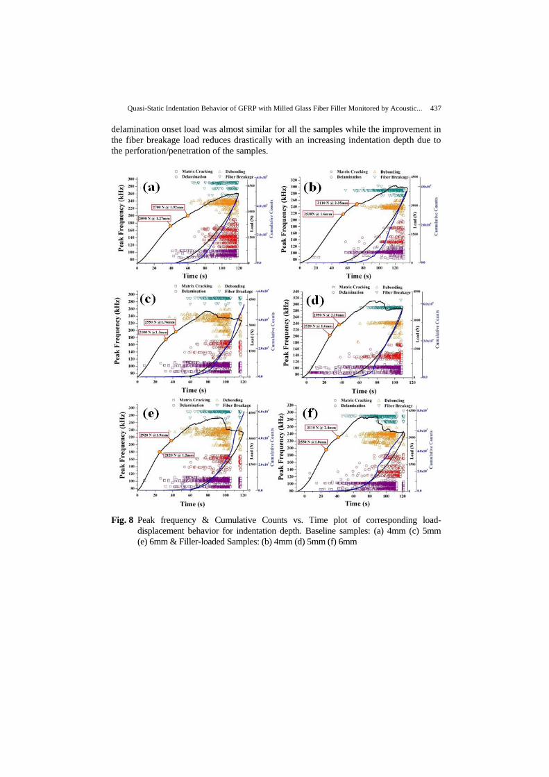
Fig. 9 Images of projected indentation damaged area at different indentation depth
Figures 10 and 11 show optical microscope images of the fractured surfaces observed
during the quasi-static indentation test in the baseline and the filler-loaded samples. At a
lower indentation depth, matrix fracture damage occurs, which decreases the localized
stiffness of the laminate, but does not result in any catastrophic failure. However, further
increasing the indentation displacement can cause the matrix cracking to progress into
delamination and fiber breakage, due to the tensile stress caused by the indenter contact. In
general, the transverse matrix cracking develops into delamination between the adjacent
plies, and finally, prevalent intra-laminar crack and in-plane fiber buckling/breakage cause
penetration and perforation damage at a higher indentation depth (4 to 6 mm). Figures 9, 10
and 11 show that the intensity of damage in the baseline samples was predominant
comparing to the filler-loaded samples, especially at a higher indentation depth.
In contrast, the damage exhibited by the filler-loaded samples was minor and delayed,
due to the improved load carrying capacity and energy absorption characteristics offered by
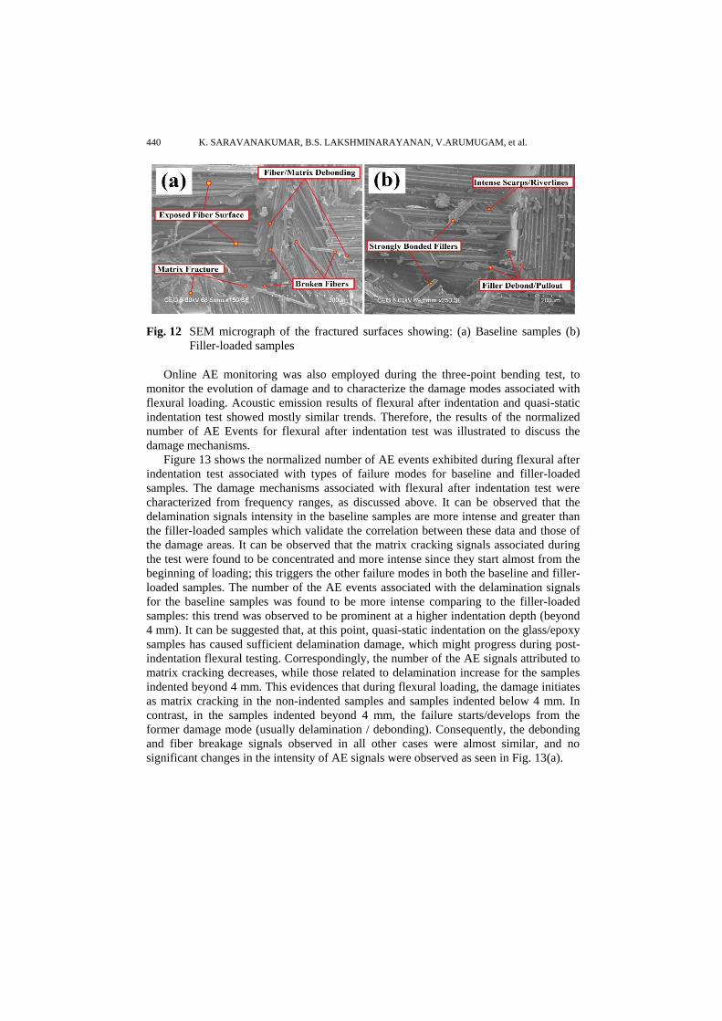
the presence of fillers. Figures 12 (a) and (b) show scanning electron microscope images of
the fractured surfaces of the baseline and the filler-loaded samples. The baseline samples

Quasi-Static Indentation Behavior of GFRP with Milled Glass Fiber Filler Monitored by Acoustic... 439
exhibit smooth and brittle fracture surface associated with no plastic deformation
corresponding to low fracture toughness of epoxy matrix. However, the fracture surface of
the filler-loaded samples indicates rough surface with intense scarps/river lines. The intense
scarps/river lines indicate hindrance of crack growth. Figure 12 (b) shows the fillers strongly
bonded to the matrix and filler debonding/pullout, which can be attributed to the additional
energy dissipation mechanisms.
Fig. 10 Optical microscopic images of the fractured surfaces observed during quasi-
static indentation test for baseline samples
Fig. 11 Optical microscopic images of the fractured surfaces observed during quasi
static indentation test for filler-loaded samples
440 K. SARAVANAKUMAR, B.S. LAKSHMINARAYANAN, V.ARUMUGAM, et al.
Fig. 12 SEM micrograph of the fractured surfaces showing: (a) Baseline samples (b)
Filler-loaded samples
Online AE monitoring was also employed during the three-point bending test, to
monitor the evolution of damage and to characterize the damage modes associated with
flexural loading. Acoustic emission results of flexural after indentation and quasi-static
indentation test showed mostly similar trends. Therefore, the results of the normalized
number of AE Events for flexural after indentation test was illustrated to discuss the
damage mechanisms.
Figure 13 shows the normalized number of AE events exhibited during flexural after
indentation test associated with types of failure modes for baseline and filler-loaded
samples. The damage mechanisms associated with flexural after indentation test were
characterized from frequency ranges, as discussed above. It can be observed that the
delamination signals intensity in the baseline samples are more intense and greater than
the filler-loaded samples which validate the correlation between these data and those of
the damage areas. It can be observed that the matrix cracking signals associated during
the test were found to be concentrated and more intense since they start almost from the
beginning of loading; this triggers the other failure modes in both the baseline and filler-
loaded samples. The number of the AE events associated with the delamination signals
for the baseline samples was found to be more intense comparing to the filler-loaded
samples: this trend was observed to be prominent at a higher indentation depth (beyond
4 mm). It can be suggested that, at this point, quasi-static indentation on the glass/epoxy
samples has caused sufficient delamination damage, which might progress during post-
indentation flexural testing. Correspondingly, the number of the AE signals attributed to
matrix cracking decreases, while those related to delamination increase for the samples
indented beyond 4 mm. This evidences that during flexural loading, the damage initiates
as matrix cracking in the non-indented samples and samples indented below 4 mm. In
contrast, in the samples indented beyond 4 mm, the failure starts/develops from the
former damage mode (usually delamination / debonding). Consequently, the debonding
and fiber breakage signals observed in all other cases were almost similar, and no
significant changes in the intensity of AE signals were observed as seen in Fig. 13(a).

Quasi-Static Indentation Behavior of GFRP with Milled Glass Fiber Filler Monitored by Acoustic... 441
Fig. 13 Types of failure modes versus normalized number of AE events for Flexural
After Indentation test: (a) Baseline Samples (b) Filler-loaded Samples
Similarly, Fig. 13 (b) shows the normalized number of the AE events with
corresponding types of failure modes exhibited by the filler-loaded samples during flexural
after indentation test. It can be observed that the normalized number of the AE events
corresponding to the matrix cracking was highly predominant for the filler-loaded samples
in all the cases (virgin and all indented samples). In contrast, the number of the AE events
corresponding to delamination signals was observed to be lower for the filler-loaded
samples than the baseline samples, even for the samples subjected to a higher indentation
depth. However, the corresponding debonding signals associated with the test in the filler-
loaded samples were greater than the baseline samples. This is due to the filler presence in
the interlaminar domain introducing toughening mechanism, such as filler debonding/
pullout resulting in more intense debonding AE events. Subsequently, the number of the
AE events related to the fiber breakage was almost similar in both the baseline and the
filler-loaded samples for all the cases of flexural after indentation.
4. CONCLUSIONS
This present work investigates the influence of milled glass fiber filler on glass/epoxy
samples subjected to quasi-static indentation and flexural after indentation tests with acoustic
emission monitoring. The evolution of damage and characterization of damage mechanisms
associated with loading were discussed, and the results were correlated with the baseline
glass/epoxy samples.
The results show that, irrespective of indentation depth, the filler-loaded samples
exhibited a slightly higher peak force for about an average of 10% than the baseline samples.
In all the cases beyond 4 mm, no significant difference in the peak load was observed,
corresponding to the predominant fiber damage during penetration/perforation of samples.
The initial contact stiffness as well as the delaminated one of the filler-loaded samples was
2181 ± 75 N/mm and 955 ± 72 N/mm, respectively, while the baseline samples showed the
initial and the delaminated contact stiffness of 1902 ± 58 N/mm and 832 ± 75 N/mm,
respectively. The filler-loaded samples showed 15% improvement in the initial and the
delaminated contact stiffness in comparison with the baseline samples.

442 K. SARAVANAKUMAR, B.S. LAKSHMINARAYANAN, V.ARUMUGAM, et al.
It was observed that the filler-loaded samples exhibited a reduced permanent depth and a
damage area by an average of 25% than the baseline samples. The presence of the filler
offers greater rigidity/stiffness and higher energy absorption through plastic deformation and
toughening mechanism, such as filler debonding/pullout, filler bridging/interlocking.
The residual flexural strength was observed to reduce gradually by an average of 15%
for an indentation depth below 3 mm with a reduction of about 30% at a higher indentation
depth in both the baseline and the filler-loaded samples, leading to a large delamination area
and intensive fiber breakage causing penetration/perforation damage. This evidences that the
beyond 3 mm, the load carrying capacity of the glass/epoxy samples decreases drastically
due to the greater accumulated damage during indentation. Besides, the filler-loaded samples
exhibited an average of 18% higher residual strength than the baseline samples.
Damage mechanisms associated with quasi-static indentation and flexural after
indentation test, as characterized from AE frequency data, were almost similar. However, in
the former the presence of delamination and debonding was more evident for the highest
indentation depths than in the latter samples.
REFERENCES
1. Atas, C., Icten, B.M., Küçük, M., 2013, Thickness effect on repeated impact response of woven fabric
composite plates, Compos Part B, 49, pp. 80–85.
2. Aktas, M., Atas, C., Icten, B.M., Karakuzu, R. 2009, An experimental investigation of the impact response of
composite laminates, Compos Struct., 87(4), pp. 307–13.
3. Fragassa, C., 2017, Marine Applications of Natural Fibre-Reinforced Composites: A Manufacturing Case
Study, In: Pellicer E, et al. (eds.), Advances in Application of Industrial Biomaterials, Springer, pp. 21-47.
4. Rohwer, K., 2016, Models for intralaminar damage and failure of fiber composites - A review, Facta
Universitatis-Series Mechanical Engineering, 14(1), pp. 1-19.
5. Fragassa, C., Pavlovic, A., Vannucchi de Camargo, F., Minak, G., 2018, Experimental evaluation of static and
dynamic properties of low styrene emission vinylester laminates reinforced by natural fibres, Polymer Testing,
69, pp. 437-449.
6. Fragassa, C., Pavlovic, A., Santulli, C., 2018, Mechanical and impact characterisation of flax and basalt fibre
bio-vinylester composites and their hybrids, Composites - Part B, 137, pp. 247-259.
7. Flores Johnson, E.A., Li, Q.M., 2011, Experimental study of the indentation of the sandwich panel with
carbon fiber reinforced polymer face sheets and polymeric foam core, Compos Part B, 42, pp. 1212-1219.
8. Xiao, J.R., Gama, B.A., Gillespie, J.W., 2007, Progressive damage and delamination in plain weave S-2 glass
/SC-15 composites under quasi-static punch-shear loading, Compos Struct., 78, pp. 182-196.
9. Abdallah, A., Bouver, C., 2009, Experimental analysis of damage creation and permanent indentation on
highly oriented plates, Compos Sci & Technol, 69, pp. 1238-1245.
10. Kaczmarek, H., Maison, S., 1994, Comparative ultrasonic analysis of damage in CFRP under static
indentation and low-velocity impact, Compos Sci & Technol, 51, pp. 11-26.
11. Lee, S.M., Zahuta, P., 1991, Instrumented impact and static Indentation of composites, J. Compos Mater, 25,
pp. 204-222.
12. He, W., Guan, Z., Li, X., Liu, D., 2013, Prediction of permanent indentation due to impact on laminated
composites based on an elastoplastic model incorporating fiber failure, Compos Struct, 96, pp. 232-242.
13. Hachemane, B., Zitoune, R., Bezzazi, B., Bouvet, C., 2013, Sandwich composites impact and indentation
behavior study, Compos Part B, 51, pp. 1-10.
14. Arabzadeh, H., Zeinoddini, M., 2013, A closed-form solution for lateral indentation of pressurized pipes
resting on a flexible bed, International Journal of Mechanical Sciences, 75, pp. 189–199.
15. Sutherland, L.S., Guedes Soares, C., 2005, Contact indentation of marine composites, Composite Structures
70, pp. 287–294.
16. Potti, S.V., Sun, C.T., 1997, Prediction of impact-induced penetration and delamination in thick composite
laminates, Int J Imp Eng, 19(1), pp. 31–48.
Quasi-Static Indentation Behavior of GFRP with Milled Glass Fiber Filler Monitored by Acoustic... 443
17. O’Masta, M.R., Crayton, D.H., Deshpande, V.S., Wadley, H.N.G., 2015, Mechanisms of penetration in
polyethylene reinforced cross-ply laminates, International Journal of Impact Engineering, 86, pp. 249-264.
18. Suresh Kumar, C., Arumugam, V., Santulli, C., 2017, Characterization of indentation damage resistance of
hybrid composite laminates using acoustic emission monitoring, Composites Part B, 111, pp. 165-178.
19. Singh, R.P., Zhang, M., Chan, D., 2002, Toughening of a brittle thermosetting polymer, pp. effects of
reinforcement particle size and volume fraction, J Mater Sci, 37, pp. 781–8.
20. Wicks, S.S., de Villoria, R.G., Wardle, B.L., 2010, Inter-laminar and intralaminar reinforcement of composite
laminates with aligned carbon nanotubes, Compos Sci Technol., 70, pp. 20–28.
21. Davis, D., Whelan, B., 2011, An experimental study of inter-laminar shear fracture toughness of a nanotube-
reinforced composite, Compos Part B, 42, pp. 105–116.
22. Adams, R.D., Cawley, P., 1988, A review of defect types and non-destructive testing techniques for composites
and bonded joints, NDT & E Inter, 21(4), pp. 201-222.
23. Fotouhi, M., Ahmadi, M., Oskouei, A.R., 2014, Acoustic emission-based study to characterize the initiation of
delamination in composite materials, J Thermoplastic Compos Mater 2014, 1-9, DOI: 10.1177/
0892705713519811.
24. Fotouhi, M., Pashmforoush, F., Ahmadi, M., 2011, Monitoring the initiation and growth of delamination in
composite materials using acoustic emission under quasi-static three- point bending test, J Reinf Plast
Compos., 30(17), pp. 1481-1493.
25. Grosse, C.U., Linzer, L.M., 2008, Signal-based AE analysis, Acoustic Emission Testing, Springer, pp. 53-99.
26. Bar, H.N., Bhat, M.R., Murthy, C.R.L., 2005, Parametric analysis of acoustic emission signals for evaluating
damage in composites using PVDF film sensors, Journal of Nondestructive Evaluation, 24(4), pp. 121–134.
27. Bussiba, M., Kupiec, S., Ifergane, R., Piat, T., 2008, Damage evolution and fracture events sequence in
various composites by acoustic emission technique, Compos. Sci. Technol. 68, pp. 1144–1155.
28. Ramirez-Jimenez, C.R., Papadakis, N., Reynolds, N., Gan, T.H., Purnell, P., Pharaoh, M., 2004, Identification
of failure modes in glass/polypropylene composites by means of the primary frequency content of the acoustic
emission event, Compos Sci Technol, 64, pp. 1819–27.
29. Asokan, R., Arumugam, V., Santulli, C., Barath Kumar, S., Stanley A.J., 2011, Investigation of the strength of
the failure modes in GFRP laminates using acoustic emission monitoring, Int J Poly Technol, 3(2), pp. 57–65.
30. ASTM D 6264/D6264 M-2017, Test method for measuring the damage resistance of a fiber-reinforced
polymer-matrix composite to a concentrated quasi-static indentation force.
31. Arumugam, V., Sajith, S., Stanley, A.J., 2011, Acoustic Emission Characterization of Failure Modes in GFRP
Laminates Under Mode I Delamination, J Nondestructive Eval, 30(3), pp 213–219.
32. Hafeez, F., Almaskari, F., 2015, Experimental investigation of the scaling laws in laterally indented filament
wound tubes supported with V-shaped cradles, Composite Structures, 126, pp. 265–284.
33. Gama, B.A., Islam, S.M.W., Rahman, M., Gillespie, J.W., et al., 2005, Punch shear behavior of thick-section
composites under quasi-static, low velocity, and ballistic impact loading. SAMPE J, 41(4), pp. 6–13.
34. Jefferson, A.J, Arumugam, V., Saravanakumar, K., Dhakal, H.N., Santulli, C., 2015, Compression after impact
strength of repaired GFRP composite laminates under repeated impact loading, Compos Struct, 133,
pp. 911–20.
35. Mitrevski, T., Marshall, I.H., Thomson, R., Jones, R., Whittingham, B., 2005, The effect of impactor shape on
the impact response of composite laminates. Compos Struct, 67, pp. 139-148.
36. Zhang, Z.Y., Richardson, M.O.W., 2007, Low velocity impact induced damage evaluation and its effect on the
residual flexural properties of pultruded GRP composites, Compos Struct, 81, pp. 195-201.
37. Heidary H., Ahmadi M., Rahimi A, Minak G,, 2013, Wavelet-based acoustic emission characterization of
residual strength of drilled composite materials, J Compos Mater 47, pp. 2897-2908.
38. Petrucci, R., Santulli, C., Puglia, D., Nisini, E., Sarasini, F., Tirillò, J., Torre, L., Minak, G., Kenny, J.M., 2015,
Impact and post-impact damage characterisation of hybrid composite laminates based on basalt fibres in
combination with flax, hemp and glass fibres manufactured by vacuum infusion, Compos Part B, 69, pp.
507-515.
39. Mohammadi, R., Najafabadi, M.A., Saeedifar, M., Yousefi, J., Minak, G., 2017, Correlation of acoustic
emission with finite element predicted damages in open-hole tensile laminated composites, Compos Part B,
108, pp. 427-435.