Quarter-Turn Ball Valve Systems Type 265X Manual ... · • Ultrapure water • Slightly aggressive...
16
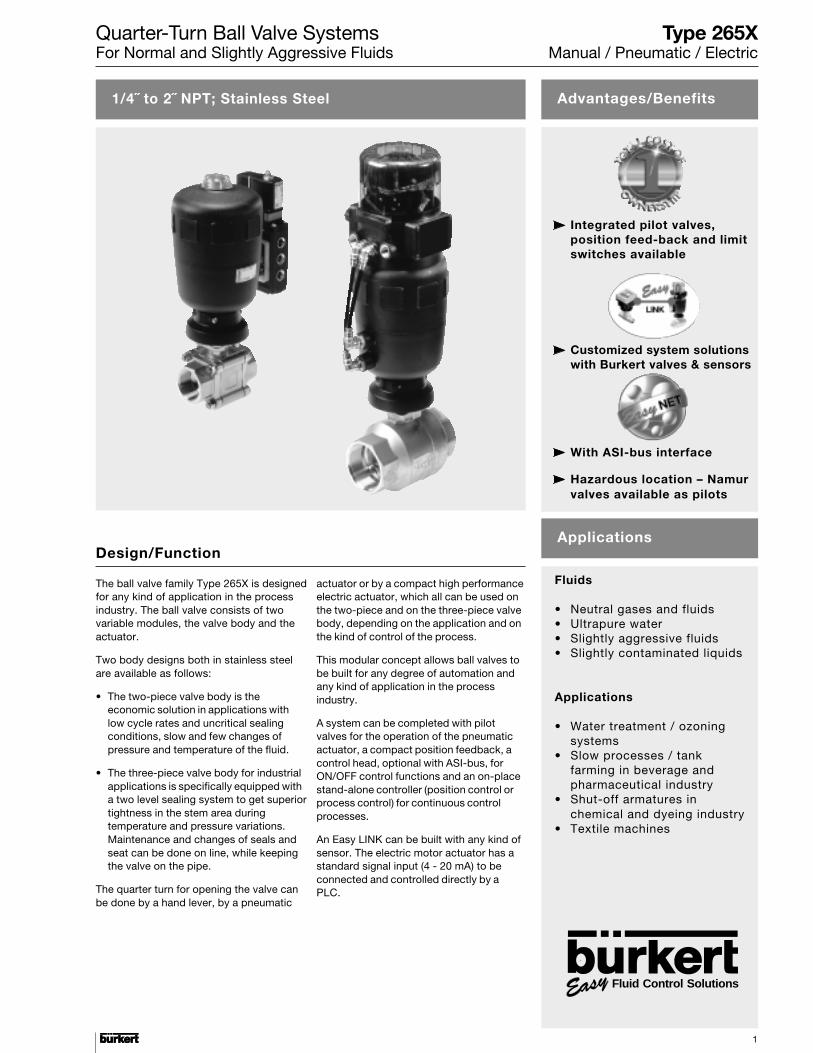
Quarter-Turn Ball Valve Systems For Normal and Slightly Aggressive Fluids 1 1/4˝ to 2˝ NPT; Stainless Steel Advantages/Benefits Applications The ball valve family Type 265X is designed for any kind of application in the process industry. The ball valve consists of two variable modules, the valve body and the actuator. Two body designs both in stainless steel are available as follows: • The two-piece valve body is the economic solution in applications with low cycle rates and uncritical sealing conditions, slow and few changes of pressure and temperature of the fluid. • The three-piece valve body for industrial applications is specifically equipped with a two level sealing system to get superior tightness in the stem area during temperature and pressure variations. Maintenance and changes of seals and seat can be done on line, while keeping the valve on the pipe. The quarter turn for opening the valve can be done by a hand lever, by a pneumatic Integrated pilot valves, position feed-back and limit switches available Customized system solutions with Burkert valves & sensors With ASI-bus interface Hazardous location – Namur valves available as pilots Fluids • Neutral gases and fluids • Ultrapure water • Slightly aggressive fluids • Slightly contaminated liquids Applications • Water treatment / ozoning systems • Slow processes / tank farming in beverage and pharmaceutical industry • Shut-off armatures in chemical and dyeing industry • Textile machines Design/Function actuator or by a compact high performance electric actuator, which all can be used on the two-piece and on the three-piece valve body, depending on the application and on the kind of control of the process. This modular concept allows ball valves to be built for any degree of automation and any kind of application in the process industry. A system can be completed with pilot valves for the operation of the pneumatic actuator, a compact position feedback, a control head, optional with ASI-bus, for ON/OFF control functions and an on-place stand-alone controller (position control or process control) for continuous control processes. An Easy LINK can be built with any kind of sensor. The electric motor actuator has a standard signal input (4 - 20 mA) to be connected and controlled directly by a PLC. Type 265X Manual / Pneumatic / Electric Fluid Control Solutions
Transcript of Quarter-Turn Ball Valve Systems Type 265X Manual ... · • Ultrapure water • Slightly aggressive...
Quarter-Turn Ball Valve SystemsFor Normal and Slightly Aggressive Fluids
1
1/4˝ to 2˝ NPT; Stainless Steel Advantages/Benefits
Applications
The ball valve family Type 265X is designedfor any kind of application in the processindustry. The ball valve consists of twovariable modules, the valve body and theactuator.
Two body designs both in stainless steelare available as follows:
• The two-piece valve body is theeconomic solution in applications withlow cycle rates and uncritical sealingconditions, slow and few changes ofpressure and temperature of the fluid.
• The three-piece valve body for industrialapplications is specifically equipped witha two level sealing system to get superiortightness in the stem area duringtemperature and pressure variations.Maintenance and changes of seals andseat can be done on line, while keepingthe valve on the pipe.
The quarter turn for opening the valve canbe done by a hand lever, by a pneumatic
Integrated pilot valves,position feed-back and limitswitches available
Customized system solutionswith Burkert valves & sensors
With ASI-bus interface
Hazardous location – Namurvalves available as pilots
Fluids
• Neutral gases and fluids• Ultrapure water• Slightly aggressive fluids• Slightly contaminated liquids
Applications
• Water treatment / ozoningsystems
• Slow processes / tankfarming in beverage andpharmaceutical industry
• Shut-off armatures inchemical and dyeing industry
• Textile machines
Design/Function
actuator or by a compact high performanceelectric actuator, which all can be used onthe two-piece and on the three-piece valvebody, depending on the application and onthe kind of control of the process.
This modular concept allows ball valves tobe built for any degree of automation andany kind of application in the processindustry.
A system can be completed with pilotvalves for the operation of the pneumaticactuator, a compact position feedback, acontrol head, optional with ASI-bus, forON/OFF control functions and an on-placestand-alone controller (position control orprocess control) for continuous controlprocesses.
An Easy LINK can be built with any kind ofsensor. The electric motor actuator has astandard signal input (4 - 20 mA) to beconnected and controlled directly by aPLC.
Type 265XManual / Pneumatic / Electric
Fluid Control Solutions
JLL
IAC SL
Quarter-Turn Ball Valve SystemsFor Normal and Slightly Aggressive Fluids
22
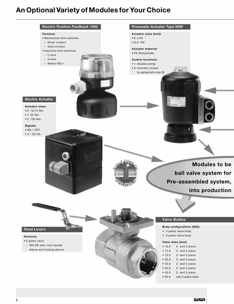
An Optional Variety of Modules for Your Choice
Pneumatic Actuator Type 2050
Actuator sizes [mm]:
• E: ø 63
• G:ø 100
Actuator material:
• PA (Polyamide)
Control functions:
• I: double acting
• A: normally closed
by spring (only size G)
Valve Bodies
Body configurations (ISO):
• 2-piece valve body
• 3-piece valve body
Valve sizes [mm]:
• 10.0 2- and 3 piece
• 12.0 2- and 3 piece
• 15.0 2- and 3 piece
• 20.0 2- and 3 piece
• 25.0 2- and 3 piece
• 32.0 2- and 3 piece
• 40.0 2- and 3 piece
• 50.0 only 2-piece valve
Hand Levers
Versions:
• 2-piece valve
– 304 SS with vinyl handle
sleeve and locking device
Modules to be
ball valve system for
Pre-assembled system,
into production
Electric Actuator
Actuator sizes:
• 0: 10/12 Nm
• 1: 25 Nm
• 2: 100 Nm
Signals:
• ON / OFF
• 4 - 20 mA
Electric Position Feedback 1062
Versions:
• Mechanical limit switches
– Silver contact
– Gold contact
• Inductive limit switches
– 2-wire
– 3-wire
– Namur EEx-i
Quarter-Turn Ball Valve SystemsFor Normal and Slightly Aggressive Fluids
3
to select
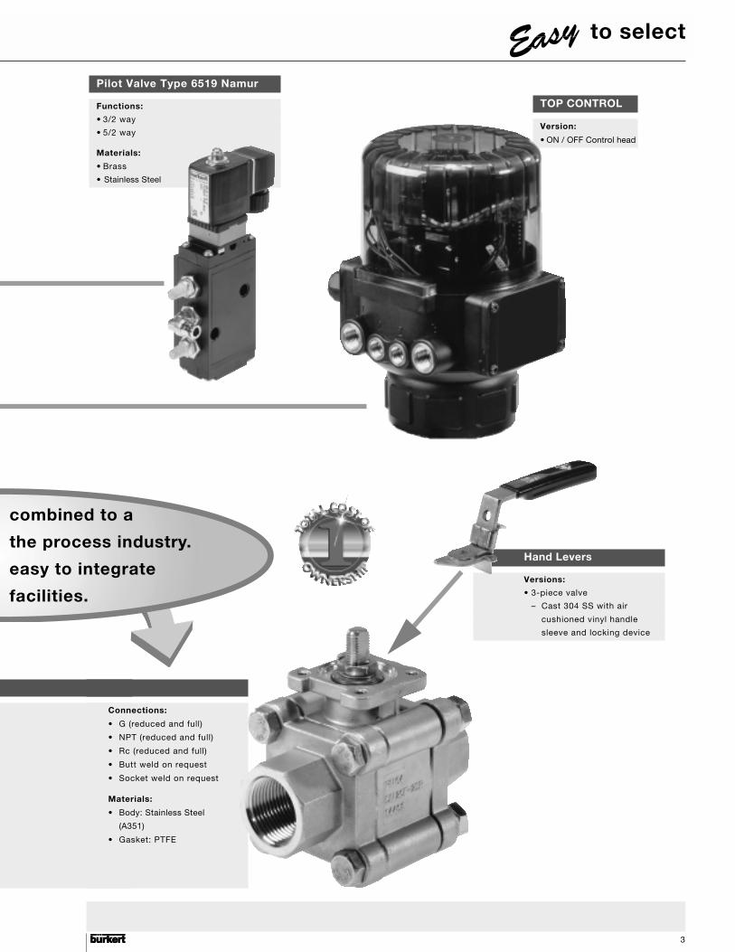
Pilot Valve Type 6519 Namur
Functions:
• 3/2 way
• 5/2 way
Materials:
• Brass
• Stainless Steel
Connections:
• G (reduced and full)
• NPT (reduced and full)
• Rc (reduced and full)
• Butt weld on request
• Socket weld on request
Materials:
• Body: Stainless Steel
(A351)
• Gasket: PTFE
Hand Levers
Versions:
• 3-piece valve
– Cast 304 SS with air
cushioned vinyl handle
sleeve and locking device
combined to a
the process industry.
easy to integrate
facilities.
TOP CONTROL
Version:
• ON / OFF Control head
Quarter-Turn Ball Valve SystemsFor Normal and Slightly Aggressive Fluids
44
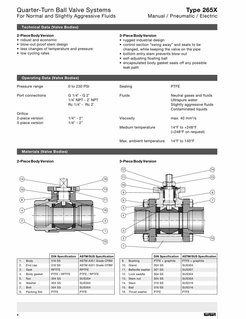
Technical Data (Valve Bodies)
2-Piece Body Version• robust and economic• blow-out proof stem design• less changes of temperature and pressure• low cycling rates
3-Piece Body Version• rugged industrial design• control section “swing away” and seats to be
changed, while keeping the valve on the pipe• bottom entry stem prevents blow-out• self-adjusting floating ball• encapsulated body gasket seals off any possible
leak path
Operating Data (Valve Bodies)
Materials (Valve Bodies)
Pressure range 0 to 230 PSI
Port connections G 1/4˝ - G 2˝1/4˝ NPT - 2˝ NPTRc 1/4˝ - Rc 2˝
Orifice2-piece version 1/4" - 2"3-piece version 1/4" - 2"
Sealing PTFE
Fluids Neutral gases and fluidsUltrapure waterSlightly aggressive fluidsContaminated liquids
Viscosity max. 40 mm2/s
Medium temperature 14°F to +248°F(>248°F on request)
Max. ambient temperature 14°F to 140°F
12
11
10
9
6
5
4
3
2
1
15
7
8
13
14
14
10
8
4
2
15
1
3
16
11
13
16
2-Piece Body Version 3-Piece Body Version
DIN Specification ASTM/SUS Specification
1. Body 316 SS ASTM A351 Grade CF8M
2. End cap 316 SS ASTM A351 Grade CF8M
3. Seat RPTFE RPTFE
4. Body gasket PTFE / RPTFE PTFE / RPTFE
5. Nut 304 SS SUS304
6. Washer 304 SS SUS304
7. Bolt 304 SS SUS304
8. Packing Set PTFE PTFE
DIN Specification ASTM/SUS Specification
9. Bushing PTFE + graphite PTFE + graphite
10. Gland 304 SS SUS304
11. Belleville washer 301 SS SUS301
12. Lock saddle 304 SS SUS304
13. Stem nut 304 SS SUS304
14. Stem 316 SS SUS316
15. Ball 316 SS SUS316
16. Thrust washer PTFE PTFE
Type 265XManual / Pneumatic / Electric
Quarter-Turn Ball Valve SystemsFor Normal and Slightly Aggressive Fluids
5
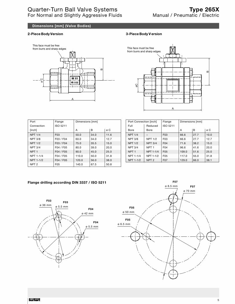
Port Flange Dimensions [mm]
Connection ISO 5211
[inch] A B ø C
NPT 1/4 F03 50.0 34.0 11.6
NPT 3/8 F03 / F04 60.0 34.0 12.7
NPT 1/2 F03 / F04 75.0 35.5 15.0
NPT 3/4 F04 / F05 80.0 39.0 20.0
NPT 1 F04 / F05 90.0 45.0 25.0
NPT 1-1/4 F04 / F05 110.0 50.0 31.8
NPT 1-1/2 F04 / F05 120.0 56.0 38.0
NPT 2 F05 140.0 67.5 50.8
Port Connection [inch] Flange Dimensions [mm]
Full Reduced ISO 5211
Bore Bore A B ø C
NPT 1/4 – F03 66.6 27.7 10.0
NPT 3/8 NPT 1/2 F03 66.6 27.7 12.7
NPT 1/2 NPT 3/4 F04 71.6 38.2 15.0
NPT 3/4 NPT 1 F04 96.6 41.6 20.0
NPT 1 NPT 1-1/4 F05 109.0 51.6 25.0
NPT 1-1/4 NPT 1-1/2 F05 117.0 55.0 31.8
NPT 1-1/2 NPT 2 F07 129.0 66.0 38.1
Dimensions [mm] (Valve Bodies)
2-Piece Body Version 3-Piece Body V ersion
ø C
AB
This face must be freefrom burrs and sharp edges This face must be free
from burrs and sharp edges
øC
B
A
F07
ø 8.5 mm F07
ø 70 mm
F05
ø 6.5 mm
F05
ø 50 mm
F04
ø 5.5 mm
F04
ø 42 mm
F03
ø 5.5 mm
F03
ø 36 mm
Flange drilling according DIN 3337 / ISO 5211
Type 265XManual / Pneumatic / Electric
Quarter-Turn Ball Valve SystemsFor Normal and Slightly Aggressive Fluids
66
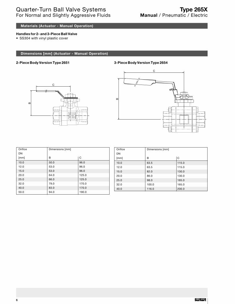
Materials (Actuator - Manual Operation)
Dimensions [mm] (Actuator - Manual Operation)
2-Piece Body Version Type 2651 3-Piece Body Version Type 2654
Handles for 2- and 3-Piece Ball Valve• SS304 with vinyl plastic cover
C
B
C
B
Orifice Dimensions [mm]
DN
[mm] B C
10.0 63.5 115.0
12.0 63.5 115.0
15.0 82.0 130.0
20.0 86.0 130.0
25.0 98.0 165.0
32.0 100.0 165.0
40.0 116.0 200.0
Orifice Dimensions [mm]
DN
[mm] B C
10.0 50.0 96.0
12.0 53.0 96.0
15.0 53.0 96.0
20.0 64.0 125.0
25.0 66.0 125.0
32.0 79.0 170.0
40.0 83.0 170.0
50.0 94.0 190.0
Type 265XManual / Pneumatic / Electric
Quarter-Turn Ball Valve SystemsFor Normal and Slightly Aggressive Fluids
7
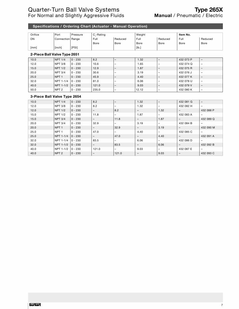
Specifications / Ordering Chart (Actuator - Manual Operation)
Orifice Port Pressure Cv-Rating Weight Item No.
DN Connection Range Full Reduced Full Reduced Full Reduced
Bore Bore Bore Bore Bore Bore
[mm] [inch] [PSI] [lb.]
10.0 NPT 1/4 0 - 230 8.2 – 1.32 – 432 073 P –
12.0 NPT 3/8 0 - 230 10.6 – 1.65 – 432 074 Q –
15.0 NPT 1/2 0 - 230 12.9 – 1.87 – 432 075 R –
20.0 NPT 3/4 0 - 230 30.6 – 3.19 – 432 076 J –
25.0 NPT 1 0 - 230 45.9 – 4.40 – 432 077 K –
32.0 NPT 1-1/4 0 - 230 81.0 – 6.06 – 432 078 U –
40.0 NPT 1-1/2 0 - 230 121.0 – 9.03 – 432 079 V –
50.0 NPT 2 0 - 230 235.0 – 12.12 – 432 080 K –
10.0 NPT 1/4 0 - 230 8.2 – 1.32 – 432 081 G –
12.0 NPT 3/8 0 - 230 8.2 – 1.32 – 432 082 H –
12.0 NPT 1/2 0 - 230 – 8.2 – 1.32 – 432 088 P
15.0 NPT 1/2 0 - 230 11.8 – 1.87 – 432 083 A –
15.0 NPT 3/4 0 - 230 – 11.8 – 1.87 – 432 089 Q
20.0 NPT 3/4 0 - 230 32.9 – 3.19 – 432 084 B –
20.0 NPT 1 0 - 230 – 32.9 – 3.19 – 432 090 M
25.0 NPT 1 0 - 230 47.0 – 4.40 – 432 085 C –
25.0 NPT 1-1/4 0 - 230 – 47.0 – 4.40 – 432 091 A
32.0 NPT 1-1/4 0 - 230 83.5 – 6.06 – 432 086 D –
32.0 NPT 1-1/2 0 - 230 – 83.5 – 6.06 – 432 092 B
40.0 NPT 1-1/2 0 - 230 121.0 – 9.03 – 432 087 E –
40.0 NPT 2 0 - 230 – 121.0 – 9.03 – 432 093 C
2-Piece Ball Valve Type 2651
3-Piece Ball Valve Type 2654
Type 265XManual / Pneumatic / Electric
Quarter-Turn Ball Valve SystemsFor Normal and Slightly Aggressive Fluids
88
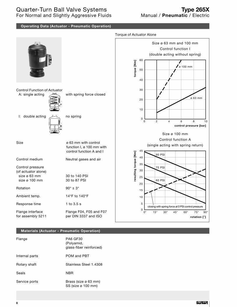
Operating Data (Actuator - Pneumatic Operation)
Materials (Actuator - Pneumatic Operation)
Flange PA6 GF30(Polyamid,glass-fiber reinforced)
Internal parts POM and PBT
Rotary shaft Stainless Steel 1.4308
Seals NBR
Service ports Brass (size ø 63 mm)SS (size ø 100 mm)
Size ø 100 mm
Control function A
(single acting with spring return)
Size ø 63 mm and 100 mm
Control function I
(double acting without spring)
control pressure [bar]
0 2 4 6 8 100
10
20
30
40
50
60
ø 100 mm
ø 63 mm
torq
ue
[N
m]
rotation [°]
0° 15° 30° 45° 60° 75°0
5
10
15
20
25
30
90 PSI
resu
ltin
g t
orq
ue
[N
m]
90°
35
40
45
closing with spring force at 0 PSI control pressure
75 PSI
60 PSI
Control Function of ActuatorA: single acting with spring force closed
I: double acting no spring
Size ø 63 mm with controlfunction I, ø 100 mm withcontrol function A and I
Control medium Neutral gases and air
Control pressure(of actuator alone)
size ø 63 mm 30 to 140 PSIsize ø 100 mm 30 to 87 PSI
Rotation 90° ± 3°
Ambient temp. 14°F to 140°F
Response time 1 to 3.5 s
Flange interface Flange F04, F05 and F07for assembly 5211 per DIN 3337 and ISO
Type 265XManual / Pneumatic / Electric
Torque of Actuator Alone
Quarter-Turn Ball Valve SystemsFor Normal and Slightly Aggressive Fluids
9
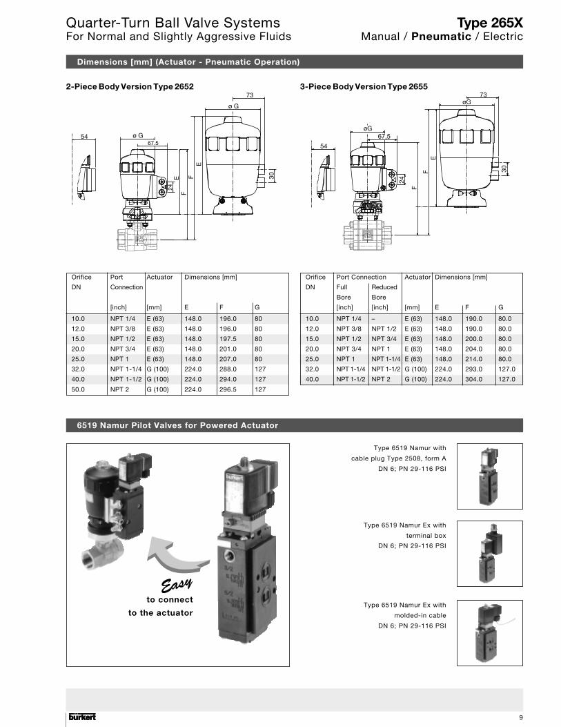
Orifice Port Actuator Dimensions [mm]
DN Connection
[inch] [mm] E F G
10.0 NPT 1/4 E (63) 148.0 196.0 80
12.0 NPT 3/8 E (63) 148.0 196.0 80
15.0 NPT 1/2 E (63) 148.0 197.5 80
20.0 NPT 3/4 E (63) 148.0 201.0 80
25.0 NPT 1 E (63) 148.0 207.0 80
32.0 NPT 1-1/4 G (100) 224.0 288.0 127
40.0 NPT 1-1/2 G (100) 224.0 294.0 127
50.0 NPT 2 G (100) 224.0 296.5 127
Dimensions [mm] (Actuator - Pneumatic Operation)
2-Piece Body Version Type 2652 3-Piece Body Version Type 2655
54 ø G67.5
73
ø G
30
EF
FE
24
Orifice Port Connection Actuator Dimensions [mm]
DN Full Reduced
Bore Bore
[inch] [inch] [mm] E F G
10.0 NPT 1/4 – E (63) 148.0 190.0 80.0
12.0 NPT 3/8 NPT 1/2 E (63) 148.0 190.0 80.0
15.0 NPT 1/2 NPT 3/4 E (63) 148.0 200.0 80.0
20.0 NPT 3/4 NPT 1 E (63) 148.0 204.0 80.0
25.0 NPT 1 NPT 1-1/4 E (63) 148.0 214.0 80.0
32.0 NPT 1-1/4 NPT 1-1/2 G (100) 224.0 293.0 127.0
40.0 NPT 1-1/2 NPT 2 G (100) 224.0 304.0 127.0
6519 Namur Pilot Valves for Powered Actuator
Type 6519 Namur with
cable plug Type 2508, form A
DN 6; PN 29-116 PSI
Type 6519 Namur Ex with
terminal box
DN 6; PN 29-116 PSI
Type 6519 Namur Ex with
molded-in cable
DN 6; PN 29-116 PSI
to connect
to the actuator
54
øG67,5
24
F
FE
øG73
30
Type 265XManual / Pneumatic / Electric
Quarter-Turn Ball Valve SystemsFor Normal and Slightly Aggressive Fluids
1010
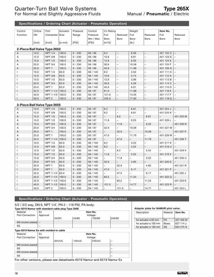
Control Orifice Port Actuator Pressure Control Cv-Rating Weight Item No.
Function DN Connection Size Range Pressure Full Reduced Full Reduced Full Reduced
Min / Max Bore Bore Bore Bore Bore Bore
[mm] [inch] [ø mm] [PSI] [PSI] [m3/h] [lb.]
2-Piece Ball Valve Type 2652A 10.0 NPT 1/4 100.0 0 - 230 58 / 89 8.2 – 8.59 – 431 122 C –
A 12.0 NPT 3/8 100.0 0 - 230 58 / 89 10.6 – 8.81 – 431 123 D –
A 15.0 NPT 1/2 100.0 0 - 230 58 / 89 12.9 – 9.03 – 431 124 E –
A 20.0 NPT 3/4 100.0 0 - 230 58 / 89 30.6 – 10.58 – 431 125 F –
A 25.0 NPT 1 100.0 0 - 230 58 / 89 45.9 – 11.68 – 431 126 G –
I 10.0 NPT 1/4 63.0 0 - 230 58 / 140 8.2 – 3.52 – 431 111 H –
I 12.0 NPT 3/8 63.0 0 - 230 58 / 140 10.6 – 3.74 – 431 112 A –
I 15.0 NPT 1/2 63.0 0 - 230 58 / 140 12.9 – 3.96 – 431 113 B –
I 20.0 NPT 3/4 63.0 0 - 230 58 / 140 30.6 – 5.29 – 431 114 C –
I 25.0 NPT 1 63.0 0 - 230 58 / 140 45.9 – 6.61 – 431 115 D –
I 32.0 NPT 1-1/4 100.0 0 - 230 58 / 87 81.0 – 11.68 – 431 116 E –
I 40.0 NPT 1-1/2 100.0 0 - 230 58 / 87 121.0 – 14.55 – 431 117 F –
I 50.0 NPT 2 100.0 0 - 230 58 / 87 235.0 – 17.63 – 431 118 Q –
3-Piece Ball Valve Type 2655A 10.0 NPT 1/4 100.0 0 - 230 58 / 87 8.2 – 8.81 – 431 224 J –
A 12.0 NPT 3/8 100.0 0 - 230 58 / 87 8.2 – 8.81 – 431 225 K –
A 12.0 NPT 1/2 100.0 0 - 230 58 / 87 – 8.2 – 8.81 – 431 235 M
A 15.0 NPT 1/2 100.0 0 - 230 58 / 87 11.8 – 9.25 – 431 226 L –
A 15.0 NPT 3/4 100.0 0 - 230 58 / 87 – 11.8 – 9.25 – 431 236 N
A 20.0 NPT 3/4 100.0 0 - 230 58 / 87 32.9 – 10.58 – 431 227 M –
A 20.0 NPT 1 100.0 0 - 230 58 / 87 – 32.9 – 10.58 – 431 237 P
A 25.0 NPT 1 100.0 0 - 230 58 / 87 47.0 – 11.79 – 431 228 W –
A 25.0 NPT 1-1/4 100.0 0 - 230 58 / 87 – 47.0 – 11.79 – 431 238 Y
I 10.0 NPT 1/4 63.0 0 - 230 58 / 140 8.2 – 3.52 – 431 217 K –
I 12.0 NPT 3/8 63.0 0 - 230 58 / 140 8.2 – 3.52 – 431 218 U –
I 12.0 NPT 1/2 63.0 0 - 230 58 / 140 – 8.2 – 3.52 – 431 229 X
I 15.0 NPT 1/2 63.0 0 - 230 58 / 140 11.8 – 3.52 – 431 219 V –
I 15.0 NPT 3/4 63.0 0 - 230 58 / 140 – 11.8 – 3.52 – 431 230 U
I 20.0 NPT 3/4 63.0 0 - 230 58 / 140 32.9 – 4.85 – 431 220 S –
I 20.0 NPT 1 63.0 0 - 230 58 / 140 – 32.9 – 4.85 – 431 231 R
I 25.0 NPT 1 63.0 0 - 230 58 / 140 47.0 – 6.17 – 431 221 P –
I 25.0 NPT 1-1/4 63.0 0 - 230 58 / 140 – 47.0 – 6.17 – 431 232 J
I 32.0 NPT 1-1/4 100.0 0 - 230 58 / 140 83.5 – 11.24 – 431 222 Q –
I 32.0 NPT 1-1/2 100.0 0 - 230 58 / 140 – 83.5 – 11.24 – 431 233 K
I 40.0 NPT 1-1/2 100.0 0 - 230 58 / 140 121.0 – 14.77 – 431 223 R –
I 40.0 NPT 2 100.0 0 - 230 58 / 140 – 121.0 – 14.77 – 431 234 L
Specifications / Ordering Chart (Actuator - Pneumatic Operation)
5/2 / 3/2 way, DN 6, NPT 1/4˝, PN 2 - 116 PSI, PA body:Type 6519 Namur with standard cable plug Type 2508
Material Ex Item No.Port Connection Approval Voltage
24/DC 24/60 120/60 240/60
MS (nickel-plated) –SS –
Type 6519 Namur Ex with molded-in cableMaterial Ex Item No.Port Connection Approval Voltage
024/UC 120/UC 240/UC –
MS (nickel-plated) –SS –MS (nickel-plated) –
SS –
Specifications / Ordering Chart (Actuator - Pneumatic Operation)
Adapter plate for NAMUR pilot valve:
Description Material Item No.
for actuator ø 63 mm PA 427 405 Mfor actuator ø 100 mm Brass 637 114 Jfor actuator ø 100 mm SS 634 275 G
For other versions, please see datasheets 6519 Namur and 6519 Namur Ex
Type 265XManual / Pneumatic / Electric
Quarter-Turn Ball Valve SystemsFor Normal and Slightly Aggressive Fluids
11
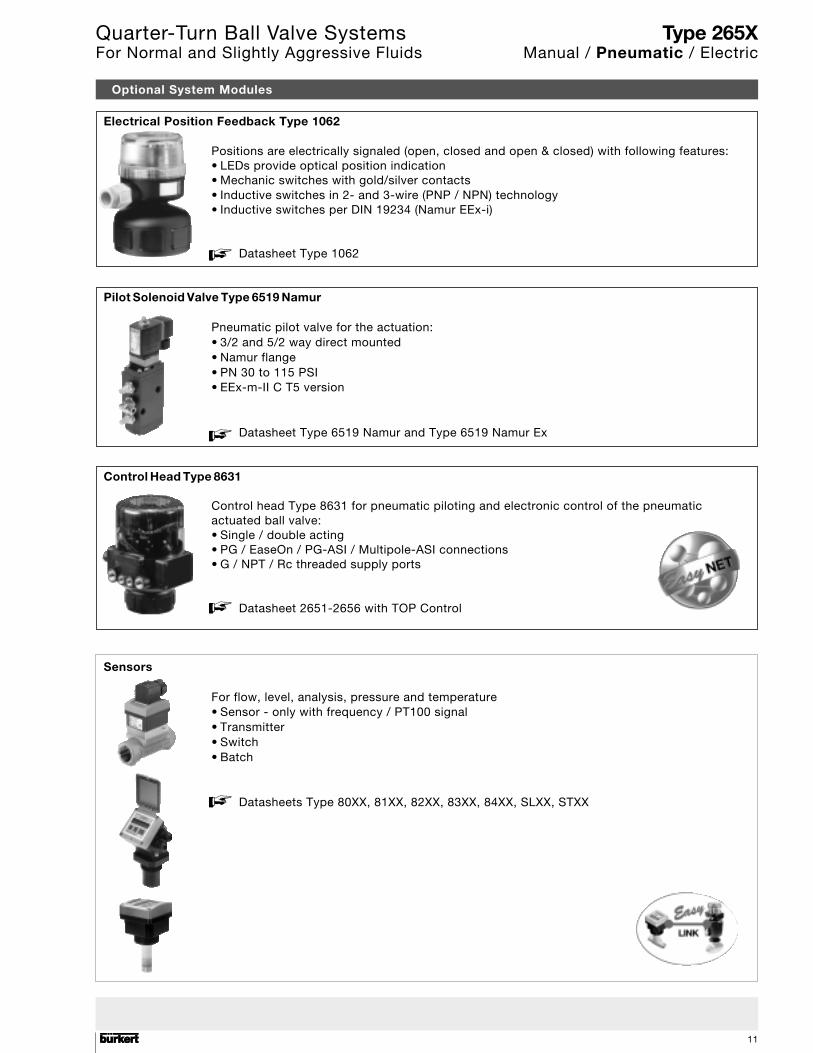
Optional System Modules
Electrical Position Feedback Type 1062
Positions are electrically signaled (open, closed and open & closed) with following features:• LEDs provide optical position indication• Mechanic switches with gold/silver contacts• Inductive switches in 2- and 3-wire (PNP / NPN) technology• Inductive switches per DIN 19234 (Namur EEx-i)
Datasheet Type 1062
Pilot Solenoid Valve Type 6519 Namur
Pneumatic pilot valve for the actuation:• 3/2 and 5/2 way direct mounted• Namur flange• PN 30 to 115 PSI• EEx-m-II C T5 version
Datasheet Type 6519 Namur and Type 6519 Namur Ex
Control Head Type 8631
Control head Type 8631 for pneumatic piloting and electronic control of the pneumaticactuated ball valve:• Single / double acting• PG / EaseOn / PG-ASI / Multipole-ASI connections• G / NPT / Rc threaded supply ports
Datasheet 2651-2656 with TOP Control
Sensors
For flow, level, analysis, pressure and temperature• Sensor - only with frequency / PT100 signal• Transmitter• Switch• Batch
Datasheets Type 80XX, 81XX, 82XX, 83XX, 84XX, SLXX, STXX
Type 265XManual / Pneumatic / Electric
Quarter-Turn Ball Valve SystemsFor Normal and Slightly Aggressive Fluids
1212
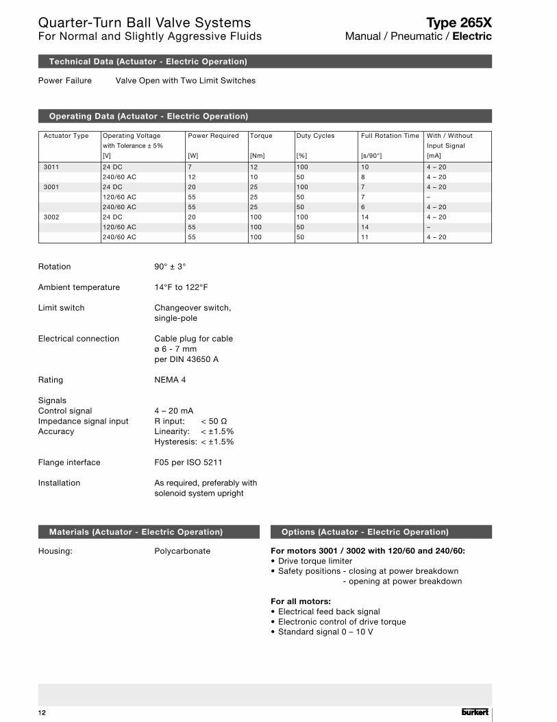
Operating Data (Actuator - Electric Operation)
Rotation 90° ± 3°
Ambient temperature 14°F to 122°F
Limit switch Changeover switch,single-pole
Electrical connection Cable plug for cableø 6 - 7 mmper DIN 43650 A
Rating NEMA 4
SignalsControl signal 4 – 20 mAImpedance signal input R input: < 50 ΩAccuracy Linearity: < ±1.5%
Hysteresis: < ±1.5%
Flange interface F05 per ISO 5211
Installation As required, preferably withsolenoid system upright
Materials (Actuator - Electric Operation)
Housing: Polycarbonate
Technical Data (Actuator - Electric Operation)
Power Failure Valve Open with Two Limit Switches
Actuator Type Operating Voltage Power Required Torque Duty Cycles Full Rotation Time With / Without
with Tolerance ± 5% Input Signal
[V] [W] [Nm] [%] [s/90°] [mA]
3011 24 DC 7 12 100 10 4 – 20
240/60 AC 12 10 50 8 4 – 20
3001 24 DC 20 25 100 7 4 – 20
120/60 AC 55 25 50 7 –
240/60 AC 55 25 50 6 4 – 20
3002 24 DC 20 100 100 14 4 – 20
120/60 AC 55 100 50 14 –
240/60 AC 55 100 50 11 4 – 20
Options (Actuator - Electric Operation)
For motors 3001 / 3002 with 120/60 and 240/60:• Drive torque limiter• Safety positions - closing at power breakdown
- opening at power breakdown
For all motors:• Electrical feed back signal• Electronic control of drive torque• Standard signal 0 – 10 V
Type 265XManual / Pneumatic / Electric
Quarter-Turn Ball Valve SystemsFor Normal and Slightly Aggressive Fluids
13
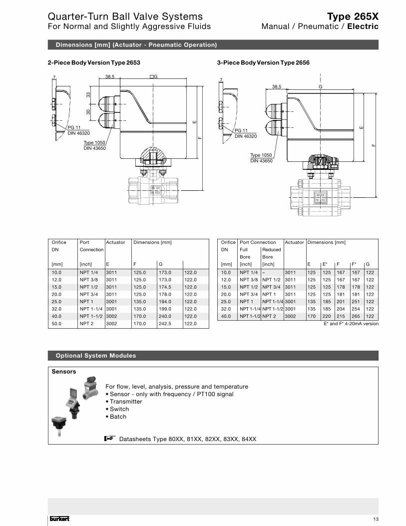
Dimensions [mm] (Actuator - Pneumatic Operation)
2-Piece Body Version Type 2653 3-Piece Body Version Type 2656
Orifice Port Actuator Dimensions [mm]
DN Connection
[mm] [inch] E F G
10.0 NPT 1/4 3011 125.0 173.0 122.0
12.0 NPT 3/8 3011 125.0 173.0 122.0
15.0 NPT 1/2 3011 125.0 174.5 122.0
20.0 NPT 3/4 3011 125.0 178.0 122.0
25.0 NPT 1 3001 135.0 194.0 122.0
32.0 NPT 1-1/4 3001 135.0 199.0 122.0
40.0 NPT 1-1/2 3002 170.0 240.0 122.0
50.0 NPT 2 3002 170.0 242.5 122.0
Orifice Port Connection Actuator Dimensions [mm]
DN Full Reduced
Bore Bore
[mm] [inch] [inch] E E* F F* G
10.0 NPT 1/4 – 3011 125 125 167 167 122
12.0 NPT 3/8 NPT 1/2 3011 125 125 167 167 122
15.0 NPT 1/2 NPT 3/4 3011 125 125 178 178 122
20.0 NPT 3/4 NPT 1 3011 125 125 181 181 122
25.0 NPT 1 NPT 1-1/4 3001 135 185 201 251 122
32.0 NPT 1-1/4 NPT 1-1/2 3001 135 185 204 254 122
40.0 NPT 1-1/2 NPT 2 3002 170 220 215 265 122
E* and F* 4-20mA version
7
PG 11DIN 46320
Type 1050 DIN 43650
3033
38.5 G
EF
Sensors
For flow, level, analysis, pressure and temperature• Sensor - only with frequency / PT100 signal• Transmitter• Switch• Batch
Datasheets Type 80XX, 81XX, 82XX, 83XX, 84XX
Optional System Modules
7
PG 11DIN 46320
Type 1050DIN 43650
38,5 G
E
F
Type 265XManual / Pneumatic / Electric
Quarter-Turn Ball Valve SystemsFor Normal and Slightly Aggressive Fluids
1414
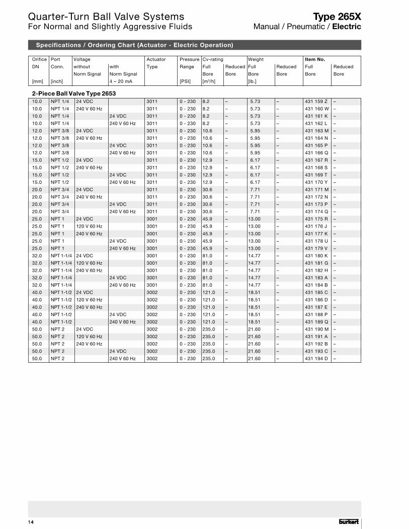
Orifice Port Voltage Actuator Pressure Cv-rating Weight Item No.
DN Conn. without with Type Range Full Reduced Full Reduced Full Reduced
Norm Signal Norm Signal Bore Bore Bore Bore Bore Bore
[mm] [inch] 4 – 20 mA [PSI] [m3/h] [lb.]
2-Piece Ball Valve Type 265310.0 NPT 1/4 24 VDC 3011 0 - 230 8.2 – 5.73 – 431 159 Z –
10.0 NPT 1/4 240 V 60 Hz 3011 0 - 230 8.2 – 5.73 – 431 160 W –
10.0 NPT 1/4 24 VDC 3011 0 - 230 8.2 – 5.73 – 431 161 K –
10.0 NPT 1/4 240 V 60 Hz 3011 0 - 230 8.2 – 5.73 – 431 162 L –
12.0 NPT 3/8 24 VDC 3011 0 - 230 10.6 – 5.95 – 431 163 M –
12.0 NPT 3/8 240 V 60 Hz 3011 0 - 230 10.6 – 5.95 – 431 164 N –
12.0 NPT 3/8 24 VDC 3011 0 - 230 10.6 – 5.95 – 431 165 P –
12.0 NPT 3/8 240 V 60 Hz 3011 0 - 230 10.6 – 5.95 – 431 166 Q –
15.0 NPT 1/2 24 VDC 3011 0 - 230 12.9 – 6.17 – 431 167 R –
15.0 NPT 1/2 240 V 60 Hz 3011 0 - 230 12.9 – 6.17 – 431 168 S –
15.0 NPT 1/2 24 VDC 3011 0 - 230 12.9 – 6.17 – 431 169 T –
15.0 NPT 1/2 240 V 60 Hz 3011 0 - 230 12.9 – 6.17 – 431 170 Y –
20.0 NPT 3/4 24 VDC 3011 0 - 230 30.6 – 7.71 – 431 171 M –
20.0 NPT 3/4 240 V 60 Hz 3011 0 - 230 30.6 – 7.71 – 431 172 N –
20.0 NPT 3/4 24 VDC 3011 0 - 230 30.6 – 7.71 – 431 173 P –
20.0 NPT 3/4 240 V 60 Hz 3011 0 - 230 30.6 – 7.71 – 431 174 Q –
25.0 NPT 1 24 VDC 3001 0 - 230 45.9 – 13.00 – 431 175 R –
25.0 NPT 1 120 V 60 Hz 3001 0 - 230 45.9 – 13.00 – 431 176 J –
25.0 NPT 1 240 V 60 Hz 3001 0 - 230 45.9 – 13.00 – 431 177 K –
25.0 NPT 1 24 VDC 3001 0 - 230 45.9 – 13.00 – 431 178 U –
25.0 NPT 1 240 V 60 Hz 3001 0 - 230 45.9 – 13.00 – 431 179 V –
32.0 NPT 1-1/4 24 VDC 3001 0 - 230 81.0 – 14.77 – 431 180 K –
32.0 NPT 1-1/4 120 V 60 Hz 3001 0 - 230 81.0 – 14.77 – 431 181 G –
32.0 NPT 1-1/4 240 V 60 Hz 3001 0 - 230 81.0 – 14.77 – 431 182 H –
32.0 NPT 1-1/4 24 VDC 3001 0 - 230 81.0 – 14.77 – 431 183 A –
32.0 NPT 1-1/4 240 V 60 Hz 3001 0 - 230 81.0 – 14.77 – 431 184 B –
40.0 NPT 1-1/2 24 VDC 3002 0 - 230 121.0 – 18.51 – 431 185 C –
40.0 NPT 1-1/2 120 V 60 Hz 3002 0 - 230 121.0 – 18.51 – 431 186 D –
40.0 NPT 1-1/2 240 V 60 Hz 3002 0 - 230 121.0 – 18.51 – 431 187 E –
40.0 NPT 1-1/2 24 VDC 3002 0 - 230 121.0 – 18.51 – 431 188 P –
40.0 NPT 1-1/2 240 V 60 Hz 3002 0 - 230 121.0 – 18.51 – 431 189 Q –
50.0 NPT 2 24 VDC 3002 0 - 230 235.0 – 21.60 – 431 190 M –
50.0 NPT 2 120 V 60 Hz 3002 0 - 230 235.0 – 21.60 – 431 191 A –
50.0 NPT 2 240 V 60 Hz 3002 0 - 230 235.0 – 21.60 – 431 192 B –
50.0 NPT 2 24 VDC 3002 0 - 230 235.0 – 21.60 – 431 193 C –
50.0 NPT 2 240 V 60 Hz 3002 0 - 230 235.0 – 21.60 – 431 194 D –
Specifications / Ordering Chart (Actuator - Electric Operation)
Type 265XManual / Pneumatic / Electric
Quarter-Turn Ball Valve SystemsFor Normal and Slightly Aggressive Fluids
15
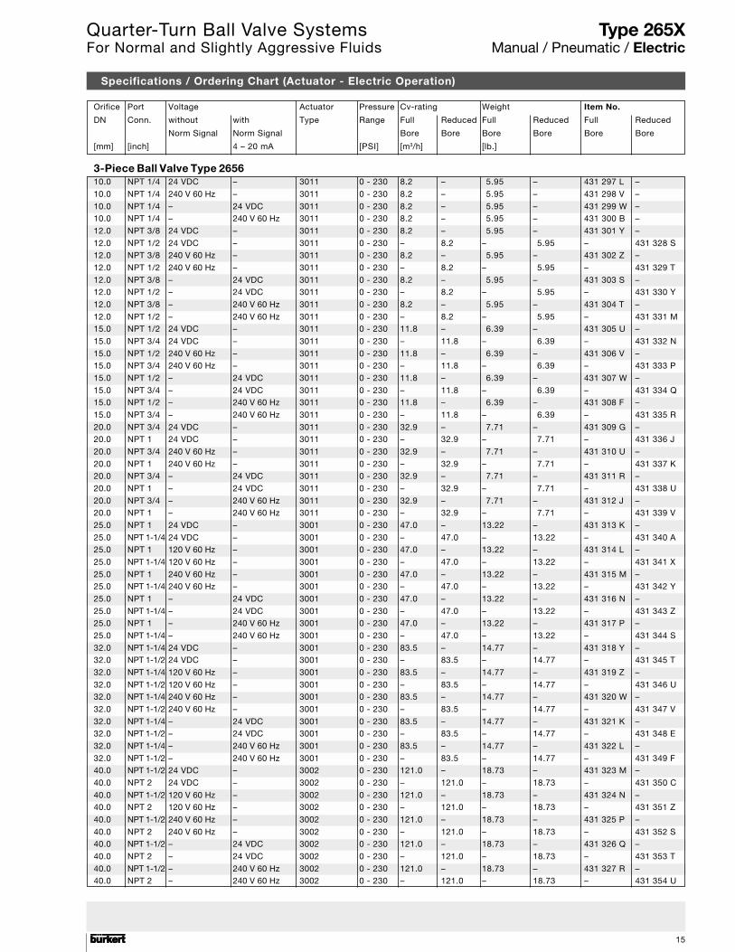
Orifice Port Voltage Actuator Pressure Cv-rating Weight Item No.
DN Conn. without with Type Range Full Reduced Full Reduced Full Reduced
Norm Signal Norm Signal Bore Bore Bore Bore Bore Bore
[mm] [inch] 4 – 20 mA [PSI] [m3/h] [lb.]
3-Piece Ball Valve Type 265610.0 NPT 1/4 24 VDC – 3011 0 - 230 8.2 – 5.95 – 431 297 L –
10.0 NPT 1/4 240 V 60 Hz – 3011 0 - 230 8.2 – 5.95 – 431 298 V –
10.0 NPT 1/4 – 24 VDC 3011 0 - 230 8.2 – 5.95 – 431 299 W –10.0 NPT 1/4 – 240 V 60 Hz 3011 0 - 230 8.2 – 5.95 – 431 300 B –
12.0 NPT 3/8 24 VDC – 3011 0 - 230 8.2 – 5.95 – 431 301 Y –
12.0 NPT 1/2 24 VDC – 3011 0 - 230 – 8.2 – 5.95 – 431 328 S12.0 NPT 3/8 240 V 60 Hz – 3011 0 - 230 8.2 – 5.95 – 431 302 Z –
12.0 NPT 1/2 240 V 60 Hz – 3011 0 - 230 – 8.2 – 5.95 – 431 329 T
12.0 NPT 3/8 – 24 VDC 3011 0 - 230 8.2 – 5.95 – 431 303 S –12.0 NPT 1/2 – 24 VDC 3011 0 - 230 – 8.2 – 5.95 – 431 330 Y
12.0 NPT 3/8 – 240 V 60 Hz 3011 0 - 230 8.2 – 5.95 – 431 304 T –
12.0 NPT 1/2 – 240 V 60 Hz 3011 0 - 230 – 8.2 – 5.95 – 431 331 M15.0 NPT 1/2 24 VDC – 3011 0 - 230 11.8 – 6.39 – 431 305 U –
15.0 NPT 3/4 24 VDC – 3011 0 - 230 – 11.8 – 6.39 – 431 332 N
15.0 NPT 1/2 240 V 60 Hz – 3011 0 - 230 11.8 – 6.39 – 431 306 V –15.0 NPT 3/4 240 V 60 Hz – 3011 0 - 230 – 11.8 – 6.39 – 431 333 P
15.0 NPT 1/2 – 24 VDC 3011 0 - 230 11.8 – 6.39 – 431 307 W –
15.0 NPT 3/4 – 24 VDC 3011 0 - 230 – 11.8 – 6.39 – 431 334 Q15.0 NPT 1/2 – 240 V 60 Hz 3011 0 - 230 11.8 – 6.39 – 431 308 F –
15.0 NPT 3/4 – 240 V 60 Hz 3011 0 - 230 – 11.8 – 6.39 – 431 335 R
20.0 NPT 3/4 24 VDC – 3011 0 - 230 32.9 – 7.71 – 431 309 G –20.0 NPT 1 24 VDC – 3011 0 - 230 – 32.9 – 7.71 – 431 336 J
20.0 NPT 3/4 240 V 60 Hz – 3011 0 - 230 32.9 – 7.71 – 431 310 U –
20.0 NPT 1 240 V 60 Hz – 3011 0 - 230 – 32.9 – 7.71 – 431 337 K20.0 NPT 3/4 – 24 VDC 3011 0 - 230 32.9 – 7.71 – 431 311 R –
20.0 NPT 1 – 24 VDC 3011 0 - 230 – 32.9 – 7.71 – 431 338 U
20.0 NPT 3/4 – 240 V 60 Hz 3011 0 - 230 32.9 – 7.71 – 431 312 J –20.0 NPT 1 – 240 V 60 Hz 3011 0 - 230 – 32.9 – 7.71 – 431 339 V
25.0 NPT 1 24 VDC – 3001 0 - 230 47.0 – 13.22 – 431 313 K –
25.0 NPT 1-1/4 24 VDC – 3001 0 - 230 – 47.0 – 13.22 – 431 340 A25.0 NPT 1 120 V 60 Hz – 3001 0 - 230 47.0 – 13.22 – 431 314 L –
25.0 NPT 1-1/4 120 V 60 Hz – 3001 0 - 230 – 47.0 – 13.22 – 431 341 X
25.0 NPT 1 240 V 60 Hz – 3001 0 - 230 47.0 – 13.22 – 431 315 M –25.0 NPT 1-1/4 240 V 60 Hz – 3001 0 - 230 – 47.0 – 13.22 – 431 342 Y
25.0 NPT 1 – 24 VDC 3001 0 - 230 47.0 – 13.22 – 431 316 N –
25.0 NPT 1-1/4 – 24 VDC 3001 0 - 230 – 47.0 – 13.22 – 431 343 Z25.0 NPT 1 – 240 V 60 Hz 3001 0 - 230 47.0 – 13.22 – 431 317 P –
25.0 NPT 1-1/4 – 240 V 60 Hz 3001 0 - 230 – 47.0 – 13.22 – 431 344 S
32.0 NPT 1-1/4 24 VDC – 3001 0 - 230 83.5 – 14.77 – 431 318 Y –32.0 NPT 1-1/2 24 VDC – 3001 0 - 230 – 83.5 – 14.77 – 431 345 T
32.0 NPT 1-1/4 120 V 60 Hz – 3001 0 - 230 83.5 – 14.77 – 431 319 Z –
32.0 NPT 1-1/2 120 V 60 Hz – 3001 0 - 230 – 83.5 – 14.77 – 431 346 U32.0 NPT 1-1/4 240 V 60 Hz – 3001 0 - 230 83.5 – 14.77 – 431 320 W –
32.0 NPT 1-1/2 240 V 60 Hz – 3001 0 - 230 – 83.5 – 14.77 – 431 347 V
32.0 NPT 1-1/4 – 24 VDC 3001 0 - 230 83.5 – 14.77 – 431 321 K –32.0 NPT 1-1/2 – 24 VDC 3001 0 - 230 – 83.5 – 14.77 – 431 348 E
32.0 NPT 1-1/4 – 240 V 60 Hz 3001 0 - 230 83.5 – 14.77 – 431 322 L –
32.0 NPT 1-1/2 – 240 V 60 Hz 3001 0 - 230 – 83.5 – 14.77 – 431 349 F40.0 NPT 1-1/2 24 VDC – 3002 0 - 230 121.0 – 18.73 – 431 323 M –
40.0 NPT 2 24 VDC – 3002 0 - 230 – 121.0 – 18.73 – 431 350 C
40.0 NPT 1-1/2 120 V 60 Hz – 3002 0 - 230 121.0 – 18.73 – 431 324 N –40.0 NPT 2 120 V 60 Hz – 3002 0 - 230 – 121.0 – 18.73 – 431 351 Z
40.0 NPT 1-1/2 240 V 60 Hz – 3002 0 - 230 121.0 – 18.73 – 431 325 P –
40.0 NPT 2 240 V 60 Hz – 3002 0 - 230 – 121.0 – 18.73 – 431 352 S40.0 NPT 1-1/2 – 24 VDC 3002 0 - 230 121.0 – 18.73 – 431 326 Q –
40.0 NPT 2 – 24 VDC 3002 0 - 230 – 121.0 – 18.73 – 431 353 T
40.0 NPT 1-1/2 – 240 V 60 Hz 3002 0 - 230 121.0 – 18.73 – 431 327 R –40.0 NPT 2 – 240 V 60 Hz 3002 0 - 230 – 121.0 – 18.73 – 431 354 U
Specifications / Ordering Chart (Actuator - Electric Operation)
Type 265XManual / Pneumatic / Electric
Quarter-Turn Ball Valve SystemsFor Normal and Slightly Aggressive Fluids
1616
In case of special requirementsplease consult for advice.
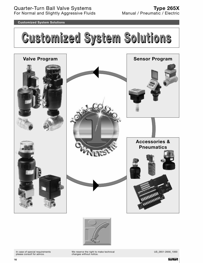
Valve Program Sensor Program
Accessories &Pneumatics
Customized System SolutionsCustomized System SolutionsCustomized System Solutions
Type 265XManual / Pneumatic / Electric
US_2651-2656_1000We reserve the right to make technicalchanges without notice.
JLL
IAC SL