Quantum Zero owner’s Manual
32
Quantum Zero owner’s Manual
Transcript of Quantum Zero owner’s Manual

Quantum Zero owner’s Manual


Quantum Zero owner’s Manual

Quantum Racing Services Ltd. Station Approach Industrial Estate Pulborough, West Sussex, RH20 1AQ
quantumracing.co.uk
First published January 2014
© 2014 Quantum Racing Services Ltd.
Text and illustrations Laurence Wilson Quantum Racing Services Ltd.
Published by Quantum Racing Services Ltd.
Printed and bound in Great Britain by Solopress.com
All rights reserved. No part of this publication may be reproduced in any form or by any means without the prior written permission of Quantum Racing Services Ltd.


9 Introduction 10 Damping curves 13 Basic operation 22 External adjustment 27 Routine maintenance
9 Introduction 10 Damping curves 13 Basic operation 22 External adjustment 27 Routine maintenance


QuANTum ZERo oWNER’S mANuAL | 9
Congratulations and thank you for purchasing Zero shock absorbers from Quantum.
We recommend you read this manual thoroughly before making any adjustments to your shocks.
Zero is a family of mono-tube shock absorbers with one or two ways of adjustment—upgrades that can also be applied to the basic non-adjustable.
Quantum was the first to introduce to Formula 1 a two-way adjustable mono-tube shock absorber without reservoir canister that was entirely adjustable on the car.
The Quantum Two.Zero is the latest evolution of that game changing design.
The Two.Zero offers independent external adjustment of compression and rebound damping. This is made possible by placing two adjusters inside the shaft.
Placing the adjusters inside the shaft puts them in parallel with the piston. This is the best location for an effective adjuster.
Any valve or adjuster that acts across the piston affects an area with a diameter equal to that of the piston—unlike the valve or adjuster inside a base valve or reservoir canister that affects an area with a diameter equal to that of the shaft.
This is doubly important because the effective area is proportional to the volume of oil that will flow through the adjuster and the pressure inside the shock absorber.
Increasing the volume of oil available to the adjuster means the adjuster can be made bigger, thereby making it less sensitive to manufacturing tolerances.
Increasing the area the adjuster acts upon reduces the pressure inside the shock absorber, allowing it to respond quicker to small movements and high frequencies.
All Quantum shock absorbers are based upon this simple idea.
This manual describes the operation and care of Quantum Zero shock absorbers—the Zero, one.Zero and Two.Zero. They are entirely self-contained and do not require a reservoir canister or base valve for the purposes of external adjustment or compression damping.
Introduction

10 | © 2014 QuANTum RAcING SERvIcES LTd.
Damping curvesWhen describing the operation of a shock absorber it is often helpful to understand how information is displayed on a dyno plot—the force vs. velocity curve produced by a shock absorber dynamometer.
Shock absorbers are essentially timing devices. They are unable to support the weight of a vehicle alone but will influence how quickly the vehicle settles on its springs.
Hydraulic shock absorbers are velocity sensitive. The force with which they resist movement varies with velocity. How this force varies is entirely dependent upon the configuration of the shock absorber.
The force experienced at the shaft is the result of a pressure differential inside the shock absorber. A pressure differential occurs when oil is forced to flow through small apertures inside the shock absorber.
A simple force vs. velocity curve can be divided in two: low-speed damping below the knee and high-speed damping above the knee (Fig. 1-1).
Low-speed damping is affected by bleed. Bleed occurs through any orifice that does not vary in size during operation, such as a drilled hole.
A bleed of fixed diameter will always produce a progressive damping curve. If there are no
other valves, the force will increase exponentially and there will be no knee and no high-speed transition (Fig. 1-2).
Adjusting the bleed or the diameter of the hole affects the rate at which low-speed damping force increases in kg/mms2 between 0kg and the knee (Fig. 1-3).
high-speedlow-speed
knee
Fig. 1-1
Fig. 1-2
Fig. 1-3

QuANTum ZERo oWNER’S mANuAL | 11
High-speed damping is affected by flow through a pre-loaded valve. It begins when the pressure differential inside the shock absorber is sufficient to open the valve.
If the pre-load applied to the valve can be adjusted, the force at which the valve opens can also be adjusted (Fig. 1-4).
The open area of the valve governs the rate at which high-speed damping force increases in kg/mms2—just as it does for low-speed damping.
A small poppet might only reduce the rate at which
the damping force continues to increase, whereas a large annular shim seat may cause the damping curve to ‘flat-line’.
damping curves that show little or no change in rate we refer to as being linear. damping curves that fall dramatically we call digressive (Fig. 1-5).
When both axes of the graph are taken out to infinity, it can be seen that even a pre-loaded valve will produce a progressive damping curve (Fig. 1-6).
The bleeds and valves that define the shape of the compression-damping curve do not need to be the same ones that define the rebound-damping curve. This means the compression and rebound
curves can be different.
The two curves will often be illustrated on the same graph with positive and negative force and velocity in positive units only (Fig. 1-7).
The shock absorber will also exhibit different characteristics as it accelerates and decelerates. The accelerating force values will be lower than the decelerating force values as the shock absorber changes direction, i.e. at zero velocity (Fig. 1-8).
Fig. 1-4
linea
r
digressive
Fig. 1-5
low-speed curve
high-speed curve
Fig. 1-6
compression damping
rebound damping
Fig. 1-7

12 | © 2014 QuANTum RAcING SERvIcES LTd.
Separation between the accelerating and decelerating curves occurs as pressure equalizes inside the shock absorber. This is called hysteresis.
It is desirable to reduce hysteresis to a minimum but where steep low-speed curves are preferred, hysteresis must be accepted as inevitable.
Note: In order to compare hysteresis between two shock absorbers it is necessary to replicate test conditions. Peak velocity and stroke must be the same as well as adjuster position.
Note: Hysteresis can be characterized as a delay in build up and release of pressure when the shock absorber changes direction. It is particularly harmful to high frequency short stroke operation. If the pressure inside the shock absorber is unable to equalize sufficiently quickly, the shock absorber may provide little or no damping immediately after it has changed direction.
Hysteresis is the result of compressibility in the shock oil, gases dissolved in the shock oil and even flex in the components. It is at its worst when the differential pressure is high—especially if the bleed adjusters are closed.
Shock absorber manufacturers will look to reduce the effects of hysteresis by increasing the effective area of the valves. This can be explained by the equation:
Force = Pressure × Area
The pressure inside the shock absorber can be reduced if the area the valve acts upon is increased. This can be achieved by increasing the diameter of the piston. Nonetheless, where a reservoir canister or base valve is used for external adjustment or compression damping, the shaft becomes the piston—and because the effective area is so small, the pressure differential must necessarily be high.
Hysteresis is inevitable but it can be alleviated by good design. The best solution is to manage all damping across the piston—as we do at Quantum.
accelerating curve
decelerating curve
Fig. 1-8

QuANTum ZERo oWNER’S mANuAL | 13
Basic operationThe Quantum Zero, One.Zero and Two.Zero belong to a family of mono-tube shock absorbers with excellent interchangeability of parts. What follows is a brief description of the operation of these shock absorbers.
Figures referred to in the text can be found at the end of the chapter.
The inside of the shock absorber can be divided into three chambers: the compression chamber (Fig. 2-1.A, Fig. 2-3.A, Fig. 2-5.A), the rebound chamber (Fig. 1.B, Fig. 2-3.B, Fig. 2-5.B) and the gas chamber (Fig. 2-1.c, Fig. 2-3.c, Fig. 2-5.c).
The piston separates the compression and rebound chambers. These contain oil.
The gas chamber contains nitrogen. This is kept separate from the oil behind the floating piston.
At rest, the pressure inside all of the chambers is equal. All the time the shock absorber is fully extended this will be consistent with the recommended gas pressure.
When the shock absorber is caused to move, the piston moves through the oil. In doing so, oil must flow through the piston. The restriction of the valves will cause a pressure differential either side of the piston.
In compression, pressure inside the rebound chamber will decrease. In extension, pressure inside the rebound chamber will increase. At all times the pressure inside the compression chamber will remain consistent with that inside the gas chamber.
Note: Gas pressure should be greater than the maximum anticipated operating pressure to ensure proper operation.
CompressionAs the shock absorber is compressed the shaft moves into the body and the piston moves through the oil. This causes the volume inside each of the chambers to change. The compression chamber and the gas chamber will reduce in size. The rebound chamber will increase in size.
The amount of oil that must flow through the piston—and thereby the change in volume inside the compression and rebound chambers—is equal to:
change in volume = (Pi × Radius of the piston2 − Pi × Radius of the shaft2) × Travel

14 | © 2014 QuANTum RAcING SERvIcES LTd.
The shaft displaces a volume of oil. This is compensated for by a reduction in size of the gas chamber. The change in volume of the gas chamber is equal to:
change in volume = Pi × Radius of the shaft2 × Travel
i. Zero: Negative pressure inside the rebound chamber causes oil to flow through the bleed jet. The diameter of the jet causes a restriction. The jet is of fixed diameter and cannot be adjusted externally.
oil flows through the jet (Fig. 2-1.d) and into the rebound chamber via cross-drillings in the shaft (Fig. 2-1.E).
i. One.Zero: Negative pressure inside the rebound chamber causes oil to flow through the bleed jet. A restriction occurs where the oil passes between the jet and the needle.
oil flows through the jet (Fig. 2-3.d) and around the needle (Fig. 2-3.E). It enters the rebound chamber via cross-drillings in the shaft.
It is possible to adjust the restriction externally. Turning the adjuster clockwise introduces the needle further into the jet, increasing the restriction.
i. Two.Zero: Negative pressure inside the rebound chamber causes the Rd check shim to open (Fig. 2-5.d) and the cd check shim to close (Fig. 2-5.E). oil flows through drillings in the perimeter of the Rd jet (Fig. 2-5.F), bypassing the Rd needle. A restriction occurs where the oil passes between the cd needle and
its jet (Fig. 2-5.G). The oil enters the rebound chamber via cross-drillings in the shaft.
It is possible to adjust the restriction externally. Turning the cd adjuster clockwise introduces the cd needle further into the jet, increasing the restriction.
ii. All variants: As the velocity of the shaft increases, so too does the difference in pressure inside the shock absorber.
When the difference in pressure becomes sufficient, the compression-damping valve stack on the backside of the piston opens. The specific pressure is determined by the choice of piston and the quantity and thickness of the shims.
oil flows around the rebound-damping valve stack and through the piston. A build up of pressure on the back of the compression-damping valve stack causes the valve stack to deflect (Fig. 2-1.F, Fig. 2-3.F, Fig. 2-5.H) and the oil enters the rebound chamber.
ReboundAs the shock absorber extends the shaft moves out of the body and the piston moves through the oil. This causes the volume inside each of the chambers to change. The compression chamber and the gas chamber will increase in size. The rebound chamber will reduce in size.
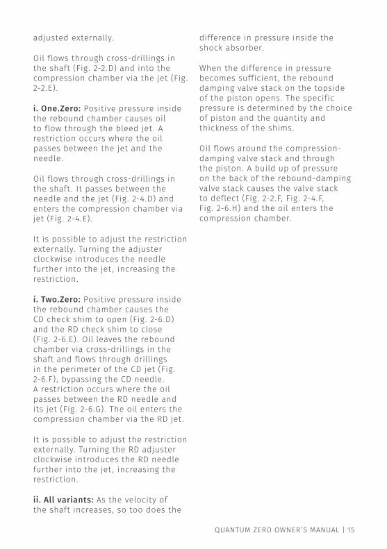
i. Zero: Positive pressure inside the rebound chamber causes oil to flow through the bleed jet. The diameter of the jet causes a restriction. The jet is fixed diameter and cannot be
QuANTum ZERo oWNER’S mANuAL | 15
adjusted externally.
oil flows through cross-drillings in the shaft (Fig. 2-2.d) and into the compression chamber via the jet (Fig. 2-2.E).
i. One.Zero: Positive pressure inside the rebound chamber causes oil to flow through the bleed jet. A restriction occurs where the oil passes between the jet and the needle.
oil flows through cross-drillings in the shaft. It passes between the needle and the jet (Fig. 2-4.d) and enters the compression chamber via jet (Fig. 2-4.E).
It is possible to adjust the restriction externally. Turning the adjuster clockwise introduces the needle further into the jet, increasing the restriction.
i. Two.Zero: Positive pressure inside the rebound chamber causes the cd check shim to open (Fig. 2-6.d) and the Rd check shim to close (Fig. 2-6.E). oil leaves the rebound chamber via cross-drillings in the shaft and flows through drillings in the perimeter of the cd jet (Fig. 2-6.F), bypassing the cd needle. A restriction occurs where the oil passes between the Rd needle and its jet (Fig. 2-6.G). The oil enters the compression chamber via the Rd jet.
It is possible to adjust the restriction externally. Turning the Rd adjuster clockwise introduces the Rd needle further into the jet, increasing the restriction.
ii. All variants: As the velocity of the shaft increases, so too does the
difference in pressure inside the shock absorber.
When the difference in pressure becomes sufficient, the rebound damping valve stack on the topside of the piston opens. The specific pressure is determined by the choice of piston and the quantity and thickness of the shims.
oil flows around the compression-damping valve stack and through the piston. A build up of pressure on the back of the rebound-damping valve stack causes the valve stack to deflect (Fig. 2-2.F, Fig. 2-4.F, Fig. 2-6.H) and the oil enters the compression chamber.

FIG. 2-1

FIG 2-2

FIG. 2-3

FIG. 2-4

FIG. 2-5

FIG. 2-6

22 | © 2014 QuANTum RAcING SERvIcES LTd.
External adjustmentQuantum One.Zero and Two.Zero shock absorbers are externally adjustable. Adjustment is made by turning a knurled collar—or clicker—on the top eye.
Quantum One.ZeroThe Quantum one.Zero is one-way adjustable. It has a single clicker on the top eye. Adjustment affects both compression and rebound damping.
LoW-SPEEd AdJuSTERType: Bleed adjusterAffects: Bleed across the piston
in both directionsEffective area: 1,185.7mm2
Number of clicks: 24±1Full stiff: Position 0, fully
clockwise
Note: The effective area can be calculated using the following equation:
Effective area = Pi × Radius of the piston2 − Pi × Radius of the shaft2
It is equal to the volume of fluid that will pass through the adjuster for one unit length of travel.

QuANTum ZERo oWNER’S mANuAL | 23

24 | © 2014 QuANTum RAcING SERvIcES LTd.
Quantum Two.ZeroThe Quantum Two.Zero is two-way adjustable. It has two clickers on the top eye. The clicker nearest the shaft affects compression. The clicker furthest from the shaft affects rebound.
LoW-SPEEd comPRESSIoN AdJuSTERType: Bleed adjusterAffects: Bleed across the
piston in compression only
Identification: The clicker nearest the shaft
Effective area: 1,185.7mm2
Number of clicks: 24±1Full stiff: Position 0, fully
clockwise
LoW-SPEEd REBouNd AdJuSTERType: Bleed adjusterAffects: Bleed across the
piston in rebound onlyIdentification: The clicker furthest
from the shaftEffective area: 1,185.7mm2
Number of clicks: 24±1Full stiff: Position 0, fully
clockwise

QuANTum ZERo oWNER’S mANuAL | 25

26 | © 2014 QuANTum RAcING SERvIcES LTd.
Low-speed adjuster effect on the damping curveQuantum one.Zero and Two.Zero shock absorbers are low-speed adjustable. This means the rate at which damping force increases in kg/mms2 between 0kg and the knee can be adjusted externally (Fig. 3-1).
Note: The shape of the damping curve and the range of adjustment are heavily influenced by the choice of piston and the internal valving. The illustration should be considered an aid to understanding only.
Adjustment affects the open area of the bleed jet. The one.Zero has one bleed jet that affects both compression and rebound damping. The Two.Zero has two bleed jets that affect compression and rebound damping independently.
The adjuster inside the one.Zero comprises a needle and a jet. The jet has a hole with a fixed diameter. The needle is the same diameter as the hole at its base and tapers to a point at its tip.
The needle faces into the jet. An adjuster rod passes through the shaft and contacts the back of the needle on one end and a cross-pin in the clicker on the other. Turning the clicker clockwise introduces the needle further into the jet, thereby reducing the open area and further restricting flow.
The Two.Zero has two needles and two jets. Both jets have the same open area, which is the same as the single jet in the one.Zero. Each jet flows in one direction only.
Note: All adjustment should be made from position 0, full stiff. At this position the needle will bottom out in the jet. Full soft is not so clearly defined as the total number of clicks can vary due to manufacturing tolerances.
Note: Do not force the clickers past full stiff of full soft. Doing so could damage the adjuster. Do not use any tools to adjust the clicker, e.g. pipe grips, mole grips, etc.
Position 0 — full stiff
Position 24 — full soft
Fig. 3-1

QuANTum ZERo oWNER’S mANuAL | 27
Routine maintenanceWith proper care and maintenance, your Quantum shocks should prove exceptionally durable.
Service intervals are difficult to predict as environmental conditions can vary wildly. Shock absorbers subjected to road dirt and grime and those near the exhaust will require more regular servicing than those protected from the elements on top of the pedal box.
We suggest that you visually inspect the shocks regularly and observe the following recommendations:
• Keep the shock absorbers clean and dry. The shaft bearing is fitted with a wiper seal but it is effective only in preventing foreign materials from being drawn into the shock absorber. It will not prevent dirt from accumulating around the shaft. If this is allowed to happen the risk of damage to the shaft is increased. Keeping the shocks clean and dry makes it easier to identify leaks.
• Try to keep the shock absorbers cool. make every effort to keep the temperature equal across axle pairs. If one shock runs hotter than the other—be this because it is closer to the exhaust or for any other reason—direct air onto the shock
absorber to cool it down.
• Periodically inspect the spherical joints for play. The ball should be tight in the housing.
• do not allow the shaft to rust. The shaft is hard chrome plated and will resist corrosion well but it is advisable to lubricate it regularly with Wd40 or similar penetrating oil—particularly underneath the bump rubber and around the eyelet base where moisture can collect.
• do not attempt to adjust the height of the spring platform without first removing loose dirt from the body.
dyno testing your shock absorbers is the only acceptable means to determine if they are performing as expected. Shocks should always be tested in pairs—where this applies—to be sure they match.
over a period of time the oil inside the shock absorber will degrade. As the bore of the shock absorber wears, microscopically small particles of aluminium become suspended in the oil. If the intervals between servicing are too great, this can cause accelerated wear.
only by opening the shock absorber can the condition of the oil and the internal components be assessed. If the oil has blackened or smells bad, it should be changed.

28 | © 2014 QuANTum RAcING SERvIcES LTd.
All Quantum shock absorbers are supplied with motul 5W shock oil. This is the only oil we recommend.
With regular servicing there should be no reason not to expect an exceptional service life.


Quantum is committed to a policy of continuous product development and reserves the right to make changes to specifications and prices without prior notice. The illustrations contained within depict generic designs. Some
external features and other details may differ from the product supplied. The information in this manual can therefore be given as guidance only. While Quantum makes every effort to ensure that specifications are accurate at
the time of publication, you should always check with your authorised distributor for up-to-date information.
Your Quantum shock absorbers were supplied by: