QUANTUM INFORMATION PROCESSING 2015 © The Authors,...
8
QUANTUM INFORMATION PROCESSING Experimental scattershot boson sampling Marco Bentivegna, 1 Nicolò Spagnolo, 1 Chiara Vitelli, 1,2 Fulvio Flamini, 1 Niko Viggianiello, 1 Ludovico Latmiral, 1 Paolo Mataloni, 1 Daniel J. Brod, 3 Ernesto F. Galvão, 4 Andrea Crespi, 5,6 Roberta Ramponi, 5,6 Roberto Osellame, 5,6 Fabio Sciarrino 1 * Boson sampling is a computational task strongly believed to be hard for classical computers, but efficiently solvable by orchestrated bosonic interference in a specialized quantum computer. Current experimental schemes, however, are still insufficient for a convincing demonstration of the advantage of quantum over classical computation. A new variation of this task, scattershot boson sampling, leads to an exponential increase in speed of the quantum device, using a larger number of photon sources based on parametric down-conversion. This is achieved by having multiple heralded single photons being sent, shot by shot, into different random input ports of the interferometer. We report the first scattershot boson sampling experiments, where six different photon-pair sources are coupled to integrated photonic circuits. We use recently proposed statistical tools to analyze our experimental data, providing strong evidence that our photonic quantum simulator works as expected. This approach represents an important leap toward a convincing experimental demonstration of the quantum computational supremacy. INTRODUCTION Theory has shown that quantum computers should be able to markedly outperform conventional, classical computers in specific tasks (1). In practice, however, no quantum computer has yet solved a problem instance which is hard to solve classically. With the goal of rigorously establishing what was called quantum supremacy, in 2010 Aaronson and Arkhipov provided strong theoretical evidence that a simpler, specialized quantum computer could solve a classically hard computational task (2). The so-called boson sampling problem con- sists of sampling from the output distribution of n indistinguishable photons entering different input modes of a given m-mode random in- terferometer (see Fig. 1A). The complex multiphoton interference within the device was shown, under mild computational assumptions, to yield an output distribution that is hard to sample using classical computers. The difficulty has been traced back to the known intractability of calcu- lating the permanent function of a matrix (3). Indeed, each output’s probability amplitude is given by the permanent of a different n × n matrix obtained from the m × m unitary matrix U describing the inter- ferometer (2, 4, 5). Because a photonic boson sampling computer does not use adapt- ive measurements, it falls short of the requirements (6, 7) for a uni- versal quantum computer capable, for example, of factoring integers efficiently (8). On the other hand, its comparatively simple design has prompted a number of small-scale implementations using the interfer- ence of three photons injected over different modes in integrated in- terferometers with up to 13 modes (9–15). First estimates have shown that 30 photons evolving in an interferometer with about 100 modes would already be extremely demanding to simulate classically, provid- ing strong experimental evidence for the quantum computational su- premacy. Moreover, boson sampling is an experimental platform suitable for addressing important intermediate challenges for the field of quantum computation, such as benchmarking and certification of medium-scale devices (14–17). There have been recent theoretical investigations on allowable error tolerances (18, 19), as well as a recent proposal for an implementation using phonons in ion traps (20, 21). The technologies enabling a boson sampling computer are useful also for other photonic applications such as quantum cryptography (22) and universal photonic quantum computation (7, 23). One of the main difficulties in scaling up the complexity of boson sampling devices is the requirement of a reliable source of many in- distinguishable photons. Despite recent advances in photon generation (24) using atoms (25), molecules (26, 27), color centers in diamond (28), and quantum dots (29, 30), currently, the most widely used method remains parametric down-conversion (PDC) (31, 32). This approach requires pumping a nonlinear crystal with an intense laser to generate pairs of identical photons. The main advantages of PDC sources are the high photon indistinguishability, collection efficiency, and rela- tively simple experimental setups. This technique, however, suffers from two drawbacks. First, because the nonlinear process is nondetermi- nistic, so is the photon generation, even though it can be heralded. Sec- ond, the laser pump power, and hence the source’s brilliance, has to be kept low to prevent unwanted higher-order terms in the photon gen- eration process. These two characteristics have, so far, restricted PDC implementations of boson sampling experiments to proof-of-principle demonstrations with three photons only in the original spirit of boson sampling (one photon per mode, injected over different modes). Recently, a new scheme has been proposed to make the best use of PDC sources for photonic boson sampling, greatly enhancing the rate of n-photon events (33, 34). This approach has been named scatter- shot boson sampling in Aaronson’s blog (34) and involves connecting k (k>n) PDC heralded single-photon sources to different input ports of the interferometer (see Fig. 1B). Suppose each PDC source yields a single photon with probability & per pulse. By pumping all k PDC crys- tals with simultaneous laser pulses, n photons will be simultaneously generated in a random (but heralded) set of input ports with probabil- ity k n & n , which, for k ≫ n, represents an exponential improvement in generation rate with respect to usual, fixed-input boson sampling with n sources. The scattershot boson sampling problem, naturally solvable by this setup, is to sample from the output distribution of a 1 Dipartimento di Fisica, Sapienza Università di Roma, Piazzale Aldo Moro 5, I-00185 Roma, Italy. 2 Center of Life NanoScience @ La Sapienza, Istituto Italiano di Tecnologia, Viale Regina Elena, 255, I-00185 Roma, Italy. 3 Perimeter Institute for Theoretical Physics, 31 Caroline Street North, Waterloo, Ontario N2L 2Y5, Canada. 4 Instituto de Física, Univer- sidade Federal Fluminense, Av. Gal. Milton Tavares de Souza s/n, Niterói, Rio de Janeiro 24210-340, Brazil. 5 Istituto di Fotonica e Nanotecnologie, Consiglio Nazionale delle Ricerche, Piazza Leonardo da Vinci, 32, I-20133 Milano, Italy. 6 Dipartimento di Fisica, Politecnico di Milano, Piazza Leonardo da Vinci, 32, I-20133 Milano, Italy. *Corresponding author. E-mail: [email protected] 2015 © The Authors, some rights reserved; exclusive licensee American Association for the Advancement of Science. Distributed under a Creative Commons Attribution NonCommercial License 4.0 (CC BY-NC). 10.1126/sciadv.1400255 RESEARCH ARTICLE Bentivegna et al. Sci. Adv. 2015;1:e1400255 17 April 2015 1 of 7 on February 15, 2019 http://advances.sciencemag.org/ Downloaded from
Transcript of QUANTUM INFORMATION PROCESSING 2015 © The Authors,...

2015 © The Authors, some rights reserved;
R E S EARCH ART I C L E
QUANTUM INFORMAT ION PROCESS ING
nsee American Association forment of Science. Distributed
tive Commons Attribution
cial License 4.0 (CC BY-NC).
dv.1400255
Experimental scattershot boson samplingMarco Bentivegna,1 Nicolò Spagnolo,1 Chiara Vitelli,1,2 Fulvio Flamini,1 Niko Viggianiello,1
Ludovico Latmiral,1 Paolo Mataloni,1 Daniel J. Brod,3 Ernesto F. Galvão,4 Andrea Crespi,5,6
Roberta Ramponi,5,6 Roberto Osellame,5,6 Fabio Sciarrino1*
exclusive lice
the Advance
under a Crea
NonCommer
10.1126/scia
Dow
Boson sampling is a computational task strongly believed to be hard for classical computers, but efficiently solvableby orchestrated bosonic interference in a specialized quantum computer. Current experimental schemes, however,are still insufficient for a convincing demonstration of the advantage of quantum over classical computation. A newvariation of this task, scattershot boson sampling, leads to an exponential increase in speed of the quantum device,using a larger number of photon sources based on parametric down-conversion. This is achieved by havingmultiple heralded single photons being sent, shot by shot, into different random input ports of the interferometer.We report the first scattershot boson sampling experiments, where six different photon-pair sources are coupled tointegrated photonic circuits. We use recently proposed statistical tools to analyze our experimental data, providingstrong evidence that our photonic quantum simulator works as expected. This approach represents an importantleap toward a convincing experimental demonstration of the quantum computational supremacy.
nl
on February 15, 2019http://advances.sciencem
ag.org/oaded from
INTRODUCTION
Theory has shown that quantum computers should be able tomarkedly outperform conventional, classical computers in specifictasks (1). In practice, however, no quantum computer has yet solveda problem instance which is hard to solve classically. With the goal ofrigorously establishing what was called quantum supremacy, in 2010Aaronson and Arkhipov provided strong theoretical evidence that asimpler, specialized quantum computer could solve a classically hardcomputational task (2). The so-called boson sampling problem con-sists of sampling from the output distribution of n indistinguishablephotons entering different input modes of a given m-mode random in-terferometer (see Fig. 1A). The complex multiphoton interference withinthe device was shown, under mild computational assumptions, to yieldan output distribution that is hard to sample using classical computers.The difficulty has been traced back to the known intractability of calcu-lating the permanent function of a matrix (3). Indeed, each output’sprobability amplitude is given by the permanent of a different n × nmatrix obtained from them×m unitarymatrixU describing the inter-ferometer (2, 4, 5).
Because a photonic boson sampling computer does not use adapt-ive measurements, it falls short of the requirements (6, 7) for a uni-versal quantum computer capable, for example, of factoring integersefficiently (8). On the other hand, its comparatively simple design hasprompted a number of small-scale implementations using the interfer-ence of three photons injected over different modes in integrated in-terferometers with up to 13 modes (9–15). First estimates have shownthat 30 photons evolving in an interferometer with about 100 modeswould already be extremely demanding to simulate classically, provid-ing strong experimental evidence for the quantum computational su-premacy. Moreover, boson sampling is an experimental platform
1Dipartimento di Fisica, Sapienza Università di Roma, Piazzale Aldo Moro 5, I-00185 Roma,Italy. 2Center of Life NanoScience @ La Sapienza, Istituto Italiano di Tecnologia, VialeRegina Elena, 255, I-00185 Roma, Italy. 3Perimeter Institute for Theoretical Physics, 31Caroline Street North, Waterloo, Ontario N2L 2Y5, Canada. 4Instituto de Física, Univer-sidade Federal Fluminense, Av. Gal. Milton Tavares de Souza s/n, Niterói, Rio de Janeiro24210-340, Brazil. 5Istituto di Fotonica e Nanotecnologie, Consiglio Nazionale delleRicerche, Piazza Leonardo da Vinci, 32, I-20133 Milano, Italy. 6Dipartimento di Fisica,Politecnico di Milano, Piazza Leonardo da Vinci, 32, I-20133 Milano, Italy.*Corresponding author. E-mail: [email protected]
Bentivegna et al. Sci. Adv. 2015;1:e1400255 17 April 2015
suitable for addressing important intermediate challenges for the fieldof quantum computation, such as benchmarking and certification ofmedium-scale devices (14–17). There have been recent theoreticalinvestigations on allowable error tolerances (18, 19), as well as a recentproposal for an implementation using phonons in ion traps (20, 21).The technologies enabling a boson sampling computer are useful alsofor other photonic applications such as quantum cryptography (22)and universal photonic quantum computation (7, 23).
One of the main difficulties in scaling up the complexity of bosonsampling devices is the requirement of a reliable source of many in-distinguishable photons. Despite recent advances in photon generation(24) using atoms (25), molecules (26, 27), color centers in diamond (28),and quantum dots (29, 30), currently, the most widely used methodremains parametric down-conversion (PDC) (31, 32). This approachrequires pumping a nonlinear crystal with an intense laser to generatepairs of identical photons. The main advantages of PDC sources arethe high photon indistinguishability, collection efficiency, and rela-tively simple experimental setups. This technique, however, suffersfrom two drawbacks. First, because the nonlinear process is nondetermi-nistic, so is the photon generation, even though it can be heralded. Sec-ond, the laser pump power, and hence the source’s brilliance, has to bekept low to prevent unwanted higher-order terms in the photon gen-eration process. These two characteristics have, so far, restricted PDCimplementations of boson sampling experiments to proof-of-principledemonstrations with three photons only in the original spirit of bosonsampling (one photon per mode, injected over different modes).
Recently, a new scheme has been proposed to make the best use ofPDC sources for photonic boson sampling, greatly enhancing the rateof n-photon events (33, 34). This approach has been named scatter-shot boson sampling in Aaronson’s blog (34) and involves connectingk (k > n) PDC heralded single-photon sources to different input portsof the interferometer (see Fig. 1B). Suppose each PDC source yields asingle photon with probability & per pulse. By pumping all k PDC crys-tals with simultaneous laser pulses, n photons will be simultaneouslygenerated in a random (but heralded) set of input ports with probabil-ity
� kn�&n, which, for k≫ n, represents an exponential improvement
in generation rate with respect to usual, fixed-input boson samplingwith n sources. The scattershot boson sampling problem, naturallysolvable by this setup, is to sample from the output distribution of a
1 of 7
R E S EARCH ART I C L E
http://advances.scienD
ownloaded from
given, random interferometer for random sets of input modes. Notethat the pump laser power does not need to be increased k-fold be-cause the laser can sequentially pump each PDC source with very littleloss to down-converted photons. In this way, the ratio between one-pair production rate and higher-order terms can be kept low. Anotherinteresting feature of this scheme is the possibility of recording eventscorresponding to different numbers of injected photons. All thesecharacteristics suggest that the scattershot approach to boson samplingwill be decisive in future, larger experiments designed to reach thequantum supremacy regime.
on February 15, 2019
cemag.org/
RESULTS
Here, we report experimental results of scattershot boson samplingexperiments using a 13-mode integrated photonic chip. We use up tosix PDC photon sources to obtain data corresponding to two- andthree-photon interference, and validate the device’s functioning usingrecently proposed statistical tests (14, 17). Additional results on a differ-ent nine-mode chip are also presented and certified, thus showing therobustness of the scattershot approach. Finally, we use numerical cal-culations to discuss the complexity of boson sampling simulation andcertification, and to estimate a benchmark for quantum supremacy.
Scattershot boson sampling experimentA photonic scattershot boson sampling experiment involves a few ex-perimentally demanding steps (see Fig. 2A). First, k > n PDC sourcesare used to generate n indistinguishable photons in a heralded, butrandom, set of modes. The input state must then be prepared (intro-ducing time delays and polarization compensation) to be injected intothe m-mode integrated interferometer. We must then detect n-foldcoincident photon counts at the chip’s output modes, all the whilemaintaining synchronization so that we have true n-photon interfer-ence in the chip. Finally, it is necessary to analyze the output data tovalidate the correct functioning of the device.
For our experiments, we fabricated two integrated photonic chipsimplementing randommultimode interferometers (with 9 and 13 modes),using a femtosecond laser writing technique (35–38) described in theMethods section. For the nine-mode chip, the input state was created
Bentivegna et al. Sci. Adv. 2015;1:e1400255 17 April 2015
by a four-photon PDC source (crystal Ca in Fig. 2B), with one of thephotons used as a trigger. Our preliminary experiment involved simu-lating the statistics of a scattershot boson sampling experiment in the9-mode chip by manually connecting 20 different sets of input modesto the source, via a fiber array, and uniformly mixing the data corre-sponding to different input states.
We used the 13-mode chip to implement scattershot boson samplingexperiments with a total of six PDC sources (S1 to S6 in Fig. 2B). Wesimplified the implementation by enfolding two equal sources in eachcrystal, corresponding to the two possible vertical/horizontal polariza-tion combinations for the photon pair generated. Hence, the six sourcesS1 to S6 are created using only the three crystals Ca, Cb, and Cg. EachPDC source ideally produces two indistinguishable photons. One suchsource (source S2) prepares photons I and III, which enter the inter-ferometer in fixed modes 6 and 8, respectively. The other five PDCsources produce random, but heralded, single photons, which are cou-pled to different input ports of the chip via a polarization correction stage,delay lines, and a single-mode fiber array, according to the map in Fig.2D. Note that we further increased the input variability by distributingphoton VII randomly among four different input ports via an opticalfiber switcher with switching rate comparable to the obtained exper-imental count rate. This raises from five to eight the number of pos-sible input sets, allowing us validation procedure tests on data sampledfrom a larger number of input-output configurations.
For both chips, the output photons are collected by a multimodefiber array, and multiphoton coincidences are detected by avalanchephotodiodes, coordinated by an electronic data acquisition system ca-pable of registering events with an arbitrary number of photons. Wethen analyzed data corresponding to two- and three-photon interfer-ence inside the chip. Synchronizing up to six PDC sources distributedover 10 input modes is a technically difficult step; once that was achieved,the controllable, relative delays between photons allowed us to adjusttheir degree of distinguishability. Further details about synchroniza-tion procedures and indistinguishability between photons of differentsources are given in the Supplementary Materials.
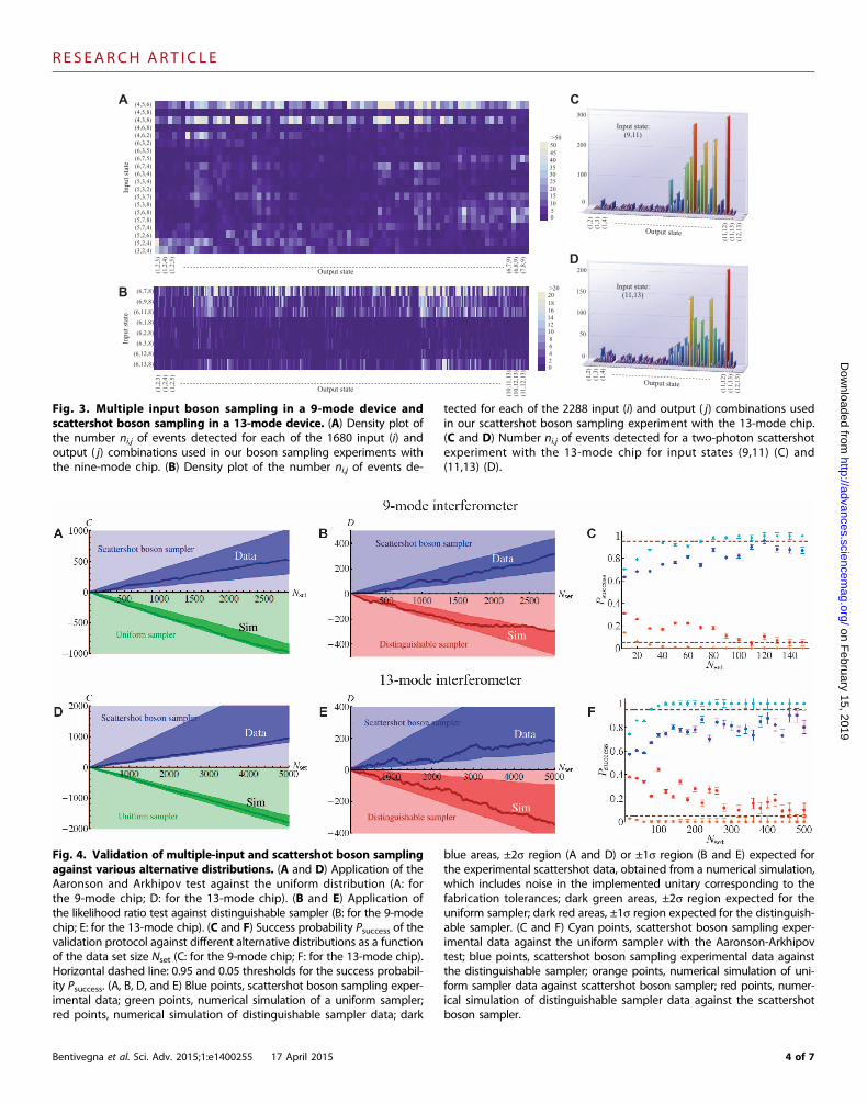
The observed numbers of events corresponding to each input-output combination for the 9- and 13-mode chips are shown in Fig. 3,A and B, respectively. Note the sparseness of the data set, because onlya few events corresponding to each input-output combination are
A B
Linear unitary transformation
Input Output
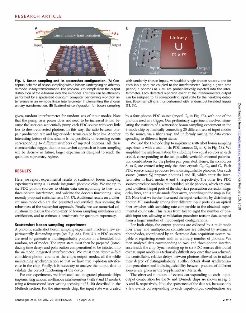
Fig. 1. Boson sampling and its scattershot configuration. (A) Con- with randomly chosen inputs. m heralded single-photon sources, one for
ceptual scheme of boson sampling with n bosons undergoing an arbitrarym-mode unitary transformation. The problem is to sample from the outputdistribution of the n-bosons over the m-modes. This task can be efficientlyperformed by a specialized quantum computer performing n-photon in-terference in an m-mode linear interferometer implementing the chosenunitary transformation. (B) Scattershot configuration for boson samplingeach input port, are coupled to the interferometer. During a given timeperiod, n photons (n < m) are probabilistically injected into the inter-ferometer. Each detected n-photon event at the interferometer’s outputcan be assigned to its corresponding input state by the heralding detec-tors. Boson sampling is thus performed with random, but heralded, inputs(33, 34).
2 of 7

R E S EARCH ART I C L E
on February 15, 2019
http://advances.sciencemag.org/
Dow
nloaded from
observed (if any). This is an expected feature of more complex bosonsampling experiments whose number of possible input-output combi-nations may far exceed the number of observed events. Furthermore,in Fig. 3 (C and D), we show the results for two-photon experiments,in which each input is a doubly heralded two-photon state.
Another route to more complex boson sampling experiments is timemultiplexing (39–43), that is, exploiting interference of photons createdby different pump pulses on the same PDC source. Ultrafast opticalswitchers can be used to distribute the photons generated by subse-quent pump pulses to different input ports of the photonic chip aftersuitable synchronization delays. This type of time multiplexing in-creases the n-photon generation, using a fixed number of PDC sources.Our experiments with the 13-mode chip feature a first proof-of-principledemonstration of interference among photons generated by differentpulses. This was done by introducing appropriate delays so that photonsfrom sources S5 and S6 are produced by a different pump pulse thanthose generated by all the other sources (see Fig. 2C).
Validation of experimental boson sampling dataUnlike problems such as integer factoring, the full certification of thecorrect functioning of a boson sampling device is by itself a hard com-putational problem (2, 16, 17, 44, 45). There are, however, statisticaltests able to provide partial certification against a number of sensiblehypotheses about how the device may be failing to sample from thecorrect, ideal distribution. Boson sampling thus serves as a useful testbench for the more general problem of quantum device certification.
Bentivegna et al. Sci. Adv. 2015;1:e1400255 17 April 2015
We now discuss the results of the application of validation tests designedfor standard boson sampling experiments to our scattershot scenario.
The first test we applied to our data is the scalable statistical testproposed by Aaronson and Arkhipov (17), initially designed to distin-guish fixed-input boson sampling events from a uniform distributionover the possible outputs and here extended to the scattershot scenario.
This is achieved by calculating, for each observed event, a discrim-inator P, which weakly correlates with the boson sampling probability,but which can be calculated efficiently (14). The result for the nine-modechip is reported in Fig. 4A; at variance with the test performed in (14),instead of a single input, our nine-mode chip experiments allowed for1680 different input-output combinations. We have also applied thetest to data obtained from the 13-mode chip, and the results are re-ported in Fig. 4D; in this case, there were 2288 different input-outputcombinations.
A second test we performed is an adaptation of a standard likeli-hood ratio test (46), with the goal of comparing our experimental datawith those expected if distinguishable photons were used. For eachexperimental outcome, the probabilities for indistinguishable and dis-tinguishable photons are compared (more details on the tests are re-ported in Methods and in the Supplementary Materials). The resultsof this test for the 9- and 13-mode chips are shown in Fig. 4, B and E,respectively. Note that, again, in both cases, we applied the test to thedata set combining all different input states used.
Successful validation could be obtained even with small data sets.This is highlighted in Fig. 4C for the 9-mode chip and in Fig. 4F for
I
II
III
IV
V
B
A Photon source
Input state preparation
Chip and detection
PDC
SHG
IF
PBS
HWP
APD PC
VIVII
Photon source
S5
S 6
S4
S3
S1
S2
T6
T1
T4T5
T3
Input state preparationD
E
Chip and detection
Delay lines
Interferometer
9-mode
13-mode
III
IIIIV
VVI
VII
Polarization compensation
SW
6789
1113
123
12
12
3116
78
912
13
Triggers signal
Detectors
Electronics
CF
G
ii+1
ii+1
ii+1
i+1i
i+1
i+1+1
I 6
II 7
1
2
3
12
V
9
11
IV
VII
III 8
VI 13
SW
Fig. 2. Experimental layout for the implementation of boson sampling the input fibers. For the 13-mode device, the input state is varied by the
with multiple inputs. (A) Overall conceptual scheme of the experiment.(B) In each of the three BBO crystals (Ca, Cb, and Cg), photon pairs are gen-erated via type II PDC process. The two possible polarization combinationsfor the two generated photons, HV and VH, constitute two equal PDCsources enfolded in the same crystal, each one exciting a different trigger(photon V) and a different input mode (photon H). The only exception isgiven by source S2, whose outputs (I and III in the figure) are both injectedin the chip. Sources are also time-multiplexed, because pulses generatingphotons in crystal Cg are produced before the ones generating photonsin Ca and Cb. (C) Schematic visualization of the six time- and space-multiplexed photon sources; i is an index of the pump pulse number. (D)For the nine-mode device, the input state is varied manually by changingmultiple source configuration and by the photon switcher, as described inthe main text. Top right inset: Map of the connections between sourcesand interferometer’s inputs. (E) The photons are then injected into the in-terferometer by means of a single-mode fiber array and then collected atthe output via a multimode fiber array, connected to a set of avalanchephotodiodes for detection. (F and G) Internal waveguide design of the 9-mode (F) and 13-mode (G) interferometers. Directional couplers havetransmittivity t2i = 0.5, whereas the interferometer’s structure presentsstatic phase shifts with a random pattern. SHG, second harmonic gen-eration; HWP, half wave plate; IF, interference filter; PBS, polarizing beamsplitter; APD, avalanche photodiode; PC, polarization controller; SW, fiberswitcher.
3 of 7
R E S EARCH ART I C L E
Dow
nloaded f
B
A (4,5,6) (4,5,8) (4,3,8) (4,6,8) (4,6,2) (6,3,2) (6,3,5) (6,7,5) (6,7,4) (6,3,4) (5,3,4) (5,3,2) (5,3,7) (5,3,8) (5,6,8) (5,7,8) (5,7,4) (5,2,6) (5,2,4) (3,2,4)
Inpu
t sta
te
(1,2
,3)
(1,2
,4)
(1,2
,5)
(6,7
,9)
(6,8
,9)
(7,8
,9)
Output state
0
50
51015202530354045
>50
(6,7,8)
(6,9,8)
(6,11,8)
(6,1,8)
(6,2,8)
(6,3,8)
(6,12,8)
(6,13,8)
Inpu
t sta
te
(1,2
,3)
(1,2
,4)
(1,2
,5)
(10,
11,1
3)
(10,
12,1
3)
(11,
12,1
3)
Output state
0
20
2468
1012141618
>20
C
Input state: (9,11)
Input state: (11,13)
(1,2
) (1
,3)
(1,4
)
(11,
12)
(11,
13)
(12,
13)
Output state
(1,2
) (1
,3)
(1,4
)
(11,
12)
(11,
13)
(12,
13)
Output state
0
100
50
300
200
100
0
150
200
D
Fig. 3. Multiple input boson sampling in a 9-mode device andscattershot boson sampling in a 13-mode device. (A) Density plot of
tected for each of the 2288 input (i) and output ( j) combinations usedin our scattershot boson sampling experiment with the 13-mode chip.
http:rom
the number ni,j of events detected for each of the 1680 input (i) andoutput ( j) combinations used in our boson sampling experiments withthe nine-mode chip. (B) Density plot of the number ni,j of events de-
Bentivegna et al. Sci. Adv. 2015;1:e1400255 17 April 2015
(C and D) Number ni,j of events detected for a two-photon scattershotexperiment with the 13-mode chip for input states (9,11) (C) and(11,13) (D).
on February 15, 2019
//advances.sciencemag.org/
Fig. 4. Validation of multiple-input and scattershot boson samplingagainst various alternative distributions. (A and D) Application of the
blue areas, ±2s region (A and D) or ±1s region (B and E) expected forthe experimental scattershot data, obtained from a numerical simulation,
Aaronson and Arkhipov test against the uniform distribution (A: forthe 9-mode chip; D: for the 13-mode chip). (B and E) Application ofthe likelihood ratio test against distinguishable sampler (B: for the 9-modechip; E: for the 13-mode chip). (C and F) Success probability Psuccess of thevalidation protocol against different alternative distributions as a functionof the data set size Nset (C: for the 9-mode chip; F: for the 13-mode chip).Horizontal dashed line: 0.95 and 0.05 thresholds for the success probabil-ity Psuccess. (A, B, D, and E) Blue points, scattershot boson sampling exper-imental data; green points, numerical simulation of a uniform sampler;red points, numerical simulation of distinguishable sampler data; dark
which includes noise in the implemented unitary corresponding to thefabrication tolerances; dark green areas, ±2s region expected for theuniform sampler; dark red areas, ±1s region expected for the distinguish-able sampler. (C and F) Cyan points, scattershot boson sampling exper-imental data against the uniform sampler with the Aaronson-Arkhipovtest; blue points, scattershot boson sampling experimental data againstthe distinguishable sampler; orange points, numerical simulation of uni-form sampler data against scattershot boson sampler; red points, numer-ical simulation of distinguishable sampler data against the scattershotboson sampler.
4 of 7

R E S EARCH ART I C L E
the 13-mode chip, where we plot the trend of the test’s success rateagainst the size of the data set used.
on February 15, 20
http://advances.sciencemag.org/
Dow
nloaded from
DISCUSSION
In summary, we have reported the first experimental implemen-tation of the scattershot approach to photonic boson sampling, re-cently proposed in (33, 34), a promising way of exponentially scalingup the computational power of the quantum sampler. Our experi-ments use six PDC sources in parallel to demonstrate the feasibilityof nontrivial realizations of this approach. In the experimental im-plementation, because of non-optimal beam propagation and PDCsources, we observed an increase in the event rate by a factor of 4.5(3.4) compared to standard boson sampling with a source of average(best) brightness. This value should be compared to the expected valueof 5.
Let us now discuss how scattershot boson sampling may bringwithin reach an experimental regime approaching quantum suprem-acy. Let us consider experiments with N = 2000 events, more thansufficient to perform a successful validation of the scattershot bosonsampler (see Fig. 5, A and B). In this regime, with high probability,each recorded event is sampled from a different input state, providedthat
�mn�≫N , and assuming the use of one PDC source per input
mode. To get an insight into the hardness of calculating the wholeoutput distribution corresponding to each input used, we illustratethe required computational time on a standard laptop in Fig. 5C. Al-though this brute force calculation is currently the only reported ap-proach for a classical boson sampling simulation, it is likely that moreefficient classical sampling algorithms are possible for interferometerschosen uniformly at random, but no description of those has yet beenreported in the literature.
The main advantage of the scattershot approach is to markedly de-crease the experimental run time with respect to the usual, fixed-inputboson sampling setup. Using challenging but feasible experimentalparameters for pulse rate (80 MHz), per-pulse generation probability(0.015), triggering efficiency (0.5), and overall photon counting prob-ability (0.15, which takes into account both photon losses in the injection-propagation stage, linearly dependent from the chip size, and detector
Bentivegna et al. Sci. Adv. 2015;1:e1400255 17 April 2015
inefficiencies), we get an estimated run time of ∼107 to 108 s for a2000-event, fixed-input boson sampling experiment with n = 4, m =100. The corresponding scattershot boson sampling experiment usesk = 100 PDC sources in parallel, resulting in a quantum run time of∼50 s. These estimates clearly illustrate the boost in computationalspeed provided by the scattershot approach.
Validation of the scattershot boson sampler would still be feasiblewell into the quantum supremacy regime, because the number of eventswhose probabilities need to be calculated by a classical computer to cer-tify the proper operation of the quantum device is very low and almostindependent of the number of photons and modes involved (see Fig.5, A and B). This is expected to hold for validation of experimentswith up to about 30 photons.
Note that the simulations of Fig. 5 did not take into account errorssuch as partial photon distinguishability and other experimental im-perfections. In larger devices, for example, a spurious but genuine-looking event could result from the loss of l < n triggered photonsand simultaneous injection of l untriggered photons. A precise analysisof the effect of incorrectly heralded photons in our experiments iscarried out in the Supplementary Materials. These events count aswhite noise in the validation tests, slightly lowering the test’s efficiency.This particular problem can be overcome by using the heralding de-tectors to briefly open an optical shutter in the corresponding inputmode, as discussed in the Supplementary Materials.
Other photon source schemes, such as collecting larger numberof modes from degenerate PDC type I radiation via microlenses(47), as well as novel approaches using time-bin encoding (48), areall promising routes to scale up the complexity of future bosonsampling experiments. Further theoretical progresses could also helpin this endeavor, such as the development of scalable statistical val-idation tests against other alternative distributions. Recent proposalsalong these lines are based on looking at global coalescence effects(15), checking specific output suppressions in interferometers withcertain symmetries (45) or performing single-mode homodyne de-tection (44). Moreover, it has been argued that there are other classesof quantum states that can be used for boson sampling without spoil-ing its computational complexity (49, 50); future research in this di-rection could help to simplify the experimental implementation ofhard-to-simulate devices.
19
0 50 100 150 200 250 300
102
104
106
m
0 5 10 15 20 25
0
5
10
15
20
25
30
35
# Inputs
N
0 5 10 15 20 250
5
10
15
20
# Inputs
N
A B C
Fig. 5. Full simulation of scattershot boson sampling and of its val- sampling experiment against the distinguishable sampler as a function
idation. (A) Minimum data set size to obtain 95% success probabilityfor the validation of scattershot boson sampling data against theuniform sampler as a function of the number of input states, adoptingthe Aaronson and Arkhipov test. (B) Minimum data set size to obtain95% success probability for the validation of a scattershot bosonof the number of input states, adopting the likelihood ratio test. (C)Time required with a laptop to calculate N = 2000 boson samplingprobability distributions, each one corresponding to a different inputconfiguration, as a function of the number of modes m, for differentnumber of photons n.
5 of 7

R E S EARCH ART I C L E
on February 15, 2019
http://advances.sciencemag.org/
Dow
nloaded from
METHODS
Fabrication of integrated optics devicesMultimode integrated interferometers are fabricated in Eagle2000(Corning) alumino-borosilicate glass by femtosecond laser direct-writing. Focused ultrashort pulses induce permanent refractive indexchanges in the focal volume by nonlinear absorption mechanisms.Buried waveguides are directly drawn in the volume of the glass bysuitably translating the sample with respect to the writing beam. Thisdirect-write technique allows fast realization of custom integrated op-tical circuits with large design freedom. A cavity dumped Yb:KYWmode-locked oscillator, producing laser pulses with ∼300-fs duration,1-MHz repetition rate, and 1030-nm wavelength, is used. In particular,irradiation is performed by focusing 220-nJ pulses with a 0.6–numericalaperture microscope objective and by translating the sample at a con-stant speed of 40 mm/s to obtain single-mode waveguides for 785-nmphotons. Average waveguide depth below the sample surface is 170 mm.Interferometers implementing random unitary matrices are obtained bycascading several rows of balanced (50:50) directional couplers, withthe layouts in Fig. 2 (F and G), connected by S-bends of slightly dif-ferent lengths, which induce controlled (though randomly chosen)phase shifts (12). Each directional coupler (including S-bends) is about5 mm long, whereas input and output waveguides are 127 mm spaced,for a global footprint of the circuits of about 35 mm × 1.1 mm for the9-mode device and 45 mm × 1.6 mm for the 13-mode device.
Experimental detailsSingle photons were generated in six equal PDC sources, implementedin three crystals. The three-photon input state for the nine-mode chipwas obtained by PDC generation from the first crystal, with one of thefour emitted photons used as a trigger. The input states were thenchanged manually by connecting a fiber array to 20 different sets ofinput modes of the chip. The 13-mode chip was then used to imple-ment the complete scattershot version of the boson sampling experi-ment. The three crystals reproduced six PDC sources: The first onebelonging to the first crystal was adopted to inject two fixed inputmodes of the chip (numbers 6 and 8), whereas another photon wasinjected shot by shot coming from one of the five remaining PDCsources. At the output of both chips, multimode fibers were connectedto single-photon counting detectors and an electronic data acquisitionsystem allowed to register events with an arbitrary number of photons.
Validation of the experimental dataThe validation against the hypothesis that the data are sampledaccording to a uniform distribution is performed by adopting thescalable Aaronson and Arkhipov test (17) experimentally verified inSpagnolo et al. The validation test against the hypothesis that the dataare sampled with distinguishable photons works as follows. For eachexperimental outcome i, the certifier calculates the associated prob-abilities pindi for indistinguishable photons and qdisi for distinguish-able photons. A counter variable D is increased (decreased) by 1 ifpindi > qdisi ðpindi < qdisi Þ. After analyzing all events, D > 0 (D < 0)indicates that the hypothesis of indistinguishable (distinguishable)photons is more likely to hold. The probabilities pi and qi are cal-culated using the permanent formula, taking into account the partialphoton distinguishability of the source and the chip’s theoretical designparameters. For the nine-mode interferometer, the data were collectedseparately by manually changing the input state. Then, the recorded
Bentivegna et al. Sci. Adv. 2015;1:e1400255 17 April 2015
events before the validation procedure are mixed uniformly to repre-sent a set of data collected with a random input state.
The same validation procedure was carried out for the two-photondata, which were collected simultaneously to the three-photon ones. Inparticular, photons from inputs 11 and 13 are generated from two dif-ferent laser pulses. We obtained an average success probability Psuccess>95% of the validation process after a data set size of Nset ∼150 againstthe uniform distribution and of Nset ∼50 against the distribution withdistinguishable photons.
SUPPLEMENTARY MATERIALS
Supplementary material for this article is available at http://advances.sciencemag.org/cgi/content/full/1/3/e1400255/DC1Fig. S1. Characterization of the sources photon indistinguishability by Hong-Ou-Mandel inter-ference in a symmetric beam splitter.Fig. S2. Synchronization of single photons belonging to the same source obtained by PDC.Fig. S3. Scheme to exploit stimulated emission for the synchronization of photons generatedfrom different crystals.Fig. S4. Synchronization of single photons belonging to different sources obtained byamplification of coherent states.Fig. S5. Dependence of the variation distance d as a function of the sample size.Fig. S6. Contour plot of distribution of pairs [d(data, A), d(data, B)] of variation distances be-tween the output distribution associated with an incorrectly heralded event and either thehypothesis of correct heralded input (A) or the hypothesis of correct input but using distin-guishable photons (B).Fig. S7. Numerical simulation of a validation test of simulated experimental data against thehypotheses of correct boson sampling data (D > 0), and the hypothesis that photons are dis-tinguishable (D < 0).Fig. S8. Ratio R = Pdet
no shutters / Pdetshutters between the per-pulse probability of detecting three
photons in the trigger apparatus and three photons after the chip without shutters and withshutters, as a function of the number m of sources and modes (g = 0.1, hT = 0.2, hD = 0.015).References (51, 52)
REFERENCES AND NOTES
1. J. Preskill, Quantum computing and the entanglement frontier, Proceedings of 25th SolvayConference on Physics “The Theory of the Quantum World”, Brussels, 19 to 22 October 2011.
2. S. Aaronson, A. Arkhipov, The Computational Complexity of Linear Optics. In Proceedings ofthe 43rd annual ACM symposium on Theory of Computing, San Jose, 2011 (ACM Press, NewYork, 2011), pp. 333–342.
3. L. G. Valiant, The complexity of computing the permanent. Theoret. Comput. Sci. 8, 189–201(1979).
4. L. Troyansky, N. Tishby, Permanent uncertainty: On the quantum evaluation of the determi-nant and the permanent of a matrix, in Proceedings of Physics and Computation (PhysComp96), Boston, MA, 22 to 24 November 1996.
5. S. Scheel, Permanents in linear optical networks, arXiv:quant-ph/0406127 (2004).6. T. D. Ladd, F. Jelezko, R. Laflamme, Y. Nakamura, C. Monroe, J. L. O’Brien, Quantum computers.
Nature 464, 45–53 (2010).7. E. Knill, R. Laflamme, G. J. Milburn, A scheme for efficient quantum computation with linear
optics. Nature 409, 46–52 (2001).8. P. W. Shor, Polynomial-time algorithms for prime factorization and discrete logarithms on
a quantum computer. SIAM J. Comput. 26, 1484–1509 (1997).9. M. A. Broome, A. Fedrizzi, S. Rahimi-Keshari, J. Dove, S. Aaronson, T. C. Ralph, A. G. White,
Photonic boson sampling in a tunable circuit. Science 339, 794–798 (2013).10. J. B. Spring, B. J. Metcalf, P. C. Humphreys, W. S. Kolthammer, X.-M. Jin, M. Barbieri, A. Datta
N. Thomas-Peter, N. K. Langford, D. Kundys, J. C. Gates, B. J. Smith, P. G. R. Smith, I. A. Walmsley,Boson sampling on a photonic chip. Science 339, 798–801 (2013).
11. M. Tillmann, B. Dakic, R. Heilmann, S. Nolte, A. Szameit, P. Walther, Experimental bosonsampling. Nat. Photon. 7, 540–544 (2013).
12. A. Crespi, R. Osellame, R. Ramponi, D. J. Brod, E. F. Galvão, N. Spagnolo, C. Vitelli, E. Maiorino,P. Mataloni, F. Sciarrino, Integrated multimode interferometers with arbitrary designs forphotonic boson sampling. Nat. Photon. 7, 545–549 (2013).
13. N. Spagnolo, C. Vitelli, L. Sansoni, E. Maiorino, P. Mataloni, F. Sciarrino, D. J. Brod, E. F. Galvão,A. Crespi, R. Ramponi, R. Osellame, General rules for bosonic bunching in multimode inter-ferometers. Phys. Rev. Lett. 111, 130503 (2013).
6 of 7
R E S EARCH ART I C L E
on February 15, 2019
http://advances.sciencemag.org/
Dow
nloaded from
14. N. Spagnolo, C. Vitelli, M. Bentivegna, D. J. Brod, A. Crespi, F. Flamini, S. Giacomini, G. Milani,R. Ramponi, P. Mataloni, R. Osellame, E. F. Galvão, F. Sciarrino, Experimental validation ofphotonic boson sampling. Nat. Photon. 8, 615–620 (2014).
15. J. Carolan, J. D. A. Meinecke, P. J. Shadbolt, N. J. Russell, N. Ismail, K. Worhoff, T. Rudolph,M. G. Thompson, J. L. O’Brien, J. C. F. Matthews, A. Laing, On the experimental verifica-tion of quantum complexity in linear optics. Nat. Photon. 8, 621–626 (2014).
16. C. Gogolin, M. Kliesch, L. Aolita, J. Eisert, Boson-sampling in the light of sample complexity,arXiv:1306.3995v2 (2013).
17. S. Aaronson, A. Arkhipov, Bosonsampling is far from uniform. Quantum Inf. Comput. 14,1383–1423 (2014).
18. P. P. Rohde, T. C. Ralph, Error tolerance of the boson-sampling model for linear opticsquantum computing. Phys. Rev. A 85, 022332 (2012).
19. A. Leverrier, R. Garcia-Patron, Analysis of circuit imperfections in BosonSampling. QuantumInf. Comput. 15, 0489–0512 (2015).
20. H. Lau, D. James, Proposal for a scalable universal bosonic simulator using individuallytrapped ions. Phys. Rev. A 85, 062329 (2012).
21. C. Shen, Z. Zhang, L.-M. Duan, Scalable implementation of boson sampling with trappedions. Phys. Rev. Lett. 112, 050504 (2014).
22. N. Gisin, G. Ribordy, W. Tittel, H. Zbinden, Quantum cryptography. Rev. Mod. Phys. 74, 145–195(2002).
23. P. Kok, W. J. Munro, K. Nemoto, T. C. Ralph, J. P. Dowling, G. J. Milburn, Linear opticalquantum computing with photonic qubits. Rev. Mod. Phys. 79, 135–174 (2007).
24. M. D. Eisaman, J. Fam, A. Migdall, S. V. Polyakov, Invited review article: Single-photonsources and detectors. Rev. Sci. Instrum. 82, 071101 (2011).
25. M. Hijlkema, B. Weber, H. P. Specht, S. C. Webster, A. Kuhn, G. Rempe, A single-photonserver with just one atom. Nat. Phys. 3, 253–255 (2007).
26. M. Steiner, A. Hartschuh, R. Korlacki, A. J. Meixner, Highly efficient, tunable single photonsource based on single molecules. Appl. Phys. Lett. 90, 183122 (2007).
27. R. Lettow, Y. L. A. Rezus, A. Renn, G. Zumofen, E. Ikonen, S. Götzinger, V. San-doghdar,Quantum interference of tunably indistinguishable photons from remote organic molecules.Phys. Rev. Lett. 104, 123605 (2010).
28. C. Kurtsiefer, S. Mayer, P. Zarda, H. Weinfurter, Stable solid-state source of single photons.Phys. Rev. Lett. 85, 290–293 (2000).
29. A. J. Shields, Semiconductor quantum light sources. Nat Photon 1, 215–223 (2007).30. S. Strauf, N. G. Stoltz, M. T. Rakher, L. A. Coldren, P. M. Petroff, D. Bouwmeester, High-frequency
single-photon source with polarization control. Nat Photon 1, 704–708 (2007).31. D. C. Burnham, D. L. Weinberg, Observation of simultaneity in parametric production of
optical photon pairs. Phys. Rev. Lett. 25, 84–87 (1970).32. P.Kwiat, K. Mattle, H. Weinfurter, A. Zeilinger, New high-intensity source of polarization-
entangled photon pairs. Phys. Rev. Lett. 75, 4337–4341 (1995).33. A. P. Lund, A. Laing, S. Rahimi-Keshari, T. Rudolph, J. L. O’Brien, T. C. Ralph, Boson sampling
from a Gaussian state. Phys. Rev. Lett. 113, 100502 (2014).34. S. Aaronson, Scattershot BosonSampling: A new approach to scalable BosonSampling experiments.
Shtetl-Optimized, 2013; http://www.scottaaronson.com/blog/?p=157935. R.R. Gattass, E. Mazur, Femtosecond laser micromachining in transparent materials. Nat. Photon.
2, 4–219 (225).36. G. D. Marshall, A. Politi, J. C. F. Matthews, P. Dekker, M. Ams, M. J. Withford, J. L. O’Brien,
Laser written waveguide photonic quantum circuits. Opt. Express 17, 12546–12554 (2009).37. G. Corrielli, A. Crespi, R. Geremia, R. Ramponi, L. Sansoni, A. Santinelli, P. Mataloni, F. Sciarrino,
R. Osellame, Rotated waveplates in integrated waveguide optics. Nat. Commun. 5, 4249 (2014).38. R. Heilmann, M. Gräfe, S. Nolte, A. Szameit, Arbitrary photonic wave plate operations on chip:
Realizing Hadamard, Pauli-X, and rotation gates for polarisation qubits. Sci. Rep. 4, 4118 (2014).39. T. B. Pittman, B. C. Jacobs, J. D. Franson, Single photons on pseudodemand from stored
parametric down-conversion. Phys. Rev. A 66, 042303 (2002).
Bentivegna et al. Sci. Adv. 2015;1:e1400255 17 April 2015
40. E. Jeffrey, N. A Peters, P. G Kwiat, Towards a periodic deterministic source of arbitrarysingle-photon states. New J. Phys. 6, 100 (2004).
41. A. L. Migdall, D. Branning, S. Castelletto, Tailoring single-photon and multiphoton prob-abilities of a single-photon on-demand source. Phys. Rev. A 66 053805 (2002).
42. K. T. McCusker, P. G. Kwiat, Efficient optical quantum state engineering. Phys. Rev. Lett. 103,163602 (2009).
43. X. Ma, S. Zotter, J. Kofler, T. Jennewein, A. Zeilinger, Experimental generation of singlephotons via active multiplexing. Phys. Rev. A 83, 043814 (2011).
44. L. Aolita, C. Gogolin, M. Kliesch, J. Eisert, Reliable quantum certification for photonic quantumtechnologies, arXiv:1407.4817v2 (2014).
45. M. C. Tichy, K. Mayer, A. Buchleitner, K. Mølmer, Stringent and efficient assessment ofboson-sampling devices. Phys. Rev. Lett. 113, 020502 (2014).
46. T. M. Cover, J. A. Thomas, Elements of Information Theory (Wiley-Interscience, New York, ed.2, 2006).
47. A. Rossi, G. Vallone, A. Chiuri, F. De Martini, P. Mataloni, Multipath entanglement of twophotons. Phys. Rev. Lett. 102, 153902 (2009).
48. K. R. Motes, A. Gilchrist, J. P. Dowling, P.P. Rohde, Scalable boson sampling with time-binencoding using a loop-based architecture. Phys. Rev. Lett. 113, 120501 (2014).
49. P. P. Rohde, K. R. Motes, P. Knott, J. Fitzsimons, W. Munro, J. P. Dowling, Evidence for theconjecture that sampling generalized cat states with linear optics is hard. Phys. Rev. A 91,012342 (2015).
50. K. P. Seshadreesan, J. P. Olson, K. R. Motes, P. P. Rohde, J. P. Dowling, Boson sampling withdisplaced single-photon Fock states versus single-photon-added coherent states: Thequantum-classical divide and computational-complexity transitions in linear optics. Phys.Rev. A 91, 022334 (2014).
51. C. Hong, Z. Ou, L. Mandel, Measurement of subpicosecond time intervals between twophotons by interference. Phys. Rev. Lett. 59, 2044–2046 (1987).
52. F. De Martini, F. Sciarrino, Non-linear parametric processes in quantum information. Prog.Quantum Electron. 29, 165–256 (2005).
Acknowledgments: We acknowledge extremely useful and stimulating discussion with S. Aaronson.We acknowledge technical support from S. Giacomini and G. Milani. Funding: This work wassupported by the European Research Council (ERC) Starting Grant 3D-QUEST (3D-QuantumIntegrated Optical Simulation; grant agreement no. 307783): http://www.3dquest.eu, by the PRINproject Advanced Quantum Simulation and Metrology (AQUASIM), by the H2020-FETPROACT-2014 Grant QUCHIP (Quantum Simulation on a Photonic Chip; grant agreement no. 641039),by the Brazilian National Institute for Science and Technology of Quantum Information (INCT-IQ/CNPq), and by the project of Ateneo Sapienza award: PhotoAnderson. D.J.B. was supportedin part by Perimeter Institute for Theoretical Physics. Author contributions: M.B., N.S., C.V., F.F.,P.M., E.F.G., R.O., and F.S. conceived the experimental implementation of the scattershot bosonsampling. A.C., R.R., and R.O. fabricated and characterized the integrated devices using classicaloptics. C.V., M.B., N.S., F.F., N.V., and F.S. carried out the quantum experiments. N.S., M.B., C.V., F.F.,and F.S. elaborated the data. N.S., M.B., L.L., C.V., F.F., D.J.B., E.F.G., and F.S. carried out the numericalsimulation. All the authors discussed the experimental implementation and results, andcontributed to writing the paper.
Submitted 23 December 2014Accepted 18 March 2015Published 17 April 201510.1126/sciadv.1400255
Citation: M. Bentivegna, N. Spagnolo, C. Vitelli, F. Flamini, N. Viggianiello, L. Latmiral,P. Mataloni, D. J. Brod, E. F. Galvão, A. Crespi, R. Ramponi, R. Osellame, F. Sciarrino,Experimental scattershot boson sampling. Sci. Adv. 1, e1400255 (2015).
7 of 7

Experimental scattershot boson sampling
J. Brod, Ernesto F. Galvão, Andrea Crespi, Roberta Ramponi, Roberto Osellame and Fabio SciarrinoMarco Bentivegna, Nicolò Spagnolo, Chiara Vitelli, Fulvio Flamini, Niko Viggianiello, Ludovico Latmiral, Paolo Mataloni, Daniel
DOI: 10.1126/sciadv.1400255 (3), e1400255.1Sci Adv
ARTICLE TOOLS http://advances.sciencemag.org/content/1/3/e1400255
MATERIALSSUPPLEMENTARY http://advances.sciencemag.org/content/suppl/2015/04/14/1.3.e1400255.DC1
REFERENCES
http://advances.sciencemag.org/content/1/3/e1400255#BIBLThis article cites 42 articles, 2 of which you can access for free
PERMISSIONS http://www.sciencemag.org/help/reprints-and-permissions
Terms of ServiceUse of this article is subject to the
registered trademark of AAAS.is aScience Advances Association for the Advancement of Science. No claim to original U.S. Government Works. The title
York Avenue NW, Washington, DC 20005. 2017 © The Authors, some rights reserved; exclusive licensee American (ISSN 2375-2548) is published by the American Association for the Advancement of Science, 1200 NewScience Advances
on February 15, 2019
http://advances.sciencemag.org/
Dow
nloaded from