Quantum Charger Installation Manual
49
710-00002.7 Quantum Charger Installation Manual
Transcript of Quantum Charger Installation Manual

710-00002.7
Quantum Charger
Installation Manual

710-00002.7 2 2
© 2020 Advanced Charging Technologies. All rights reserved.
Contact Information:
Advanced Charging Technologies
17260 Newhope St.
Fountain Valley, CA 92708
http://www.act-chargers.com/
Main
877-228-5922
Sales
877-228-5922
Service
877-228-5922

710-00002.7 3 3
Table of Contents
Chapter 1: Quantum Charger Series ..............................................................................................................5
1.1 KEY FEATURES ........................................................................................................................................... 5
1.2 REMOTE MONITORING CAPABILITIES ....................................................................................................... 5
Chapter 2: Safety Precautions ..........................................................................................................................6
Chapter 3: Installation....................................................................................................................................... 10
3.1 CHARGER UNPACKING AND INSPECTION ................................................................................................ 10
3.2 NEEDED TOOLS (NOT SUPPLIED) ....................................................................................................... 10
3.3 CHARGER MOUNTING OPTIONS ............................................................................................................. 11
WALL MOUNTING ........................................................................................................................................................ 11
POST STAND ................................................................................................................................................................. 12
FLOOR OR SHELF MOUNTING...................................................................................................................................... 13
STACKING ...................................................................................................................................................................... 14
3.4 CHARGER ELECTRICAL INSTALLATION ...................................................................................................... 17
Chapter 4: Charger Settings ............................................................................................................................ 23
4.1 OPTION I: USING USB CABLE (RECOMMENDED) ................................................................................... 23
4.2 OPTION II: USING WI-FI ........................................................................................................................ 29
Chapter 5: Operation ......................................................................................................................................... 31
5.1 POWERING THE CHARGER ....................................................................................................................... 31
5.2 STARTING A CHARGE CYCLE .................................................................................................................... 32
5.3 CHARGER LED COLOR INDICATION ........................................................................................................ 37
Chapter 6: Quantum Charger Preventive Maintenance ..................................................................... 38
1) AIR FILTER ............................................................................................................................................... 38
2) POWER MODULES INSPECTION ............................................................................................................... 38
3) DC BACKPLANE INSPECTION ................................................................................................................... 39
REMOVE THE CHARGER BACK COVER AND INSPECT THE DC BACKPLANE FOR ANY DISCOLORATION. REPORT ANY
DISCOLORATION TO .................................................................................................................................. 39
4) BATTERY CABLES INSPECTION ................................................................................................................. 39
Chapter 7: Technical Specifications ............................................................................................................. 40
7.1 NAMEPLATE RATING ............................................................................................................................... 40
7.2 CHARGER OPERATING CONDITIONS........................................................................................................ 40
Appendix A: Floor Mounting Pattern ............................................................................................................. 42
Appendix B: Floor Stand Mounting Pattern ................................................................................................ 47

710-00002.7 4 4
Appendix C: Wall Mounting Pattern .............................................................................................................. 48

710-00002.7 5 5
Chapter 1: QUANTUM CHARGER SERIES
The Quantum Charger Series is part of ACT intelligent products and solutions. Featuring a modular and
flexible design, reducing electrical infrastructure requirements to achieve greater energy savings.
1.1 Key Features
Modular design featuring:
• Plug-n-Play installation
• Built-in redundancy
• Fault tolerance
• Simplified service
• Scalability through field expansion
Wi-Fi and PLC communications
CEC Compliant
1.2 Remote Monitoring Capabilities
• Chargers enabled with ACTview integration will provide remote monitoring and fleet operation
optimization.
Key performance parameters are monitored
Service issues pinpointed remotely
Service dispatched seamlessly

710-00002.7 6 6
Chapter 2: SAFETY PRECAUTIONS
While every care has been taken to ensure the completeness and accuracy of this manual, Advanced
Charging Technologies Inc. assumes no responsibility or liability for losses or damages resulting from the
use of the information contained in this document. Due to technical improvements, some information
contained in this manual may change without notice.
• WORKING IN THE VICINITY OF A LEAD-ACID BATTERY IS DANGEROUS. BATTERIES
GENERATE EXPLOSIVE GASES DURING NORMAL BATTERY OPERATION. FOR THIS REASON,
IT IS OF THE UTMOST IMPORTANCE THAT EACH TIME BEFORE USING YOUR CHARGER, YOU
READ AND FOLLOW THE INSTRUCTIONS PROVIDED EXACTLY.
• TO REDUCE RISK OF BATTERY EXPLOSION, FOLLOW THESE INSTRUCTIONS AND THOSE
MARKED ON THE BATTERY.
• NEVER SMOKE OR ALLOW AN OPEN SPARK OR FLAME IN THE VICINITY OF THE BATTERY.
• USE CHARGER FOR CHARGING A LEAD-ACID BATTERY AND LITHIUM ION ONLY. IT IS NOT
INTENDED TO SUPPLY POWER TO AN EXTRA-LOW-VOLTAGE ELECTRICAL SYSTEM OR TO
CHARGE DRY-CELL BATTERIES. CHARGING DRY-CELL BATTERIES MAY CAUSE THEM TO
BURST AND CAUSE INJURY TO PERSONS AND DAMAGE TO PROPERTY.
• NEVER CHARGE A FROZEN BATTERY.
• STUDY ALL BATTERY MANUFACTURER’S SPECIFIC PRECAUTIONS SUCH AS REMOVING OR
NOT REMOVING CELL CAPS WHILE CHARGING AND RECOMMENDED RATES OF CHARGE.
• NEVER PLACE THE CHARGER DIRECTLY ABOVE OR BELOW THE BATTERY BEING CHARGED;
GASES OR FLUIDS FROM THE BATTERY WILL CORRODE AND DAMAGE THE CHARGER.
• LOCATE THE CHARGER AS FAR AWAY FROM THE BATTERY AS DC CABLES PERMIT.
• DO NOT OPERATE CHARGER IN A CLOSED-IN AREA OR RESTRICT VENTILATION IN ANY
WAY.
WARNING: BEFORE INSTALLING, USING OR MAINTAINING QUANTUM CHARGERS, READ AND UNDERSTAND THE ABOVE AND THE
IMPORTANT SAFETY INSTRUCTIONS
SAVE THESE INSTRUCTIONS.
THIS MANUAL CONTAINS IMPORTANT SAFETY AND
OPERATING INSTRUCTIONS

710-00002.7 7 7
FOLLOWING INSTRUCTIONS. ONLY QUALIFIED PERSONNEL SHOULD INSTALL, OPERATE OR SERVICE THIS EQUIPMENT
DANGER:
Risk of High Voltages – Lethal voltages are present within the charger
enclosure whenever the AC mains supply is energized and/or the
battery or load is connected. The bus bars and other internal
components present the risk of electric shock
WARNING:
Risk of Explosive Gases – Working near lead-acid batteries is
dangerous. Batteries generate explosive gases during charging and
discharging. To reduce the risk of battery explosion, ensure adequate
ventilation and follow these instructions as well as those published by
the battery manufacturer.
WARNING:
Risk of Improper Grounding – The charger must be connected to an
AC mains supply incorporating an earth/ground. The grounding
conductor must be of a size equal or larger than the line (phase)
conductors.
WARNING:
Protect Eyes and Skin – Wear safety goggles and skin protection
when installing or servicing the battery charging system or working
near lead-acid batteries.
WARNING:
To reduce the risk of injury, only charge rechargeable lead-acid
batteries. Charging or trying to charge other types of batteries may
cause damage or result in personal injury.
WARNING:
Risk of Fire - To reduce the risk of fire, install battery charger on a
floor of non-combustible material, such as stone, brick, concrete, or
metal. Do not install on or over combustible surfaces.
CAUTION:
Risk of Fire – Use only on circuits provided with appropriate branch

710-00002.7 8 8
circuit protection in accordance with the National Electrical Code,
NFPA 70.
DANGER:
Risk of Electric Shock from Stored Energy – Wait at least five
minutes after de-energizing the AC power supply and disconnecting
the battery or load before opening the charger enclosure or touching
any of the de-energized AC supply parts.
DANGER:
Risk of Electric Shock and/or Electric Energy from High Current
Levels – Do not touch un-insulated battery, connectors, bus bars or
terminals. All tools used should be adequately insulated to avoid the
possibility of shorting connections. Inspect cables often for damage
to the insulation. Replace cracked, worn or otherwise damaged
cables immediately.
CAUTION:
Risk of Fire or Explosion from Gases Vented by Batteries –
Discharge static electricity from tools and technician by touching a
grounded surface when working in the vicinity of batteries
CAUTION:
Improper Connection - Damage to the charging system or battery,
or personal injury may occur if the charger is incorrectly wired to AC
supply or its output devices. Always observe local safety codes and
standards.
CAUTION:
Quantum Chargers are for Indoor Use Only – This charger is for
INDOOR use only. Do NOT expose the charging system to rain or
snow.
Quantum GSE Series Chargers are for outdoor use. Enclosure rated
NEMA 3R.

710-00002.7 9 9
CAUTION:
Air Filter Maintenance – To prevent damage from overheating or
internal contamination, check air filters regularly (at least every two
weeks), and clean or replace as necessary.
WARNING:
Charger top surfaces should not be used as support surfaces for
other structures or as shelves and must be kept free of flammable
materials, liquid containers and other foreign objects.
WARNING:
Personnel must not stand on, climb on or hang from chargers.

710-00002.7 10 10
Chapter 3: INSTALLATION
3.1 Charger Unpacking and Inspection
Upon receipt of a Quantum charger, ensure that there is no physical damage to the chassis, the
display, or the DC cables. If any damage is apparent, contact the shipping carrier.
WARNING:
Do not install or operate the charger if it has any
visible damage.
3.2 Needed Tools (NOT SUPPLIED)
Note:
The hardware for wall, stand, or floor installation is
not provided. Use appropriate hardware based on the
surface you have.
• Phillips head screwdriver
• To program the Charger:
o Option I: Using USB cable (recommended)
Type A Male USB cable
ACT Windows tablet or Windows laptop with ACT-Link
software installed
o Option II: Through Wi-Fi connection
ACT Mobile Router
ACT Windows tablet or Windows laptop with ACT-Link software installed

710-00002.7 11 11
3.3 Charger Mounting Options
The charging area should be well ventilated, dry and
adequately clean before the charger is mounted.
There must be at least 5.5 inches of spacing between the front, back, and sides of the charger and any adjacent walls or barriers to allow for proper cooling.
CAUTION:
Do not restrict airflow to the air filter at the front
of the charger or to the vents at the back of the
charger.
WARNING:
Charger top surfaces should not be used as
support surfaces for other structures or as shelves
and must be kept free of flammable materials,
liquid containers and other foreign objects.
WARNING:
Personnel must not stand on, climb on or hang from chargers.
Quantum chargers offer a wide variety of mounting options such as floor mount, wall mount, or
stacked mounting. Refer to Appendix A for mounting bolt patterns.
Wall Mounting
WARNING
No pressure washing near the
Outdoor/GSE Charger
WARNING
No sprinklers should be turned
on near the Outdoor/GSE Charger

710-00002.7 12 12
For wall mounting, only use mounting brackets especially designed for the Quantum Charger
Series, available from your local ACT Dealer. The wall mount is also available with a pogo stick
cable management system. Follow the installation instructions included in the Wall Mounting Kit
for proper installation.
Post Stand
The post stand provides a convenient floor-mount option. The charger mounts to the stand using
the provided hardware in the Post Stand Kit. It is also available with a pogo stick cable
management system, providing easy connection to the battery and keeping cables off the floor
when not connected.
The four mounting holes in the bottom of the indoor Quantum charger stand are 9/16” (14.3mm)
diameter for use with 1/2” (12.7mm) anchor bolts. The four mounting holes in the bottom of the
outdoor GSE charger stand are 0.725” (18.4mm) diameter for use with 5/8” (15.9mm) anchor
bolts.
WARNING:
Always install indoor Quantum charger stands with 4 ea. 1/2” x 4”
anchor bolts or longer that are suitable for use with the installation
surface in accordance with anchor manufacturer instructions. Install
stand directly to a floor or foundation surface. Concrete floors must
be 4” thickness minimum. Anchor bolts must be a minimum of 4”
from nearest expansion joint or cracks through concrete.
WARNING:
Always install outdoor GSE charger stands with 4 ea. 5/8” x 4”
anchor bolts or larger that are suitable for use with the installation
surface in accordance with anchor manufacturer instructions. Install

710-00002.7 13 13
stand directly to a floor or foundation surface. Anchor bolts used
must be corrosion resistant and rated for outdoor use. Concrete
mounting surfaces must be 4” thickness minimum. Anchor bolts
must be a minimum of 4” from nearest expansion joint or cracks
through concrete.
Floor or Shelf Mounting
If the charger is mounted on the floor, or a suitable load bearing structure or shelf, make sure the
charger is mounted on non-combustible material, such as concrete.
The four mounting holes in the bottom of the indoor Quantum charger are 3/8” (10mm) diameter.
Use 5/16” or larger bolts and hardware that are suitable for use with the installation surface.
The four mounting holes in the bottom of the outdoor GSE charger are 0.484” (12.3mm) diameter.
Use 3/8” or larger bolts and hardware that are suitable for use with the installation surface.

710-00002.7 14 14
WARNING:
Ensure structures or shelves used for elevated charger mounting
above floors and foundations are load rated for supporting the
weight of installed charger(s), are free of combustible materials and
not subject to deterioration during the life of the charger that would
create unsafe conditions.
WARNING:
Always mount indoor Quantum chargers installed in elevated
locations securely to surfaces using 4 ea. 5/16” bolts or larger that
are suitable for use with the installation surface.
Always mount outdoor GSE chargers installed in elevated locations
securely to surfaces using 4 ea. 3/8” bolts or larger that are
suitable for use with the installation surface, corrosion resistant and
rated for outdoor use.
Stacking
For floor mounting, chargers can be stacked to maximize area utilization. For Stacking, only use
mounting brackets especially designed for the Quantum or GSE Charger Series, available from
your local ACT Dealer.
NOTE:
When Stacking units follow the Maximum number of stacked units
provided in the following table
Q4 Q6 Q12 Maximum Number of
Stacked units 3 2 2

710-00002.7 15 15
WARNING:
Do not exceed recommended stacking limits for chargers. Post
stands count as one unit for stacking purposes, do not stack post
mounted Q6, Q12 or GSE chargers. Stacked chargers must all be
secured together using ACT supplied Stacking Kits.
WARNING:
Lowest unit of stacked chargers must always be anchored directly
to a floor or foundation surface, or suitable load bearing structure or
shelf as detailed in Section 3.3.3.
For stacked indoor Quantum chargers anchored directly to a floor or
foundation, install lowest charger with 4 ea. 5/16” x 4” anchor bolts
or larger that are suitable for use with the installation surface in
accordance with anchor manufacturer instructions. Concrete floors
must be 4” thickness minimum. Anchor bolts must be a minimum of
4” from nearest expansion joint or cracks through concrete.
For stacked outdoor GSE chargers anchored directly to a floor or
foundation, install lowest charger with 4 ea. 3/8” x 4” anchor bolts
or larger that are suitable for use with the installation surface in
accordance with anchor manufacturer instructions. Anchor bolts
used must be corrosion resistant and rated for outdoor use.
Concrete floors must be 4” thickness minimum. Anchor bolts must
be a minimum of 4” from nearest expansion joint or cracks through
concrete.

710-00002.7 16 16

710-00002.7 17 17
3.4 Charger Electrical Installation
WARNING:
DANGEROUS VOLTAGES AND CURRENTS ARE PRESENT IN THE
AC MAINS WHEN ENERGIZED. ONLY TRAINED PERSONNEL
SHOULD PERFORM THESE PROCEDURES, USING PROPER
EQUIPMENT AND PROCEDURES.
VERIFY THAT INPUT AND OUTPUT WIRING ADHERES TO ALL
LOCAL SAFETY CODES AND STANDARDS.
The Quantum charger requires 600/480/380/208 VAC 3 (3-Phase) service. Check the nameplate
rating on the charger to verify AC Voltage.
The Quantum charger has a variety of configurations. Check the nameplate rating on the charger
to verify the current draw requirement.
The Quantum charger requires four-wire Wye or Delta electrical supply with a separate ground.
Check the Technical Specification section for the AC current draw; circuit disconnect should be
sized at 125% of the current draw.
WARNING:
AC power connection should be made by a licensed electrician only.
1. Verify that the source circuit is locked and tagged out before connecting power to the charger.
2. Take off the back cover by loosening the mounting screws on the sides of the cover and lift
the cover off.

710-00002.7 18 18
NOTE:
For the Outdoor/GSE Charger remove the labyrinth
that is behind the front and back cover to access the
charger backplanes. The screws are located on the
side.
Outdoor/GSE Charger back Labyrinth
3. Inspect the DC fuse and battery cables, make sure the torque line is straight. If the torque line
is not straight, TORQUE THE NUTS TO 55 INCH-POUND. DO NOT OVERTIGHTEN AS THIS
MAY DAMAGE THE PCB.
4. Push out the knockout on the left side of the charger and pass the AC input power wires
through, using the appropriate conduit or strain relief fittings per local and national codes.
Torque Lines

710-00002.7 19 19
WARNING:
For the Outdoor/GSE Chargers, the AC input power
cable and cable strain relief need to have minimum
rating of type 3R and designated for outdoor use.
NOTE:
The Q4 charger has an alternative knockout at the
bottom for AC connection
5. Connect the AC input power wires to the AC terminal block
6. The ground connection should be made to the charger to the compression lug provided under
the AC terminal block. The charger must be grounded in accordance with the Facilities Utility
grounding method.
Q6 and Q12 Chassis Q4 Chassis
7. Verify the line and ground connections of the outlet or junction box/disconnect.
8. Open the front cover to expose the Power Modules and check to ensure that all the Power
Modules are tightened and completely flushed on the chassis. Close the front cover after
inspection.
AC 3-Phase
connection
AC 3-Phase
connection
Ground (GND)
Connection
Ground (GND)
Connection

710-00002.7 20 20
Outdoor/GSE Charger front Labyrinth
9. With no battery connected to the charger, energize the source circuit and verify proper AC
voltage at the line side of the charger switch. All line-to-line voltages should be within ± 10%
of rated values and matched within 10 VAC. De-energize the source circuit.
10. Verify that the source circuit is locked and tagged out. Reinstall the back cover on the charger,
securing it with the six mounting screws.
11. Energize the source circuit and verify the charge screen started as shown below.
The Power Module is
not completely flushed
on the chassis

710-00002.7 21 21
12. Ensure that the LCD on the charger is calibrated by clicking the home button and verify you
can navigate the menu.
NOTE:
Outdoor/GSE Chargers do not have a touch screen.
NOTE:
If the LCD is not responding to touch, please follow the
procedure “710-00027 Quantum Charger LCD Screen
Calibration Procedure”.
NOTE:
The LCD can be calibrated by holding down the Stop
Button on the charger for 10 seconds or more, then
release. This will initiate the calibration procedure.

710-00002.7 22 22
NOTE:
•Use THHN or similar type, 600V, suitable for conduit use.
•Use copper conductors only.
•All connections must comply with all local codes and
ordinances
DANGER:
RISK OF ELECTRIC SHOCK - After turning off AC power
for servicing, allow 5 minutes for the system to bleed down
before touching the AC connections.
CAUTION:
POTENTIAL SYSTEM DAMAGE – Disconnect the battery
from the charger before applying AC power. Use external
circuit breaker to turn on AC power.
THE CHARGER IS NOW READY FOR OPERATION

710-00002.7 23 23
Chapter 4: CHARGER SETTINGS
Follow the steps below to launch ACT-Link Software, program BATTview settings, and upload the settings
to ACT-view.com cloud server. There are two options to program the charger settings, use a direct
connection to the computer or tabled through USB cable, or using Wi-Fi connection
4.1 Option I: Using USB cable (recommended)
1. After installing the charger Section, connect the USB port on the back of the charger, if
the charger is an Outdoor/GSE charger connect the USB port on the front of the charger
to a Windows laptop or tablet.
Quantum Charger Outdoor/GSE Charger
NOTE:
There is also a micro USB connection available in the
front of the charger behind the plastic cover. Loosen
the 4 screws holding the black bezel to uncover the
connector.
2. Launch ACT-Link Software from Windows tablet or laptop
NOTE:
The latest version of ACT-Link Software can be
downloaded from www.act-view.com
3. Log in using your Assigned Email and Password

710-00002.7 24 24
NOTE:
Users can obtain ACTview User Name and Password by
registering at www.act-view.com
IMPORTANT:
ACT-Link users need to log in once every 2 weeks with
internet connection to keep their credential active.
Please log in before you visit the customer site with
internet connection.
4. Choose USB Mode from list of connectivity options
5. The charger will connect with the following main menu

710-00002.7 25 25
6. Click on Charger Info. Enter the Client Charger ID, if any, this will help identify the charger
on act-view without needing the full serial number. Also enter the Installation Date, Charger
Type, and Time Zone, then click on Save and when the screen updates, you will see on the
top right corner “Status Operation Done” indicating that the modification was programmed.
Click back to go to the Main Menu.
NOTE:
Charger Type could be: Conventional, Opportunity, or
Fast. Based on the Charger Type the software will
load the Default Charging Profile.
7. Click on Battery Info, then click on View Battery Settings

710-00002.7 26 26
8. Enter the Battery Capacity. When the charger is setup for multi-voltage operation, there
will be a battery capacity associated with every Voltage. The other fields will have Default
Values. Click on Save after all of the information is updated, then click on Back.
NOTE:
Charging Type (Conventional, Opportunity, or Fast)
will be applied for all voltages. Based on the Charging
Type the software will load the Default Charging
Profile.
9. To view the Default Charging Profile, click on View Default Charge Profile. The default
charging profile follows the recommended settings by East Penn. Click on Back to go back
to the Battery Info Menu.
10. Click on View Finish and EQ Scheduling. Setup the Finish and Equalize Cycle windows by
entering the Start Time, Window Duration, and selecting the Days. The default for
Conventional chargers will be to finish always (daily), while the default value for Opportunity

710-00002.7 27 27
and Fast charging will be Custom Finish Schedules. Click Save once the values are updated,
then click Back.
NOTE:
The Finish and Equalize Window Start Time uses
military time format. The window start time plus the
window duration will dictate the overall window
duration.
For the selected days, the Finish or EQ cycles will be
enabled at the window start time for the number of
hours specified in the window duration.
11. Click Back to go to the Main Menu, and click on Update Firmware.

710-00002.7 28 28
12. Click on Update Firmware to ensure the latest firmware is installed on the charger (if any).
Wait for the firmware to update and the charger to restart.
13. Close ACT-Link software and connect to a network with Internet access.
NOTE:
If there is no internet connection available at the
site, this step and the following step can be
performed off-site when internet connection is
available.
14. Reopen ACT-Link software, click on the Upload button. This will insure that the settings
are updated in ACT-View. This step could be done after leaving the customer site if there
is no internet connection at the site.
NOTE:
ACT Mobile Router is not internet based. It will not
connect to the cloud, it will just form a local area
network for ACT devices. To upload the data, you
need to be connected to a different network with
internet connectivity
Important:
All settings need to be uploaded to ACT-view.com to
insure future Replacements and Alerts are accurate.
The upload needs to be done with Internet
connection and can be done off-site. The upload can
be done when all device settings are completed for
the entire site. Skipping the upload step will cause
710-00002.7 29 29
data discrepancy in ACTview records, which could
prevent the ACT Support Team from providing future
support.
4.2 Option II: Using Wi-Fi
Follow the steps below to launch the ACT-Link software, program the charger settings, and upload the
settings.
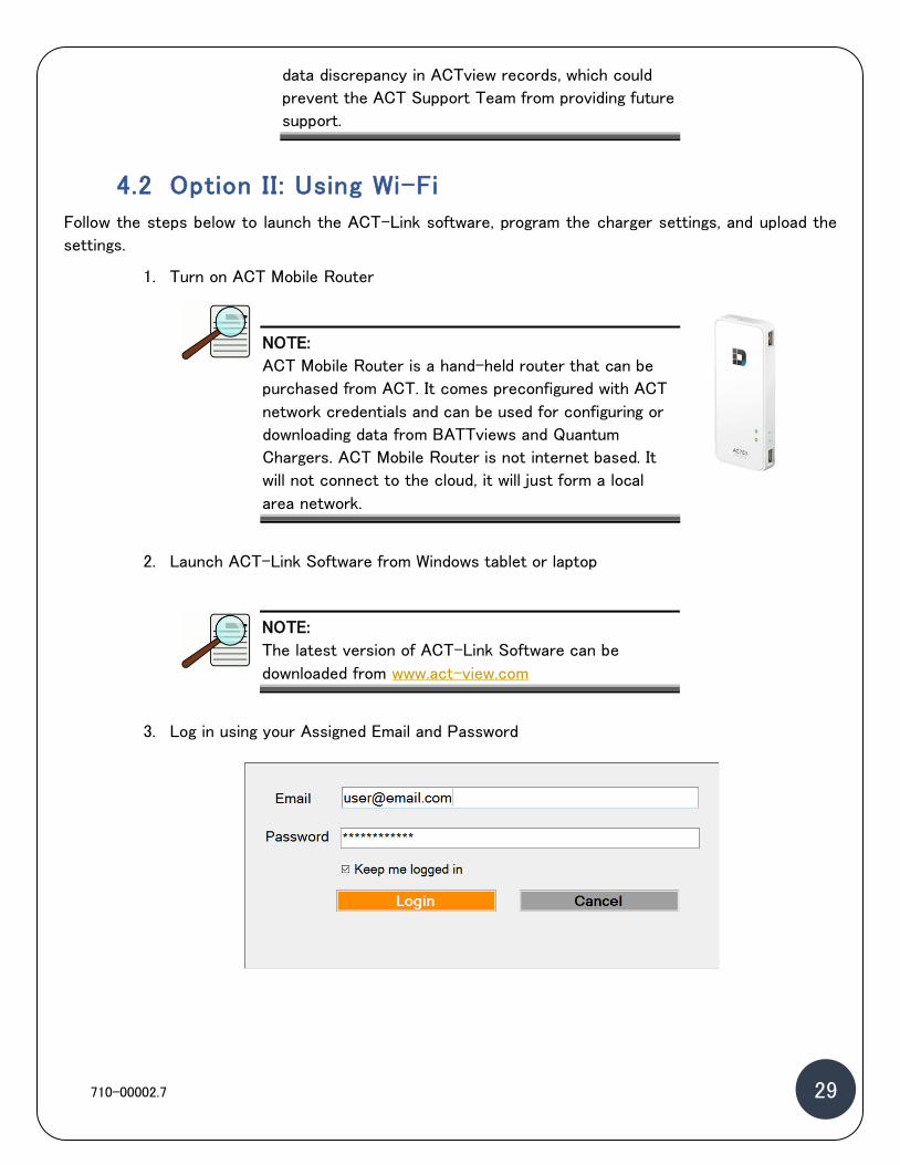
1. Turn on ACT Mobile Router
NOTE:
ACT Mobile Router is a hand-held router that can be
purchased from ACT. It comes preconfigured with ACT
network credentials and can be used for configuring or
downloading data from BATTviews and Quantum
Chargers. ACT Mobile Router is not internet based. It
will not connect to the cloud, it will just form a local
area network.
2. Launch ACT-Link Software from Windows tablet or laptop
NOTE:
The latest version of ACT-Link Software can be
downloaded from www.act-view.com
3. Log in using your Assigned Email and Password

710-00002.7 30 30
NOTE:
Users can obtain ACTview User Name and Password by
registering at www.act-view.com
4. Choose Mobile Router Mode from list of connectivity options
5. Follow the same step from Option I above starting at Step 5 Section 4.1

710-00002.7 31 31
Chapter 5: OPERATION
Users operate the Quantum charger through the front LCD touch screen. The LCD screen is the main
user interface for viewing and displaying operation and fault messages. It also allows limited charger
programming options.
5.1 Powering the Charger
1. Energize the AC mains (turn the main AC disconnect switch to the ON position if one
exists).
2. Verify that the LCD display is lit and Quantum logo is displayed indicating that the unit is in
Start Up Mode.
3. After Start Up, the charger will display the following screen as shown below.

710-00002.7 32 32
NOTE:
If the LCD is not lit, or if the message is not displayed,
cycle the Main AC disconnect switch to the OFF
position and then to the ON position to restart the
charger.
If the charger still does not power up, carefully verify
the source circuit and wiring to the charger and
correct any problems. Check that the fuses in the AC
mains junction box on the wall are intact and check
the supply voltage for all three phases (AC mains line-
to-line) to ensure it is within ± 10%, and matches to
10 VAC or better.
If the problem persists, contact the Dealer or ACT
Service.
5.2 Starting a Charge Cycle
1. Connect the battery to the charger. Once the battery is detected, the charger Auto Start count
down will appear on the screen.
NOTE:
If the charger is setup to communicate with battery
BMS (most Li-Ion Batteries), the following screen will
be displayed instead of the count down.

710-00002.7 33 33
If the charger doesn’t detect the BMS on the battery the following screen will be displayed after
45 seconds.
If the following screen appears, it indicates an error on the communication board, restart the
charger to clear the error.
Waiting For BMS…

710-00002.7 34 34
NOTE:
If the problem persists, contact the Dealer or ACT
Service. If the charger is not set to start automatically,
start the charge cycle by pushing the Green START
button on the screen.
NOTE:
All Outdoor/GSE chargers have to be set for auto start
since the touch screen is disabled.
Quantum Charger LCD Screen Outdoor/ GSE LCD Screen
If either this screen or this message is not displayed, the battery has not been detected. Make
sure that the battery cables are connected properly and verify that the auxiliary contacts are
properly connected.
2. The Charge Cycle begins and the following screen showing the Charging Status display appears.

710-00002.7 35 35
3. If the charger is set up for Li-Ion batteries the following screen will appear instead.
4. The Charging State indicates the active charging mode (TR for trickle, CC for constant current,
CV for constant voltage, FI for finish, or EQ for equalize). The screen also displays the Charging
Timer, % State of Charge gauge along with actual readings of Charging Amps (A), Charging Amp-
hours (AH), Battery Voltage (V), and Battery Temperature (T).
Charge
Current
Charging
timer
Battery
Temperature
Charging
kWhr
Charging
State
Charge
AH
Battery
Voltage
Battery SOC T ime & Date Charger ID
Home
button
Battery
Charge
indicator
Wi- Fi
Connectivity

710-00002.7 36 36
5. To stop the Charge Cycle, select the STOP button. The options to RESUME or EXIT will appear
on the screen.
6. Selecting EXIT stops the charger completely and defaults to the START screen. Selecting RESUME
from the screen resumes the Charge Cycle and the screen will again display the charging operation
display.
7. Once the Charge Cycle has completed, the charger will display “Completed” on the screen.

710-00002.7 37 37
5.3 Charger LED Color Indication
The LED strip attached under the charger front bezel, has a color indication to allow the user to identify
the Charging Cycle and identify any issue with the charger.
710-00002.7 38 38
Chapter 6: QUANTUM CHARGER PREVENTIVE
MAINTENANCE
The Quantum charger streamlined design emphasizes ease of maintenance. Preventative Maintenance is
mandatory annually to maintain warranty – twice a year is recommended.
The maintenance Below is the list of the maintenance procedures:
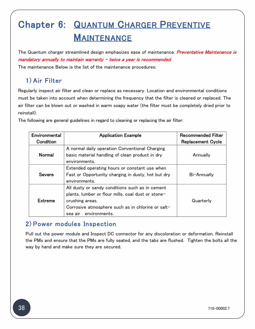
1) Air Filter
Regularly inspect air filter and clean or replace as necessary. Location and environmental conditions
must be taken into account when determining the frequency that the filter is cleaned or replaced. The
air filter can be blown out or washed in warm soapy water (the filter must be completely dried prior to
reinstall).
The following are general guidelines in regard to cleaning or replacing the air filter:
Environmental
Condition
Application Example Recommended Filter
Replacement Cycle
Normal
A normal daily operation Conventional Charging
basic material handling of clean product in dry
environments.
Annually
Severe
Extended operating hours or constant use when
Fast or Opportunity charging in dusty, hot but dry
environments.
Bi-Annually
Extreme
All dusty or sandy conditions such as in cement
plants, lumber or flour mills, coal dust or stone-
crushing areas.
Corrosive atmosphere such as in chlorine or salt-
sea air environments.
Quarterly
2) Power modules Inspection
Pull out the power module and Inspect DC connector for any discoloration or deformation. Reinstall
the PMs and ensure that the PMs are fully seated, and the tabs are flushed. Tighten the bolts all the
way by hand and make sure they are secured.

710-00002.7 39 39
3) DC Backplane Inspection
Remove the charger back cover and inspect the DC backplane for any discoloration. Report any
discoloration to
Clean DC connector contacts Slight discoloration of DC connector contacts
4) Battery Cables Inspection
Regularly inspect the DC cables for wear. If the DC cables or connectors become worn or damaged, they
should be immediately replaced with a cable of the same rating by qualified personnel. Inspect the
connector housing and make sure there is no damage. Inspect the tips of the battery connector for signs of
pitting due to arcing. Replace the tips as needed. Check the torque lines inside the charger. If needed, make
sure the torque is around 21 Ft-Lbs. (+0 /- 10%)
IMPORTANT NOTE: Please Refer to doc 710-00037 Quantum GSE Maintenance
Manual for more instructions on the Maintenance of the GSE
chargers

710-00002.7 40 40
Chapter 7: TECHNICAL SPECIFICATIONS
7.1 Nameplate Rating
The Nameplate Rating Label is attached to the side of the charger; an example is shown below:
The label specifies the Input Voltage and Current Rating for the charger, as well as the Output Rating. It
also contains the UL Listing and File Number.
7.2 Charger Operating Conditions

710-00002.7 41 41
The charger operating conditions are listed in the table below, please ensure that the site operation
conditions match the charger operation limits before installing the charger.
Operating Conditions
Ambient Temperature
0–50oC
Humidity 10–90% RH noncondensing
Cooling Forced air (fans)

710-00002.7 42 42
APPENDIX A: FLOOR MOUNTING PATTERN
Quantum Q4 Charger

710-00002.7 43 43
Quantum Q6 Charger

710-00002.7 44 44
Quantum Q12 Charger

710-00002.7 45 45
Outdoor/GSE Q6 Charger

710-00002.7 46 46
Outdoor/GSE Q12 Charger
26.000 1.350 1.640
AC INLET
38
.70
0
25.000
6.650
11
.10
0
1.344
20
.00
0
22.500
4X 0.484 21.000
1.5
00
2.5
00
22
.00
0
FOOTPRINT - LOOKING DOWN
NOTES: 1 - ADDITIONAL CLEARANCE REQUIRED AT SIDES FOR CABLES AND BEHIND UNIT FOR PROPER AIRFLOW. REFER TO INSTALLATION MANUAL FOR DETAILS.
REVISIONS
REV. ECN DESCRIPTION DATE
00 - INITIAL DESIGN 01/14/19
01 - UPDATED FOR CHASSIS LENGTH INCREASE 02/04/19
02 - UPDATED FOR MINOR CHASSIS UPDATES 02/26/19
D
C
B
AA
B
C
D
12345678
8 7 6 5 4 3 2 1
THE INFORMATION CONTAINED IN THIS
DRAWING IS THE SOLE PROPERTY OF
ADVANCED CHARGING TECHNOLOGIES,
INC. ANY REPRODUCTION WHETHER
WHOLE OR IN PART WITHOUT EXPRESS
WRITTEN PERMISSION IS PROHIBITED.
PROPRIETARY AND CONFIDENTIAL
NEXT ASSY:
DIMENSIONS ARE IN INCHES
TOLERANCES:
BEND : 90 1.0 : <>90 2.0
.010" HOLE (NON-PEM)
.010" HOLE/EDGE TO HOLE/EDGE
.015" HOLE/EDGE/BEND TO BEND
.025" CORNER FILLETS, BEND R
INTERPRET GEOMETRIC TOLERANCES
PER: ASME Y14.5-2009
MATERIAL:
FINISH:
DRAWN
CHECKED
ENG APPR.
DATENAME © Advanced Charging Technologies, Inc.Orlando, FL USA
TITLE:
SIZE
BDWG. NO. REV.
WEIGHT: SCALE: 1:10
UNLESS OTHERWISE SPECIFIED:
02
J. HOLMAN
J. HOLMAN
K. RUSTOM 02/26/19
02/26/19
02/26/19
QS-O 12X GSE OUTDOOR CHARGER ASM,
OVERALL DIMENSIONS
SHEET 1 OF 1
DWG-00300 QS-O 12X ASM R02
DO NOT SCALE DWG.
-
-
860-00052

710-00002.7 47 47
APPENDIX B: FLOOR STAND MOUNTING PATTERN
Quantum Charger Floor Stand Mounting Pattern
Quantum GSE Charger Floor Stand Mounting Pattern

710-00002.7 48 48
APPENDIX C: WALL MOUNTING PATTERN
Quantum Q4 Wall Mount

710-00002.7 49 49
Quantum Q6 & Q12 Wall Mount