Quantitative analysis of SysML models - uni-konstanz.de€¦ · · 2016-03-30University of...
53
University of Konstanz Department of Computer and Information Science Bachelor Thesis for the degree Bachelor of Science (B. Sc.) in Information Engineering Quantitative Safety Analysis of SysML Models by Dominic Lehle (Matr.-Nr. 01 / 678352) 1 st Referee: Prof. Dr. Stefan Leue 2 nd Referee: Prof. Dr. Oliver Deussen Konstanz, 12. November 2011
Transcript of Quantitative analysis of SysML models - uni-konstanz.de€¦ · · 2016-03-30University of...

University of KonstanzDepartment of Computer and Information Science
Bachelor Thesis for the degreeBachelor of Science (B. Sc.) in Information Engineering
Quantitative Safety Analysis ofSysML Models
byDominic Lehle
(Matr.-Nr. 01 / 678352)
1st Referee: Prof. Dr. Stefan Leue2nd Referee: Prof. Dr. Oliver DeussenKonstanz, 12. November 2011


Abstract
Throughout the implementation of safety-critical systems the decision whichrequirements should be prioritized have to be balanced. It has been oftenignored that many failures of a system could have been addressed in earlydesign processes. Despite the lack of well-engineered methods for safetyanalysis, the costs and complexity often even keep industry giants awayfrom the safety analysis in early stages of the development. Another criteriais that immersed knowledge is required and not often found in industrialmethods. In QuantUM, a successful approach of Florian Leitner-Fischer tobridge this gap and improve the integration of quantitative safety analysismethods into the development process, all inputs needed for this type ofanalysis can be specified at the level of an UML model. However the gap stillexists for models which are not principally software-systems. The SysMLis a language based on UML and is an established standard in modelingcomplex and embedded systems in the industry today. Due to the fact thatUML includes, in the manner of speaking, the basic principles for SysML,it is convenient to apply and adjust an existent approach in order to bridgethe gap in systems engineering.
As a result we propose a profile for SysML to enable the specification ofall inputs needed for quantitative safety analysis in the early developmentprocess, and extend the functionality of the existent software on the level ofSysML.

Contents
Abstract 2
1 Introduction 51.1 Contributions . . . . . . . . . . . . . . . . . . . . . . . . . . . 71.2 Structure of the thesis . . . . . . . . . . . . . . . . . . . . . . 7
2 Foundations 82.1 Unified Modeling Language . . . . . . . . . . . . . . . . . . . 82.2 Systems Modeling Language . . . . . . . . . . . . . . . . . . . 92.3 Probabilistic Model Checking . . . . . . . . . . . . . . . . . . 102.4 The QuantUM Approach . . . . . . . . . . . . . . . . . . . . 12
3 The QuantSyM Approach 133.1 Motivation . . . . . . . . . . . . . . . . . . . . . . . . . . . . 133.2 Main differences between UML and SysML . . . . . . . . . . 143.3 Extension of SysML . . . . . . . . . . . . . . . . . . . . . . . 173.4 SysML-Profile for Quantitative Analysis . . . . . . . . . . . . 183.5 Stereotypes and example . . . . . . . . . . . . . . . . . . . . . 19
3.5.1 QSyMComponent . . . . . . . . . . . . . . . . . . . . 193.5.2 QSyMAttributeRange . . . . . . . . . . . . . . . . . . 213.5.3 QSyMTransitions
213.5.4 QSyMNormalOperation and QSyMFailurePattern . . 223.5.5 Failure patterns and state configurations . . . . . . . . 263.5.6 Requirements . . . . . . . . . . . . . . . . . . . . . . 293.5.7 Failure Propagation . . . . . . . . . . . . . . . . . . . 293.5.8 Repair and Spare Management . . . . . . . . . . . . . 31
3.6 Discussion . . . . . . . . . . . . . . . . . . . . . . . . . . . . . 34
4 From Quantitative SysML to PRISM 35
5 The resulting QuantSyM Tool 37
6 Case Studies 386.1 Airbag Control Unit . . . . . . . . . . . . . . . . . . . . . . . 38
7 Related Work 467.1 Probabilistic Model Checking of SysML
Activity Diagrams . . . . . . . . . . . . . . . . . . . . . . . . 46
2

8 Conclusion 478.1 Conclusion . . . . . . . . . . . . . . . . . . . . . . . . . . . . 478.2 Future Work . . . . . . . . . . . . . . . . . . . . . . . . . . . 47
9 Appendix 489.1 CD . . . . . . . . . . . . . . . . . . . . . . . . . . . . . . . . . 48
3

List of Figures
2.1 screenshot of the PRISM graphical user interface . . . . . . . 113.1 Dependencies between UML 2.0 and SysML . . . . . . . . . 143.2 SysML Diagram Taxonomy . . . . . . . . . . . . . . . . . . . 163.3 Dependencies of the QuantSyM Profile . . . . . . . . . . . . 173.4 Definition of the QSyMComponent stereotype . . . . . . . . . 193.5 Block diagram of the Railway Crossing System . . . . . . . . 203.6 Definition of the QSyMAttributeRange stereotype . . . . . . 213.7 Definition of the stereotypes for abstract and concrete stochas-
tic transitions. . . . . . . . . . . . . . . . . . . . . . . . . . . 223.8 State machine representing the normal operation for the Train 233.9 State machine representing the normal operation for the Car 243.10 State machine representing the normal operation for the Gate 253.11 State machine representing the normal operation for the Stop-
Light . . . . . . . . . . . . . . . . . . . . . . . . . . . . . . . . 253.12 State machine representing the ”Stuck” failure pattern for the
Gate . . . . . . . . . . . . . . . . . . . . . . . . . . . . . . . . 263.13 State machine representing the ”Stuck” failure pattern for the
Light . . . . . . . . . . . . . . . . . . . . . . . . . . . . . . . . 273.14 State machine representing the ”Broken” failure pattern for
the Gate . . . . . . . . . . . . . . . . . . . . . . . . . . . . . . 283.15 State machine representing the ”Stuck” failure pattern for the
Light . . . . . . . . . . . . . . . . . . . . . . . . . . . . . . . . 283.16 The QSyMFailureFlowRule stereotype derived from QuantUM 293.17 Example of a failure propagation . . . . . . . . . . . . . . . . 303.18 Definition of the stereotypes used for repair and spare man-
agement in SysML. . . . . . . . . . . . . . . . . . . . . . . . . 313.19 Internal block diagram example with a QSyMSpare. . . . . . 323.20 Railway Crossing block diagram illustrating the RepairUnit
mechanism. . . . . . . . . . . . . . . . . . . . . . . . . . . . . 335.1 QuantUM / QuantSyM GUI . . . . . . . . . . . . . . . . . . 376.1 Airbag Control Unit in SysML . . . . . . . . . . . . . . . . . 396.2 MicroController normal behaviour state machine . . . . . . . 406.3 MicroController failure pattern state machine . . . . . . . . . 416.4 State configuration attributes . . . . . . . . . . . . . . . . . . 416.5 FASIC failure pattern state machine . . . . . . . . . . . . . . 426.6 FASIC normal behaviour state machine . . . . . . . . . . . . 426.7 FET normal behaviour state machine . . . . . . . . . . . . . 436.8 FET failure pattern state machine . . . . . . . . . . . . . . . 44
4

Introduction
1 Introduction
In a recent joint work with an industrial partner the authors of [1] haveproven that probabilistic verification techniques can be applied to safetyanalysis in an industrial setting [1]. The approach they implemented hadproblems with the missing connection of their analysis to common existinghigh-level architecture models and the modeling languages that they aretypically written in. One of the common used languages that supports ana-lyzing, specifying, designing, verification and validation for system modelingis the Unified Modeling Language (UML) [2]. During their analysis approachthey had to use the language provided by the analysis tool they used, in thiscase the input language of the stochastic model checker PRISM [5] .TheTranslation from UML to the formal modeling language was a manual andthus a time-consuming procedure hence a way to ”bridge the gap betweenarchitectural design and formal stochastic modeling languages” had to befound.
In Order to bridge this gap Florian Leitner-Fischer [10] provides withinthe scope of his master thesis ”Quantitative Safety Analysis of UML Models”an extension of the Unified Modeling Language that offers possibilities tocapture probabilistic and error behavior information that are relevant for aformal stochastic analysis. Additionally he provides a translation processfrom UML models to the PRISM [5] language and developed a tool to fullyautomate this process. However if we look at the complete life-cycle of asystem, especially in regards to systems that do not only consist of software,the design language UML has some major gaps in respect to the modelingof systems:
1. UML serves to describe ”software-heavy” systems
2. UML does not address the relations between the requirements e.g.there is no possibility to trace a systems specifications down to designelements and test cases.
3. UML does not allow to allocate parts of the systems onto each other.Hence there is no possibility to associate a piece of software to thehardware deploying it.
4. UML models do not provide possibilities to model continuous physicalcircumstances
For this gaps between UML and Systems Engineering[17] and other reasonsthe SysML Partners, a group of software tool vendors and industry leaders
5

Introduction
created and developed a profile of UML for systems engineering called Sys-tems Modeling Language SysML[7]. The SysML is based on UML 2.0 andextends the language to specify systems containing hardware, software, data,personnel, assets and procedures. It reduces the UML to its system relevantdiagrams and stereotypes and leaves out the more software-specific. Overallit provides mechanisms to address the gaps in regard to system modelingAs a result, SysML is gaining broader recognition and acceptance acrossdifferent industries.
The objective of this thesis is to assign and extend the QuantUM Profileon SysML in order to fill the gap between architectural design and formalstochastic modeling languages in complex system environments. We takethe extension of Florian Leitner Fischer’s QuantUM and try to apply it tothe SysML Profile to capture probabilistic and error behavior informationthat are relevant for a formal stochastic analysis. Based on the existing ex-tension we evaluate the profile on different system models and add additionalpossibilities to annotate the SysML models with quantitative information.
6

Introduction
Contributions
1.1 Contributions
The main contributions of this thesis can be summarized as follows:
1. In regard to the differences between UML and SysML we evaluate howthe existing QuantUM approach for UML can be adapted to SysMLmodels, in order to enable quantitative safety analysis for SysML mod-els.
2. We extend the already existing profile to certain new elements in orderto provide the possibilities to annotate structural, behavioral diagramsand requirement diagrams with quantitative information. We namethe resulting notation QSyM.
3. We describe the development of a prototypical tool chain for quanti-tative system analysis.
4. We evaluate our SysML extension based on an industrial case study.
1.2 Structure of the thesis
In this thesis we analyze the portability from QuantUM to SysML and pro-vide an extension for SysML to enable quantitative system analysis to SysMLmodels.
In Chapter 2 we provide a short introduction to the Unified Model-ing Language, SysML, probabilistic model checking and the QuantUM ap-proach. In Chapter 3 the differences between the two modeling standardsUML and SysML are described in order to analyze the applicability of Quan-tUM to SysML, furthermore the quantitative extension of SysML is pre-sented. In Chapter 4 the changes for the translation rules from SysMl toPRISM are described. Subsequently what has been maintained from theQuantUM approach tool chain is shown in Chapter 5. That followed, theresulting profile extension is demonstrated and evaluated on a case studyin Chapter 6. Finally, related work is discussed in Chapter 7 followed bypossible future work and conclusions in Chapter 8.
7

Foundations
2 Foundations
2.1 Unified Modeling Language
The Unified Modeling Language (UML)[2] is a specification for visualizingand documenting models in the field of software and system engineering.The Object Management Group (OMG)[3] established UML as a standardfor the design of software applications and manages the structure of thelanguage. UML provides a large number of graphical elements, in orderto design visual models of software-intensive systems. The current releasedversion of UML is 2.4 -Beta 2 released in March 2011 [3] and it containstwo categories of diagrams. The category structural information includesseven diagram types representing information about the systems structure.The category behavioral information contains another seven diagrams rep-resenting the behaviour of certain objects in the system or their generalcommunication, with four of them including interaction aspects. The over-all overview of all language elements can be seen in the current UML Stan-dard Specification[4]. Although the OMG is a non-profit computer industryconsortium since 1989 they work continuously on improvements to the lan-guage.
So far, UML is the dominating standard for today’s system and softwarearchitecture modeling and a significant number of tools which support UMLexist. The most commonly used tools are IBM Rational Software Architect1,Sparxsystems Enterprise Architect2 and the open source tool ArgoUML3.The UML is standardized in ISO IEC 19501 Version 2.1.2. Additionallyother standards for the development of safety-critical systems like ISO IEC61508 [8] or ISO CD 26262 [9] highly recommend the usage of UML tospecify the design of software systems.
1http://www.ibm.com/software/rational/2http://www.sparxsystems.com/3http://argouml.tigris.org/
8

Foundations
Systems Modeling Language
2.2 Systems Modeling Language
The Systems Modeling Language SysML is an UML extension in order tobridge the gaps between the domain-specific usage of UML for Systems En-gineering. It is the result of a joint initiative of OMG and the InternationalCouncil on Systems Engineering (INCOSE) and built to verify and validatecomplex systems which are not necessarily built in a software-domain. TheSysML is based on UML 2.0 and extends the language to specify systemscontaining hardware, software, data, personnel, assets and procedures. Itreduces the UML to its system relevant diagrams and stereotypes and leavesout the more software-specific. Overall it provides the following importantmechanisms to address the gaps in regard to system modeling:
1. A possibility to define requirements modeling in a more complex way.
2. Extensions to system structure modeling by defining additional stereo-types like blocks and value properties.
3. The possibility to define parametric models.
4. Allocations that allow to establish relations between different sub-systems or levels of the system e.g. structure and behavior, logicaland physical...
5. Extensions to enable modeling of time-continues activities and objectflows
Today SysML is used by more than just system engineers on complex sys-tems and a large desire to continue using SysML in organizations exists[14].
In order to apply the QuantUM approach to SysML we will go into morespecific differences between the UML and the SysML in [3.2].
9

Foundations
Probabilistic Model Checking
2.3 Probabilistic Model Checking
Complex systems consume more time and effort on verification than onconstruction. Probabilistic Model Checking[11] is an automated verificationmethod, which is used to analyze safety-critical systems.
Like in general Model Checking , two inputs are required: a model ofthe system to be analyzed and a specification of the quantitative propertiesof the system that are to be analyzed.
In Probabilistic Model Checking the Model Checker constructs a prob-abilistic model out of the system model. The result is a probabilistic state-transition system, with states representing a possible configuration of thesystem and transitions that represent a possible evolution of the systemfrom one configuration to another over time. In Probabilistic Model Check-ing the transitions are additionally labeled with quantitative informationwhich specifies the probability and/or timing of the transition’s occurrence.In Leitner-Fischer’s QuantUM approach he uses continuous-time Markovchains CTMC [11] which is one of several methods to check a model. The
Figure 2.1: Probabilistic Model Checking
state-transition system is extended to probabilities in that case discreteprobability distributions are assigned to the transitions. The CTMC alsoassumes that no deadlock state exists, therefore every state has at least oneoutgoing transition. The probabilistic model checker explores the model andconstructs all possible occurent paths, for a formal specification given. Thespecification for the Probabilistic Model Checker is declared using a vari-ant of temporal logic. The temporal logic used in this thesis as well as inLeitner-Fischer’s QuantUM approach to describe the Markov chains is theContinuous Stochastic Logic (CSL) [12, 13]. [13]. CSL enables to specify theprobability of a state, in order to satisfy some temporal property includingthe time interval in which this property must hold. It is an extension ofthe Computation Tree Logic (CTL) [14] and adds a probabilistic operatorin order to refer to the probability of the occurrence of particular paths in
10

Foundations
Probabilistic Model Checking
the CTMC. A steady state operator is added as well in order to refer to theprobability residing in a particular set of states specified by a state formulaat long sight. The state and path formulas are based on [15]. The stateformulas are interpreted over states of a CTMC, whereas the path formulasare interpreted over paths in a CTMC. The steady-state operator refers tothe probability in which it converges in. The time span of a certain path,is expressed by the path operators until (U) and next (X), extended with aparameter that specifies a time interval.
There are two possible ways for approximating probability measure: nu-merical and statistical. Probabilistic model checking uses numerical methodsfor the approximations in form of a truncation error, hence it is better to ob-tain more accurate and exact results compared to discrete-event simulationtechniques, which samples model’s executions and produces an estimationof the measure of interest.
In this thesis we use PRISM [5, 6], a probabilistic model checker de-veloped at the University of Oxford. It accepts probabilistic models likeCTMCs in its simple high-level state-based modeling language.
Figure 2.2: screenshot of the PRISM graphical user interface
PRISM has also been used in Florian Leitner-Fischer’s QuantUM ap-proach, which served as a foundation for this thesis.
11

Foundations
The QuantUM Approach
2.4 The QuantUM Approach
The QuantUM approach [QuantUM] is Leitner-Fischer’s approach to ex-tend the UML with a profile for quantitative analysis, where all inputs ofthe quantitative system analysis are specified in UML. He extended the stan-dard UML so that all information that is needed to perform a quantitativeanalysis, in that case probabilistic model checking, can be specified at thelevel of UML. In order to extend UML he added structural description capa-bilities to the language so it is possible to present dependencies of differentcomponents, e.g. that a failure of a specific component influences a failure ofanother component. The behavioral description is extended too, to providea possibility to include stochastic behavior in the model. A model anno-tated with the QuantUM extension, allows to specify all information neededto perform the safety analysis. Additionally a tool is provided to parse theanalysis model and translate it into the input language of the probabilisticmodel checker PRISM. With the resulting PRISM model counterexamplesfor the probabilistic properties are computed throughout the PRISM exten-sion DiPro. The results are then represented as a fault tree which can bemapped onto UML sequence diagrams.
In this thesis we will extend the existing QuantUM UML profile so itallows the application to the SysML.
12
The QuantSyM Approach
3 The QuantSyM Approach
3.1 Motivation
The QuantUM approach already specifies all information needed for a quan-titative analysis of UML models. Additionally the QuantUM Tool automat-ically translates the corresponding annotated model in the analysis modeland represents the results in a sequence diagram. Since SysML is basedon several elements of UML it is suitable to use the existing approach andadjust it to several other needs for the system engineering domain.
In order to do so, we define our requirements of the extension for SysMLon the same requirements that were crucial for the acceptance of the Quan-tUM approach:
1. Applicability is provided on system and software architectures definedin SysML.
2. It is possible to specify dependability objectives / requirements.
3. Means for the specification of dependability characteristics of the sys-tem components, such as failure modes and rates are existent
4. Means to specify failure propagation paths and dependencies betweendifferent system components are existent
5. There are possibilities to model safety mechanisms such as redundancystructures and repair management.
6. Experienced users (i.e. system engineers) are easily able to acquire theknowledge about how to use the extension
7. The additional modeling with QuantSyM shall be as inexpensive aspossible
13

The QuantSyM Approach
Main differences between UML and SysML
3.2 Main differences between UML and SysML
SysML is built on UML 2.0 and satisfies the needs of system engineers byadapting UML when it is necessary. Therefore SysML removes the software-
Figure 3.1: Dependencies between UML 2.0 and SysML
specific diagrams and focuses more on system relevant’s. Thus UML issplit in the UML concepts necessary for SysML and the ones not. Thedependencies between both modeling standards is shown in Figure 3.1.
The four diagram types: use-case diagram, state machine diagram, pack-age diagram and sequence diagram haven’t changed in SysML and thereforeact the same as they did in UML. The package diagram describes the sys-tem and the projects structure, the use-case diagram allows to describe thesystems function from a user perspective, the sequence diagram allows forexample to model the course of events or interactions between system partsand finally the state machine diagram, which enables to model the dynamicbehaviour of the system or its parts. Some diagrams from UML are alreadyuseful but need to be modified to fit into the systems engineering environ-
14

The QuantSyM Approach
Main differences between UML and SysML
ment. The class diagram for instance is simplified: All the software specificelements have been removed, furthermore classes are now blocks and builda unifying basis element for systems. Another diagram modified from UML2 is the internal block diagram, which specifies the interconnection of parts.Like its UML 2 predecessor, the composite structure diagram, the internalblock diagram specifies the interconnection of parts. Additionally to thenormal ports, flowPorts are introduced in SysML which enable the mod-eling of physical or continuous flows. The direction of flowPorts plays animportant role and is indicated by an arrow. The activity diagram is thelast diagram taken from UML 2 and modified to the needs of system engi-neering. In SysML’s activity diagrams still specify the controlled sequenceof actions, the main addition is the possibility to control the execution ofactions, for instance running actions can be disabled. The limited control ofactions in UML 2 is extended by control operators making it possible thata behaviour may not terminate by itself, but instead externally.
When representing requirements, system engineers early met their limitsof UML. Although the current version of UML provides many possibilities tospecify requirements for a system, it is not possible to trace requirements ofa system from informal specifications to specific design elements. Use casesfor example help build up a base for understanding the expected behaviorof a system and can validate its architecture, but requirements often onlytrace to the use cases but not to the other parts of the system. The addi-tion of information which captures reasons for specific design decisions,madeduring the development process and linking them to the requirements helpsto analyze consequences that appear if a requirement changes. Additionallyto the traceability limitation, no model element provides the possibility todeclare non-functional requirements. With the requirement diagram SysMLintroduces a tool to define several kinds of relationships for improving therequirement traceability. Requirements can now be linked to the design andto the test suite and can be build up in a similar way than class diagrams.
SysML also introduces the concept of assembly, a stereotyped class whichdescribes a system as a structure of interconnected parts. An assembly pro-vides a domain neutral modeling element that can be used to represent thestructure of any kind of system, regardless of the nature of its components.The concept of allocation in SysML is a more abstract form of deploymentthan in UML. It is defined as a design time relationship between modelelements which maps a source into a target. An allocation provides the gen-eralized capability to allocate one model element to another. For example,it can be used to link requirements and design elements, to map a behaviorinto the structure implementing it, or to associate a piece of software and
15

The QuantSyM Approach
Main differences between UML and SysML
Figure 3.2: SysML Diagram Taxonomy
the hardware deploying it. The SysML support for flows between assembliesis meant to provide an equivalent and domain-neutral modeling capability.In particular the control of execution is extended such that running actionscan be disabled.
Finally the focus on system engineering leads to the removal of puresoftware specific diagrams. Therefore the communication diagram, interac-tion diagram and timing diagram are not used in SysML. An overview ofthe SysML diagram taxonomy in regards to the important diagrams used inQuantUM can be seen in figure 3.3.
16

The QuantSyM Approach
Extension of SysML
3.3 Extension of SysML
SysML as well as UML includes built-in mechanisms: model libraries andprofiles to customize the language. In general a modeling language contains anumber of distinct language concepts, which are represented by a collectionof metaclasses. Metaclasses define the behavior of certain elements andinstances and include a set of properties and constraints to do so. Thecollection is called metamodel and the underlying metamodel for SysML isUML for SysML (UML4SysML) [figure 3.1].
A profile is some kind of package for specific domains and platforms. Itserves as the container for a set of stereotypes and supporting definitions.A stereotype [4] is an extensibility mechanism providing the possibility toadd certain properties to an already existing metaclass. Typically a profilecontains a set of stereotypes representing a contiguous set of concepts for aspecific modeling domain. QuantUM defines concepts that add further infor-mation to the UML model in order to perform a quantitative analysis safetyof UML Models. Any UML model element can be extended by Leitner-Fischer’s defined stereotypes. In SysML several elements used in QuantUMare not existent because SysML references the UML4SysML metamodel toextend its metaclasses, therefore we have to change and extend the profilein order to keep the compliance of SysML.
Figure 3.3: Dependencies of the QuantSyM Profile
17

The QuantSyM Approach
SysML-Profile for Quantitative Analysis
3.4 SysML-Profile for Quantitative Analysis
In this subsection we will describe the SysML profile for quantitative ana-lysis in regard to changes we made to QuantUM. We will briefly explainthe stereotypes introduced by Leitner-Fischer and additional stereotypes weadded in order to add required information to SysML. In accordance withUML, SysML splits the model into two fundamental parts: the structuraland the behavior part. Static elements and the architecture or structure ofthe system are described in the structural part, dynamic behavior betweenelements and parts and their associated relationships however are describedin the behavior part of SysML. In addition SysML introduces new cross-cutting constructs: allocations and requirements[18]. Whereas the last oneprovides possibilities to attach problems and rationales to any model ele-ment in order to capture issues and decisions. Therefore we could use itto directly trace the requirements onto blocks or other parts of the system.The capture of the dependency of a model’s structure, is described in UMLas well as in SysML, in the structural part of the model. Hence we canassign the extension of the structural description capabilities of QuantUMto SysML in regards to specific changes to elements throughout SysML. Thesame applies to the extension of the behavioral description to capture thestochastic behavior. In course of this thesis we use the prefix QSyM for thenames of stereotypes that belong to our SysML profile. Subsequently wedefine the new stereotypes, properties and their changes from the originalQuantUM profile as well as new stereotypes from scratch used to specifythe information needed to perform stochastic analysis. We demonstrate theusage of the profile on a railway crossing example: the model consists of atrain, a car, a gate, and a stop-light. Whenever a train is approaching thegate is requested to close and the stop-lights are requested to start flashingshowing the car that it has to stop. As soon as the train left the crossing,the gate is being signaled that it should be opened again and the stop-lightsshould stop flashing and the car can cross the gate.
18

The QuantSyM Approach
Stereotypes and example
3.5 Stereotypes and example
3.5.1 QSyMComponent
Figure 3.4: Definition of the QSyMComponent stereotype
The stereotype QSyMComponent is the SysML version of the QUM-Component in QuantUM. It can be assigned to all SysML elements thatrepresent building parts or blocks of the real system, therefore to the blockelement that replaces UML classes, and to packages and parts. The QSyM-Component does not differ from the basic structure of the QUMComponent,hence it comprises up to one (hierarchical) state machine representing thenormal behavior and one to finitely many (hierarchical) state machines thatrepresent the possible failure patterns. As already mentioned in previouschapters the state machine diagrams and their corresponding elements havebeen adopted from UML, therefore state machines can be treated the sameas in QuantUM. The QSyMComponent still includes the list of Rates con-taining the rates with the names identifying them. The final QSyMCompo-
19

The QuantSyM Approach
Stereotypes and example
nent stereotype, its dependencies and attributes is shown in Figure 3.4. The
Figure 3.5: Block diagram of the Railway Crossing System
block diagramm of our railway crossing system is shown in Figure 3.6. Inorder to analyse the behavior of all the blocks, all of them are tagged withthe stereotype QSyMComponent. The Gate block contains the operationswitchGate and a boolean attribute with the name closed represents thegate’s state. The Stop-Light block contains the boolean attribute flashingindicating whether or not the stop light is flashing. The dependency of theTrain block to the Gate block can be seen as continuous flow, as a train con-stantly crosses the gate. The same applies to the car, but it can only crossthe Gate when it is not closed. With the tagged stereotype QSyMCompo-nent we now allow the association with the state machines representing thenormal and failure behavior like in QuantUM.
20

The QuantSyM Approach
Stereotypes and example
3.5.2 QSyMAttributeRange
The QSyMAttributeRange keeps the same functionality as the QUMAt-tributeRange in QuantUM: It allows for the specification of the range ofinteger attributes of the QSyMComponents needed for finite state verifica-tion methods like probabilistic model checking.
Figure 3.6: Definition of the QSyMAttributeRange stereotype
3.5.3 QSyMTransitions
As in the UML the possibility to specify quantitative information like failurerates in SysML is not possible because state machine diagrams and thereforetransitions haven’t been changed. hence we apply the stereotypes used inQuantUM to the transition element in state machines . QSyMAbstractStoch-asticTransition and QSyMStochasticTransition extend the capability of tran-sitions (see Fig. 3.7) like their QuantUM predecessors and enable the userto specify rates as well as a name for it. These transition rates are usedfor the continuous-time Markov chains generated for the stochastic analysis.The stereotype QSyMAbstractStochasticTransition acts as a superclass forthe different specializations and it does not contain a default rate. Conse-quently there has to be a rate in the Rates list of our QSyMComponent, ifa state machine is connected to this QSyMComponent, in order to specify arate for this transition. This enables the individual specification of rates foreach component out of a repository. Basically we need the same two tran-sition types used in QuantUM. Thus we define the QSyMFailureTransitiondescribing a transition to a failure pattern and the QSyMRepairTransitionwhich describes the transitions back to a normal behaviour, explained lateron 3.5.8. The ”Abstract” Version of each of the transitions fulfills the priormentioned function: it does not contain a default rate.
21

The QuantSyM Approach
Stereotypes and example
Figure 3.7: Definition of the stereotypes for abstract and concrete stochastic transitions.
3.5.4 QSyMNormalOperation and QSyMFailurePattern
A QSyMComponent consists of one Normal Operation state machine, de-scribing the normal behaviour and one to infinitely Failure Pattern statemachines. In the Tool and hence not visible for the user, these state machinesare combined in exactly one hierarchical state machine. The functionality ofthis in QuantUM established manner of modeling works as followed: Firstof all the QSyMComponent executes the normal operation state machine.While executing this operation an error can occur. For instance if a QSyM-FailureTransition is enabled, the QSyMComponent enters the correspondingfailure pattern state machine with the specified rate.
In our Railway Crossing example we tagged all of the blocks with theQSyMComponent stereotype. The Train block and the Car act only asenvironment input, therefore they only have a normal behaviour. In orderto keep the complexity manageable we consider them as a sub-system, not
22

The QuantSyM Approach
Stereotypes and example
important for the correct behaviour of the gate and the stop-light. Thereforewe do not specify any failure patterns in these blocks. Our Train has threepossible states (Figure 3.8). In the driving state the train is not near thegate, hence the approaching variable is set to false. If he is approaching thegate the corresponding variable is set to true. This keeps until he is notcrossing the gate anymore .
Figure 3.8: State machine representing the normal operation for the Train
The state machine for the normal operation (Figure 3.9) of the Car showsthat the Car is initially driving. Whenever it is near the gate, it takes thetransition to Approaching. In this state the variable closed is the guard forthe next possible transition. The car can only cross the gate if the gate isopen, otherwise it has to stop.
Two blocks are more important for the behaviour of our system, namelythe Stop-Light block and the Gate Block. In our example we assume thatthe Gate is controlling the Stop-Light and that there is no additional Sensorblock that indicates that a train is approaching.
23
The QuantSyM Approach
Stereotypes and example
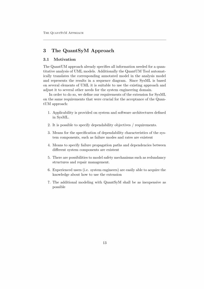
Figure 3.9: State machine representing the normal operation for the Car
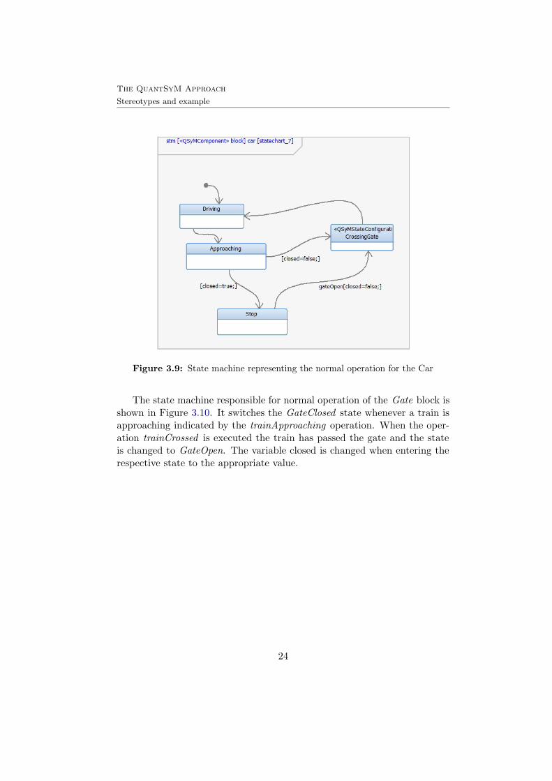
The state machine responsible for normal operation of the Gate block isshown in Figure 3.10. It switches the GateClosed state whenever a train isapproaching indicated by the trainApproaching operation. When the oper-ation trainCrossed is executed the train has passed the gate and the stateis changed to GateOpen. The variable closed is changed when entering therespective state to the appropriate value.
24
The QuantSyM Approach
Stereotypes and example
Figure 3.10: State machine representing the normal operation for the Gate
Figure 3.11: State machine representing the normal operation for the Stop-Light
25

The QuantSyM Approach
Stereotypes and example
Figure 3.12: State machine representing the ”Stuck” failure pattern for the Gate
3.5.5 Failure patterns and state configurations
In Figure 3.12 one of the two possible failure patterns of the Gate block isshown. The Stuck failure pattern can either go to the StuckOpen state wherethe gate keeps open or to the StuckClosed state where the gate keeps closed.The closed variable changes its value to false upon entry to the StuckOpenstate and true upon entry to the StuckClosed state. Additionally we assignthe QSyMStateConfiguration stereotype to the StuckOpen and StuckClosedstate in order to define one state configuration. A state configuration inQuantUM can be seen as a boolean formula: each state can either be true orfalse depending on whether the system is in this state or not. Additionallyan operator variable indicates how the boolean variables representing thestates are connected by each other. This operator can be either a logic or-operator (OR) or a logic and-operator (AND). In our running example wename these state configuration SystemStuck and select the or-operator toconnect them. Our defined state configuration SystemStuck is true wheneverthe system is in at least one of the ”Stuck” states.
26

The QuantSyM Approach
Stereotypes and example
Figure 3.13: State machine representing the ”Stuck” failure pattern for the Light
The state configuration is applied to the Stop-Light Stuck failure patternas well which allows us to determine the probability of reaching a ”Stuck”failure in the further progress of the analysis. QSyMStateConguration hav-ing the same name are treated as one. Another QSyMStateConfigurationwith the name SystemDown is applied to two other failure patterns, whereasone of each corresponds to a different block (i.e. Gate and Stop-Light). Fig-ure 3.14 shows the failure pattern GateBroken which consists of one failurestate where the Gate is Broken and the variable closed is set to false by theentry action, and a state tagged with the QSyMStateConfiguration namedSystemDown. The state machine describing the Stop-LightBroken failurepattern (Figure 3.15) consists of one failure state where the Stop-Light isbroken and the variable flashing is set to false by the entry action, thereforeit can’t flash whether or not the train is approaching. The SystemDownstate configuration is now true whenever the system is in one of the ”Bro-ken” states. Since we are interested in the analysis of unanticipated failures,that is the car is crossing and the train is crossing, we tagged the Crossing-Gate state in both, the normal behaviour state machine for the car and thetrain, with the state configuration named Crash (Figure 3.8 and 3.9)
27

The QuantSyM Approach
Stereotypes and example
Figure 3.14: State machine representing the ”Broken” failure pattern for the Gate
Figure 3.15: State machine representing the ”Stuck” failure pattern for the Light
28

The QuantSyM Approach
Stereotypes and example
3.5.6 Requirements
In SysML it is possible to trace requirements to every design element inthe model. Hence in our QuantSyM tool we add the possibility to checkall model elements for requirements. These requirements can then be usedas additional checks for all elements. For instance failure rates can thenbe specified by requirements. This enables to trace the design decisionsmade during the creation of development artifacts to the roots and helps toanalyze consequences in the process. In our example we add the requirement”StopLight failureRate<=0.8” (Figure 3.15). The tool then checks if thefailureRate for the StopLight is below that rate, if not it sets the rate to 0.8.This ensures that in the tool certain variables can be restricted to reasonablevalues.
Beside of that we also offer an additional possibility to automaticallycreate property specifications out of requirements: In QuantUM the Conti-nous Stochastic Logic (CSL) [?] [16] is used to specify the properties thatwant to be verified. These CSL properties are generated automatically outof the SysML model by the QuantSyM tool, and the state formulas vari-able for time (t) can be restricted to a certain value. In QuantSyM it is nowpossible if for instance the requirement ”P<x in t=2” is linked to a state con-figuration (stc), that the resulting CSL property: P<x[(true) U<=2 (stc))]is generated for that state configuration. In the railway example one re-quirement is added (see Figure 3.15) to the state configuration SystemDownwhich leads to the construction of the CSL property P<0.7[(true)U<=2 (Sys-temDown)] automatically by the tool .
3.5.7 Failure Propagation
The QuantUM approach offers two ways to specify a failure propagation,whereas specifying the behaviour by state machines is only one. In our rail-way crossing example a failure of the Gate block does not automaticallypropagate to the Stop-Light block. In our case the Train block is respon-sible for the indication of a train approaching . Whenever this indication
Figure 3.16: The QSyMFailureFlowRule stereotype derived from QuantUM
29
The QuantSyM Approach
Stereotypes and example
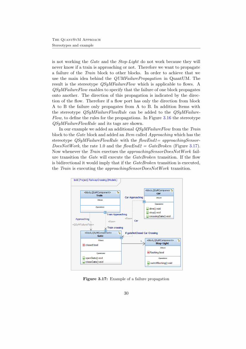
is not working the Gate and the Stop-Light do not work because they willnever know if a train is approaching or not. Therefore we want to propagatea failure of the Train block to other blocks. In order to achieve that weuse the main idea behind the QUMFailurePropagation in QuantUM. Theresult is the stereotype QSyMFailureFlow which is applicable to flows. AQSyMFailureFlow enables to specify that the failure of one block propagatesonto another. The direction of this propagation is indicated by the direc-tion of the flow. Therefore if a flow port has only the direction from blockA to B the failure only propagates from A to B. In addition Items withthe stereotype QSyMFailureFlowRule can be added to the QSyMFailure-Flow, to define the rules for the propagations. In Figure 3.16 the stereotypeQSyMFailureFlowRule and its tags are shown.
In our example we added an additional QSyMFailureFlow from the Trainblock to the Gate block and added an Item called Approaching which has thestereotype QSyMFailureFlowRule with the flowEnd1= approachingSensor-DoesNotWork, the rate 1.0 and the flowEnd2 = GateBroken (Figure 3.17).Now whenever the Train exectues the approachingSensorDoesNotWork fail-ure transition the Gate will execute the GateBroken transition. If the flowis bidirectional it would imply that if the GateBroken transition is executed,the Train is executing the approachingSensorDoesNotWork transition.
Figure 3.17: Example of a failure propagation
30

The QuantSyM Approach
Stereotypes and example
Figure 3.18: Definition of the stereotypes used for repair and spare management in SysML.
3.5.8 Repair and Spare Management
The QuantUM UML extension also includes possibilities to model repairmanagement strategies. These strategies are enabled throughout the defi-nition of repair units which replace or repair failed system components. Inorder to enable that modeling enhancement we apply the same functionalityto SysML. Hence the QSyMSpare component,derived from the QUMSparein QuantUM, is added to our SysML extension with slight changes. Thestereotype can be assigned to parts in the internal block diagram, and itsassociated part then functions as a spare. Therefore whenever the mainblock activates a failure, the QSyMSpare is activated with a rate which isspecified in its activationRate.
Supplementary to the QSyMSpare stereotype we also add the QSyM-RepairUnit derived from the QuantUM counterpart QUMRepairUnit withminor changes in order to be suitable to SysML. Applicable to blocks it canbe associated to other QSyMComponents by a flow or an association withthe QSyMRepairAssociation stereotype. The block tagged with this stereo-type has the functionality to repair the components having a connectionin form of an association or flow to it. The two different repair strategiesfrom QuantUM are adopted in the QSyMRepairStrategies and have to bespecified in the strategy tag in the QSyMRepairUnit. The dedicated strat-
31
The QuantSyM Approach
Stereotypes and example
egy repairs exactly one component per repair unit and the first come firstserve (FCFS) strategy can repair more than one component, processing thecomponents in the rule the name implies. The QSyMRepairUnit includes aset of rates which stand for the components repair rates. Repair transitionsare defined in the wanted failure patterns of the corresponding componentand are tagged with the QSyMRepairTransition stereotype.
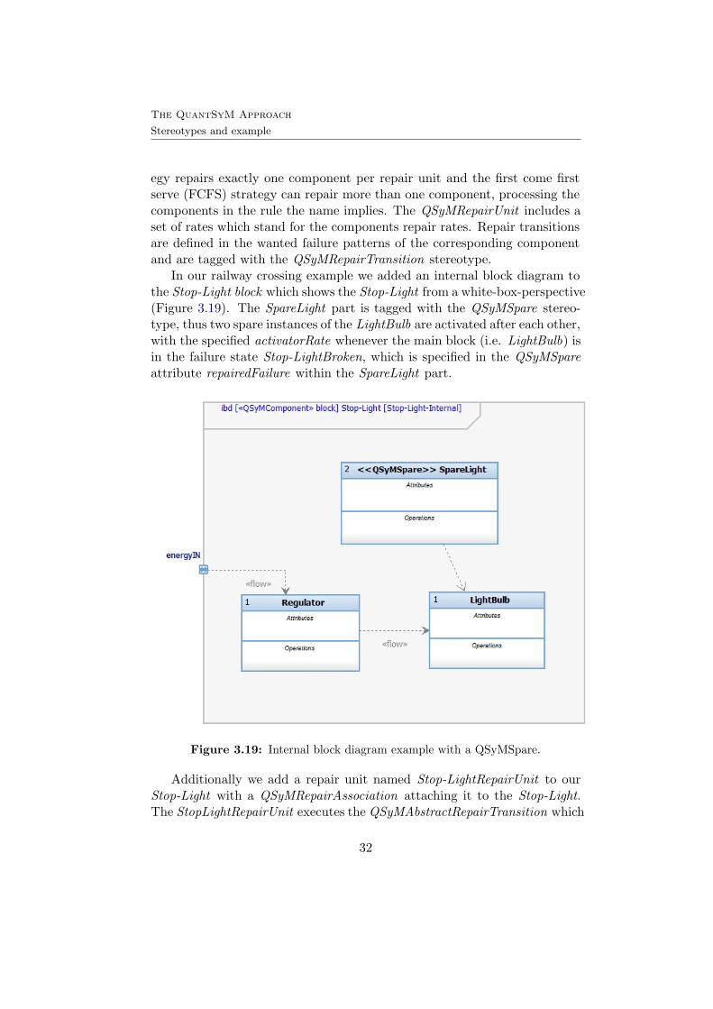
In our railway crossing example we added an internal block diagram tothe Stop-Light block which shows the Stop-Light from a white-box-perspective(Figure 3.19). The SpareLight part is tagged with the QSyMSpare stereo-type, thus two spare instances of the LightBulb are activated after each other,with the specified activatorRate whenever the main block (i.e. LightBulb) isin the failure state Stop-LightBroken, which is specified in the QSyMSpareattribute repairedFailure within the SpareLight part.
Figure 3.19: Internal block diagram example with a QSyMSpare.
Additionally we add a repair unit named Stop-LightRepairUnit to ourStop-Light with a QSyMRepairAssociation attaching it to the Stop-Light.The StopLightRepairUnit executes the QSyMAbstractRepairTransition which
32

The QuantSyM Approach
Stereotypes and example
brings the Stop-Light back to its normal behavior state machine with the inthe association specified repair rate. The resulting block diagram is shownin Figure 5.1.
Figure 3.20: Railway Crossing block diagram illustrating the RepairUnit mechanism.
33

The QuantSyM Approach
Discussion
3.6 Discussion
To see if our appliance of QuantUM to SysML maintains the in Section 3.1stated requirements, we discuss the degree of fulfillment in this section.
The first requirement (1) ”Applicability is provided on system and soft-ware architectures defined in SysML” has been maintained because theproposed extension is applicable to the SysML elements used in SysML.The second requirement (2) ”It is possible to specify dependability objec-tives/requirements.” is fulfilled throughout the added QSyMStateConfigura-tion stereotype, allowing the specification of state configurations which areused in QuantUM to specify ability objectives and requirements. Beside ofthat the possibility to define requirements for dependability is enabled. Theprofile does not differ from QuantUM in terms of the possibility to specifyall dependability characteristics needed for the analysis. Thus the require-ment (3) ”Means for the specification of dependability characteristics ofthe system components, such as failure modes and rates are existent” is alsomaintained. The adopt and changes to the QUMPropagationRule leading tothe QSyMPropagationRule for SysML assures the fulfillment of requirement(4). The same approach to handle means to ”model safety mechanisms suchas redundancy structures and repair management” with the introductionof the from QuantUM derived stereotypes: QSyMSpare, QSyMRepairUnit,QSyMRepairAssociation and QSyMRepairStrategies ensures the fulfillmentof requirement (5). Since the profile is extended to concepts which can besimply inferred from standards in system engineer, it should be easy to usethe profile for an experienced users in system engineering. Therefore wemaintain (requirement (6)) throughout our ”SysML - QuantUM” approach.Finally, the fact that we kept the basics of the QuantUM approach andextended it to the system engineering domain needs, shows that ”The addi-tional modeling with QuantSyM is as inexpensive as possible” (requirement(7)).1
1comparison to Florian-Leitner Fischer’s requirements
34

From Quantitative SysML to PRISM
4 From Quantitative SysML to PRISM
In order to analyse a system we modeled with the QuantSyM approach withthe model checker PRISM, the model has to be translated to the PRISMlanguage. In QuantUM there are already translation rules specified for theUML to translate its elements into the input language of the probabilisticmodel checker PRISM. In QuantSyM some translation rules are enhancedor changed so that the analysis possibilities are maintained. We will give ashort introduction on how the PRISM language is structured based on thePRISM Manual, for further information we refer to [22, 21, 10] .
A PRISM model consists of a number of modules which contain localvariables that constitute the state of the module at any given time. Amodules behaviour is described by a set of commands. These commandshave the following form:
[transition label] guard → rate1 : update1+...+ raten: updaten;
The guard is a predicate over all the variables in the model (including thosebelonging to other modules). Every update describes a transition whichthe module can make if the guard is true. The transitions are specified bygiving the new values of the variables in the module, possibly as a functionof other variables. Each update is also assigned a probability (or in somecases a rate) which will be assigned to the corresponding transition.
Codesample 4.1 shows an example module named samplemodule con-taining two variables, whereat variable 1 is of type Boolean and initiallytrue, and variable2 is numeric has initially the value 0. The guard (variable2 <= 12- 1) & (variable2-1 >=0 ) & (variable2 <2) needs to be true, sothat the update ( variable2’ = variable2 +1 ) is executed with the rate 0.8.Whenever the guard (variable 2 = 2 ) is true, the variable1 is set to false(variable1’=false) with the rate rate 1:0.
1 module samplemodule2 variable1: bool init true;3 variable2: [0..12] init 0;4 [Count] (variable2<=12−1) & (variable2 −1 >=0) &5 (variable2 < 2 ) −> 0.8 : ( variable2’ = variable2 + 1);6 [End] (variable2 = 2) −> 1.0: (variable1’ =false);7 endmodule
Codesample 4.1: a module in the PRISM language
35

From Quantitative SysML to PRISM
In QuantSyM, the translation rules for the QUMComponent, QUMFail-urePropagation, StateMachines and QUMRepairUnits are the same for thecorresponding QSyM elements, whereas the QSyMSpare is changed slightly.So far the QUMSpare stereotype is translated by adding a counter thatcounts the active spares, and one transition command that sets the moduleto the initial state, whenever any failure state is entered and the left sparecount is not zero. With the QSyMSpare we assume that not any Systemfailure can be replaced by a spare, therefore we restrict it to specific failurestates. The resulting translation rule is shown in Codesample 4.2
1 %module id% activespares: [0..%spares%]; >>2 [%module id% SpareActivated]3 (%module id% state =%#failurestate%)4 & (%module id% activespares < %module id% nuofspares)5 −> %rate%: ( %module id% state = %id init%)6 & (%module id% activespares = %module id% activespares + 1); >>
Codesample 4.2: PRISM translation rule for QSyMSpare
Besides the PRISM analysis model, the CSL properties to be analyzed areautomatically generated by the tool. The construction of the main CSLproperties can either be changed throughout the adding of further stateconfigurations or by just adding requirements (Chapter 3.5.6)to the stateconfigurations. In addition a way to manually specify CSL properties ispossible in the tool.
36

The resulting QuantSyM Tool
5 The resulting QuantSyM Tool
Within the scope of this thesis, the QuantUM tool has been restructuredand further improvements have been made. The possibility to parse SysMLmodels has been added to the tool, thus it is possible to translate SysMLmodels with the QSyM profile to the PRISM language. In our case studieswe used the IBM Rational Rhapsody v7.6 to annotate the model and exportit to the XML Metadata Interchange (XMI) format, a standard format forexchanging models and objects based on meta-models [20]. The QuantSyMtool has the same ”process chain” as the QuantUM tool. Therefore afterthe translation to the PRISM language, it generates the counterexamplesand computes the fault tree using the DiPro tool [15], and maps it on asequence diagram, stored in the XMI format. A Graphical user interfaceexists in order give the user information about the current progress and tohave the possibility to change several attributes in the QSyMComponents.An opportunity to choose between the different state configurations is alsoprovided, so a specific analysis can be made.
Figure 5.1: QuantUM / QuantSyM GUI
37

Case Studies
6 Case Studies
6.1 Airbag Control Unit
In order to evaluate our SysML profile, we applied it to the case studyfrom the automotive software domain, Florian Leitner-Fischer used in casestudies within his thesis: An Electronic Control Unit for an Airbag Sys-tem developed for TRW Automotive GmbH has been modeled in UML andthe QuantUM extension, with the objective of analyzing whether or notthe Airbag System is safe. Since we want to test the QuantSyM approachwe need to transfer the model to SysML, whereat we use the CASE toolIBM Rational Rhapsody. We will explain the resulting model based on theexplanations in [10].
In general 1 the airbag systems consists of three fundamental parts. Thefirst part are sensors: the System has different sensors detecting an impact.Acceleration sensors detect front, rear and side impacts whereas pressuresensors are in addition to side impact detection. Rollover accidents aredetected by so called angular rate or roll rate sensors. The second part isthe microcontroller: the microcontroller decides if the sensors informationstand for a crash situation. Unless the decision does not fall into the category”critical crash”, the airbags are not deployed. However, if they do fall in thatcategory, the third part: actuators control the deployment of the airbag.
In the in [10] modeled airbag system architecture, two acceleration sen-sors exist to detect front or rear crashes. Exactly one microcontroller isresponsible for the crash evaluation and an actuator controlling the airbagdeployment.
Two redundant mechanisms, the Field Effect Transistor (FET) and Fir-ing Application Specific Integrated Circuit (FASIC) secure the deployment ofthe airbag system whereas the FET is the power management of the airbagsquibs and the FASIC controls the squib itself. The FET has to be armedand therefore the FET-Pin high in order to provide the airbag enough elec-trical power to ignite. The FASIC has to receive an arm command fromthe microcontroller and a fire command in advance so that it will ignite theairbag squib.
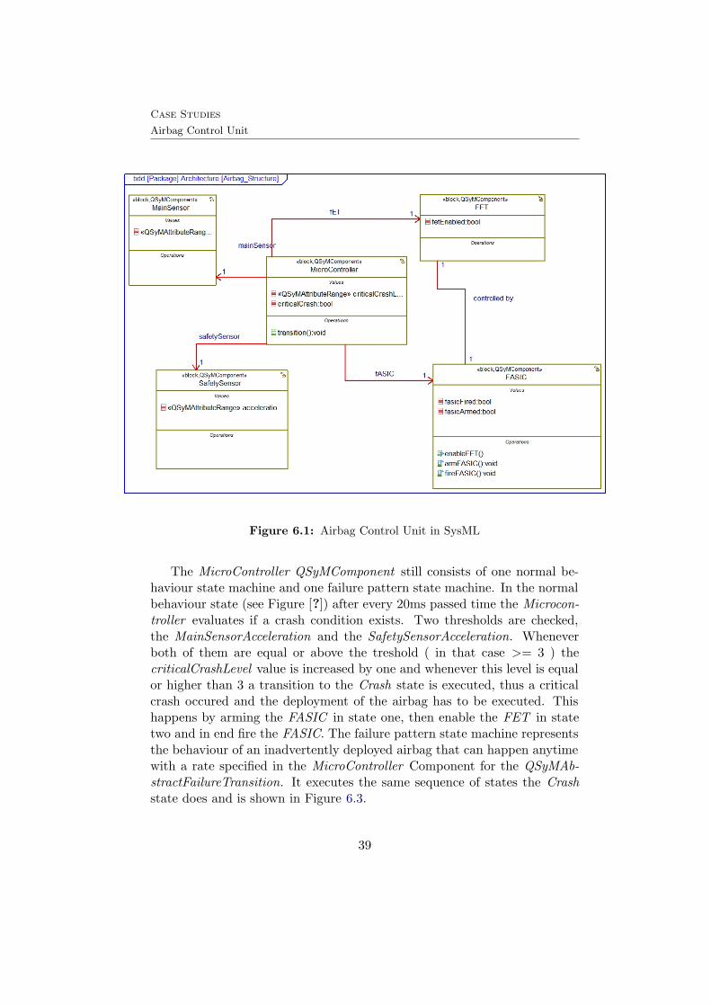
The structure of the QuantSyM model derived from the QuantUM modelis shown in Figure 6.1 and has not changed in its basic structure. Thebefore modeled classes: MainSensor, SafetySensor, MicroController, FETand FASIC are now changed to blocks and are tagged with the stereotypeQSyMComponent.
1Comparison to [19]
38
Case Studies
Airbag Control Unit
Figure 6.1: Airbag Control Unit in SysML
The MicroController QSyMComponent still consists of one normal be-haviour state machine and one failure pattern state machine. In the normalbehaviour state (see Figure [?]) after every 20ms passed time the Microcon-troller evaluates if a crash condition exists. Two thresholds are checked,the MainSensorAcceleration and the SafetySensorAcceleration. Wheneverboth of them are equal or above the treshold ( in that case >= 3 ) thecriticalCrashLevel value is increased by one and whenever this level is equalor higher than 3 a transition to the Crash state is executed, thus a criticalcrash occured and the deployment of the airbag has to be executed. Thishappens by arming the FASIC in state one, then enable the FET in statetwo and in end fire the FASIC. The failure pattern state machine representsthe behaviour of an inadvertently deployed airbag that can happen anytimewith a rate specified in the MicroController Component for the QSyMAb-stractFailureTransition. It executes the same sequence of states the Crashstate does and is shown in Figure 6.3.
39

Case Studies
Airbag Control Unit
Figure 6.2: MicroController normal behaviour state machine
40

Case Studies
Airbag Control Unit
Figure 6.3: MicroController failure pattern state machine
The FASIC Component has also one failure pattern (Figure 6.5) and onenormal behaviour state machine (Figure 6.6). The failure pattern for theFASIC has three different failure modes than can be entered after the failurestate is entered with the rate specified throughout the QSyMAbstractFailure-Transition. FASICStuckLow is the failure mode which occurs if FASIC getsnever fired (fasicFired=false) and therefore the airbag cannot be fired. FA-SICShortage is the failure mode where the mechanism which should protectthe FET is disabled and the airbag is fired. Finally the FASICStuckHighstate represents the failure mode whenever FET was enabled before and theFASIC is fired. Each of these failure modes is entered with a specific rate,defined in the corresponding QSyMFailureTransition. Additionaly, in orderto analyse the specific cases when the airbag is deployed inadvertently thefailure states where the FASIC is fired are tagged with a StateConfigurationnamed inadvertent deployment and the or-operator (Figure 6.4).
Figure 6.4: State configuration attributes
41

Case Studies
Airbag Control Unit
Figure 6.5: FASIC failure pattern state machine
Figure 6.6: FASIC normal behaviour state machine
42

Case Studies
Airbag Control Unit
There are no failure patterns specified for the sensors, because the goalfor Leitner-Fischer was to analyze the correct behavior of the other threecomponents. Therefore the final component interesting for the analysis is theFET. The normal behavior of the FET switches between the Enabled andDisabled state (Figure 6.7 ). Initially disabled, the Enabled state is triggeredwhenever the enableFET () operation is called. However, if it is already inthe Enabled state and the operation triggers the transition to the Disabledstate is taken. The failure pattern state machine of the FET, can be eitherin the FETStuckHigh or in the FETStuckLow state. whereat in the formercase the FET is enabled and in the latter case it is disabled, hence the vari-able fetEnabled has the corresponding value (Figure 6.8). The rate for theFET failure pattern is set throughout the QSyMAbstractFailureTransition.The rates for the failure modes are specified in the QSyMFailureTransitionsleading to them.
Figure 6.7: FET normal behaviour state machine
43

Case Studies
Airbag Control Unit
Figure 6.8: FET failure pattern state machine
As the resulting SysML model of the airbag system shows, there is noimportant difference to the model generated in the QuantUM approach. Soin the end we proceeded with the export of the model into an XMI file andimported it in the QuantSyM tool. The translation to the PRISM modelresults in the same amount of states and transitions and the same CSLformula has been generated by the tool. We have also compared the PRISMcode of the UML version with the SysML version and noted no differences.
In order to check the runtime for the computation of the counterexamples(Runtime CX) and the runtime for the fault tree generation (Runtime FT),we performed small tests on the QuantSyM tool. We kept the mission timeT=10, T=100, and T=1000 since we wanted to see if the results differ fromthe QuantUM runtime tests. The experiments were performed on a PC withan Intel Core i7-720QM processor with 2.8 Ghz and 8 GBs of RAM. Theresults of the test are shown in Table 1.
T Runtime CX ( sec.) Paths in CX Runtime FT ( sec.) Paths in FT10 580.247 (approx. 9,67 min) 738 2.21 5100 594.633 (approx. 9.91 min) 738 2.74 51000 772.319 (approx. 12.87 min) 738 3.12 5
Table 1: QuantSyM runtime test results for T=10, T=100 and T=1000
The results approve that the fault tree generation is build in a few sec-
44

Case Studies
Airbag Control Unit
onds whereas thec omputation of the counterexamples takes several minutes.Overall the running times keep the same for the QuantSyM approach of theairbag system.
45

Related Work
7 Related Work
Beside the QuantUM approach there exist several other work in the litera-ture that deal with quantitative analysis of UML models. However not manyare this we found only one other approach for probabilistic model checkingin SysML models. In this chapter we will discuss its procedural method andcompare it to QuantSyM, with the goal to find possible improvements orways to integrate the approach.
7.1 Probabilistic Model Checking of SysMLActivity Diagrams
In SysML, the in UML established activity diagrams have been extendedto probabilistic features. The authors of [23] use that feature and proposea translation from SysML activity diagrams into the input language of theprobabilistic model-checker PRISM.
The flow and control of data during the systems operations can be spec-ified in the activity diagram in SysML. The ”Activity Diagram Translation”then uses Markov decision process [25] (MDP) to analyze probabilistic andnon-deterministic behaviours. There is no introduction of new stereotypes,instead the translation to PRISM is ensured through an algorithm whichenables the transformation of activity diagrams directly into a MDP. There-fore there is no need to tag additional values and annotations to the model.The major drawback of this approach lies in the focus on the solely use ofthe activity diagram. Hence the only used aspect of the SysML is the behav-ioral structure and the requirement as well as structural aspects of SysMLare left behind.
The QuantSyM approach uses primarily state machines to model thebehavioral part of the system. Although we use the structural, behavioraland requirement aspect of SysML we generally use state machines and blockdiagrams for our approach. However, there are several modeling elementswe did not take in consideration (i.e. activity diagrams). Because of the factthat some of the control flows are difficult to model with state machines, theintegration of the activity diagram into the QuantSyM approach can be veryvaluable for system engineers. In order to achieve that, the basic concept ofthe state machine could be assigned to the activity diagram. For instanceobjects and activities could act like a state did in QuantSyM. Conditionalbranches could be realized by translating them as transitions with guardset cetera. At first glance the applicability seems to be possible, but furtherexamination is necessary to verify that.
46

Conclusion
8 Conclusion
8.1 Conclusion
The adaption of QuantUM to SysML has been successful. Therefore theintroduced QuantSyM profile allows to specify quantitative information inSysML models. The tool has been upgraded to the possibility to automati-cally translate a SysML model into the PRISM language and perform the aquantitative analysis with PRISM. Several additional stereotypes have beenadded to enhance the modeling possibilities to fulfill system engineers needs.The automatic generation of CSL properties has been further improved, andfurthermore, the process chain in QuantUM and the requirements to the toolhave been maintained. Hence the results keep the established fault trees,containing the crucial information about critical behavior.
Finally, the improved QuantSyM tool allows for a fully automated proba-bilistic analysis of SysML models, where the analysis level is complete hiddenfrom the user. The implementation of the approach on the case study showsthat the tool can be very useful to analyse system critical processes. Withthe fast translation of the model into PRISM and automatic generation ofCSL formulas, the tool can solve tasks where system engineers usually spenthours of time.
8.2 Future Work
In future work we plan to evaluate how the QuantSyM / QuantUM approachcan be integrated into an industrial process model. So far the model hasbeen created and exported to XMI with IBM Rational Rhapsody, but moreindustrial tools for life-cycle and requirements management exist. Hencewe plan to integrate the tool chain to other tools as well. In spite of allopportunities of the tool, the fact that the system engineering domain keepsdeveloping further and systems increase in complexity, the tool needs tobe tested for its applicability on real data and systems. Finally, we wantto analyze the possible integration of modeling elements that haven’t beenused for the analysis yet.
47

Appendix
9 Appendix
9.1 CD
48

References
[1] Aljazzar, H., Fischer, M., Grunske, L., Kuntz, M., Leitner-Fischer, F.,Leue, S.: Safety analysis of an airbag system using probabilistic FMEAand probabilistic counterexamples. In: QEST ’09: Proceedings of theSixth International Conference on Quantitative Evaluation of Systems,Los Alamitos, CA, USA, IEEE Computer Society (2009) 299-308
[2] Object Management Group: Unified Modeling Language. Specificationv2.3. http://www.uml.org (2010)
[3] The Object Management Group (OMG)http://www.omg.org/gettingstarted/gettingstartedindex.htm
[4] Current Version Specification of the Unified Modeling Languagea(UMLA R©) http://www.omg.org/spec/UML/2.4/
[5] Hinton, A., Kwiatkowska, M., Norman, G., Parker, D.: PRISM: Atool for automatic verification of probabilistic systems. In: TACAS’06: Proceedings of the 12th International Conference on Tools andAlgorithms for the Construction and Analysis of Systems. Lecture Notesin Computer Science, Springer (2006)
[6] PRISM website. http://www.prismmodelchecker.org/
[7] SysML Forum: SysML Specification (Draft), 2005.http://www.sysml.org
[8] IEC 61508: IEC(International Electrotechnical Commission) Func-tional safety of electrical/electronic/programmable electronic safety-related systems (2004)
[9] ISO 26262: International Organization for Standardization, Road Ve-hicles Functional Safety (Commitee Draft) (2008)
[10] Florian Leitner-Fischer : Quantitative Safety Analysis of UML ModelsMaster Thesis for the degree Master of Science (M.Sc.) in InformationEngineering
[11] Kwiatkowska, M., Norman, G., Parker, D.: Probabilistic Model Check-ing. In: Modeling and verification of parallel processes. Summer school.(2001) 189204

REFERENCES
REFERENCES
[12] A. Aziz, K. Sanwal, V. Singhal, R. K. Brayton: Verifying continuous-time Markov chains. In: CAV ’96: Proceedings of the 8th InternationalConference on Computer Aided Veri
cation. Volume 1102., New Brunswick, NJ, USA, Springer Verlag LNCS(1996) 269276
[13] Baier, C., Haverkort, B., Hermanns, H., Katoen, J.P.: Model-checkingalgorithms for continuous-time Markov chains. IEEE Transactions onSoftware Engineering 29 (2003)
[14] The Current State of Model Based Systems Engineering: Results fromthe OMG SysML Request for Information 2009 8th Conference on Sys-tems Engineering Research March 17-19, 2010, Hoboken, NJ Paper1569270919
[15] Aljazzar, H., Leue, S.: Debugging of dependability models using inter-active visualization of counterexamples. In: QEST ’08: Proceedings ofthe Fifth International Conference on the Quantitative Evaluation ofSystems, IEEE Computer Society Press (2008)
[16] Baier, C., Haverkort, B., Hermanns, H., Katoen, J.P.: Model-checkingalgorithms for continuous-time Markov chains. IEEE Transactions onSoftware Engineering 29 (2003)
[17] INCOSE: What is Systems Engineering? http://www.incose.org
[18] Sanford Friedenthal, Alan Moore, Rick Steiner:OMG Systems ModelingLanguage (OMG SysMLa)Tutorial September, 2009
[19] Pilatus, K. Technische Funktionsweise und Aufbau von Airbags.Verkehrsunfall und Fahrzeugtechnik 38 (2000) pp. 124 127 (5).
[20] Object Management Group: XML Metadata Interchange (XMI),v2.1.1. http://www.omg.org/technology/documents/formal/xmi.htm(2007)
[21] Hinton, A., Kwiatkowska, M., Norman, G., Parker, D.:The prism language - semantics. (Available from URLhttp://www.prismmodelchecker.org/doc/semantics.pdf)
[22] [KNP11] Marta Kwiatkowska, Gethin Norman and David Parker.PRISM 4.0: Verification of Probabilistic Real-time Systems. InProc. 23rd International Conference on Computer Aided Verification(CAV11), volume 6806 of LNCS, pages 585-591, Springer, 2011.
50

REFERENCES
REFERENCES
[23] Verification and Validation in Systems Engineering Assessing UM-L/SysML Design Models Debbabi, M., Hassaıne, F., Jarraya, Y.,Soeanu, A., Alawneh, L. 1st Edition., 2010, XXVI, 270 p. 95 illus.
[24] Systems Engineering mit SysML/UML: Modellierung, Analyse, DesignTom Weilkiens, Heidelberg 2. Auflage, 2008
[25] Handbook of Markov Decision Processes Methods and Applications Eu-gene A. Feinberg,SUNY at Stony Brook, USA, Adam Shwartz,TechnionIsrael Institute of Technology, Haifa, Israel
51