QUANTIFYING MUD CONTAMINATION WITHOUT ADDING TRACERS · In one well a water zone is encountered, in...
12
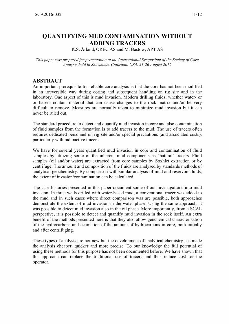
SCA2016-032 1/12 QUANTIFYING MUD CONTAMINATION WITHOUT ADDING TRACERS K.S. Årland, OREC AS and M. Bastow, APT AS This paper was prepared for presentation at the International Symposium of the Society of Core Analysts held in Snowmass, Colorado, USA, 21-26 August 2016 ABSTRACT An important prerequisite for reliable core analysis is that the core has not been modified in an irreversible way during coring and subsequent handling on rig site and in the laboratory. One aspect of this is mud invasion. Modern drilling fluids, whether water- or oil-based, contain material that can cause changes to the rock matrix and/or be very difficult to remove. Measures are normally taken to minimize mud invasion but it can never be ruled out. The standard procedure to detect and quantify mud invasion in core and also contamination of fluid samples from the formation is to add tracers to the mud. The use of tracers often requires dedicated personnel on rig site and/or special precautions (and associated costs), particularly with radioactive tracers. We have for several years quantified mud invasion in core and contamination of fluid samples by utilizing some of the inherent mud components as "natural" tracers. Fluid samples (oil and/or water) are extracted from core samples by Soxhlet extraction or by centrifuge. The amount and composition of the fluids are analysed by standards methods of analytical geochemistry. By comparison with similar analysis of mud and reservoir fluids, the extent of invasion/contamination can be calculated. The case histories presented in this paper document some of our investigations into mud invasion. In three wells drilled with water-based mud, a conventional tracer was added to the mud and in such cases where direct comparison was are possible, both approaches demonstrate the extent of mud invasion in the water phase. Using the same approach, it was possible to detect mud invasion also in the oil phase. More importantly, from a SCAL perspective, it is possible to detect and quantify mud invasion in the rock itself. An extra benefit of the methods presented here is that they also allow geochemical characterization of the hydrocarbons and estimation of the amount of hydrocarbons in core, both initially and after centrifuging. These types of analysis are not new but the development of analytical chemistry has made the analysis cheaper, quicker and more precise. To our knowledge the full potential of using these methods for this purpose has not been documented before. We have shown that this approach can replace the traditional use of tracers and thus reduce cost for the operator.
Transcript of QUANTIFYING MUD CONTAMINATION WITHOUT ADDING TRACERS · In one well a water zone is encountered, in...
SCA2016-032 1/12
QUANTIFYING MUD CONTAMINATION WITHOUT ADDING TRACERS
K.S. Årland, OREC AS and M. Bastow, APT AS
This paper was prepared for presentation at the International Symposium of the Society of Core Analysts held in Snowmass, Colorado, USA, 21-26 August 2016
ABSTRACT An important prerequisite for reliable core analysis is that the core has not been modified in an irreversible way during coring and subsequent handling on rig site and in the laboratory. One aspect of this is mud invasion. Modern drilling fluids, whether water- or oil-based, contain material that can cause changes to the rock matrix and/or be very difficult to remove. Measures are normally taken to minimize mud invasion but it can never be ruled out. The standard procedure to detect and quantify mud invasion in core and also contamination of fluid samples from the formation is to add tracers to the mud. The use of tracers often requires dedicated personnel on rig site and/or special precautions (and associated costs), particularly with radioactive tracers. We have for several years quantified mud invasion in core and contamination of fluid samples by utilizing some of the inherent mud components as "natural" tracers. Fluid samples (oil and/or water) are extracted from core samples by Soxhlet extraction or by centrifuge. The amount and composition of the fluids are analysed by standards methods of analytical geochemistry. By comparison with similar analysis of mud and reservoir fluids, the extent of invasion/contamination can be calculated. The case histories presented in this paper document some of our investigations into mud invasion. In three wells drilled with water-based mud, a conventional tracer was added to the mud and in such cases where direct comparison was are possible, both approaches demonstrate the extent of mud invasion in the water phase. Using the same approach, it was possible to detect mud invasion also in the oil phase. More importantly, from a SCAL perspective, it is possible to detect and quantify mud invasion in the rock itself. An extra benefit of the methods presented here is that they also allow geochemical characterization of the hydrocarbons and estimation of the amount of hydrocarbons in core, both initially and after centrifuging. These types of analysis are not new but the development of analytical chemistry has made the analysis cheaper, quicker and more precise. To our knowledge the full potential of using these methods for this purpose has not been documented before. We have shown that this approach can replace the traditional use of tracers and thus reduce cost for the operator.

SCA2016-032 2/12
INTRODUCTION In order to obtain correct and representative results from analysis of core samples from a petroleum reservoir one must assure (and not merely assume) that the samples have not been irreversibly changed. Drilling may cause mechanical changes (fracturing, disintegration) and fluid changes by mud invasion. During tripping out of hole, the core will normally (unless special precaution is taken) experience reduced pressure and temperature. This may lead to precipitation of asphaltenes and wax plus expulsion of fluid. During storage further changes may take place by diffusion and evaporation. Therefore, it is important to drill plugs as early as possible to avoid further contamination [1]. Plugging and slabbing should be done without introducing fluids which may adsorb and/or interfere with the core analysis. For tests that involve more than one fluid (resistivity index, relative permeability), wettability is the single most important property [2]. If the initial wetting condition is not conserved or cannot be restored the outcome of core analysis may be erroneous and highly misleading [3]. It is documented that mud invasion can cause changes to rock properties and that some mud types can cause irreversible changes [4]. When planning a core analysis program, it is essential to know what mud has been used for coring and check if mud invasion has taken place [5]. The standard procedure to obtain this information is to add tracers to the mud. Depending on the requirements, the tracer could be either in the water phase or in the oil phase. The use of tracers often requires dedicated personnel on rig site and/or special precautions (and associated costs), particularly with radioactive tracers. Jones and Burger [6] presented a case where mud invasion was estimated by mass spectrometry analysis of water centrifuged from core samples and data processing by principal components analysis (PCA) and multivariate curve resolution (MCR). A more general approach, by using inherent mud components as “natural” tracers to detect and quantify mud invasion was mentioned by Årland et al. [5]. This method will be demonstrated in this work. Besides, using geochemical methods, additional data of great interest can be found. An extension of this approach/method to evaluation of cleaning of core and wettability tests will be the subject of a forthcoming paper. In the following we will discuss the results from five exploration/appraisal wells drilled in recent years on the Norwegian Continental Shelf, see table 1. All wells found oil in sandstone reservoirs. In one well a water zone is encountered, in another well a gas zone appeared. Two wells are drilled with oil-based mud (OBM) with different base oil. The remaining wells are drilled with water-based mud (WBM) with KCl and glycol. Thiocyanate (SCN) is used as tracer in these three wells. In table 1, “Lubricant” is the fluid used by the core laboratory for drilling of plugs.

SCA2016-032 3/12
Table 1: Overview of studies for mud invasion
Company Well Fluidin-situ
Mud(base)
Mudtype/baseoil
Tracerinmud
Lubri- Samplesforinvasioncant
A A1 O O EDC95/11™ CC_o+COB B1 O W Glycol_KCl SCN Brine CC_o+CO+CWB B2 O W Glycol_KCl SCN CC_o+CO+CWC C1 O&W W Glycol_KCl SCN Clairsol™ CC_o+CW+CC_wC C2 O&G O XP-07™ Clairsol™ CO
Legend: O,GandW:oil,gasandwater COandCW:Centrifugedoilandwater
CC_o/w:extractionofoil/waterfromcorechips,plugsetc.
METHOD Inherent Mud Components that can be used as “Natural Tracers” Oil-based mud: here the base oils can be used as "tracers". Base oils are typically of characteristic composition, either narrow distillation range diesel-like (as EDC 95/11 (table 1)), enhanced mineral oils, or synthetic oils (esters, olefins or linear n-alkane like XP-07 (table 1)). See Gas Chromatograms (GC) of EDC 95/11 and XP-07 in figure 1.
Figure 1: Gas Chromatography (GC) of OBM with EDC 95/11 (left) and XP-07 (right) base oil. Water-based mud: often glycol is added (typically 4 %) to provide enhanced inhibition (Glycol_KCl in table 1). Glycol or polyglycols can be used as "tracers". Glycols are all dihydric alcohols and ethylene glycol is one of the simplest polyalkylene glycols widely used in anti-freezes and as engine coolants. Drilling fluids are commercial products subjected to patents and exactly which polyalkylene glycols are present in individual products is generally not available. GC analyses typically suggest homologous series.
Well: 6506/11-9 SDepth: 4774 m RKBSample type: MudAPT-ID: 108983 Analysis: GC-FIDAnalysis date: 01-Mar-13
Abundance:FID: 3.401e+6
10 min. 20 30 40 50 60 70 80 90 100 110 120 130 140
100.00
75.00
50.00
25.00
IS 2
,2,4
-TM
C5
n-C
7
n-C
9
n-C
10
n-C
11
n-C
12
n-C
13
n-C
14
n-C
15
n-C
16n-
C17
n-C
18n-
C19
n-C
20n-
C21
n-C
22n-
C23
n-C
24n-
C25
n-C
26n-
C27
n-C
28
Well: 35/9-10 SDepth: 3200 m RKBSample type: MudAPT-ID: 127168 Analysis: GC-FIDAnalysis date: 09-Jan-14
Abundance:FID: 2.603e+7
10 min. 20 30 40 50 60 70 80 90 100 110 120 130 140
4.0e+6
8.0e+6
1.2e+7
1.6e+7
2.0e+7
2.4e+7
IS tr
ans-
2-H
epte
ne
n-C
3n-
C5
n-C
6
n-C
7
n-C
9 n-C
10
n-C
11
n-C
12
n-C
13
n-C
14
n-C
15n-
C16
n-C
17n-
C18
n-C
19n-
C20
n-C
21n-
C22
n-C
23n-
C24
n-C
25n-
C26
n-C
27n-
C28
n-C
29
EDC 95/11 XP-07
n-C13
n-C13
n-C12
n-C20
n-C17

SCA2016-032 4/12
Polyglycol is 100 % miscible with water but the solubility in oil is very variable, depending among other things, the amount of aromatics and polar components. The amounts of drilling fluid can be estimated based upon quantification of the dominant polyglycol peaks in whole extract GC of the oil phase, as illustrated in figure 2.
Figure 2: GC of WBM with polyglycols (left) and GC of Core extract from well B1(right). In the latter, there are very little mud filtrate (5 %) In WBM (and to some extent OBM) salts are added. WBM with glycols have KCl in high concentration, typically 90 g/l. If the ion analysis gives a surplus of these salts, this is a good indicator of mud invasion. Analytical Methods Geochemical analyses are carried out in accordance with NIGOGA [7] recommendations. For oil and rock samples preferred minimum sample amounts are about 5 ml and 20 g respectively, although smaller samples can be used, dependent upon the range of analyses. Rock samples are crushed and therefore may have any shape. Rock samples are solvent extracted by Soxhlet method. The amount of extractable organic matter (EOM) is calculated from the weight of a 10% aliquot of the extract evaporated to dryness. Oil samples from well tests or centrifuged from core samples may be analysed directly. The hydrocarbon fraction of muds is extracted by solvent as for rock samples. GC analyses may be carried out on whole oils and whole extracts or on separated alkane fractions. It is also common practice to perform a hydrocarbon group/SARA analysis [7]. Asphaltenes are defined as components in the crude oil that are soluble in toluene and insoluble in pentane, hexane and heptane [8]. According to NIGOGA, asphaltene
Well: 16/2-7Depth: 1949 m RKBSample type: COPLFraction: EOMAPT-ID: 92977 Analysis: GC-FIDAnalysis date: 13-Dec-11Int. std. added: 100 µl
Abundance:FID: 2.408e+6
10 min. 20 30 40 50 60
0.43
0.32
0.21
0.106
d42-
C20
(IS
)
n-C
10
n-C
11
n-C
12i-
C13 i-
C14
n-C
13
i-C
15n-
C14
i-C
16n-
C15 n-
C16
i-C
18n-
C17
Pr
n-C
18P
h
n-C
19
n-C
20
n-C
21
n-C
22
n-C
23
n-C
24
n-C
25
n-C
26
n-C
27
n-C
28
n-C
29
n-C
30n-
C31
n-C
32n-
C33
n-C
34n-
C35
n-C
36
Well: 35/9-8Depth: 2754 m RKBSample type: MudFraction: EOMAPT-ID: 132786 Analysis: GC-FIDAnalysis date: 19-May-14Int. std. added: 100 µl
Abundance:FID (pA): 1.341e+3
10 min. 20 30 40 50 60 70
1.0e+2
2.0e+2
3.0e+2
4.0e+2
5.0e+2
6.0e+2
7.0e+2
8.0e+2
9.0e+2
1.0e+3
1.1e+3
1.2e+3
1.3e+3
d42-
C20
(IS
)
n-C
11
n-C
12i-
C13
i-C
14n-
C13
i-C
15n-
C14
n-C
15
n-C
16i-
C18
n-C
17Pr n-
C18
Ph n-C
19
n-C
21
n-C
22
n-C
24
Polyglycols
Internal standard
n-C13
n-C
13
n-C
16
SCA2016-032 5/12
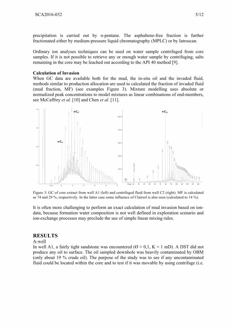
precipitation is carried out by n-pentane. The asphaltene-free fraction is further fractionated either by medium-pressure liquid chromatography (MPLC) or by Iatroscan. Ordinary ion analyses techniques can be used on water sample centrifuged from core samples. If it is not possible to retrieve any or enough water sample by centrifuging, salts remaining in the core may be leached out according to the API 40 method [9]. Calculation of Invasion When GC data are available both for the mud, the in-situ oil and the invaded fluid, methods similar to production allocation are used to calculated the fraction of invaded fluid (mud fraction, MF) (see examples Figure 3). Mixture modelling uses absolute or normalized peak concentrations to model mixtures as linear combinations of end-members, see McCaffrey et al. [10] and Chen et al. [11].
Figure 3: GC of core extract from well A1 (left) and centrifuged fluid from well C2 (right). MF is calculated as 74 and 29 %, respectively. In the latter case some influence of Clairsol is also seen (calculated to 14 %). It is often more challenging to perform an exact calculation of mud invasion based on ion-data, because formation water composition is not well defined in exploration scenario and ion-exchange processes may preclude the use of simple linear mixing rules. RESULTS A-well In well A1, a fairly tight sandstone was encountered (Ø ≈ 0,1, K ≈ 1 mD). A DST did not produce any oil to surface. The oil sampled downhole was heavily contaminated by OBM (only about 19 % crude oil). The purpose of the study was to see if any uncontaminated fluid could be located within the core and to test if it was movable by using centrifuge (i.e.
Well: 6506/11-9 SDepth: 4754.38 m RKBSample type: COCHAPT-ID: 108989 Analysis: GC-FIDAnalysis date: 09-Mar-13Int. std. added: 100 µl
Abundance:FID: 4.193e+6
10 min. 20 30 40 50 60 70
0.30
0.22
0.148
0.074
d4
2-C
20
(I
S)
n-
C1
0 n-
C1
1
n-
C1
2i-
C1
3 i-C
14
n-
C1
3
i-C
15
n-
C1
4
i-C
16
n-
C1
5 n-
C1
6
i-C
18
n-
C1
7P
r
n-
C1
8P
h
n-
C1
9
n-
C2
0
n-
C2
1
n-
C2
2
n-
C2
3
n-
C2
4
n-
C2
5
n-
C2
6
n-
C2
7
n-
C2
8
n-
C2
9
n-
C3
0
n-
C3
1
n-
C3
2
n-
C3
3
n-
C3
4
n-
C3
5
n-
C3
6Well: 35/9-10 SDepth: 3158.15 m RKBSample type: Centrifuge fluidAPT-ID: 126779 Analysis: GC-FIDAnalysis date: 08-Jan-14
Abundance:FID: 9.955e+6
10 min. 20 30 40 50 60 70 80 90 100 110 120 130 140
1.8e+6
3.6e+6
5.4e+6
7.2e+6
9.0e+6
IS tr
ans-
2-H
epte
ne
n-C
3n-
C4
n-C
5
n-C
7
n-C
8
n-C
9
n-C
10
n-C
11
n-C
12
n-C
13
n-C
14
n-C
15n-
C16
n-C
17n-
C18
n-C
19n-
C20
n-C
21n-
C22
n-C
23n-
C24
n-C
25n-
C26
n-C
27n-
C28
n-C
29n-
C30
n-C
31n-
C32
n-C
33
n-C
34
n-C
35
n-C
36
n-C13n-C17
n-C13

SCA2016-032 6/12
either “producible” or “residual”). For that purpose, one whole core seal-peel (SP) sample was used.
Figure 4: Schematic illustration of sampling of the SP (cross section along core axis to the left). A 1“ disc (blue) is cut in the middle and later sampled as seen to the right. 1,5” plugs are drill axially in the remaining two halves of the SP Main results: Mud filtrate was seen throughout the cross-section of the core, but less in the interior than at the outer edges of the core (figure 5a). The crude oil fraction in the centre of the core was higher than in the downhole fluid samples (27 % vs 19 %, figure 5a). Although the EOM decreases towards the centre of the core, the absolute crude oil content (in mg/g rock) at the centre is about three times the content at the edges.
Figure 5: Percentage crude oil found in core samples (5a – left) and in fluids (5b- right) By centrifuging the 1,5” plugs, about 50 % of the EOM is removed, relatively more filtrate than crude oil (figure 5b). While the bulk composition of the centrifuged hydrocarbon (HC) is similar to the produced HC, the fluid remaining in the core is different: centrifugation preferentially removes alkanes, whereas the other fractions, particularly the polars and asphaltenes, seem to be more strongly attached to the core material, see figure 6.
0
2
4
6
8
10
0
5
10
15
20
25
30
0 2 4 6 8
EOM(m
g/grock)
Crud
eoil(%)
Coresampleno
VariaNonof%crudeoilandEOMintheSPdisksample
Crudeoil(%) EOM(mg/gRock)
a
23.5
75
19
01020304050607080
Centrifugedfromcore
ExtractedfromcoreaSercentrifuge
Fromwell
%Crudeoilinfluids b

SCA2016-032 7/12
Figure 6: Results from fractionating fluid from different sources (F_W: oil from well, F_C_a: oil from core (average), ET_a: oil from endtrim (average), CSx: core sample no x, ref. figure 4). B-wells The B wells are both from the same reservoir, with good properties (Ø ≈0,3, K ≈ 10 D) and a weakly consolidated matrix. The core samples (all loose sand) were from above and below the official free water level (FWL). SCN had been added to the mud as tracer for the water phase. In this case, an uncontaminated oil sample was available. The purpose of the study was to:
a) See if there are variations in HC content and composition across the FWL. b) Quantify the degree of mud invasion (determine MF). c) Estimate how much of the HC is removed by centrifugation. d) Look for indication of fractionation of the oil due to centrifugation.
For well B2, fresh (native) samples were extracted to determine the amount of original oil in the sample. For both wells sands were centrifuged and the fluid produced as well as the oil remaining in the sample were analysed. Main results: in well B2 there is almost no variation in oil content in the sand with depth, irrespectively above or below FWL (zero on the abscissa in figure 7). Here the MF in oil is also plotted. MF is less below FWL than above. The rock properties are uniform in this depth interval. The range of analyses carried out (see isoprenoid/n-alkane ratios, figure 8) did not reveal any change in oil composition across FWL
60 65 70 75 80 85 90 95 100
CS1
CS2
CS3
CS4
CS5
CS6
CS7
ET_a
F_C_a
F_W
Mud
ProcentageoftheHCgroups
Samples
SARAdata
Alkanes
AromaZcs
Polars
Asphaltenes

SCA2016-032 8/12
Figure 7: EOM and MF in fresh core versus depth in well B2
Figure 8: Comparison of composition of oil extracted from fresh core samples from well B2 using isoprenoid/n-alkane ratios Centrifuging gave mostly water (typically 5 ml versus about 1 ml or less oil). MF in water, based on the SCN tracer, and in oil are shown in figure 9a below (too little oil for reliable measurements in well B2). It is seen that the MF in water is generally higher than in the oil phase. The high values for MF in oil at depth – 2 and 0 is probably a result of preparation procedure (solvent extraction of oil-water mixture recovers also polyglycols).
Figure 9: MF in fluid centrifuged from core (9a-left) and in fluid remaining in core (9b -right)
0.000.050.100.150.200.250.300.350.40
5.0
6.0
7.0
8.0
9.0
10.0
-13 -11 -9 -7 -5 -3 -1 1 3 5 7
MF(frac)
EOM(m
g/grock)
Coredepth(mbelowFWL)
EOM_org
MFc_org
00.10.20.30.40.50.60.70.80.9
iC13/nC12 iC14/nC13 iC15/nC14 iC16/nC15 iC18/nC16 Pri/nC17 Phy/nC18
RaNo
ofisopren
oid/n-alkan
concen
traN
on
B2_-11
B2_-8
B2_-3
B2_0
B2_5
B2_7
0
0.5
1
-7 -5 -3 -1 1 3 5 7
MF(frac)
Coredepth(mbelowFWL)
MFincentrifugedoilandwater
MFo_b1 MFw_b1
a
0.0
0.2
0.4
-13 -11 -9 -7 -5 -3 -1 1 3 5 7
MF(frac)
Coredepth(mbelowFWL)
MFinoilremaininginCore
MFc_b1 MFc_b2
b

SCA2016-032 9/12
By comparing the two plots in figure 9, one can conclude that MF in core material (figure 9b) is generally less than in the fluids centrifuged from it (figure 9a). Based on data from well B2 the fraction removed by centrifugation varies between 50 and 80 % with one exception (only 8% removed). The amount of oil remaining after centrifugation, expressed as mg/g rock, is low and at the same level as found in well A1. Three samples were analysed twice, with good reproducibility. Whereas oil from well testing has about 4 % asphaltenes, the centrifuged oil has none and the oil left in the core after centrifuging has almost 7 %. Otherwise the fluids are fairly similar. C-wells The C-wells were drilled into good sandstone reservoir (Ø ≈ 0,22, K ≈ 600 mD). In well C1 coring was extended into the water zone. The same type of WBM and tracer as in the B-wells were used. In well C2, a shallow gas zone was also cored. OBM with the synthetic base oil XP-07 was used during coring. The purpose of the study was to record the mud invasion and to have a basis for evaluation of the efficiency of core cleaning. In well C1, fluid was centrifuged and extracted/leached from core samples. Both oil and water/salts were analysed, unfortunately not on the same samples. In well C2 plugs were centrifuged and only oil retrieved and analysed. Main results: The mud invasion calculation for oil became more challenging as Clairsol were used as lubricant during plugging of the SP’s, i.e. one had to discriminate between three sources of HC. The fact that these wells encountered water and gas zones was not reported to the laboratory: the analysis never-the-less pinpointed these zones correctly. The MF in oil (MFo_gc in figure 10) was fairly low in well C1 with the exception of one sample from the water zone.
Figure 10: MF in fluid centrifuged from core in well C1 based on GC for oil and SCN tracer for water. Also shown are ratio of K in sample to K in formation water
0
100
200
300
400
500
600
700
800
900
0.00.10.20.30.40.50.60.70.80.91.0
-80 -60 -40 -20 0 20 40 60
Ks/Kfw
(frac)
MF(frac)
Coredepth(mbelowFWL)
MFw_scn
MFo_gc
Ks/Kfw

SCA2016-032 10/12
MF in water samples based on measurements of SCN (MFw_scn) gave very variable results, from almost no invasion to severe (almost complete) invasion. Analysis of salt extracted from D&S plugs demonstrated severe/complete flooding (values of K one order of magnitude greater than in FW, see Ks/Kfw above). Centrifugation of the samples from well C2 gave the results shown in table 2. The gas zone was shown be to severely flooded with mud filtrate. Table 2: The fraction of crude oil, base oil (XP-07) and lubricator (Clairsol) found in fluid centrifuged from core samples from well C2. D_c2 Crude oil Base oil Lubricator (m below GOC) (frac) (frac) (frac) -10,8 0 0,89 0,11 -5,9 0 0,97 0,03 78,15 0,57 0,29 0,14 80,2 0,51 0,32 0,17 91,2 0,29 0,57 0,14 92,15 0,65 0,08 0,27 DISCUSSION We have demonstrated that mud invasion can be detected and quantified, whether OBM or WBM is used. For OBM the base oil is readily identified. In this study, WBM with glycol has been used and the glycol is normally readily detected in the oil phase. In water samples a surplus of the salts added is seen. Quantification of mud invasion is fairly straight-forward for OBM, provided an uncontaminated oil from the reservoir is available and that oil is not used for plugging and slabbing. But even in cases where one has to discriminate between three types of HC (crude oil, base oil and lubricator) as for well C2, it is possible to obtain reasonable results. In the wells drilled with OBM (A1 and C2) no ordinary tracer was added, therefore a direct comparison is not possible. However, the results (variation radially and fraction mobilised by centrifuging in A1, and the extent of invasion in the gas zone of well C2) demonstrates that the method works. Quantification of mud invasion with natural tracers is more challenging for WBM. In this study we have selected wells with WBM where a tracer has been added to the water phase. Assuming ideal mixing and a stable concentration of tracer in the mud, it is simple to arrive at a number for MF. For B-wells (figure 9) and C1 (figure 10) we see that the MF in the water phase is in most cases higher than in the oil phase. This is as expected based on the difference in solubility of polyglycol in water and oil. Calculation of MF in water from ion analysis is not straight-forward as interaction between ions in water and rock surface may take place. This is the reason why applying MF found in tracer directly often gives unreasonable results. In some cases, modelling can be performed [12].

SCA2016-032 11/12
One of the reviewers [13] suggested using the ratio of Na and K as indicator for mud contamination and compare with data from the SCN tracer. The results from the three wells (B1, B2 and C1) is shown below.
Figure 11: Na/K ratio vs. contamination calculated from the SCN tracer. Mud data is very similar, ranging from 0,14 to 0,21. Na/K for uncontaminated formation water is in the range 60 – 64 for the B wells and about 180 (uncertain) for well C2. Although some scatter, there is a clear tendency of Na/K decreasing with increasing contamination – as calculated from SCN data. In this work we have demonstrated that the properties of the oil remaining in the core after centrifuging (i.e. production) can be different from the oil that is centrifuged/produced. In general, polars and asphaltenes seem to be retained in the core. This is in line with data published within the geochemical community (Bennett et al [14]). We have also seen that mud filtrate is more easily removed from core than the in-situ crude oil. CONCLUSION This work demonstrates that components in the mud can be used as “natural” tracers, eliminating the need to add specific tracers to the mud. Besides reducing cost, this approach has the following important aspects:
1. Can work with small fluid samples and sample from cores of any shape. 2. Both oil and water samples may be analysed. 3. Preliminary identification of oil type. 4. Detect any major difference in produced and in-place oil composition.
ACKNOWLEDGEMENTS We thank Adam Boughey of NOV Wellbore Technologies for suggesting to publish this work and asking some critical questions. We thank Trond Saksvik and Trygve Maldal of
0.00.10.20.30.40.50.60.70.80.9
0.0 0.1 0.2 0.3 0.4 0.5 0.6 0.7 0.8 0.9 1.0
Na/KraNo
RaNoofSCNisampleandinmud
WellB2 WellC1 WellB1
SCA2016-032 12/12
OREC for their comments on a preliminary version of the manuscript and the reviewers (Kevin Flynn and John Shafer) for their detailed comments and helpful suggestions. Appreciation is expressed to the companies that have released the data used in this work. Any views and/or opinions in this paper are those of the authors and are not necessarily shared by the companies. REFERENCES 1. Ringen, J.K. et al.: “Reservoir Water Saturation Measured on cores: Case Histories
and Recommendations”, SCA-9906 2. Morrow, N.R., 1990. “Wettability and its Effect on Oil Recovery” JPT 42, 1476–1484
(Dec.) 3. Kelleher, H.A., Braun, E.M., Milligan, B.E., Glotzbach, R.C., Haugen, E., 2007.
“Wettability Restoration in Cores Contaminated by Fatty Acid Emulsifiers” SCA2007-03
4. Buckley, J.S., Morrow, N.R., 2006. “Wettability and Prediction of Oil Recovery from Reservoirs Developed with Modern Drilling and Completion Fluids”, Report for the United States Department of Energy (DOE), BC-15164
5. Årland, K.S; Pruno, S and Skjæveland, O “Advanced RCA- Bridging the Gap between Routine and Special Core Analysis”, SCA2014-094
6. Jones, C. and Burger, J. “Results of a Tracerless Core Invasion Study using Multivariate Curve Resolution”, SCA2004-38
7. Weiss H.M., Wilhelms A., Mills N., Scotchmer J., Hall P.B., Lind K. and Brekke T., 2000. NIGOGA - The Norwegian Industry Guide to Organic Geochemical Analyses. Edition 4.0 Published by Norsk Hydro, Statoil, Geolab Nor, SINTEF Petroleum Research and the Norwegian Petroleum Directorate.
8. Zhang, Y, Wang, J, Morrow, N.R. and Buckley, J.S., 2005. “Effect of Synthetic Drilling Fluid Base Oil on Asphaltene Stability and Wetting in Sandstone Cores”. Energy & Fuels , 19, 1412 - 1416
9. API Recommended Core Analysis Practices 40, Chapter 7.7.2. 10. McCaffrey M.A., Baskin D.K., Patterson B.A., Ohms D.H., Stone C. and Reisdorf D.,
2012. Oil fingerprinting dramatically reduces production allocation costs. World Oil, March 2012, p. 55-59.
11. Chen J., Deng C., Song F. and Zhang D., 2007. A mathematical calculation model using biomarkers to quantitatively determine the relative source proportion of mixed oils. Acta Geologica Sinica, v. 81, p. 817-826.
12. Bethke C. M. and Yeakel S. (2014) The Geochemist's Workbench User Guide (Release 10.0). Hydrogeology Program, University of Illinoi
13. Shafer, John: Communicated during review 14. Bennett, B. Buckman, J.O., Bowler, B.F.J. and Larter, S.R. “Wettability alteration in
petroleum systems: the role of polar non-hydrocarbons” Petroleum Geoscience, Vol 10 2004, pp. 271-277