Quality of Service Support over Multi-Service Wireless
23
Quality of Service Support over Multi-Service Wireless Internet Links George Xylomenos, George C. Polyzos Department of Informatics, Athens University of Economics and Business, Patision 76, Athens 104 34, Greece Abstract Internet application performance over wireless links is disappointing, since wireless impair- ments adversely affect higher protocol layers. In order to address these problems without global protocol modifications, we examine link layer enhancement schemes. Simulations show that different schemes work best for different applications. We have thus developed a multi-service link layer architecture that simultaneously enhances the performance of di- verse applications by supporting multiple link mechanisms concurrently. Simulations show that our approach dramatically improves performance. We present various ways of embed- ding this architecture into the Internet, thus allowing applications to select themselves the appropriate trade-off between throughput, loss and delay. Key words: Internet performance, wireless networks, link layer protocols, quality of service. 1 Introduction The Internet usually adopts new communications technologies quickly, largely due to the physical layer independence of the Internet Protocol (IP), which offers a standardized interface to higher layers regardless of the underlying link. The ex- plosive growth of the Internet in the past few years is only paralleled by the growth Corresponding author. Address: Prof. George C. Polyzos, Dept. of Informatics, Athens University of Economics and Business, Patision 76, Athens 104 34, Greece. Tel: +30-1- 8203650. Fax: +30-1-8203325. E-mail: [email protected] Email addresses: [email protected] (George Xylomenos), [email protected] (George C. Polyzos). A preliminary version of this article was presented at the International Workshop on QoS in Multiservice IP Networks, Rome, Italy, January 2001 [1]. Preprint submitted to Computer Networks 1 July 2001
Transcript of Quality of Service Support over Multi-Service Wireless

Quality of Service Support over Multi-ServiceWireless Internet Links 1
George Xylomenos, George C. Polyzos �
Department of Informatics, Athens University of Economics and Business, Patision 76,Athens 104 34, Greece
Abstract
Internet application performance over wireless links is disappointing, since wireless impair-ments adversely affect higher protocol layers. In order to address these problems withoutglobal protocol modifications, we examine link layer enhancement schemes. Simulationsshow that different schemes work best for different applications. We have thus developeda multi-service link layer architecture that simultaneously enhances the performance of di-verse applications by supporting multiple link mechanisms concurrently. Simulations showthat our approach dramatically improves performance. We present various ways of embed-ding this architecture into the Internet, thus allowing applications to select themselves theappropriate trade-off between throughput, loss and delay.
Key words: Internet performance, wireless networks, link layer protocols, quality ofservice.
1 Introduction
The Internet usually adopts new communications technologies quickly, largely dueto the physical layer independence of the Internet Protocol (IP), which offers astandardized interface to higher layers regardless of the underlying link. The ex-plosive growth of the Internet in the past few years is only paralleled by the growth
� Corresponding author. Address: Prof. George C. Polyzos, Dept. of Informatics, AthensUniversity of Economics and Business, Patision 76, Athens 104 34, Greece. Tel: +30-1-8203650. Fax: +30-1-8203325. E-mail: [email protected]
Email addresses: [email protected] (George Xylomenos), [email protected](George C. Polyzos).1 A preliminary version of this article was presented at the International Workshop on QoSin Multiservice IP Networks, Rome, Italy, January 2001 [1].
Preprint submitted to Computer Networks 1 July 2001

in wireless personal communications. Digital Cellular Communications (CC) arespreading worldwide and evolving towards third generation systems, while Wire-less Local Area Networks (WLANs) are finally starting to conform to internationalstandards. Due to physical and economic constraints however, wireless links lagbehind wired ones in performance. The popularity of such systems has motivatedconsiderable work on their integration into the Internet. Even though satellite linkshave long been a part of the Internet, higher layer protocols and applications com-monly make assumptions about link performance that cannot be met even by theterrestrial CC and WLAN links. Thus, although providing IP services over wirelesslinks is easy, the resulting performance is disappointing. As the Internet evolves to-wards the provision of Quality of Service (QoS) guarantees, in order to support ap-plications such as real-time multimedia communications, improving wireless linkperformance will only become more critical.
This article presents an architecture that improves the performance of diverse In-ternet applications while extending QoS support over wireless links. In Sect. 2 weoutline the problem and review previous approaches, arguing for a link layer so-lution. In Sect. 3 we present simulations showing that different applications favordifferent link enhancement schemes. In Sect. 4 we present a multi-service link layerarchitecture that simultaneously enhances the performance of diverse applicationsby supporting multiple link mechanisms in parallel. In Sect. 5 we present simu-lations showing that with our architecture each application achieves similar gainsas when it operates by itself over its preferred link mechanism. The remainder ofthe article discusses how our architecture fits into the context of Internet QoS ap-proaches: Sect. 6 covers the existing best-effort service, Sect. 7 the DifferentiatedServices architecture, and Sect. 8 a dynamic service discovery architecture.
2 Background
IP provides an unreliable packet delivery service between any two hosts: packetsmay be lost, reordered or duplicated. Applications can use the User Datagram Pro-tocol (UDP) for direct access to this service. Some applications employ UDP as-suming that the network is reliable enough, for example file sharing via the NetworkFile System over LANs. Delay sensitive applications may also use UDP, addingtheir own custom error recovery mechanisms. For example, real-time conferencingapplications may add redundancy to their data to tolerate some errors without theneed for end-to-end retransmissions.
Most applications however require complete reliability, therefore they employ theTransmission Control Protocol (TCP), which provides a reliable byte stream ser-vice. TCP breaks the application data stream into segments which are reassem-bled by the receiver. The receiver returns cumulative acknowledgments (ACKs)for those segments received in sequence, with duplicate acknowledgments (DU-
2

PACKs) for reordered ones. Since packets may be reordered by IP, even though alost data segment leads to a DUPACK when the next segment arrives, the senderretransmits the (apparently lost) next segment in sequence only after multiple (usu-ally 3) DUPACKs are returned. The sender tracks the round trip delay of the con-nection, so that if an ACK for a segment does not arrive on time, the segment isretransmitted [2].
The error rate of wired links is extremely low, thus TCP assumes that all lossesare due to network congestion which causes router queues to overflow. Therefore,after a loss is detected, the TCP sender reduces its transmission rate to allow routerqueues to drain, and then slowly increases it so as to gently probe the network [2].Wireless links are not so reliable though. This causes many UDP applications to failwhen used over wireless links with worse quality than expected. TCP applicationsrepeatedly reduce their transmission rate due to frequent wireless errors, attemptingto avoid what is (falsely) assumed to be congestion, thus dramatically reducing theirthroughput. Longer paths suffer more, since end-to-end retransmissions increaserecovery delay.
Our work focuses on CC and WLAN systems which are widely available and rela-tively inexpensive. These systems are differentiated from traditional (geostationary)satellites by their low (terrestrial) propagation delays. Existing CC systems providewide area coverage at low bit rates, while WLAN systems support higher speedsat low error rates but within smaller areas. WLANs depict losses of up to 1.5%for Ethernet size frames [3], while CC systems suffer from losses of 1–2% for theirmuch shorter (voice optimized) frames [4]. The effects of these losses are dramatic:a 2% packet loss rate over a single WLAN link reduces TCP throughput by half [5].
The performance of real UDP applications (as opposed to UDP based benchmarks)over wireless links has largely been ignored, due to the diversity of UDP appli-cations. Considerable work has been devoted to TCP however, the most popularInternet transport protocol. The goal is to avoid triggering end-to-end congestionrecovery due to wireless errors. One way to achieve this is to split TCP connectionsinto one connection over the wireless link and another one over the remainder (pre-sumably, wired part) of the path, bridged by a software agent [6]. Recovery fromwireless errors takes place locally over the wireless link. Although this speeds uprecovery, it violates end-to-end transport layer semantics. TCP error recovery isalso rather inefficient and incapable of taking advantage of link specific optimiza-tions. Splitting TCP connections is also incompatible with IP security which en-crypts TCP headers [7].
The alternative to transport layer modifications is local recovery at the link layer.The Radio Link Protocols (RLPs) provided by CC systems provide error controlcustomized for the underlying link [4]. Since they only apply a single schemethough, they can be inappropriate for some traffic. For example, retransmissionsdelay real-time traffic and may interfere with TCP recovery [8]. One way to avoid
3

PHYLLIP
TCP/UDP
Wireless Host A
PHY LL
IP
Base Station A
10Mbps1ms
PHYLL
IP
PHYLLIP
TCP/UDP
Wireless Host BBase Station B
2Mbps3ms
2Mbps3ms
TCP/UDP
Two wireless link topology
One wireless link topology
Fig. 1. Simulation topology.
adverse interactions with TCP is to exploit transport layer information at the linklayer. By snooping inside TCP headers we can transparently retransmit lost seg-ments when DUPACKs are returned, hiding the DUPACKs from the sender [5].This scheme avoids link layer error control overhead and outperforms split TCPschemes [5]. However, it only works in the direction from the wired Internet to-wards the wireless host due to its reliance on TCP DUPACKs. In the reverse direc-tion, DUPACKs are returned too late for local error recovery [9]. It is also incom-patible with IP security.
3 Single-Service Link Layer Performance
Link layer schemes are generally preferable to transport layer ones because theyprovide a local solution to a local problem. They can be customized for the under-lying link and deployed transparently to the rest of the Internet. To examine theperformance of various link layer error recovery mechanisms in conjunction with adiverse set of applications, over a range of wireless error models, we performed ex-tensive simulations using the Network Simulator version 2 (ns-2) [10]. We presentelsewhere the details of the simulation set-up, the experiments and full results [11].Here we provide a sample of our measurements to motivate the discussion on Qual-ity of Service issues.
We simulated two topologies, depicted in Fig. 1. In the first scenario Wireless HostA and Wireless Host B communicate over two identical but independent wirelesslinks and a LAN link with 10 Mbps speed and 1 ms delay. We also simulated a WANpath, abstracted as a slower, higher delay link [11]. In the second scenario, BaseStation A communicates with Wireless Host B over a LAN and a single wirelesslink. Unlike the symmetric first scenario, in the second one the Base Station isthe “server” or “sender,” i.e. most data flows from the Base Station to the WirelessHost. However data may also flow in the reverse direction, for example TCP ACKs.All wireless links are WLANs with 2 Mbps speed and 3 ms delay, using 1000 bytepackets. Bit errors occur over the WLANs at exponentially distributed intervalswith average durations between 214 and 217 bits [5], which lead to packet loss ratesof 0.8% to 5.9%. Bit errors influence all packets in both directions of transfer,
4
0
500
1000
1500
2000
2500
0.8 1.5 3 5.9
Thr
ough
put (
Kbp
s)
Frame loss rate (%)
FTP Throughput (one wireless link)
Raw LinkSelective Repeat
Karn’s RLPBerkeley Snoop
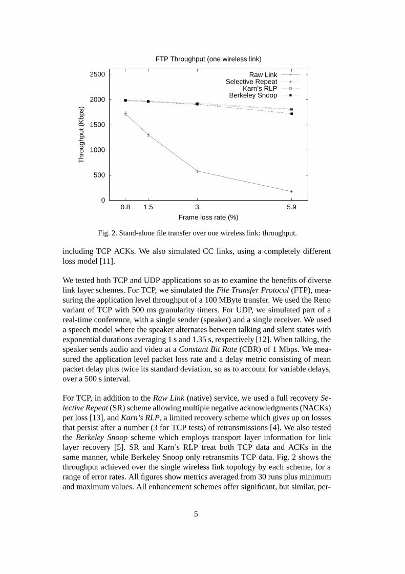
Fig. 2. Stand-alone file transfer over one wireless link: throughput.
including TCP ACKs. We also simulated CC links, using a completely differentloss model [11].
We tested both TCP and UDP applications so as to examine the benefits of diverselink layer schemes. For TCP, we simulated the File Transfer Protocol (FTP), mea-suring the application level throughput of a 100 MByte transfer. We used the Renovariant of TCP with 500 ms granularity timers. For UDP, we simulated part of areal-time conference, with a single sender (speaker) and a single receiver. We useda speech model where the speaker alternates between talking and silent states withexponential durations averaging 1 s and 1.35 s, respectively [12]. When talking, thespeaker sends audio and video at a Constant Bit Rate (CBR) of 1 Mbps. We mea-sured the application level packet loss rate and a delay metric consisting of meanpacket delay plus twice its standard deviation, so as to account for variable delays,over a 500 s interval.
For TCP, in addition to the Raw Link (native) service, we used a full recovery Se-lective Repeat (SR) scheme allowing multiple negative acknowledgments (NACKs)per loss [13], and Karn’s RLP, a limited recovery scheme which gives up on lossesthat persist after a number (3 for TCP tests) of retransmissions [4]. We also testedthe Berkeley Snoop scheme which employs transport layer information for linklayer recovery [5]. SR and Karn’s RLP treat both TCP data and ACKs in thesame manner, while Berkeley Snoop only retransmits TCP data. Fig. 2 shows thethroughput achieved over the single wireless link topology by each scheme, for arange of error rates. All figures show metrics averaged from 30 runs plus minimumand maximum values. All enhancement schemes offer significant, but similar, per-
5

0
500
1000
1500
2000
2500
0.8 1.5 3 5.9
Thr
ough
put (
Kbp
s)
Frame loss rate (%)
FTP Throughput (two wireless links)
Raw LinkSelective Repeat
Karn’s RLPBerkeley Snoop
Fig. 3. Stand-alone file transfer over two wireless links: throughput.
formance gains over Raw Link. While increased loss rates dramatically reduce RawLink performance, the other schemes exhibit only modest performance drops.
In the corresponding two wireless link topology, the throughput results depictedin Fig. 3 reveal the limitations of TCP aware schemes mentioned above. Berke-ley Snoop provides loss recovery only in the direction from the base station to thewireless host. Therefore, wireless losses over one of the two wireless links mustbe recovered from by TCP. In contrast, both SR and Karn’s RLP provide efficientloss recovery regardless of the underlying topology. These schemes perform simi-larly since the low error rates of WLAN links make persistent errors very rare. Asa result, Karn’s RLP effectively provides full recovery. Overall, in our FTP teststhe TCP unaware link layer schemes (SR and Karn’s RLP) improve throughput(compared to Raw Link) by 15–2900%, depending on the topology and native lossrate. Berkeley Snoop depicts topological limitations, which cause it to fail not onlyover multiple wireless link paths, but also with (bi-directional) interactive applica-tions [11].
For UDP, we tested link layer schemes that offer limited recovery in exchange forreduced delays. In addition to Karn’s RLP, we designed an Out of Sequence (OOS)RLP which releases packets to higher layers as they arrive. Karn’s RLP (and SR)release packets in sequence, thus packets received after a loss have to be buffereduntil the lost one is retransmitted. We also studied a block based Forward ErrorCorrection (FEC) scheme producing one parity packet every 12 data packets [11].The parity packet is the logical XOR of the data packets, hence one loss can be tol-erated per (12 packet) block. Fig. 4 shows the residual loss of each scheme against
6

0
0.01
0.02
0.03
0.04
0.05
0.06
0.07
0.08
0.8 1.5 3 5.9
Res
idua
l pac
ket l
oss
prob
abili
ty
Frame loss rate (%)
CBR Loss Rate (one wireless link)
Raw LinkXOR based FEC
Karn’s RLPOut of sequence RLP
Fig. 4. Stand-alone real-time conferencing over a single wireless link: loss.
0
0.01
0.02
0.03
0.04
0.05
0.06
0.8 1.5 3 5.9
Pac
ket d
elay
(se
cond
s)
Frame loss rate (%)
CBR Delay (one wireless link)
Raw LinkXOR based FEC
Karn’s RLPOut of sequence RLP
Fig. 5. Stand-alone real-time conferencing over one wireless link: delay.
the native loss rate, for real-time conferencing in the single wireless link topology.Both RLP schemes dramatically reduce losses, even though their retransmissionlimit is set to 1. The FEC scheme on the other hand depicts gains that do not justifyits error recovery overhead.
7

LinkLayer
Frame Scheduler
MAC
Packet Classifier
Service nService 1
Protocol Port DS
...
Fig. 6. Multi-service link layer architecture.
Fig. 5 shows the delay metrics of each scheme for this scenario. The Raw Linkcurve is flat since no recovery takes place. While both RLP variants perform sim-ilarly at low error rates, as link conditions deteriorate only OOS RLP manages tokeep delay low. In sequence delivery causes many packets to be delayed after ev-ery loss, thus inflating both average delay and its standard deviation. With multiplewireless links, in sequence delivery can cause packets to be repeatedly delayedeven when they are not lost, thus making OOS RLP more attractive. While TCPfavors in sequence delivery, OOS RLP is perfectly adequate for real-time applica-tions that use their own resequencing buffers. For the low delay WLAN links, OOSRLP leads to lower delays than the FEC scheme studied, in which recovery has towait for the parity packet to arrive.
4 Multi-Service Link Layer Architecture
The results presented briefly above show that link layer error recovery dramaticallyimproves Internet application performance over wireless links. Link layer solutionscan be locally deployed and customized for the underlying link, without modifica-tions to the Internet at large. Our results also show however that different schemeswork best for the TCP and UDP applications tested. Most likely, other UDP ap-plications with their widely varying requirements will favor different mechanisms.Therefore, what is needed at the link layer is a multi-protocol scheme. To this end,we have developed a multi-service link layer architecture, which provides multiplelink enhancement services in parallel over a single physical link. Each service fitsthe needs of a generic class of applications, such as TCP based or real-time UDPbased. To simplify service design, the core architecture assigns incoming packets toappropriate services and fairly shares the available bandwidth of the physical link.Therefore, services are isolated and unaware of each other, which allows them tobe easily implemented and then added or removed depending on future needs.
We summarize below the design of our architecture, which was originally intro-
8

TimeStamper
Sorted Heap
SCFQ Frame Scheduler
Rate Table
Virtual T
ime
Fig. 7. Self Clocked Fair Queueing frame scheduler.
duced in [14], while the remainder of the article focuses on its interface with vari-ous Internet Quality of Service approaches. Fig. 6 shows an outline of our scheme.Incoming packets are classified and passed to the most appropriate service, basedon their sending application. A simple classifier may use the protocol field of theIP header to distinguish between TCP and UDP and the port field of the TCP/UDPheaders to determine the application in use. Alternatively, when the DifferentiatedServices (DS) architecture is used for QoS provision at higher layers, the classi-fier may exploit the DS field of the IP header [15], which remains visible evenwith IP security [7]. Packets from unrecognized applications are mapped to the de-fault, best-effort, service. Each service operates in isolation, using retransmissions,FEC, or any other mechanism desired, and keeping its private buffers, counters andtimers. Outgoing frames are passed to a scheduler which tags each frame with a ser-vice number and eventually passes it to the MAC sublayer for transmission. At thereceiver, frames are demultiplexed based on their tags and passed to the appropriateservice, which may eventually release them to higher layers.
Since each service is allowed to arbitrarily inflate its data stream with error recoveryoverhead, we must use a frame scheduler to prevent heavily inflated streams frommonopolizing the physical link. We chose a Self Clocked Fair Queueing (SCFQ)scheduler [16] which can efficiently but strictly enforce the desired bandwidth al-location for each service when the link is loaded. When some services are idle,their bandwidth is shared among the rest in proportion to their original allocations.Fig. 7 gives an outline of the scheduler. The rate table holds the fraction of linkbandwidth allocated to each service. We can set these rates statically to reflect pol-icy decisions, or the classifier may dynamically set them to the fraction of incomingtraffic that it recently allocated to each service, before error recovery takes place.This guarantees that the best-effort service will receive exactly the same bandwidthas without any link layer enhancements, irrespective of the other services on thelink.
Frames awaiting transmission are buffered in service specific queues. A virtualtime variable is maintained which is equal to the time stamp of the last packet
9

transmitted. To determine the time stamp of an incoming packet, we divide its sizeby its service rate, and add the result to the time stamp of the preceding framein its queue. If its queue is empty, we use the current virtual time instead. Whenthe link becomes idle, the frame with the lowest virtual time is dequeued, its timestamp becomes the system’s virtual time, and the frame begins transmission. Thescheduler organizes all non-empty queues in a heap sorted by the time stamp oftheir first frame, thus the next frame to transmit is always found at the top. Theheap is partially re-sorted when a frame is dequeued for transmission, using thenew head of its queue. Empty queues are removed from the heap. They are re-inserted when they receive a new frame, also causing a partial heap re-sort. Thus,each frame requires a simple calculation for its time stamp and log
2n operations
(for n services) to re-sort the heap when the frame leaves (and, possibly, when itenters) the scheduler.
Our multi-service link layer architecture can be incrementally deployed over arbi-trary wireless links, transparently to the rest of the Internet. Additional services canbe provided by inserting new modules and extending the mappings of the packetclassifier, which is reusable over any type of wireless link. Services may be opti-mized for the underlying link, freely selecting the most appropriate mechanismsfor their goals. The scheduler ensures that services will fairly share the link despitetheir variable overheads, without being aware of each other. Service rates may beset statically or calculated dynamically to match classifier decisions, while applica-tions may be mapped to services either heuristically, or, in the presence of higherlayer QoS schemes, intelligently.
5 Multi-Service Link Layer Performance
In order to verify whether our architecture can simultaneously enhance the perfor-mance of diverse applications, we repeated the simulations of Sect. 3 with bothapplications executing in parallel over the same path but using different link layerschemes. Although the scheduler allocated 1 Mbps to the UDP application, the av-erage bandwidth available to FTP was 1.575 Mbps as real-time conferencing wasnot constantly active. Fig. 8 shows FTP throughput in the two wireless link topol-ogy over various schemes (in parentheses, the scheme used for UDP). The curvesare similar to those of Fig. 3, showing that contention with real-time conferencingonly results in reduced FTP bandwidth. UDP application bandwidth is effectivelyprotected by the scheduler which limits even the more persistent SR scheme to itsfair share of the link.
Residual losses for real-time conferencing were the same as in single applicationtests, as error recovery is not influenced by contention. The delay metrics, shown inFig. 9 for the above scenario, were inflated though, an unavoidable effect with ournon-preemptive work-conserving scheduler, which managed however to keep delay
10

0
500
1000
1500
2000
0.8 1.5 3 5.9
Thr
ough
put (
Kbp
s)
Frame loss rate (%)
FTP Throughput (two wireless links)
Raw Link (and Raw Link)Selective Repeat (and OOS RLP)
Karn’s RLP (and OOS RLP)Berkeley Snoop (and OOS RLP)
Fig. 8. File transfer and real-time conferencing over two wireless links: throughput.
at reasonable levels. The reduced delays at higher native loss rates with some TCPschemes were due to deteriorating FTP performance which reduced contention.Karn’s RLP provided a better balance between FTP throughput and real-time con-ferencing delay than the more persistent SR scheme. Overall, the multi service linklayer approach provided similar gains as in single application tests. FTP perfor-mance improved by 11–2425%, depending on the topology and native loss rate,while conferencing delay was kept low as the scheduler prevented TCP from steal-ing UDP bandwidth.
6 Best-effort Service Interface
A critical component of a multi-service link layer is the classifier function thatmaps incoming IP packets to available link services. The lowest standard proto-col layer on the Internet, the network layer, provides a single, best-effort, packetdelivery service. It is assumed that higher layer protocols can extend this serviceto satisfy any additional application requirements. Our simulations show howeverthat multiple link layer services are actually needed to enhance Internet applicationperformance over wireless links. Since IP and higher layer protocols are not awareof multi-service links though, they cannot map themselves their requirements to theavailable link services. To remain compatible with the existing Internet infrastruc-ture, our architecture should perform this mapping transparently, without changingthe interface between the link and network layers. Due to the scale and constantevolution of the Internet, such changes take very long to propagate everywhere.
11

0
0.05
0.1
0.15
0.2
0.25
0.3
0.35
0.8 1.5 3 5.9
Pac
ket d
elay
(se
cond
s)
Frame loss rate (%)
CBR Delay (two wireless links)
Raw Link (and Raw Link)OOS RLP (and Selective Repeat)
OOS RLP (and Karn’s RLP)OOS RLP (and Berkeley Snoop)
Fig. 9. Real-time conferencing and file transfer over two wireless links: delay.
TOS
Lookup Table
Hashing Function
Packet Classifier
Protocol
Source Port (TCP/UDP) Destination Port (TCP/UDP)
IPv4 Packet Mask
Service Measurements
Fig. 10. Heuristic packet classifier.
Performance should always be at least as good as with a single service, i.e. appli-cations should never be mapped to services that degrade their performance and en-hancing the performance of some applications should not degrade the performanceof others.
By meeting these requirements, we allow services to be introduced gradually toenhance the performance of some applications, without affecting the rest. Our link
12
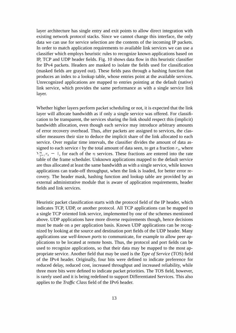
layer architecture has single entry and exit points to allow direct integration withexisting network protocol stacks. Since we cannot change this interface, the onlydata we can use for service selection are the contents of the incoming IP packets.In order to match application requirements to available link services we can use aclassifier which employs heuristic rules to recognize known applications based onIP, TCP and UDP header fields. Fig. 10 shows data flow in this heuristic classifierfor IPv4 packets. Headers are masked to isolate the fields used for classification(masked fields are grayed out). These fields pass through a hashing function thatproduces an index to a lookup table, whose entries point at the available services.Unrecognized applications are mapped to entries pointing at the default (native)link service, which provides the same performance as with a single service linklayer.
Whether higher layers perform packet scheduling or not, it is expected that the linklayer will allocate bandwidth as if only a single service was offered. For classifi-cation to be transparent, the services sharing the link should respect this (implicit)bandwidth allocation, even though each service may introduce arbitrary amountsof error recovery overhead. Thus, after packets are assigned to services, the clas-sifier measures their size to deduce the implicit share of the link allocated to eachservice. Over regular time intervals, the classifier divides the amount of data as-signed to each service i by the total amount of data seen, to get a fraction ri, where�n
i=1ri = 1, for each of the n services. These fractions are entered into the rate
table of the frame scheduler. Unknown applications mapped to the default serviceare thus allocated at least the same bandwidth as with a single service, while knownapplications can trade-off throughput, when the link is loaded, for better error re-covery. The header mask, hashing function and lookup table are provided by anexternal administrative module that is aware of application requirements, headerfields and link services.
Heuristic packet classification starts with the protocol field of the IP header, whichindicates TCP, UDP, or another protocol. All TCP applications can be mapped toa single TCP oriented link service, implemented by one of the schemes mentionedabove. UDP applications have more diverse requirements though, hence decisionsmust be made on a per application basis. Known UDP applications can be recog-nized by looking at the source and destination port fields of the UDP header. Manyapplications use well-known ports to communicate, for example to allow peer ap-plications to be located at remote hosts. Thus, the protocol and port fields can beused to recognize applications, so that their data may be mapped to the most ap-propriate service. Another field that may be used is the Type of Service (TOS) fieldof the IPv4 header. Originally, four bits were defined to indicate preference forreduced delay, reduced cost, increased throughput and increased reliability, whilethree more bits were defined to indicate packet priorities. The TOS field, however,is rarely used and it is being redefined to support Differentiated Services. This alsoapplies to the Traffic Class field of the IPv6 header.
13

A significant drawback of heuristic classifiers is the considerable effort requiredto construct them. Applications must be manually matched to the services avail-able over each type of wireless link whenever new applications or services areadded. Many applications will not be recognized, not only due to the large numberof existing and future applications, but also because many applications do not usewell-known ports. Although some higher layer QoS schemes combine the transportprotocol, source/destination port and host address fields to classify packets [17],setting up and maintaining state for all these combinations requires end-to-end sig-naling and considerable storage, both of which are not available at the link layer.Another important problem with heuristic classifiers is that IP security mechanismsencrypt the source/destination ports of TCP and UDP headers and replace the valueof the protocol field with the identifier of the IP security protocol [7]. This leavesonly the TOS field visible, which is currently inadequate to describe applicationrequirements.
7 Differentiated Services Interface
The single best-effort service provided by IP is becoming inadequate as real-timeapplications migrate from the circuit-switched telephone network with its explicitdelay guarantees to the packet-switched Internet. For these applications to exploitthe reduced costs promised by statistical multiplexing, some type of performanceguarantees must be introduced into the Internet. Users would presumably pay morefor better Internet service, if it was still cheaper to use the Internet rather than acircuit-switched network for the same task. The main issue for Internet QoS isgenerally considered to be congestion control. Applications may not be able to getthe throughput they need due to contention for link resources and their end-to-end delay may increase due to queueing delays at congested routers. When routerqueues overflow, data loss also occurs. UDP applications have to deal with theselosses themselves, while TCP applications face additional delays during end-to-endrecovery.
One scheme for Internet QoS provision is the Integrated Services architecture [18],which has been criticized in two ways. First, it must be widely deployed over theInternet to be useful, since its guarantees rely on actions at every router on a path.Second, it mandates resource reservations on a per flow basis, where a flow is de-fined as a data stream between two user processes with fixed QoS requirements.Since a huge number of flows exists, the global scalability of any QoS schemebased on per flow state is doubtful. In IPv6 a 20 bit flow label is defined in the IPheader to identify flows between two hosts, while host addresses are expanded to128 bits. The only solution to this scalability problem is to aggregate flow state, butit is unclear how to do so.
An alternative scheme that attempts to avoid these limitations is the Differentiated
14

Services architecture [15], in which flows are aggregated into a few classes, eitherwhen entering the network, or when crossing network domains. At these pointsonly, flows may be rate limited, shaped or marked to conform to specific trafficprofiles. These are negotiated between users and network providers or betweenneighboring domains. Within a domain, routers only need to select a Per-Hop Be-havior (PHB) for each packet, based on its class, denoted by the 8-bit Differenti-ated Services (DS) field of the IP header. This subsumes both the IPv4 TOS andthe IPv6 Traffic Class fields. State aggregation into a few classes means that thisscheme scales well, but the guarantees that may be provided are not as fine grainedas with Integrated Services.
This architecture intentionally leaves the definition of PHBs open, to allow exper-imentation with different approaches. For example, the expedited forwarding PHBprovides a minimum amount of bandwidth at each router, for traffic that was ratelimited when entering the network or the domain so as not to exceed this band-width. This PHB provides low delay and loss by eliminating congestion for theclass, offering a virtual leased line service. As another example, the assured for-warding PHB group defines a number of service classes, with each one allocateda specific share of the bandwidth. Within each class, packets may have multiplelevels of drop preference. Besides scheduling so as to satisfy the bandwidth re-quirements of each class, when a class is congested routers should first drop thepackets with highest drop preference. Flows are marked with higher drop prefer-ence levels when they exceed the traffic profile of their class, rather than being ratelimited. Both PHBs may be implemented by many scheduling mechanisms andqueue management schemes.
The services provided by this architecture depend on the available PHBs and aremeant to provide generic QoS levels, not application specific guarantees, hencethe mapping of traffic classes and not flows to PHBs. Only network entry pointsare aware of both application requirements and PHB semantics so as to performflow aggregation. Similarly, only domain entry points are aware of the semantics ofPHBs available in their neighboring domains so as to perform appropriate transla-tions. Traffic policing, shaping and marking, is also only performed at those points.For neighboring domains, traffic profiles should be relatively static as they repre-sent large traffic aggregates, while at network entry points they could be frequentlymodified by the user. This is far more economical than the flow specific signalingof Integrated Services.
Differentiated Services and multi-service link layers solve orthogonal but comple-mentary problems. Differentiated Services are concerned with congestion and itsimpact on throughput, delay and loss. The services offered are based on link in-dependent PHBs, provided by IP level packet scheduling and queue managementmechanisms. Multi-service link layers are concerned with recovery from link er-rors, customized to each type of application. The error recovery mechanisms usedare link dependent and local, thus they cannot be standardized into link indepen-
15

Traffic Class
Hashing Function
Lookup Table
Packet Classifier
IPv6 Packet Mask
Fig. 11. Differentiated Services packet classifier.
dent PHBs. The frame scheduling provided only protects services from each otherby mirroring higher layer allocations, it does not offer end-to-end guarantees. Byonly providing Differentiated Services over wireless links we can offer to applica-tions a nominal IP level QoS, but their actual performance will be limited by linklosses. Even if we reserve wireless link bandwidth for a TCP traffic class for ex-ample, only a small fraction of it will be used due to losses and inefficient TCP(end-to-end) error recovery. Multi-service link layers provide adequate recovery tofully utilize wireless links, but they also need higher layer guidance to allocate linkbandwidth.
These two architectures are excellent complements to each other. DifferentiatedServices provide congestion control, using packet scheduling and queue manage-ment, while multi-service link layers add application dependent error control, re-specting higher layer scheduling despite the introduction of recovery overhead.They both offer a few services at each node (PHBs or link mechanisms) for ag-gregated traffic classes with common requirements. They can be combined by ex-tending the DS field to also specify the error requirements of each traffic class.For example, a traffic class with a reserved amount of bandwidth could be subdi-vided into two subclasses with different error recovery requirements by using onemore bit of the DS field. Each subclass would be mapped to an appropriate linklayer service. DS bits are set when flows are aggregated into classes. Applicationscould indicate their requirements when injecting their traffic into the network, withboundary routers translating them to local equivalents when required. The result isa simplified multi-service classifier, shown in Fig. 11 for IPv6 packets. The DS fieldis isolated via a header mask, and then a hashing function plus a lookup table mapit to an appropriate service. The same procedure can be used with IPv4 headers,where the DS field is the original TOS field instead of the IPv6 Traffic Class field.
16

Such a classifier does not rely on multiple header fields and complex rules to deter-mine application requirements. A single field is used with well-defined semantics.New applications may be mapped to existing classes if their requirements are sim-ilar to those of previously mapped applications. More importantly, the DS field isnot obscured by IP security mechanisms, it is visible even in encrypted packets.Since the Differentiated Services module performs scheduling and queue manage-ment, traffic entering the multi-service link layer already obeys the required band-width allocations. For example, two TCP traffic subclasses belonging to separateDS classes may be rate limited in different ways at the IP level. At the link layer,however, they are already shaped as needed, hence they can share the same serviceand frame scheduler queue without introducing congestion. Thus, regardless of thenumber of DS traffic classes used, the multi-service link layer must only maintain asingle instance of each service. The service rates can be set in two ways. If the sub-classes of each DS traffic class have separate bandwidth allocations at the IP level,then the bandwidth for all subclasses mapped to the same link service is added toset its service rate. If subclasses share a common bandwidth pool within each class,then a service measurements module can be inserted after the lookup table, as inFig. 10, to automatically determine service rates.
8 Advanced Quality of Service Interface
The performance of the various services available at each wireless link can varywidely. Different links may favor different error recovery schemes, with the per-formance of each scheme varying over time due to unpredictable environmentalconditions. If a characterization of the end-to-end performance of a network pathis provided, applications can verify that a given end-to-end service is suitable fortheir needs [19]. In addition, when path characteristics change significantly, up-dated characterizations enable adaptive higher layers to modify their policies. Hi-erarchical cellular systems for example are composed of multiple overlaid cellularsystems: satellites cover the whole globe, cellular systems cover populated areas,and indoor WLANs cover buildings. In these systems, in addition to horizontalhandoffs between adjacent cells of the same system, the user can perform verti-cal handoffs between different systems. Horizontal handoffs may cause changes toerror behavior and traffic load, while vertical handoffs may alter all wireless linkcharacteristics. To describe the services offered over network paths that are so di-verse, we must dynamically discover what is provided at each link. This can beachieved if each service dynamically characterizes its performance with a set ofstandardized metrics. Dynamic characterization means that performance may beevaluated as often as needed, while metric standardization means that higher layerswill be able to assess the performance of arbitrary services without any knowledgeof the link layer mechanisms employed. This would enable end-to-end QoS mod-ules to compose local link metrics into end-to-end path metrics.
17

Table 1Service characterization metrics.
Name Symbol Definition
Goodput gi
higher layer data transmitted
link layer data transmitted
Loss li
higher layer data lost
higher layer data transmitted
Delay di Average packet delivery delay
Effective Goodput ei = gi � (1� li)
higher layer data received
link layer data transmitted
We have defined three link independent metrics, reflecting the possible trade-offsavailable to each error recovery scheme: goodput, loss and delay. Metrics are cal-culated dynamically over an implementation dependent interval. Reported metricsmay be smoothed by using a weighted average of the latest calculated value andthe previous reported value, similar to TCP round trip delay estimates. Goodput(gi, for service i) is the ratio of higher layer data transmitted during the measure-ment interval to link layer data transmitted, including all overhead. The amount ofhigher layer data transmitted may differ from the amount received due to residuallosses. Goodput can be calculated at the sender without any receiver feedback. Loss(li) is the ratio of higher layer data lost to higher layer data transmitted (lost plusreceived). Loss is calculated by the receiver based on the sequence of data releasedto higher layers. It depicts the residual loss rate after link layer error recovery. Itcan be greater than zero for limited recovery schemes. Delay (di) is the one wayaverage delay (in seconds) for higher layer packets. Delay can be estimated at thereceiver based on knowledge of the implemented recovery scheme and wirelesslink characteristics. Retransmission schemes could add one round trip delay esti-mate for each retransmission to their one way delay estimate. A FEC scheme couldinstead add the interval between the loss of a recovered frame and its reconstructionfrom parity data to its one way delay estimate.
The delay metric only denotes the error recovery delay of a service, since there isno congestion inside the link layer. It can be added to IP level queueing delay togive the total delay for each node, which can be used to estimate end-to-end delaysincorporating both congestion control and wireless error recovery. Delay sensitivetraffic subclasses should choose the lowest delay service whose residual loss fallswithin their tolerance limits. Goodput can be combined with loss to get EffectiveGoodput (ei), defined as ei = gi � (1� li), or, the ratio of higher layer data receivedto link layer data transmitted. Essentially, ei shows how much of the bandwidthallocated to a service is used by the data actually received, after subtracting errorrecovery overhead and residual losses. If the link bandwidth is B and service i
is allocated a service rate ri in the scheduler, then its throughput is B � ri � ei.This may be used to estimate the throughput for each service given a set of service
18

Adaptive Mobility Aware Transport Transport Layer
Network Layer
Standard Measurements and Signals
Hardware/Firmware Physical Layer
Adaptive Mobility Aware Application Application Layer
Application Metrics
Protocol Metrics
Link Layer
Service Metrics
Link Specific Metrics
CBQ RSVP
Vertical Handoffs
Horizontal Handoffs
Mobility Hint Signals
Link Specific Signals
Mobile IP
Fig. 12. Propagation of service measurement and mobility feedback.
rates, or to calculate the service rate needed to achieve a target throughput for aparticular service. The reason for using goodput instead of throughput for servicecharacterization is exactly that goodput, unlike throughput, can be used to predictservice behavior with different rate allocations. All these metrics are summarizedin Table 1.
These metrics may be used at multiple layers to serve different needs, as shown inFig. 12. The physical layer provides hardware dependent information, such as thefixed one way delay, that may be used by link layer services to provide their linkindependent gi, li and di metrics. At the network layer, scheduling mechanismssuch as Class Based Queueing (CBQ) may use those metrics to set the bandwidthallocations for each service. End-to-end QoS schemes may use the Resource ReSer-Vation Protocol (RSVP) to gather information about node services so as to estimateend-to-end path characteristics. These can in turn be used by both transport proto-cols and applications to adapt their operation to prevailing conditions. For example,TCP may limit its congestion window to respect available bandwidth limitations,or, video conferencing applications may select encoding schemes that can deal withthe residual loss rate of the path. Metrics can be refined at each layer, as in the net-work layer where local link metrics are used to compose end-to-end path metrics.
To assist higher layers in dealing with mobility, we can extend this interface to pro-vide mobility hints to interested parties via upcalls, as shown in Fig. 12. The linklayer can combine hardware signals with its own state to detect events like connec-tions and disconnections. If a handoff is taking place, higher layers will receive onedisconnection and one connection upcall from different links. These link indepen-
19

dent upcalls can be used by the IP mobility extensions to allow fast detection ofhandoffs, instead of relying on periodic network layer probes [20]. Higher layersmay be notified by the network layer of horizontal and vertical handoffs via furtherupcalls. TCP may be notified of pending horizontal handoffs to temporarily freezeits timers and avoid timeouts during disconnection intervals. A video conferenc-ing application may be notified of vertical handoffs so as to change the encodingscheme used to a higher or lower resolution one, depending on available bandwidth.The characteristics of the new path can be discovered by using end-to-end QoS pro-visioning mechanisms to query the metrics exported by the new wireless link of thepath.
Our QoS interface was designed to fit the needs of One Pass With Advertising(OPWA) [19] resource reservation mechanisms. One pass schemes cannot specify adesired service in advance as they do not know what is available on a path [17], thusthe resources reserved may provide inadequate service. Two pass schemes specifya service in advance but make very restrictive reservations on the first pass, relaxingthem on a second pass [21]. Such reservations may fail due to tight restrictions onthe first pass. In an OPWA scheme, an advertising pass is first made to discoverthe services available on the path, and then a reservation pass actually reserves theresources needed for the selected service. Our interface allows OPWA schemes todiscover the throughput, delay and loss restrictions imposed by wireless links, bylooking at local service metrics. After that information is gathered, applicationsmay choose a service, and the reservation pass can set up appropriate state so asto provide it. Mobility hints notify higher layers that they should revise their pathcharacterizations after handoffs, thus fitting the needs of adaptive mobility awareapplications which can adapt their operation based on resource availability.
A related proposal has been made in the context of IP mobility: a router could notifyhosts communicating with a wireless host of new link characteristics after a hand-off [22]. This approach however does not support link characterization betweenhandoffs or multiple services. Another related proposal specifies an adaptation in-terface for mobility aware applications that notifies applications when availablebandwidth deviates from a given range [23]. An application supporting multipleencodings of its data would select a bandwidth range for each, switching encod-ings whenever the available bandwidth moved into another range. This interface isnot appropriate for the link layer, as it requires end-to-end signaling and per ap-plication state, but it can be easily implemented using our mobility hints. A QoSmanagement module at each host would accept bandwidth range requests from lo-cal applications. Instead of monitoring the link, it would only check its data baseafter receiving a mobility hint, in turn notifying the applications whose ranges hadchanged.
20

9 Conclusions
While extending the Internet over wireless links is straightforward, application per-formance over wireless links using the traditional Internet protocols has been disap-pointing due to channel impairments and adverse interactions between protocol lay-ers. Different applications favor different error control approaches, thus we devel-oped a link layer architecture that provides multiple services simultaneously overa single link, allowing the most appropriate link service to be used by each trafficclass. Our approach is easy to optimize for each underlying wireless link and effi-cient to operate. It can be locally deployed, transparently to the rest of the Internet,and it is easy to extend to address future requirements. It can be incorporated intothe Internet QoS architecture in three stages. First, in the current best-effort onlyInternet, we can employ heuristic classifiers to select services provided over indi-vidual multi-service links to enhance the performance of recognized applications.Second, in the context of the Differentiated Services architecture, which focuseson end-to-end congestion control, multi-service link layers can provide applicationdependent error control, respecting higher layer scheduling decisions despite theintroduction of error recovery overhead. Finally, multi-service link layers can sup-port an advanced QoS application interface, offering dynamic end-to-end servicediscovery and synthesis.
Acknowledgements
The authors gratefully acknowledge the support of the General Secretariat of Re-search and Technology of Greece under grant 99ED193.
References
[1] G. Xylomenos, G. C. Polyzos, Quality of Service issues in multi-service wirelessInternet links, in: Proc. International Workshop QoS-IP 2001, Lecture Notes inComputer Science, vol. 1989, M. Ajmone Marsan, A. Bianco, (Eds.), Springer, Berlin,2001, pp. 347–365.
[2] W. Stevens, TCP slow start, congestion avoidance, fast retransmit, and fast recoveryalgorithms, RFC 2001 (January 1997).
[3] G. T. Nguyen, R. H. Katz, B. Noble, M. Satyanarayanan, A trace-based approach formodeling wireless channel behavior, in: Proc. of the Winter Simulation Conference,1996, pp. 597–604.
[4] P. Karn, The Qualcomm CDMA digital cellular system, in: Proc. of the USENIXMobile and Location-Independent Computing Symposium, 1993, pp. 35–39.
21

[5] H. Balakrishnan, V. N. Padmanabhan, S. Seshan, R. H. Katz, A comparison ofmechanisms for improving TCP performance over wireless links, in: Proc. of the ACMSIGCOMM ’96, 1996, pp. 256–267.
[6] B. R. Badrinath, A. Bakre, T. Imielinski, R. Marantz, Handling mobile clients: Acase for indirect interaction, in: Proc. of the 4th Workshop on Workstation OperatingSystems, 1993, pp. 91–97.
[7] S. Kent, R. Atkinson, IP encapsulating security payload (ESP), RFC 2406 (November1998).
[8] A. DeSimone, M. C. Chuah, O. Yue, Throughput performance of transport-layerprotocols over wireless LANs, in: Proc. of the IEEE GLOBECOM ’93, 1993, pp.542–549.
[9] G. Xylomenos, G. C. Polyzos, Internet protocol performance over networks withwireless links, IEEE Network 13 (1999) 55–63.
[10] UCB/LBNL/VINT Network Simulator - ns (version 2), available at http://www-mash.cs.berkeley.edu/ns.
[11] G. Xylomenos, Multi Service Link Layers: An approach for enhancing Internetperformance over wireless links, Ph.D. thesis, University of California, San Diego,available at http://www-cse.ucsd.edu/groups/csl/pubs/phd.html (1999).
[12] S. Nanda, D. J. Goodman, U. Timor, Performance of PRMA: a packet voice protocolfor cellular systems, IEEE Transactions on Vehicular Technology 40 (1991) 584–598.
[13] P. T. Brady, Evaluation of multireject, selective reject, and other protocolenhancements, IEEE Transactions on Communications 35 (1987) 659–666.
[14] G. Xylomenos, G. Polyzos, Link Layer Support for Quality of Service on WirelessInternet Links, IEEE Personal Communications 6 (1999) 52–60.
[15] S. Blake, D. Black, M. Carlson, E. Davies, Z. Wang, W. Weiss, An architecture forDifferentiated Services, RFC 2475 (December 1998).
[16] S. Golestani, A self-clocked fair queueing scheme for broadband applications, in:Proc. of the IEEE INFOCOM ’94, 1994, pp. 636–646.
[17] L. Zhang, S. Deering, D. Estrin, S. Shenker, D. Zappala, RSVP: A new resourcereservation protocol, IEEE Network 7 (1993) 8–18.
[18] D. D. Clark, S. Shenker, L. Zhang, Supporting real-time applications in an integratedservices packet network: architecture and mechanism, in: Proceedings of the ACMSIGCOMM ’96, 1996, pp. 243–254.
[19] S. Shenker, L. Breslau, Two issues in reservation establishment, in: Proceedings of theACM SIGCOMM ’95, 1995, pp. 14–26.
[20] C. Perkins, IP mobility support, RFC 2002 (October 1996).
[21] D. Ferrari, D. C. Verma, A scheme for real-time channel establishment in wide-areanetworks, IEEE Journal on Selected Areas in Communications 8 (1990) 368–379.
22

[22] D. B. Johnson, D. A. Maltz, Protocols for adaptive wireless and mobile networking,IEEE Personal Communications 3 (1996) 34–42.
[23] B. D. Noble, M. Price, M. Satyanarayanan, A programming interface for application-aware adaptation in mobile computing, in: Proceedings of the 2nd USENIXSymposium on Mobile and Location-Independent Computing, 1995, pp. 57–66.
23