Quality of Service (QoS) - D-Link Series/images/pdf/7... · Quality of Service (QoS) Basic Settings...
20
DGS-1510 Series Gigabit Ethernet SmartPro Switch Web UI Reference Guide 145 7. Quality of Service (QoS) Basic Settings Advanced Settings Basic Settings Port Default CoS This window is used to view and configure the port’s default CoS settings. To view the following window, click QoS > Basic Settings > Port Default CoS, as shown below: Figure 7-1 Port Default CoS window The fields that can be configured are described below: Parameter Description Unit Select the switch unit that will be used for this configuration here. From Port / To Port Select the appropriate port range used for the configuration here. Default CoS Select the default CoS option for the port(s) specified here. Options to choose from are 0 to 7. Tick the Override check box to override the CoS of the packets. The default CoS will be applied to all incoming packets, tagged or untagged, received by the port. Select the None option to specify that the CoS of the packets will be the packet’s CoS if the packets are tagged, and will be the port default CoS if the packet is untagged. Click the Apply button to accept the changes made.
Transcript of Quality of Service (QoS) - D-Link Series/images/pdf/7... · Quality of Service (QoS) Basic Settings...
DGS-1510 Series Gigabit Ethernet SmartPro Switch Web UI Reference Guide
145
7. Quality of Service (QoS)
Basic Settings Advanced Settings
Basic Settings
Port Default CoS
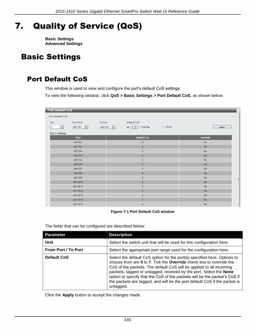
This window is used to view and configure the port’s default CoS settings.
To view the following window, click QoS > Basic Settings > Port Default CoS, as shown below:
Figure 7-1 Port Default CoS window
The fields that can be configured are described below:
Parameter Description
Unit Select the switch unit that will be used for this configuration here.
From Port / To Port Select the appropriate port range used for the configuration here.
Default CoS Select the default CoS option for the port(s) specified here. Options to choose from are 0 to 7. Tick the Override check box to override the
CoS of the packets. The default CoS will be applied to all incoming packets, tagged or untagged, received by the port. Select the None
option to specify that the CoS of the packets will be the packet’s CoS if the packets are tagged, and will be the port default CoS if the packet is untagged.
Click the Apply button to accept the changes made.

DGS-1510 Series Gigabit Ethernet SmartPro Switch Web UI Reference Guide
146
Port Scheduler Method
This window is used to view and configure the port scheduler method settings.
To view the following window, click QoS > Basic Settings > Port Scheduler Method, as shown below:
Figure 7-2 Port Scheduler Method window
The fields that can be configured are described below:
Parameter Description
Unit Select the switch unit that will be used for this configuration here.
From Port / To Port Select the appropriate port range used for the configuration here.
Scheduler Method Select the scheduler method that will be applied to the specified port(s). Options to choose from are Strict Priority (SP), Round-Robin (RR), Weighted Round-Robin (WRR), and Weighted Deficit Round-Robin (WDRR). By default, the output queue scheduling algorithm is WRR.
WDRR operates by serving an accumulated set of backlogged credits
in the transmit queue in a round robin order. Initially, each queue sets its credit counter to a configurable quantum value. Every time a packet from a CoS queue is sent, the size of the packet is subtracted from the corresponding credit counter and the service right is turned over to the next lower CoS queue. When the credit counter drops below 0, the queue is no longer serviced until its credits are replenished. When the credit counters of all CoS queues reaches 0, the credit counters will be replenished at that time. All packets are serviced until their credit counter is zero or negative and the last packet is transmitted completely. When this condition happens, the credits are replenished. When the credits are replenished, a quantum of credits are added to each CoS queue credit counter. The quantum for each CoS queue may be different based on the user configuration.
To set a CoS queue in the SP mode, any higher priority CoS queue
must also be in the strict priority mode.
WRR operates by transmitting permitted packets into the transmit
queue in a round robin order. Initially, each queue sets its weight to a

DGS-1510 Series Gigabit Ethernet SmartPro Switch Web UI Reference Guide
147
configurable weighting. Every time a packet from a higher priority CoS queue is sent, the corresponding weight is subtracted by 1 and the packet in the next lower CoS queue will be serviced. When the weight of a CoS queue reaches zero, the queue will not be serviced until its weight is replenished. When weights of all CoS queues reach 0, the weights get replenished at a time.
Click the Apply button to accept the changes made.
Queue Settings
This window is used to view and configure the queue settings.
To view the following window, click QoS > Basic Settings > Queue Settings, as shown below:
Figure 7-3 Queue Settings window
The fields that can be configured are described below:
Parameter Description
Unit Select the switch unit that will be used for this configuration here.
From Port / To Port Select the appropriate port range used for the configuration here.
Queue ID Enter the queue ID value here. This value must be between 0 and 7.
WRR Weight Enter the WRR weight value here. This value must be between 0 and 127. To satisfy the behavior requirements of Expedited Forwarding (EF), the highest queue is always selected by the Per-hop Behavior (PHB) EF and the schedule mode of this queue should be strict priority

DGS-1510 Series Gigabit Ethernet SmartPro Switch Web UI Reference Guide
148
scheduling. So the weight of the last queue should be zero while the Differentiate Service is supported.
WDRR Quantum Enter the WDRR quantum value here. This value must be between 0 and 127.
Click the Apply button to accept the changes made.
CoS to Queue Mapping
This window is used to view and configure the CoS-to-Queue mapping settings.
To view the following window, click QoS > Basic Settings > CoS to Queue Mapping, as shown below:
Figure 7-4 CoS to Queue Mapping window
The fields that can be configured are described below:
Parameter Description
Queue ID Select the queue ID that will be mapped to the corresponding CoS value. Options to choose from are 0 to 7.
Click the Apply button to accept the changes made.
Port Rate Limiting
This window is used to view and configure the port rate limiting settings.
To view the following window, click QoS > Basic Settings > Port Rate Limiting, as shown below:

DGS-1510 Series Gigabit Ethernet SmartPro Switch Web UI Reference Guide
149
Figure 7-5 Port Rate Limiting window
The fields that can be configured are described below:
Parameter Description
Unit Select the switch unit that will be used for this configuration here.
From Port / To Port Select the appropriate port range used for the configuration here.
Direction Select the direction option here. Options to choose from are Input and Output. When Input is selected, the rate limit for ingress packets is configured. When Output is selected, the rate limit for egress packets
is configured.
Rate Limit Select and enter the rate limit value here.
When Bandwidth is selected, enter the input/output bandwidth value
used in the space provided. This value must be between 64 and 10000000 kbps. Also, enter the Burst Size value in the space
provided. This value must be between 0 and 128000 kilobytes.
When Percent is selected, enter the input/output bandwidth
percentage value used in the space provided. This value must be between 1 and 100 percent (%). Also, enter the Burst Size value in
the space provided. This value must be between 0 and 128000 kilobytes.
Select the None option to remove the rate limit on the specified port(s).
The specified limitation cannot exceed the maximum speed of the specified interface. For the ingress bandwidth limitation, the ingress can trigger a pause frame or a flow control frame when the received traffic exceeds the limitation.
Click the Apply button to accept the changes made.
Queue Rate Limiting
This window is used to view and configure the queue rate limiting settings.

DGS-1510 Series Gigabit Ethernet SmartPro Switch Web UI Reference Guide
150
To view the following window, click QoS > Basic Settings > Queue Rate Limiting, as shown below:
Figure 7-6 Queue Rate Limiting window
The fields that can be configured are described below:
Parameter Description
Unit Select the switch unit that will be used for this configuration here.
From Port / To Port Select the appropriate port range used for the configuration here.
Queue ID Select the queue ID that will be configured here. Options to choose from are 0 to 7.
Rate Limit Select and enter the queue rate limit settings here.
When the Min Bandwidth option is selected, enter the minimum
bandwidth rate limit value in the space provided. This value must be between 64 and 10000000 kbps. Also enter the maximum bandwidth (Max Bandwidth) rate limit in the space provided. This value must be
between 64 and 10000000 kbps.
When the minimal bandwidth is configured, the packet transmitted from the queue can be guaranteed. When the maximum bandwidth is configured, packets transmitted from the queue cannot exceed the maximum bandwidth even if the bandwidth is available.
When configuring the minimal bandwidth, the aggregate of the configured minimum bandwidth must be less than 75 percent of the interface bandwidth to make sure the configured minimal bandwidth can be guaranteed. It is not necessary to set the minimum guaranteed bandwidth for the highest strict priority queue. This is because the traffic in this queue will be serviced first if the minimal bandwidth of all queues is satisfied.
The configuration of this command can only be attached to a physical port but not a port-channel. That is the minimum guaranteed bandwidth of one CoS cannot be used across physical ports.

DGS-1510 Series Gigabit Ethernet SmartPro Switch Web UI Reference Guide
151
When the Min Percent option is selected, enter the minimum
bandwidth percentage value in the space provided. This value must be between 1 and 100 percent (%). Also enter the maximum percentage value (Max Percent) in the space provided. This value must be between 1 and 100 percent (%).
Click the Apply button to accept the changes made.
Advanced Settings
DSCP Mutation Map
This window is used to view and configure the Differentiated Services Code Point (DSCP) mutation map settings. When a packet is received by an interface, based on a DSCP mutation map, the incoming DSCP can be mutated to another DSCP immediately before any QoS operations. The DSCP mutation is helpful to integrate domains with different DSCP assignments. The DSCP-CoS map and DSCP-color map will still be based on the packet’s original DSCP. All the subsequent operations will base on the mutated DSCP.
To view the following window, click QoS > Advanced Settings > DSCP Mutation Map, as shown below:
Figure 7-7 DSCP Mutation Map window
The fields that can be configured are described below:
Parameter Description
Mutation Name Enter the DSCP mutation map name here. This name can be up to 32 characters long.
Input DSCP List Enter the input DSCP list value here. This value must be between 0 and 63.
Output DSCP Enter the output DSCP value here. This value must be between 0 and 63.
Click the Apply button to accept the changes made.
Click the Delete button to remove the specific entry.

DGS-1510 Series Gigabit Ethernet SmartPro Switch Web UI Reference Guide
152
Port Trust State and Mutation Binding
This window is used to view and configure port trust state and mutation binding settings.
To view the following window, click QoS > Advanced Settings > Port Trust State and Mutation Binding, as shown below:
Figure 7-8 Port Trust State and Mutation Binding window
The fields that can be configured are described below:
Parameter Description
Unit Select the switch unit that will be used for this configuration here.
From Port / To Port Select the appropriate port range used for the configuration here.
Trust State Select the port trust state option here. Options to choose from are CoS and DSCP.
DSCP Mutation Map Select and enter the DSCP mutation map name used here. This name can be up to 32 characters long. Select the None option to not allocate
a DSCP mutation map to the port(s).
Click the Apply button to accept the changes made.
DSCP CoS Mapping
This window is used to view and configure the DSCP CoS mapping settings.
To view the following window, click QoS > Advanced Settings > DSCP CoS Mapping, as shown below:

DGS-1510 Series Gigabit Ethernet SmartPro Switch Web UI Reference Guide
153
Figure 7-9 DSCP CoS Mapping window
The fields that can be configured are described below:
Parameter Description
Unit Select the switch unit that will be used for this configuration here.
From Port / To Port Select the appropriate port range used for the configuration here.
CoS Select the CoS value. Options to choose from are 0 to 7.
DSCP List Enter the DSCP list value to map to the CoS value here. This value must be between 0 and 63.
Click the Apply button to accept the changes made.
CoS Color Mapping
This window is used to view and configure the CoS color mapping settings.
To view the following window, click QoS > Advanced Settings > CoS Color Mapping, as shown below:

DGS-1510 Series Gigabit Ethernet SmartPro Switch Web UI Reference Guide
154
Figure 7-10 CoS Color Mapping window
The fields that can be configured are described below:
Parameter Description
Unit Select the switch unit that will be used for this configuration here.
From Port / To Port Select the appropriate port range used for the configuration here.
CoS List Enter the CoS value that will be mapped to the color. This value must be between 0 and 7.
Color Select the color option. Options to choose from are Green, Yellow, and Red.
Click the Apply button to accept the changes made.
DSCP Color Mapping
This window is used to view and configure the DSCP color mapping settings.
To view the following window, click QoS > Advanced Settings > DSCP Color Mapping, as shown below:

DGS-1510 Series Gigabit Ethernet SmartPro Switch Web UI Reference Guide
155
Figure 7-11 DSCP Color Mapping window
The fields that can be configured are described below:
Parameter Description
Unit Select the switch unit that will be used for this configuration here.
From Port / To Port Select the appropriate port range used for the configuration here.
DSCP List Enter the DSCP list value here that will be mapped to a color. This value must be between 0 and 63.
Color Select the color option that will be mapped to the DSCP value. Options to choose from are Green, Yellow, and Red.
Click the Apply button to accept the changes made.
Class Map
This window is used to view and configure the class map settings.
To view the following window, click QoS > Advanced Settings > Class Map, as shown below:
DGS-1510 Series Gigabit Ethernet SmartPro Switch Web UI Reference Guide
156
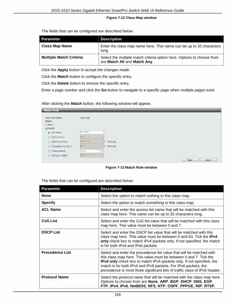
Figure 7-12 Class Map window
The fields that can be configured are described below:
Parameter Description
Class Map Name Enter the class map name here. This name can be up to 32 characters long.
Multiple Match Criteria Select the multiple match criteria option here. Options to choose from are Match All and Match Any.
Click the Apply button to accept the changes made.
Click the Match button to configure the specific entry.
Click the Delete button to remove the specific entry.
Enter a page number and click the Go button to navigate to a specific page when multiple pages exist.
After clicking the Match button, the following window will appear.
Figure 7-13 Match Rule window
The fields that can be configured are described below:
Parameter Description
None Select this option to match nothing to this class map.
Specify Select the option to match something to this class map.
ACL Name Select and enter the access list name that will be matched with this class map here. This name can be up to 32 characters long.
CoS List Select and enter the CoS list value that will be matched with this class map here. This value must be between 0 and 7.
DSCP List Select and enter the DSCP list value that will be matched with this class map here. This value must be between 0 and 63. Tick the IPv4 only check box to match IPv4 packets only. If not specified, the match
is for both IPv4 and IPv6 packets.
Precedence List Select and enter the precedence list value that will be matched with this class map here. This value must be between 0 and 7. Tick the IPv4 only check box to match IPv4 packets only. If not specified, the
match is for both IPv4 and IPv6 packets. For IPv6 packets, the precedence is most three significant bits of traffic class of IPv6 header.
Protocol Name Select the protocol name that will be matched with the class map here. Options to choose from are None, ARP, BGP, DHCP, DNS, EGP, FTP, IPv4, IPv6, NetBIOS, NFS, NTP, OSPF, PPPOE, RIP, RTSP,

DGS-1510 Series Gigabit Ethernet SmartPro Switch Web UI Reference Guide
157
SSH, Telnet, and TFTP.
VID List Select and enter the VLAN list value that will be matched with the class map here. This value must be between 1 and 4094.
Click the Apply button to accept the changes made.
Click the Back button to return to the previous window.
Aggregate Policer
This window is used to view and configure the aggregate policer settings.
To view the following window, click QoS > Advanced Settings > Aggregate Policer, as shown below:
Figure 7-14 Aggregate Policer window
The fields that can be configured are described below:
Parameter Description
Aggregate Policer Name Enter the aggregate policer’s name here.
Average Rate Enter the average rate value here. This value must be between 0 and 10000000 kbps.
Normal Burst Size Enter the normal burst size value here. This value must be between 0 and 16384 Kbytes.
Maximum Burst Size Enter the maximum burst size value here. This value must be between 0 and 16384 Kbytes.
Confirm Action Select the confirm action here. The confirm action specifies the action to take on green color packets. If the confirm action is not specified, the default action is to Transmit. Options to choose from are Drop, Set-DSCP-Transmit, Set-1P-Transmit, Transmit, and Set-DSCP-1P.
When selecting the Drop option, the packet will be dropped.
When selecting the Set-DSCP-Transmit option, enter the IP DSCP
value in the space provided. This value sets the IP differentiated services code point (DSCP) value and transmits the packet with the new IP DSCP value.
When selecting the Set-1P-Transmit option, enter the 1P transmit
value in the space provided. This value sets the 802.1p value and transmits the packet with the new value.
When selecting the Set-DSCP-1P option, enter the IP DSCP and 1P
transmit values in the spaces provided.
When selecting the Transmit option, packets will be transmitted
unaltered.
DGS-1510 Series Gigabit Ethernet SmartPro Switch Web UI Reference Guide
158
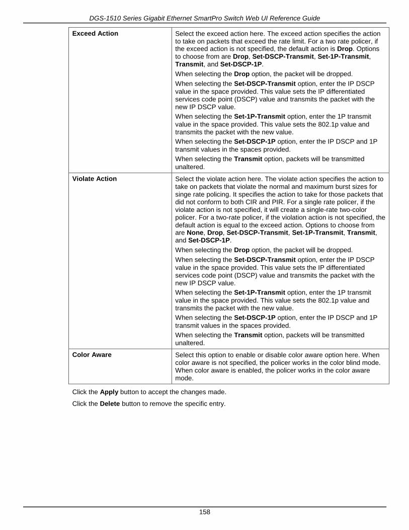
Exceed Action Select the exceed action here. The exceed action specifies the action to take on packets that exceed the rate limit. For a two rate policer, if the exceed action is not specified, the default action is Drop. Options to choose from are Drop, Set-DSCP-Transmit, Set-1P-Transmit, Transmit, and Set-DSCP-1P.
When selecting the Drop option, the packet will be dropped.
When selecting the Set-DSCP-Transmit option, enter the IP DSCP
value in the space provided. This value sets the IP differentiated services code point (DSCP) value and transmits the packet with the new IP DSCP value.
When selecting the Set-1P-Transmit option, enter the 1P transmit
value in the space provided. This value sets the 802.1p value and transmits the packet with the new value.
When selecting the Set-DSCP-1P option, enter the IP DSCP and 1P
transmit values in the spaces provided.
When selecting the Transmit option, packets will be transmitted
unaltered.
Violate Action Select the violate action here. The violate action specifies the action to take on packets that violate the normal and maximum burst sizes for singe rate policing. It specifies the action to take for those packets that did not conform to both CIR and PIR. For a single rate policer, if the violate action is not specified, it will create a single-rate two-color policer. For a two-rate policer, if the violation action is not specified, the default action is equal to the exceed action. Options to choose from are None, Drop, Set-DSCP-Transmit, Set-1P-Transmit, Transmit, and Set-DSCP-1P.
When selecting the Drop option, the packet will be dropped.
When selecting the Set-DSCP-Transmit option, enter the IP DSCP
value in the space provided. This value sets the IP differentiated services code point (DSCP) value and transmits the packet with the new IP DSCP value.
When selecting the Set-1P-Transmit option, enter the 1P transmit
value in the space provided. This value sets the 802.1p value and transmits the packet with the new value.
When selecting the Set-DSCP-1P option, enter the IP DSCP and 1P
transmit values in the spaces provided.
When selecting the Transmit option, packets will be transmitted
unaltered.
Color Aware Select this option to enable or disable color aware option here. When color aware is not specified, the policer works in the color blind mode. When color aware is enabled, the policer works in the color aware mode.
Click the Apply button to accept the changes made.
Click the Delete button to remove the specific entry.

DGS-1510 Series Gigabit Ethernet SmartPro Switch Web UI Reference Guide
159
After clicking the Two Rate Setting tab, at the top of the page, the following page will be available.
Figure 7-15 Two Rate Settings window
The fields that can be configured are described below:
Parameter Description
Aggregate Policer Name Enter the aggregate policer’s name here.
CIR Enter the Committed Information Rate (CIR) value here. This value must be between 0 and 10000000 kbps. The committed packet rate is the first token bucket for the two-rate metering.
Confirm Burst Enter the confirm burst value here. This value must be between 0 and 16384 Kbytes. The confirm burst value specifies the burst size for the first token bucket in kbps.
PIR Enter the Peak information Rate (PIR) value here. This value must be between 0 and 10000000 kbps. The peak information rate is the second token bucket for the two-rate metering.
Peak Burst Enter the peak burst value here. This value must be between 0 and 16384 Kbytes. The peak burst value is the burst size for the second token bucket in kilobytes.
Confirm Action Select the confirm action here. The confirm action specifies the action to take on green color packets. If the confirm action is not specified, the default action is to Transmit. Options to choose from are Drop, Set-DSCP-Transmit, Set-1P-Transmit, Transmit, and Set-DSCP-1P.
When selecting the Drop option, the packet will be dropped.
When selecting the Set-DSCP-Transmit option, enter the IP DSCP
value in the space provided. This value sets the IP differentiated services code point (DSCP) value and transmits the packet with the new IP DSCP value.
When selecting the Set-1P-Transmit option, enter the 1P transmit
value in the space provided. This value sets the 802.1p value and transmits the packet with the new value.
When selecting the Set-DSCP-1P option, enter the IP DSCP and 1P
transmit values in the spaces provided.
When selecting the Transmit option, packets will be transmitted
unaltered.
Exceed Action Select the exceed action here. The exceed action specifies the action to take on packets that exceed the rate limit. For a two rate policer, if the exceed action is not specified, the default action is Drop. Options to choose from are Drop, Set-DSCP-Transmit, Set-1P-Transmit, Transmit, and Set-DSCP-1P.
When selecting the Drop option, the packet will be dropped.
When selecting the Set-DSCP-Transmit option, enter the IP DSCP

DGS-1510 Series Gigabit Ethernet SmartPro Switch Web UI Reference Guide
160
value in the space provided. This value sets the IP differentiated services code point (DSCP) value and transmits the packet with the new IP DSCP value.
When selecting the Set-1P-Transmit option, enter the 1P transmit
value in the space provided. This value sets the 802.1p value and transmits the packet with the new value.
When selecting the Set-DSCP-1P option, enter the IP DSCP and 1P
transmit values in the spaces provided.
When selecting the Transmit option, packets will be transmitted
unaltered.
Violate Action Select the violate action here. The violate action specifies the action to take on packets that violate the normal and maximum burst sizes for singe rate policing. It specifies the action to take for those packets that did not conform to both CIR and PIR. For a single rate policer, if the violate action is not specified, it will create a single-rate two-color policer. For a two-rate policer, if the violation action is not specified, the default action is equal to the exceed action. Options to choose from are Drop, Set-DSCP-Transmit, Set-1P-Transmit, Transmit, and Set-DSCP-1P.
When selecting the Drop option, the packet will be dropped.
When selecting the Set-DSCP-Transmit option, enter the IP DSCP
value in the space provided. This value sets the IP differentiated services code point (DSCP) value and transmits the packet with the new IP DSCP value.
When selecting the Set-1P-Transmit option, enter the 1P transmit
value in the space provided. This value sets the 802.1p value and transmits the packet with the new value.
When selecting the Set-DSCP-1P option, enter the IP DSCP and 1P
transmit values in the spaces provided.
When selecting the Transmit option, packets will be transmitted
unaltered.
Color Aware Select this option to enable or disable color aware option here. When color aware is not specified, the policer works in the color blind mode. When color aware is enabled, the policer works in the color aware mode.
Click the Apply button to accept the changes made.
Click the Delete button to remove the specific entry.
Policy Map
This window is used to view and configure the policy map settings.
To view the following window, click QoS > Advanced Settings > Policy Map, as shown below:

DGS-1510 Series Gigabit Ethernet SmartPro Switch Web UI Reference Guide
161
Figure 7-16 Policy Map window
The fields that can be configured for Create/Delete Policy Map are described below:
Parameter Description
Policy Map Name Enter the policy map’s name here that will be created or deleted. This name can be up to 32 characters long.
Click the Apply button to accept the changes made.
The fields that can be configured for Traffic Policy are described below:
Parameter Description
Policy Map Name Enter the policy map’s name here. This name can be up to 32 characters long.
Class Map Name Enter the class map’s name here. This name can be up to 32 characters long.
Click the Apply button to accept the changes made.
Click the Delete button to remove the specific entry.
Enter a page number and click the Go button to navigate to a specific page when multiple pages exist.
To view the rules of a specific policy map, click the policy map name in the table (the Policy Map Name will toggle to the bold font).

DGS-1510 Series Gigabit Ethernet SmartPro Switch Web UI Reference Guide
162
Figure 7-17 Policy Map (View Rules) window
Click the Set Action button to configure the action for the policy map.
Click the Policer button to configure the policer action for the policy map.
Click the Delete button to remove the specific entry.
After clicking the Set Action button, the following window will appear.
Figure 7-18 Set Action window
The fields that can be configured are described below:
Parameter Description
None Select this option to match nothing to this policy map.
Specify Select the option to match something to this policy map.
New Precedence Select a new precedence for the packet. This value must be between 0 and 7. Tick the IPv4 only to only mark IPv4 precedence. Setting the
precedence will not affect the CoS queue selection.
New DSCP Select a new DSCP for the packet. This value must be between 0 and 63. Tick the IPv4 only to only mark IPv4 precedence. Setting DSCP
will not affect the CoS queue selection.
New CoS Select a new CoS value for the packet. This value must be between 0 and 7. Setting CoS will not affect the CoS queue selection.
New CoS Queue Select a new CoS queue for the packet. This value must be between 0

DGS-1510 Series Gigabit Ethernet SmartPro Switch Web UI Reference Guide
163
and 7. This overwrites the original CoS queue selection.
Click the Apply button to accept the changes made.
Click the Back button to return to the previous window.
After clicking the Policer button, the following window will appear.
Figure 7-19 Police Action window
The fields that can be configured are described below:
Parameter Description
None Select this option to match nothing to this policy map.
Specify Select the option to match something to this policy map.
Average Rate Enter the average rate in kilobits per second.
Normal Burst Size Enter the normal burst size in kilobytes.
Maximum Burst Size Enter the maximum burst in kilobytes.
Conform Action Select the action to take on green color packets. Options to choose from are Drop, Set-DSCP-Transmit, Set-1P-Transmit, Transmit, and Set-DSCP-1P.
Exceed Action Select the action to take on yellow color packets. Options to choose from are Drop, Set-DSCP-Transmit, Set-1P-Transmit, Transmit, and Set-DSCP-1P.
Violate Action Select the action to take on red color packets. Options to choose from are None, Drop, Set-DSCP-Transmit, Set-1P-Transmit, Transmit, and Set-DSCP-1P.
Color Aware Select this option to enable or disable color aware mode.
Click the Apply button to accept the changes made.
Click the Back button to return to the previous window.
Policy Binding
This window is used to view and configure the policy binding settings.

DGS-1510 Series Gigabit Ethernet SmartPro Switch Web UI Reference Guide
164
To view the following window, click QoS > Advanced Settings > Policy Binding, as shown below:
Figure 7-20 Policy Binding window
The fields that can be configured are described below:
Parameter Description
Unit Select the switch unit that will be used for this configuration here.
From Port / To Port Select the appropriate port range used for the configuration here.
Direction Select the direction option here. Option to choose from is Input. Input
represents Input specified ingress traffic.
Policy Map Name Enter the policy map name here. This name can be up to 32 characters long. Select the None option to not tie a policy map to this
entry.
Click the Apply button to accept the changes made.


![Basic Settings & Org[1].Srtucture](https://static.fdocuments.us/doc/165x107/577d22aa1a28ab4e1e97f1f4/basic-settings-org1srtucture.jpg)