QUALITY MONITORING SYSTEMphed.bih.nic.in/Docs/Quality-Monitoring-System.pdf · 23 HDPE High density...
213
Rural Piped Water Supply QUALITY MONITORING SYSTEM PUBLIC HEALTH ENGINEERING DEPARTMENT NIRMAN BHAWAN PATNA-800015
Transcript of QUALITY MONITORING SYSTEMphed.bih.nic.in/Docs/Quality-Monitoring-System.pdf · 23 HDPE High density...

Rural Piped Water Supply
QUALITY MONITORING
SYSTEM
PUBLIC HEALTH ENGINEERING DEPARTMENTNIRMAN BHAWANPATNA-800015

i
ABBREVIATION
Sl. No Abbreviation Description
1 AC Asbestos cement
2 BIS Bureau of Indian standard
3 BOQ Bill of quantities
4 °C Degree Celsius temperature
5 CI Cast iron
6 Cm Centimetre
7 Cum/ M3 Cubic meter
8 CWR Clear water reservoir
9 Dia Diameter
10 PD Project Director
11 DPMC District Programme Management Cell
12 NIT Notice inviting tender
13 DT Departmental Team
14 E.E. Executive Engineer
15 FC Fully covered
16 Fig Figure
17 GC Galvanized corrugated
18 GI galvanized iron

ii
19 Gm Gram
20 GoB Government of Bihar
21 Govt. Government
22 GP Gram Panchayat
23 HDPE High density poly ethylene
24 HRD Human resources development
25 IE
Independent Engineer
26 ISI Indian Standard Institution
27 ITP Inspection test plan
28 J.E. Junior Engineer
29 Kg Kilogram
30 Kl Kilo Litre
31 Km Kilo meter
32 M Meter
33 MC Manufacturer Certificate
34 MH Manhole
35 Ml Millilitre
36 Mm Millimetres
iii
37 M3
Cubic meter
38 M&E Monitoring and evaluation
39 NC Not covered
40 No. Number
41 OHSR Over head service reservoir
42 O&M Operation and Maintenance.
43 PC Partially covered
44 PHE Public Health Engineering.
45 PIU
Project Implementation Unit
46 12 PQM
Principal Quality Monitor
47 RWS Rural water supply scheme
48 PVC Poly vinyl chloride
49 P.W.D. Public works department
50 QMC Quality Monitoring Cell
51 QA/QC Quality assurance /Quality Control
52 QAP Quality assurance plan
53 QCC
Quality Control Check List
54 QCF Quality control format
55 QC-M Quality control of material
56 QC-P Quality control Process
iv
57 QMSW Quality management and surveillance wing
58 QS Quality system
59 RCC Reinforced cement concrete
60 Re / Rs Rupee / Rupees
61 RI Requiring Improvement
62 SDE Sub division Engineer
63 S.E. Superintending Engineer
64 SPMC State Programme management cell
65 SQMS
Sate Quality Management System
66 STP Sewage treatment plant
67 SW Stone ware
68 SW Ap Sector wide approach
69 T Tonne
70 TOR Terms of reference
71 TMT Thermo mechanically treated
72 TP Third party
73 WQM&S Water quality monitoring & surveillance
74 WS &SM Water supply & sanitation monitoring
75 WTP Water treatment plant
INDEX
1.0 INSTITUTIONAL STRENGTHENING OF PUBLIC HEALTH ENGINEERING DEPARTMENT ............................................ 1
2.0 CREATION OF INDEPENDENT QUALITY MONITORING CELL ................................................................................... 2
3.0 SET UP OF QUALITY MONITORING CELL ........................................................................................................... 4
3.1 FIRST TIER............................................................................................................................................................. 4
3.2 SECOND TIER ........................................................................................................................................................ 5
3.3 THIRD TIER ........................................................................................................................................................... 6
4.0 OPERATIONAL SYSTEM OF QUALITY MONITORING CELL ...................................................................................... 8
4.1 INSPECTION PROGRAMME ................................................................................................................................... 8
4.2 PRIORITIZATION OF WORKS FOR SYSTEMATIC INSPECTION ................................................................................. 8
4.3 INSPECTION, OBSERVATION AND GRADING OF WORK ......................................................................................... 9
4.4 REPORTING AND SUBMISSION OF INSPECTION REPORT..................................................................................... 11
4.5 ACTION TAKEN REPORT ...................................................................................................................................... 11
5.0 GUIDELINES ON ACTION TAKEN REPORT ............................................................................................................ 11
5.1 AT PIU LEVEL THE FOLLOWING ACTION SHALL BE TAKEN ................................................................................... 11
5.2 AT QUALITY MONITORING CELL (QMC) LEVEL, THE FOLLOWING ACTIONS SHALL BE TAKEN .............................. 12
6.0 ORGANIZATIONAL SET UP OF QUALITY MONITORING CELL ................................................................................ 13
6.1CHIEF ENGINEER (QMC) ....................................................................................................................................... 14
6.2 SUPERINTENDING ENGINEER (QMC) .................................................................................................................. 15
6.3 EXECUTIVE ENGINEER (QMC).............................................................................................................................. 16
6.4 ASSISTANT ENGINEER (QMC):............................................................................................................................. 17
6.5 QUALITY ASSURANCE SPECIALIST ....................................................................................................................... 18
6.6 MIS SPECIALIST ................................................................................................................................................... 19
7.0 QUALITY CONTROL MECHANISM ........................................................................................................................ 19
7.1 1ST TIER QUALITY CONTROL MECHANISM ........................................................................................................... 19
7.2 2ND TIER QUALITY CONTROL MECHANISM .......................................................................................................... 20
7.3 3RD TIER QUALITY CONTROL MECHANISM .......................................................................................................... 21
8.0 BUDGET FOR PROPOSED QUALITY MONITORING SYSTEM ................................................................................. 23
9.0 WEB BASED ONLINE MONITORING SYSTEM ....................................................................................................... 24
9.1 ONLINE MONITORING RESPONSIBILITIES ........................................................................................................... 25
10.0 OPERATING THE STATE QUALITY MANAGEMENT SYSTEM ................................................................................ 26
11.0 INSPECTION, REPORTING OUTPUT & ANALYSIS (FOR TIER 2 & 3 ) ........................................................ 28
11.1 QUALITY CONTROL CHECKLIST.......................................................................................................................... 29
11.2 QUALITY FIELD INSPECTION REPORT ............................................................................................................. 32
11.3 QUALITY CONTROL DOCUMENTS AND TESTING DETAILS.................................................................................. 34
11.4 AVAILIBILITY OF SITE DOCUMENT..................................................................................................................... 35

11.5 FIELD LABORATORY EQUIPMENT AVAILABLE AT SITE (AS PER PROVISIONS OF SBD/CONTRACT DOCUMENT) . 35
11.6 MATERIAL/ WORKS TESTED BY CONTRACTOR (FIELD LABORATORY) (AS PER PROVISIONS OF SBD/CONTRACT
DOCUMENT) ............................................................................................................................................................ 36
11.7 EQUIPMENTS/ T&P AVAILABLE AT SITE (AS PER PROVISIONS OF SBD/CONTRACT DOCUMENT) ...................... 37
11.8 DETAILS OF MANUFACTURER/3RD PARTY INSPECTION CERTIFICATES (AS PER PROVISIONS OF SBD/CONTRACT
DOCUMENT) ............................................................................................................................................................ 38
11.9 DEPARTMENTAL TEAM INSPECTION AT MANUFACTURING PREMISES (AS PER PROVISIONS OF SBD/CONTRACT
DOCUMENT) ............................................................................................................................................................ 39
11.10 PENALITIES ON A/C OF NONCONFORMANCE OF WORK ................................................................................. 39
11.11 SAMPLE TAKEN FOR TESTING DURING FIELD VISIT ......................................................................................... 40
11.12: TEST CONDUCTED BY INSPECTION TEAM (AS PER PROVISIONS OF SBD/CONTRACT DOCUMENT) ................. 41
12.0 INTRODUCTION ................................................................................................................................................ 43
12.1 BACK GROUND: ................................................................................................................................................ 45
12.2 QUALITY DEFINITION ................................................................................................................................... 46
12.3 QA/QC MANUAL.......................................................................................................................................... 47
12.4 Q A/Q C DUTIES ........................................................................................................................................... 48
12.5 QUALITY ASSURANCE BY DEPARTMENTAL ENGINEERS DURING INSPECTION ............................................. 50
13.0 CONSTRUCTION QUALITY CONTROL ................................................................................................................. 53
13.1 INTRODUCTION ........................................................................................................................................... 53
13.2 TESTING ....................................................................................................................................................... 53
13.3 INSPECTIONS OF SITES ................................................................................................................................. 56
13.3.1 EVERYDAY SUPERVISION ......................................................................................................................... 56
13.3.2 PERIODICAL INSPECTION FOR QUALITY ................................................................................................... 56
13.4 QUALITY CERTIFICATION ............................................................................................................................. 58
14.0 CONTROL OF MATERIALS AND EQUIPMENT ..................................................................................................... 59
14.1 GENERAL ..................................................................................................................................................... 59
14.2 MANDATORY TESTS TO BE PERFORMED ...................................................................................................... 59
14.3 MATERIALS AND EQUIPMENTS CERTIFIED BY MANUFACTURER .................................................................. 61
14.4 MATERIAL AND EQUIPMENTS INSPECTED BY DEPARTMENTAL TEAM AT THE FACTORY ............................. 62
15.0 CONTROL OF CIVIL STRUCTURAL WORKS AND WATER RETAINING STRUCTURES ....................................... 63
15.1 CEMENT CONCRETE & MORTAR .................................................................................................................. 63
15.1.1 PROPORTIONS OF CEMENT CONCRETE .................................................................................................... 63
15.1.2 PROPORTIONS OF CEMENT MORTAR ...................................................................................................... 64
15.2 WATER WORKS STRUCTURES ...................................................................................................................... 66
15.3 CONVENTIONAL UNITS OF CANAL AND SURFACE SOURCE AS PER REQUIREMENT OF THE PROJECT BASED
WATER SUPPLY SCHEMES ........................................................................................................................................ 67
16.0 CONTROL OF PIPELINE WORKS ......................................................................................................................... 69
16.1 GENERAL ..................................................................................................................................................... 69
16.2 EXCAVATION AND BACKFILLING .................................................................................................................. 69
16.2.1 LAYING AND JOINTING OF UPVC PIPES AND SPECIALS ............................................................................. 70
16.2.2 LAYING & JOINTING OF HDPE PIPES AND SPECIALS ....................................................................................... 70
16.2.3 TRENCH PREPARATION ............................................................................................................................ 73
16.2.4 COVER TO PIPES ...................................................................................................................................... 73
16.2.5 PIPELINE LOG BOOK ................................................................................................................................ 73
16.2.6 THRUST BLOCK CONSIDERATIONS ........................................................................................................... 74
16.2.7 FLANGED PIPES ........................................................................................................................................ 74
17.0 CONTROL OF MECHANICAL & ELECTRICAL WORKS ....................................................................................... 75
17.1 PREPARATORY INSPECTIONS: ...................................................................................................................... 75
17.2 INSTALLATION INSPECTIONS AND TESTS: .................................................................................................... 75
17.3 INSTALLATION VERIFICATION INSPECTIONS: ............................................................................................... 76
17.4 SYSTEM TESTS: ............................................................................................................................................ 76
17.5 INTEGRATED TESTS: ..................................................................................................................................... 76
17.6 COMMISSIONING TESTS: ............................................................................................................................. 76
17.7 FINAL INSPECTIONS: .................................................................................................................................... 76
17.8 PARAMETERS TO BE DECLARED BY THE MANUFACTURER ........................................................................... 77
17.9 PUMP TEST RECORD .................................................................................................................................... 77
18.0 PROCEDURE OF SAMPLING AND TESTING OF MATERIALS ............................................................................ 78
18.1 CEMENT ....................................................................................................................................................... 78
18.1.1 SAMPLING PROCEDURES AND SAMPLE COLLECTIONS ............................................................................. 78
18.1.2 TEST FOR CEMENT ................................................................................................................................... 79
18.1.3 TEST FOR FINENESS ................................................................................................................................. 79
18.1.4 TEST FOR COMPRESSIVE STRENGTH ........................................................................................................ 80
18.2 AGGREGATE ................................................................................................................................................ 82
18.2.1 SAMPLING PROCEDURES AND SAMPLE COLLECTIONS ............................................................................. 82
18.2.2 TEST FOR FINE AGGREGATE (SAND) ......................................................................................................... 83
18.2.3 SIEVE ANALYSIS & FINENESS MODULUS .................................................................................................. 83
18.2.4 SIEVE ANALYSIS & FINENESS MODULUS TEST (STONE) ............................................................................ 85
18.3 BRICKS ......................................................................................................................................................... 88
18.3.1 SAMPLING PROCEDURES AND SAMPLE COLLECTIONS ............................................................................. 88
18.3.2 TEST FOR BRICKS: IS: 1077-1992 .............................................................................................................. 88
18.3.3 VISUAL..................................................................................................................................................... 88
18.3.4 DIMENSIONS ........................................................................................................................................... 89
18.3.5 WATER ABSORPTION ............................................................................................................................... 90

18.3.6 EFFLORESCENCE ...................................................................................................................................... 90
18.3.7 COMPRESSIVE STRENGTH ........................................................................................................................ 91
18.4 CONCRETE ................................................................................................................................................... 92
18.4.1 SAMPLING PROCEDURES AND SAMPLE COLLECTIONS ............................................................................. 92
18.4.2 TEST OF CEMENT CONCRETE.................................................................................................................... 93
18.4.2.1 SLUMP TEST:............................................................................................................................................... 93
18.4.2.2 COMPRESSIVE TEST ............................................................................................................................. 94
18.5 STEEL ........................................................................................................................................................... 96
18.5.1 SAMPLING PROCEDURES AND SAMPLE COLLECTIONS ............................................................................. 96
18.5.2 TEST OF STEEL FOR REINFORCEMENT IS: 1786-2008 ................................................................................ 96
18.6 PIPES ........................................................................................................................................................... 98
18.6.1 SAMPLING PROCEDURES AND SAMPLE COLLECTIONS ............................................................................. 98
18.6.2 TEST OF U P V C PIPE FOR POTABLE WATER SUPPLY IS 4985-2000 ........................................................... 99
18.6.3 TEST OF GLAZED STONE WARE PIPES IS: 651-2007 ................................................................................ 100
18.6.4 TEST OF R.C.C PIPES ............................................................................................................................... 101
18.6.5 TEST OF HDPE PIPES.............................................................................................................................. 102
18.6.6 TEST OF G.I. PIPES.................................................................................................................................. 103
18.7 WATER FOR CONSTRUCTION PURPOSES.................................................................................................... 104
18.7.1 SAMPLING OF WATER ........................................................................................................................... 104
18.7.2 METHOD AND STANDARDS ................................................................................................................... 104
18.8 PRECAST CONCRETE MANHOLE COVER AND FRAMES ............................................................................... 105
18.9 PLASTIC ENCAPSULATED FOOTRES ............................................................................................................ 106
18.10 LDPE SHEET ........................................................................................................................................... 106
18.11 TEST FOR TUBE WELL ............................................................................................................................. 106
18.11.1 WATER SAMPLING ..................................................................................................................................... 106
18.11.2 SAMPLING FOR PHYSICAL AND CHEMICAL ANALYSIS ................................................................................ 106
18.11.3 SAMPLING FOR BACTERIOLOGICAL ANALYSIS............................................................................................ 107
18.12 CHECKS AND TESTS OF FINISHED WORKS ............................................................................................. 109
18.13 MANDATORY TESTS............................................................................................................................... 111
18.14 HYDROSTATIC TESTS OF PIPELINES ............................................................................................................... 119
18.15 TEST REPORT FORMATS......................................................................................................................... 120
18.16 BRANDS OF MATERIAL AND EQUIPMENTS ............................................................................................ 120

QUALITY
MONITORING CELL


1
1.0 Institutional Strengthening of Public Health
Engineering Department
The Public Health Engineering Department (PHED), Govt of Bihar has the overall
responsibility of managing and monitoring activities to provide drinking water in the
state of Bihar. Improved potable water supply and sanitation facilities and services
are critical to enhance public health and improve human development outcomes,
more so for rural households.
Though the State of Bihar has recorded an impressive performance in providing safe
drinking water to its rural households, further improvements are required in terms of
quantity, quality, equity and sustainability.
To address these issues in a coherent, concerted and urgent manner, new initiatives
have to be taken in a mission mode.
The enormous task of building and maintaining water supply schemes poses a
formidable challenge in so far as assuring the quality technical workmanship and
overall output along with real time rectification interventions is concerned. Given the
manpower constraint of the department, system of various tiers of inspection, testing
and measurements, reporting and rectification complied with engineering and
administrative interventions is therefore urgently required. The system aims at
creating a complete institutional framework along with a complete description of
roles and responsibilities, testing requirements and protocols, methods and
procedures and systematic online data input and analysis.
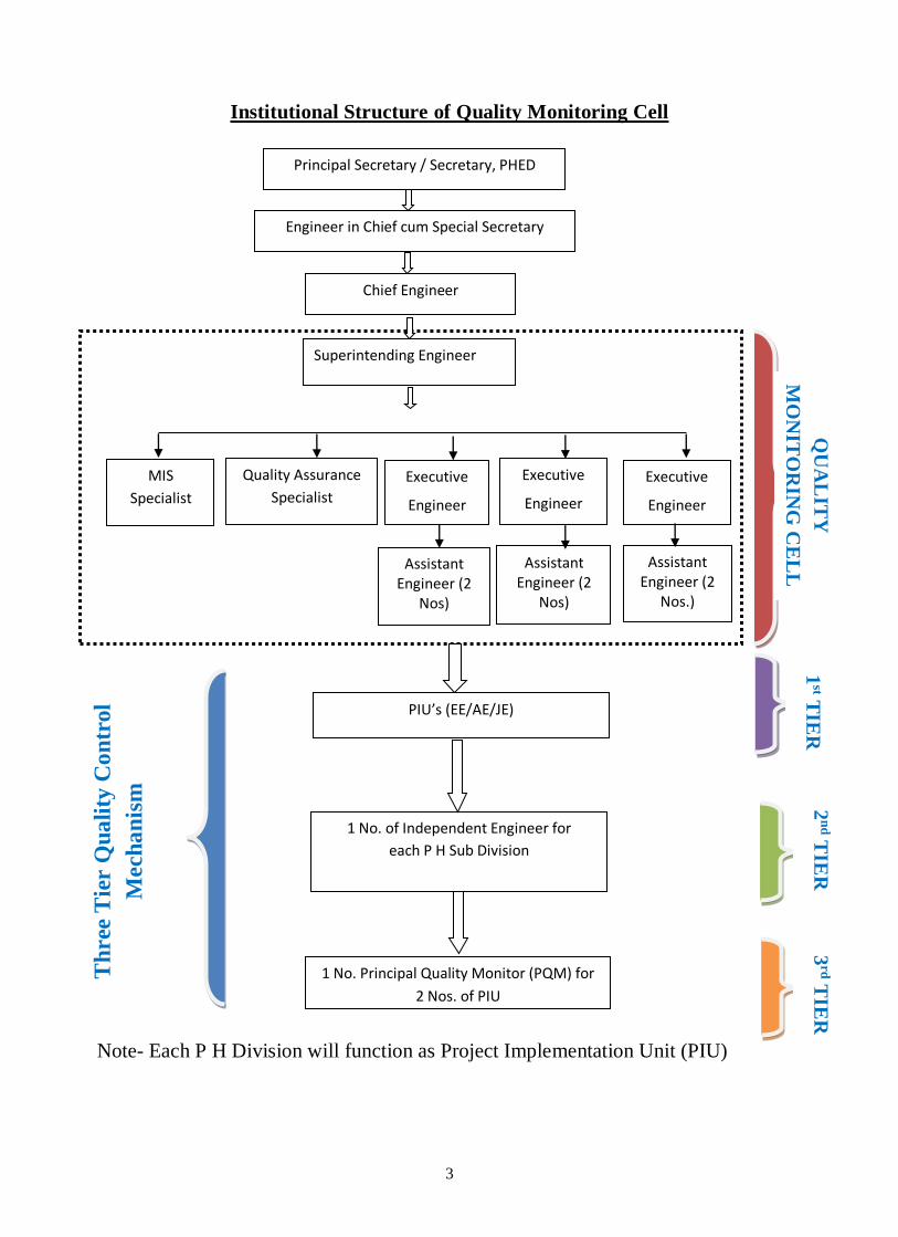
The policy conceives of three Tier Quality Monitoring System. Existing PH
Divisions will function as Programme Implementation Unit (PIU) i.e. the First Tier
of the system. Graduate Engineers will be hired to function as Independent Engineer
(IE) which will constitute the second Tier of the System. Retired Senior Engineers
from State/Central Organisation dealing with the Water Supply/Sewerage/Sanitation
Project will be hired to function as Principal Quality Monitors (PQM), which will
constitute the Third Tier of the System.

2
Manual inspection and reporting system is being strengthened and it is
supposed to use technology to obviate need of cumbersome and burdensome
inspection and monitoring mechanism which has obviously proved inadequate for the
Public Health Engineering Department.
It goes without saying that the framework is in addition to the codal provisions
of Bihar PWD code and other relevant rules of the state.
2.0 Creation of Independent Quality Monitoring Cell
Public Health Engineering Department is the statutory authority for designing,
planning, implementing, monitoring, operating and undertaking maintenance of
Water Supply Schemes irrespective of the source of funds for the same.
To keep the pace of contemporary requirements, it is felt the need to set up a Quality
Monitoring Cell to bring about innovative reforms and the best practices in
enhancing the efficiency of the department.
Quality Monitoring Cell is primarily being made operational to take care of all the
projects being taken up under the Department.
The QMC will work on a three-tier quality management mechanism, which will be
operationalized with web based online system with centralised database for ensuring
that the quality of assets created conform to the prescribed standards. Institutional
Structure of QMC is given as under:
3
Institutional Structure of Quality Monitoring Cell
Note- Each P H Division will function as Project Implementation Unit (PIU)
Th
ree
Tie
r Q
ua
lity
Co
ntr
ol
Mech
an
ism
Chief Engineer
Executive
Engineer
Executive
Engineer
Assistant Engineer (2
Nos)
Assistant Engineer (2
Nos.)
Assistant Engineer (2
Nos)
Superintending Engineer
1 No. of Independent Engineer for
each P H Sub Division
1 No. Principal Quality Monitor (PQM) for
2 Nos. of PIU
Executive
Engineer
QU
AL
ITY
MO
NIT
OR
ING
CE
LL
2n
d TIE
R
3rd T
IER
PIU’s (EE/AE/JE)
1st T
IER
Quality Assurance
Specialist
MIS
Specialist
Principal Secretary / Secretary, PHED
Engineer in Chief cum Special Secretary

4
3.0 Set up of Quality Monitoring Cell
The Quality Monitoring Cell envisages a three-tier Quality Monitoring mechanism;
which has been described as below
3.1 First Tier
The first tier shall be managed by PIU. The stipulated tests as per the contract have to
be conducted. The test results shall be recorded in the prescribed Quality Control
Registers. If the Contractor is responsible for infrastructural arrangements for Quality
Control Tests, then the following check mechanism are prescribed.
1) All the tests should be conducted by the designated qualified staff of the
Contractor and the Quality Control Register Part-I should be maintained by
him.
2) For effective Quality Control, the following percentages of various categories
of tests will be done by the designated staff of Contractor in the presence of
the JE/AE/EE:
a) 50 percent of the tests are conducted in the presence of the JE.
b) 20 percent of the tests are conducted in the presence of the AE
c) 5 per cent of the tests shall be conducted in the presence of the EE.
All the test results are to be recorded in Quality Control Register-I.
The monthly return of the tests will be submitted in the prescribed Performa by the
Junior Engineer & Assistant Engineer to the Executive Engineer in the first week of
every month. The Executive Engineer will review this return regularly to see that the
Quality Control tests are being performed at the desired frequency and with required
accuracy. The EE will also see that the Non-Conformance reports are issued by the
AE whenever Non - Conformance occurs and the Contractor promptly takes actions
on Non - Conformance reports. The reporting as enumerated above shall also be
carried out on online mode on the State Quality Monitoring Portal. Restricted access

5
to the contractors to the online monitoring tool shall be also being provided for
viewing and compliance thereof in case of Non-Conformance.
3.2 Second Tier
As the second tier of Quality Control structure, periodic inspections of works will be
carried out by the Independent Engineers, whose services to be hired on contract/
empanelment/ outsourcing basis by the Department and they will be independent of
the Executive Engineer/PIUs. This tier of Quality monitoring is very important and
has been designed to see that the Executing agency is carrying out the Quality
Controls as per specifications. The following process is to be adopted for 2nd Tier
Quality Monitoring.
1) The programme of IE shall be drawn up through systematic sampling in
online mode in such a way that every work is inspected at-least three
times. The first & second inspection of every work shall be carried out
during the execution of work and the last inspection shall be carried out on
the completion of every work, within one month of its completion.
2) The Quality Monitoring Cell will draw up a monthly Schedule for IE (Sub
Division/ Division wise) so as to ensure systematic coverage.
3) The Quality Monitoring Cell will send the IE’s reports along with
direction to the Project Implementing Unit with a copy to the concerned
SE/CE.
4) The IE will interact with PIUs and the Contractors and inspect Field/
District Laboratories to ensure smooth functioning of the Quality Control
Mechanism.
5) The IE will have to interact with the PHED HQ’s in matters relating to the
design, testing and execution.
6) IE will prepare a monthly report and send to Central Quality Monitoring
Cell containing the analysis which would include findings of the PIU

6
reports, IE reports, action taken in individual cases and systemic
deficiencies detected and remedied.
All cases of delay in reporting compliance and major cases of deviation from
acceptable Quality shall be taken seriously.
It is to note that all the reports shall be submitted online into the web portal.
The IE would be given a detailed format in online mode for the inspection report that
should cover the following aspects.
a) Provisions made in estimates with regard to site requirements.
b) Management of the contract, deployment of qualified staff by the Contractor
and establishment of a functional Quality Control Laboratory by the
Contractor.
c) Construction Programme and progress of work.
d) Execution methodology and adherence to specifications.
e) Arrangement at Quality Testing Laboratories.
f) Record of Tests- Quality Control Registers and their up to date maintenance.
g) Accuracy of Quality Control Tests, issuance of Non Conformance Reports
(NCR) and action of Contractor on NCRs.
h) Inspection by departmental officer and compliance of their instructions.
i) Other issues including the technical knowledge of the staff of the executing
agency and the Contractor.
3.3 Third Tier
The third tier shall comprise of Principal Quality Monitors (PQM’s), whose services
to be hired on contract/ empanelment/ outsourcing basis by the Department. They
will be generally retired Senior Engineers from State/Central organizations dealing
with water supply, sewerage and sanitation project.

7
The third tier of Quality Monitoring is oriented more towards verification and review
of systems and procedures being adopted at 1st and 2nd tier of Quality Monitoring,
so that it can be ensured that specified requirements for Quality Management are
being met.
The Principal Quality Monitors are required to visit the work in accordance with the
priority indicated in the guidelines issued to them at under section "Prioritization of
Works for Inspection".
Roles and Responsibilities:
a) PQM’s will carry out Quality testing of works on random sampling basis from
the priority list, mainly in order to confirm that the programme implementation
and Quality Control System is working satisfactorily.
b) PQMs are expected to make constructive suggestions relating to procedural
aspects in addition to locating problems at individual work level.
c) To bring out systemic deficiencies/ shortcomings and suggestions for
improvement in
Design and Estimation
Execution and Supervision
Quality Control
Contracting etc.
d) PQM’s will submit all individual work wise Inspection Reports along with a
general analysis based on the works inspected by him as well as other
inspection reports accessed by him.
Since the role of the PQM’s is guidance and improvement rather than mere 'fault
finding', the analysis is an extremely important aspect and must be prepared with
care. The SE operating from Quality Monitoring Cell will be responsible for
reporting compliance on the issues raised by PQMs and observations in this regard.
8
The analysis of the Reports of the PQMs will be done at Quality Monitoring Cell and
necessary directions shall be issued for necessary compliance as quickly as possible.
4.0 Operational System of Quality Monitoring Cell
4.1 Inspection Programme
Inspection programme of the Cell shall be drawn up through systematic sampling in
online mode for inspecting the works under following conditions:
a) Systematic inspection of all sites to check quality of work and to check
whether the execution of work is being carried out as per the agreement.
b) On directions of the Principal Secretary / Secretary, PHED directs to inspect
any particular Scheme
c) Any grievances/ complaint registered against the quality of any particular
Scheme
4.2 Prioritization of works for Systematic Inspection
All Schemes shall get inspected by Quality Monitoring Cell in systematic manner
with following priorities:
1. Priority 1:
Works which are at initial stage. This is with a view to examine the system and
procedures which is being followed by the PIU and the Contractor. Intervention
at this stage would help in ensuring that subsequent stages of the work are carried
out after system deficiencies are removed.
2. Priority 2
Ongoing works
3. Priority 3
Ongoing works that have not been inspected in the last 3 months.
4. Priority 4
Completed works.

9
5. Priority 5
Complaint cases and ATR cases on case to case basis.
4.3 Inspection, Observation and Grading of Work
The role of the officers in Quality Monitoring Cell is to critically examine the work
and give feedback about quality of Scheme works and quality related shortcomings
for systemic improvements.
I) How to make observations
Various items and sub-items involved in construction of a rural water supply
schemes have been listed in Quality control checklist (QCC). Observation shall be
recorded on following items
Sl.
No. Items
1 Quality Control Arrangements
2 Material
3 Installation, testing & Commissioning of
High yield Tube well
4
Installation, testing and Commissioning of
pumping plants and other electromechanical
works
5 Installation, testing and commissioning of
water treatment plants
6
Civil Works : Staging for Water Storage
Structure, Installation of PVC Storage Tank,
Construction of Pump House & Toilet
7
Laying, Testing and Commissioning of
pipes, specials and other related works for
Distribution Network
8 Providing House Connection
9 Trial-runs of the scheme and water quality
testing of 5% total House Hold connection
10
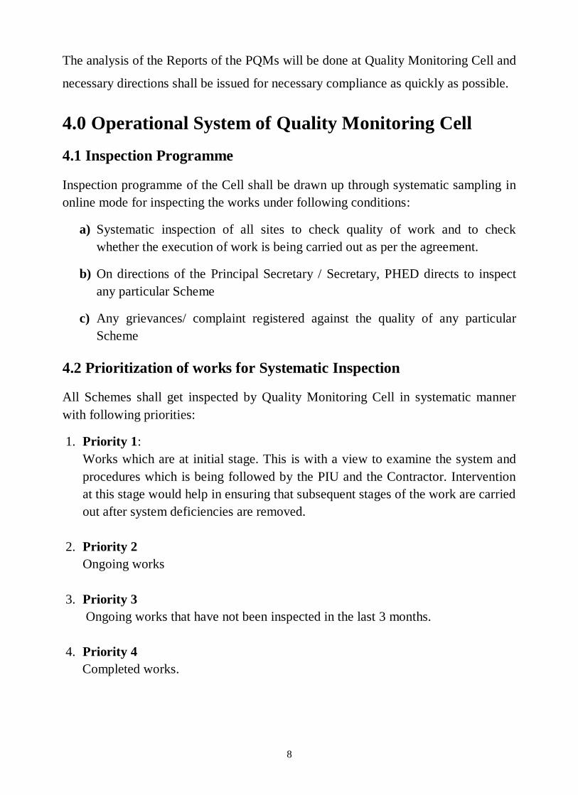
ii) How to organize inspection
It is expected to traverse through the entire project to ascertain the quantum of work
and other aspects of the work. After the traverse, the locations for detailed
observations shall be decided.
In case of on-going work/item of work it is easier to take samples of material.
However, in case of completed work/item it may be difficult to take samples.
iii) Sub-item/Item wise Grading and Overall Grading of Work
The sub-item wise grading of every item of work would be entered. The overall
Item Grading would be entered and shall be calculated in the following manner:
Sl.
No. Items
Available
Grade
1 Quality Control Arrangements
2 Material
3 Installation, testing & Commissioning of
High yield Tube well
4 Installation, testing and Commissioning of
pumping sets
5 Installation, testing and commissioning of
water treatment plants sets
6
Civil Works : Staging for Water Storage
Structure, Installation of PVC Storage Tank,
Construction of Pump House & Toilet
7
Laying, Testing and Commissioning of
pipes, specials and other related works for
Distribution Network
8 Providing House Connection
9 Trial-runs of the scheme and water quality
testing of 5% total House Hold connection
Overall Grading

11
Grading shall be of 3 types vis-a-vis:
1. Unsatisfactory. (U):
If, any of the items in item no. 3, 4, 5 & 7 are graded as ‘U’, overall grading of
the work shall be ‘U’ i.e. ‘Unsatisfactory’.
2. Satisfactory but requires Improvement. (S-RI)
If, all the items given in above four items are ‘S’ but grading in any of other
items is ‘U’ or ‘RI’, the overall grading of work shall be ‘S-RI’ i.e.
Satisfactory but Requiring Improvement.
3. Satisfactory. (S)
If grading of all items is ‘S’, the overall grading of work shall be ‘S’ i.e.
‘Satisfactory’.
4.4 Reporting and Submission of Inspection Report
All the observation compiled in desired format will be submitted on line for further
action. Quality Assurance Specialist will analyse the grade given on time-to-time.
4.5 Action Taken Report
Action Taken report shall be prepared and submitted online, if grading shall be ‘U’or
‘S-RI’.
5.0 Guidelines on Action Taken Report
5.1 At PIU level the following action shall be taken
1) After the inspections in the district are over the copy of reporting format will
be handed over by the IE to the PIU and copies will be sent to the Quality
Monitoring Cell within 7 days after completing inspection. Unless the PIU
disagrees with the conclusion/recommendation, rectification work should be
ordered immediately by the PIU. In case the Executive Engineer PIU feels that
any portion of the inspection report or the suggested rectification is not
appropriate, he shall make a full report to the Quality Monitoring Cell.

12
2) The Action Taken Report will be prepared by Executive Engineer in the
prescribed Format and will be sent to the Quality Monitoring Cell.
3) The Action taken report (ATR) submitted should be comprehensive, i.e.
merely writing letter to the Quality Monitoring Cell or to the subordinate
doesn't constitute action taken and should not be treated as ATR.
5.2 At Quality Monitoring Cell (QMC) level, the following actions
shall be taken
1) On receipt of the report of the IE, the QMC will immediately remind the PIU
for taking action and reporting on every para of the report. He will also initiate
action on the general issues brought out by the IE in his report for remedial
action by all concerned.
2) In case there is disagreement with the finding/recommendation in an IE
Report, this should be communicated as part of the Action taken Report of
PIU, duly supported by test results.
3) The QMC will generally compare findings of the IE and PIU to find if the two
are in conformity.
4) The QMC will grade the works as 'satisfactory' or 'unsatisfactory' or
satisfactory requiring improvement after, scrutiny of IE reports.
5) The QMC shall prepare and send a Report to Principal Secretary/Secretary and
Engineer in Chief PHED. The report shall contain analysed performance of the
IE, general deficiencies observed/highlighted through IE reports and action
taken/required to be taken to remedy systematic deficiencies at organisational
level in order to improve the Quality of Schemes and programme performance
6) The QMC will analyse ATRs for their compliance and further follow up if
required.
7) QMC at periodic intervals shall get the IE reports as well as the Annual
Quality Report, who shall make recommendations on systematic action to be
taken at organizational level to improve Quality of Schemes and programme
performance in the state.

13
Flow Diagram: Operational System of Quality Monitoring Cell
Formulation of Inspection Programme
Systematic Inspection of scheme
On directions of the Secretary, PHED
Any particular grievances/ Complain on scheme
Prioritization of works for Systematic Inspection
Creation of Inspection Team
Inspection, Observation and Grading of Work
Online Report Submission
Analysis of report by Quality Assurance Specialist
Brief of Analysis submitted to Principal
Secretary/Secretary, PHED
Action Taken Report
on Grading- U & S-RI
14
6.0 Organizational set up of Quality Monitoring Cell
The Independent Quality Monitoring Cell shall be under the administrative control of
the Principal Secretary/Secretary, Public Health Engineering Department and shall be
supported by the pattern as set forth above. The duties and responsibilities of
individual officers are:
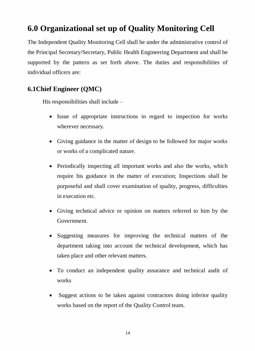
6.1Chief Engineer (QMC)
His responsibilities shall include –
Issue of appropriate instructions in regard to inspection for works
wherever necessary.
Giving guidance in the matter of design to be followed for major works
or works of a complicated nature.
Periodically inspecting all important works and also the works, which
require his guidance in the matter of execution; Inspections shall be
purposeful and shall cover examination of quality, progress, difficulties
in execution etc.
Giving technical advice or opinion on matters referred to him by the
Government.
Suggesting measures for improving the technical matters of the
department taking into account the technical development, which has
taken place and other relevant matters.
To conduct an independent quality assurance and technical audit of
works
Suggest actions to be taken against contractors doing inferior quality
works based on the report of the Quality Control team.

15
To review functioning of the field testing laboratories and suggest
remedial measures for improving the standard of their performance.
6.2 Superintending Engineer (QMC)
His responsibilities shall include –
Overall responsibility of effective functioning of Quality Monitoring
Cell. He will look after the day-to-day activity of cell.
Issue of appropriate instructions in regard to inspection for works
wherever necessary.
Giving guidance in the matter of design to be followed for major works
or works of a complicated nature in consultation with Chief Engineer
(QMC).
Periodically inspecting all important works and also the works, which
require his guidance in the matter of execution; Inspections shall be
purposeful and shall cover examination of quality, progress, difficulties
in execution etc.
Suggesting measures for improving the technical matters of the
department taking into account the technical development, which has
taken place and other relevant matters in consultation with Chief
Engineer (QMC).
To conduct an independent quality assurance and technical audit of
works.
To initiate action against contractors doing inferior quality works based
on the report of the Quality Control Team.
Responsible for effective functioning of the field testing laboratories and
functioning of PIU and implementation of remedial measures for

16
improving the standard of their performance in consultation with Chief
Engineer (QMC).
Inspection of sites to check quality of work and execution of work as per
agreement.
6.3 Executive Engineer (QMC)
The Executive Engineer shall be responsible for the random inspection of
works under his jurisdiction. For this purpose, he shall take timely action for
the following:
Systematic inspection of sites during scrutiny of estimates for
verification of the correctness of the estimates and adequacy of the
provisions.
To supervise and manage the staffs to ensure that they carry out the
duties adequately and in a professional manner.
Systematic inspections of works during site visit and give instructions
wherever required through cell.
To review activities of the cell on fortnightly basis.
To prioritise the works in his jurisdiction at the start of the financial year
To review Social Impact Assessment (SIA) reports Land Acquisition
Plan and Rehabilitation and Resettlement Plan.
To inspect projects on random basis, systematically under his charge.
Test check of design, and estimate etc.,
Review that all mandatory tests have been performed by the concerned
officers at PIU level.
Monitor to see that progress is as per schedule

17
Overview the contract to ensure that the terms and conditions are
adhered to.
6.4 Assistant Engineer (QMC):
An Assistant Engineer shall be responsible for the random inspection of all
works under his jurisdiction. This shall include the following:
Inspect the activities at site on systematic manner.
Give suitable guidance to subordinates in regard to works under
construction on behalf of Quality Monitoring Cell.
Monitor to see that progress is as per schedule.
Overview the contract to ensure that the terms and conditions are
adhered to.
Random quality check of works and compliance with environmental
regulations.
Suggest the relevant Quality Control measures to ensure the desired
quality of work.
Shall also be responsible for scrutinising plans and estimates for new
works in accordance with general and special instructions in this regard.
Random checking of site surveys, levels, nature of soil, sub soil, result
of borings and field data.
18
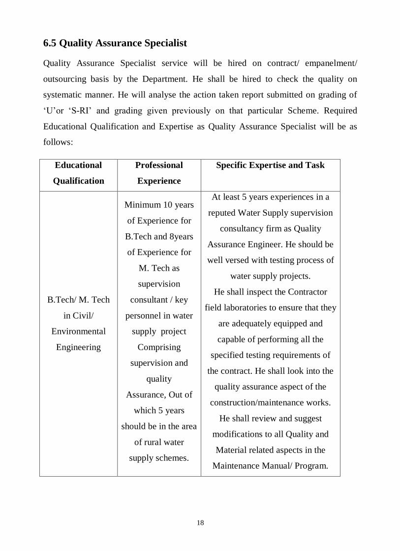
6.5 Quality Assurance Specialist
Quality Assurance Specialist service will be hired on contract/ empanelment/
outsourcing basis by the Department. He shall be hired to check the quality on
systematic manner. He will analyse the action taken report submitted on grading of
‘U’or ‘S-RI’ and grading given previously on that particular Scheme. Required
Educational Qualification and Expertise as Quality Assurance Specialist will be as
follows:
Educational
Qualification
Professional
Experience
Specific Expertise and Task
B.Tech/ M. Tech
in Civil/
Environmental
Engineering
Minimum 10 years
of Experience for
B.Tech and 8years
of Experience for
M. Tech as
supervision
consultant / key
personnel in water
supply project
Comprising
supervision and
quality
Assurance, Out of
which 5 years
should be in the area
of rural water
supply schemes.
At least 5 years experiences in a
reputed Water Supply supervision
consultancy firm as Quality
Assurance Engineer. He should be
well versed with testing process of
water supply projects.
He shall inspect the Contractor
field laboratories to ensure that they
are adequately equipped and
capable of performing all the
specified testing requirements of
the contract. He shall look into the
quality assurance aspect of the
construction/maintenance works.
He shall review and suggest
modifications to all Quality and
Material related aspects in the
Maintenance Manual/ Program.

19
6.6 MIS Specialist
MIS Specialist service will be hired on contract/ empanelment/ outsourcing basis by
the Department. He shall be hired to monitor projects sanctioned under the
programme and progress in terms of physical, financial targets and against overall
monitoring parameters. Also shall look after the IT systems developed or to be
developed by the department.
Educational
Qualification
Professional
Experience
Specific Expertise and Task
B. Tech/M.Tech
in Computer
Engineering/
Information
Technology
Minimum 5
years of
Experience in
IT sector with
B. Tech and 3
years
experience
with M.Tech
degree
She/he should have proven experience in
design and development of application
modules, hosting of applications, system &
data integration and review of existing IT
systems. Strong communications, time
management and multi tasking skills.
7.0 Quality Control Mechanism
7.1 1st Tier Quality Control Mechanism
The PIU will the first tier, whose primary responsibility will be to ensure that all the
materials used and the workmanship conform to the prescribed specifications. As the
first tier, the PIU will supervise the site quality laboratory to set up by the contractor
as per contract. It shall also ensure that all tests prescribed are carried out at specified
time and place by the specified person of the PIU.
20
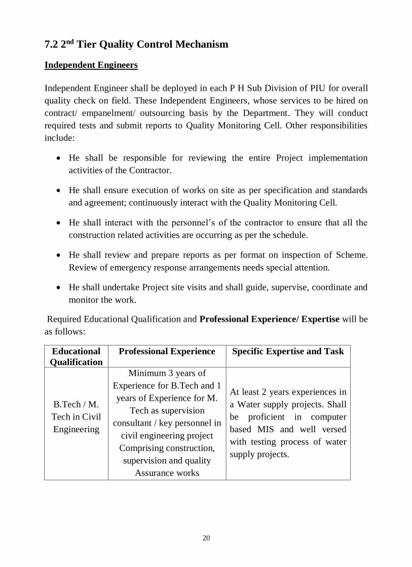
7.2 2nd Tier Quality Control Mechanism
Independent Engineers
Independent Engineer shall be deployed in each P H Sub Division of PIU for overall
quality check on field. These Independent Engineers, whose services to be hired on
contract/ empanelment/ outsourcing basis by the Department. They will conduct
required tests and submit reports to Quality Monitoring Cell. Other responsibilities
include:
He shall be responsible for reviewing the entire Project implementation
activities of the Contractor.
He shall ensure execution of works on site as per specification and standards
and agreement; continuously interact with the Quality Monitoring Cell.
He shall interact with the personnel’s of the contractor to ensure that all the
construction related activities are occurring as per the schedule.
He shall review and prepare reports as per format on inspection of Scheme.
Review of emergency response arrangements needs special attention.
He shall undertake Project site visits and shall guide, supervise, coordinate and
monitor the work.
Required Educational Qualification and Professional Experience/ Expertise will be
as follows:
Educational
Qualification
Professional Experience Specific Expertise and Task
B.Tech / M.
Tech in Civil
Engineering
Minimum 3 years of
Experience for B.Tech and 1
years of Experience for M.
Tech as supervision
consultant / key personnel in
civil engineering project
Comprising construction,
supervision and quality
Assurance works
At least 2 years experiences in
a Water supply projects. Shall
be proficient in computer
based MIS and well versed
with testing process of water
supply projects.

21
7.3 3rd Tier Quality Control Mechanism
Principal Quality Monitors
The Principal Quality Monitors, who are the third tier in Quality Control, play a vital
role in overseeing the Quality of the Project works.
Inspection by PQMs:
The PQMs shall be given the programme in advance to inspect the works in
designated districts of the state in a particular month. The process to be followed is as
follows:
The PQMs will be sent the letter of request in hard form as well as through E-
mail with programme of inspection of works. The copy of the same shall also
be marked to the concerned PIU.
The details of schedule of visit will be made available on website as well as in
the mail in the last week of the preceding month to enable the PQMs and PIUs
to make necessary arrangements.
The programme of inspection is valid for the inspection of works for the
month mentioned in letter of request; therefore, in no case the inspection
should spill over to the next month.
It will be the responsibility of the QMC to ensure adequate arrangements for
inspection by the PQM, including ensuring the supply of desired information to PQM
by PIUs.
The selection of Scheme to be visited by PQMs in a particular district shall be
provided by QMC through computerised random sampling basis. Once the project is
selected, the PIU shall provide the necessary information in respect of the project and
also have to ensure that all the information in regards to the selected scheme is
updated in online monitoring portal.
Document to be provided to PQMs by PIU:
Copy of DPR along with drawings of the work proposed to be inspected.
Quality Control Registers to enable PQM to enable PQM to understand the
details of tests conducted.
Essential equipments and manpower to be provided to PQM to conduct some
hand feel tests and field test under this personal supervision.

22
With a view to achieve uniformity, objectivity in observations and evaluation,
the method of observations and evaluation has been standardised for all the
tiers of Quality Management.
The PQM has to traverse the entire Scheme. While making observations, the PQM
must keep in mind that the intention is to improve and strengthen the system to
achieve overall project quality. As such, the PQM would also focus on project
management by the PIU and make his observations.
Post Inspection Discussion
During inspecting the Schemes, the PQM should hold an informal meeting with the
PIU officers and Contractor’s representatives / engineers in order to review the
findings of the inspection and to suggest improvements in execution to obtain better
Quality for all other works under the PIU.
Submission of Inspection Report by PQM and Action by PIU
a. After the inspections in the District are over and copy of reporting format in
hard form will be handed over by the PQM to the PIU and also enter the same
in online mode in the monitoring portal so that they can be accessed by
Quality Management Cell.
b. It is open to the PQM to discuss the specific issues arising from the Scheme
inspection with the head of the PIU. Unless the PIU disagrees with the
conclusion/ recommendations, rectification work should be ordered
immediately by the PIU. In case the head of the PIU feels that any portion of
the Inspection Report or the suggested rectification is not appropriate he shall
make a full report to the Quality Management Cell.
It is to note here that minimum nos. of inspections per day to be carried out by any
PQM shall not be less than 2 schemes.

23
8.0 Budget for Proposed Quality Monitoring System
SL.
No. Position/ Items Nos.
Amount
(In Rs)
Cost for
one Year
Total Cost per
Year (In Rs)
1 Independent Engineer
Honorariums
(125Nos@1 per P H Sub
Division)
125 125Nos. @ 60000.00 per
month 125*60000*1
2 9,00,00,000.00
Data management Cost 125 125Nos.@Rs. 500 per
month 125*500*12 7,50,000.00
2
PQM
(21nos.@1 per 2 P H
Divisions/PIU)
Assuming 15 days inspection per month per PQM
Honorarium per day @
3500.00 21
21Nos. for 15days
@Rs.3500per day 1102500*12 1,32,30,000.00
Lodging and Daily
Allowance 21Nos. for 15days @Rs.3000per day
945000*12 1,13,40,000.00
Data management Cost 21 21Nos.@Rs. 500 per
month 10500*12 1,26,000.00
3 Quality Assurance
Specialist 1
1No.@Rs. 80000 per month
80000*12 9,60,000.00
4 MIS Specialist 1 1No.@Rs. 60000 per
month 60000*12 7,20,000.00
5 Other Supporting Staff
for QMC 10
10 No.@Rs. 10000 per month
100000*12 12,00,000.00
6 Logistic Support for
QMC LS Rs. 1500000 per month 1500000*12 1,80,00,000.00
Sub Total (Rupee Thirteen Crore Sixty Three Lac and Twenty Six
Thousand only) 13,63,26,000.00
FOR SOFTWARE DEVELOPMENT
6
Development of Software
along with maintenance
for 5 years ( On one time
basis)
- 3000000.00 - 3000000.00
Sub Total (Rupee Thirty Lac only) 3000000.00
Total (Rupee Thirteen Crore Ninety Three Lac and Twenty Six
Thousand only) 13,93,26,000.00

24
9.0 Web Based Online Monitoring System
Computerisation of data has the advantage of reliable storage, easy retrieval,
immediate processing and complicated calculation ability useful in generating high
level abstracted information for use in management. The advantage of a Centralised
database is that the range of comparison is not only vertical in terms of the time
period but also horizontal in terms of geographic spread across Districts and States. If
to this is added the facility of being able to access the data anywhere/anytime through
a web-based system, the utility and transparency is multiplied manifold, enabling an
extremely high level of project management and monitoring.
The SQMS (State Quality Management System) software shall be designed
especially for the entire scheme being executed by the department as an online web-
based system with centralised database and the principles underlying the operational
management of the software shall be as follows:
Data entry will be done at the point where data will be generated i.e. at the PIU
level for project data and at the IE , PQM and QMC level where their
intervention contributes value addition to the data.
The data entry shall be near real-time to enable outputs to be useful for
management as well as monitoring. This implies that the data entry shall be
closely parallel the actual work process and to ensure this, system checks will
be in place to ensure that the data precedent is on-line before processing for the
next step is done.
Since data entry may involve some extra effort, it must be seen to be
sufficiently advantageous. This involves building in the ability to generate
MIS outputs closely resembling or better than existing manually generated
outputs and dispensing with manually generated outputs and attendant labour.
The full power of the software is to be brought to bear to generate outputs
useful at all levels – monitoring and management output at PIU levels,

25
progress management and management-by-exception outputs at IE/PQM level
and abstracted and analysed information policy and overall management
information for use in QMC.
Transparency will be inbuilt in the system enabling abstracted data to be
drilled down to the basic data, generally ‘Habitation’.
9.1 Online Monitoring Responsibilities
Effective monitoring of the Programme being critical, the QMC must ensure that all
aspects of the rural water supply programme in the State are systematically
monitored and feedback used for correcting deficiencies. The Online Management &
Monitoring System to be developed shall be the chief mechanism for monitoring the
Programme. Officials managing the various aspects of the programme are required to
furnish online all the data in respect of scheme details and transactions carried out by
them in the relevant module of the Online Monitoring System.
The SQMS shall consist of the following main modules:
Master data Module: - Master data includes the following
Area master which contains data regarding the villages/Habitations and
details of facilities available at habitation level (To be entered at PIU
level).
Scheme master which includes details regarding the name of the
scheme, type etc. (To be entered at PIU level).
MP/MLA Constituency (To be entered at PIU level).
Contractor details (To be entered at PIU level).
Execution & Monitoring Module
Entry of progress against each work in physical and financial terms (to
be entered at PIU level).
Completion of project works (to be entered at PIU level).
Maintenance Module: -Physical and financial data regarding contract-based
maintenance (to be entered by PIU level).

26
Quality Monitoring –Data Regarding QC inspection carried out by IEs &
PQMs is to be entered. The monthly schedule of inspection of IE and PQM
shall also enter on website.
10.0 Operating the State Quality Management System
The QMC shall hire the services of MIS specialist on contract/ outsource basis
having adequate knowledge and experience of Information Technology to function as
the Nodal Officer for managing the system. His function will be to oversee the
regularity and accuracy of the data being furnished by the PIUs. The Nodal Officer
shall also be responsible to oversee the upkeep of the Hardware and Software as well
as the training requirements of the personnel dealing with the program. He shall
maintain close liaison with the software developers and related parties for ensuring
hassle free running of the management system.
The QMC will ensure provision of necessary manpower, space and facilities to set up
the Computer Hardware at the District and Head Quarter (HQ) Level apart from
ensuring regular and timely feeding of data. Since most of the data would reside on
the central server located at HQ, so the Nodal Officer will ensure that the central
server is functional all 24 hours of the day.
The main function of the Nodal officers will accordingly include the following:
Ensuring proper management of the central server, including its functioning,
maintenance, data backup, and connectivity.
Overseeing the proper management of the computer system at PIU level,
including their functioning, maintenance, connectivity etc.
Monitoring the progress of data entry at PIU level and apprising the superior
authorities of the QMC of persistent delays/failure to update data.
Supervising bulk data entry, management of data entry operator deployment
etc.

27
Monitoring effectiveness of online connectivity status of PIU computers,
devising and implementing solutions for better and more secure connectivity.
Coordination with the QMC for ensuring updating of inspection data on the
SQMS.
Ensuring integration of data and applications with similar or complementary
applications.
Printing out monthly/quarterly MIS outputs and submitting them to the
Principal Secretary/ Secretary and Engineer in Chief PHED along with his
comments.
Training needs assessment.
The Executive Engineer (Head of PIU) is pivotal to the successful operation of the
SQMS and the QMC shall hold him personally responsible in case of persistent
failure to keep the data updated. The Executive Engineer shall be responsible for:
Ensuring proper management of the PIU computers and peripherals including
the software, data backup etc.
Enforcing an Annual Maintenance Contract (AMC) for the computer system.
Ensuring internet connectivity.
Managing the offline software and uploading of data in case of poor internet
connectivity.
Printing monthly quarterly MIS outputs and forwarding them to the Nodal
officer along with his comments on the reliability of the data.
System Checks under SQMS
In order to ensure accuracy of information at all times, system checks will be placed
in the software and it is necessary therefore that data entry is accurately,
systematically and regularly done into the system.

28
11.0 Inspection, Reporting Output & Analysis
(For Tier 2 & 3 )
Progress of Work: For monitoring the physical and financial progress of the works
at PIU level, the QMC will devise suitable mechanisms. The formats for monitoring
of the progress shall be prescribed in such a way that the quarterly and monthly
information required at HQ could be easily extracted out.
Implementation of Contracts: Monitoring of work under the contracts shall form
an important element of the contract management. Time and quality is the essence of
the Contract and therefore, these items shall be monitored by the PIU on a regular
basis. The QMC shall devise a suitable mechanism for monitoring of the following
aspects of the Contract at QMC level:
Time Control: Suitable formats shall be prescribed. The PIU will be
required to furnish phase-wise information regarding delay in execution
of works to QMC. To monitor the action taken in respect of works
delayed beyond 90 days the PIU will be required to furnish information.
Quality Control: Once the field laboratories are established, it would
be responsibility of the contracting agency to maintain Quality Control
Register.

29
11.1 Quality Control Checklist
Sr. No. Attribute Available Grade
I Quality Control Arrangements S/S-RI/U
II Material S/S-RI/U
Coarse aggregate (for individual structure of RCC
works more than 25 M3)
Fine aggregate (for individual structure of RCC works
more than 25 M3)
Diameter and dimension of steel bars/angles/ channels/
plates as per BIS specification
HDPE/MDPE/CPVC/CI/DI/GI/MS/UPVC etc. Pipes
(Physical verification, Dimensions check and
verification of 3rd party inspection report)
Valves/ Specials/ Flow Meter/ Pressure Gauge/ Bib Cock as
per specification mentioned in Bid Document.
III Installation ,Testing and Commissioning of High Yield
Tube wells S/S-RI/U
Screen/Slotted, Blank and Housing Pipes (Physical
verification, Dimensions check)
Pea Gravel size & quantity /quality
Drilling Bits sizes and Drilling Rods lengths
Drilling of Bore well [ Dia. as per drawing IS : 2800 (Part-
1)] preparation of Strata Chart / Well logging
Installing the casing and well screen as per strata chart
Ensure sand-free operation at maximum yield (Quality &
Discharge)
Availability of Strata Chart
IV Installation ,Testing and Commissioning of Pumping
Sets S/S-RI/U
Pump Sets as per specifications
Accessories like panel board, Switch Gear, Starter, Relay &
Capacitors of the pump sets are provided as per
specification.
V Installation ,Testing and Commissioning of Water
Treatment Plants S/S-RI/U
CSIR Technology/Treatment Technology approved by

30
CSIR or endorsed by GoI- Certificates
FRP / MS/ Vessels as per provisions in Bid Document
Treatment Media (Check third party inspection report)
Control Valves/ SCADA System (As per provisions in the
Bid Document)
Performance of Treatment Unit
Quality of Water in distribution system (As per BIS 10500)
and residual chlorine at consumer end
VI Civil Works: Staging for Water Storage Structure,
Installation of PVC Storage Tank and Construction of
Pump House & Toilet.
S/S-RI/U
A Foundation (As per design and specification)
B Concrete Works
Concrete Mixer used
Vibrator used
C Masonry
Bricks soaked in water before use
Proper jointing of Masonry Works
D RCC Works
Checking of centering before placing reinforcement
Checking of Reinforcement before concreting
Pouring of Concrete
Collection and testing of concrete cube samples as per BIS
Water proofing of roof slabs
Curing
E Plastering
Quality of Plastering
Curing
F Steel Staging for Water Tanks S/S-RI/U
Gusset Plate Fixing to foundation bolt
Column Joist/Channel fixing to Gusset Plate
Diagonal Angle fixing to Gusset Plate
Water tank Platform Beam (Joist/Channel) fixing to column
Water tank Platform Sheet fixing to Beam

31
Anti Corrosive painting on staging structure
G Rotational Moulded Polyethylene Water Storage Tanks S/S-RI/U
BIS marking
Cylindrical Vertical Tanks placing on staging is proper
Inlet and Outlet pipe of suitable Diameter
Outlet and Drain pipe of suitable Diameter
VII Laying, Testing and Commissioning of pipes, specials
and other related works for Distribution Network S/S-RI/U
Layout as per approved construction drawings
Trench as per the alignment, depth, minimum cover
Identification of leaks, cracks & damages in MDPE Pipe
Specials like bends, tees, valves confirming to relevant BIS
Proper jointing of pipes
Thrust Blocks provided at bends
Proper backfilling
Air Valves conform to pipe line requirement
Non-return valves conform to the pipe line requirements
Pressure release valves conform to the pipeline
requirements
Interconnection with source of supply
Pressure adequacy at tail end
VIII Providing House Connections S/S-RI/U
All households provided connections
Quality of Bib Cock at household level
Adequacy of pressure at user tap
Any unserved household
Pollution or scope of pollution in Drinking water
House connection and stand post as per specification
Identification of leaks, cracks & damages in MDPE Pipe
IX Trial –runs of the scheme and water quality testing of
5% of total House Hold Connection S/S-RI/U
Test certificate of water quality from authorized
laboratories
32
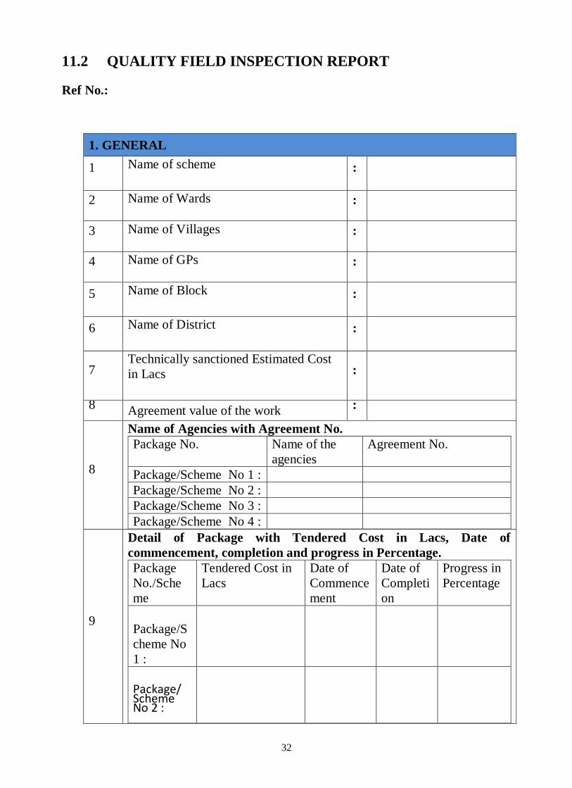
11.2 QUALITY FIELD INSPECTION REPORT
Ref No.:
1. GENERAL
1 Name of scheme
:
2 Name of Wards
:
3 Name of Villages
:
4 Name of GPs
:
5 Name of Block
:
6 Name of District
:
7 Technically sanctioned Estimated Cost
in Lacs
:
8 Agreement value of the work :
8
Name of Agencies with Agreement No.
Package No. Name of the
agencies
Agreement No.
Package/Scheme No 1 :
Package/Scheme No 2 :
Package/Scheme No 3 :
Package/Scheme No 4 :
9
Detail of Package with Tendered Cost in Lacs, Date of
commencement, completion and progress in Percentage.
Package
No./Sche
me
Tendered Cost in
Lacs
Date of
Commence
ment
Date of
Completi
on
Progress in
Percentage
Package/S
cheme No
1 :
Package/ Scheme No 2 :

33
Package/ Scheme No 3 :
10 Name of Circle
:
11 Name of Division
:
12 Name of Sub-division
:
13 Name of S.E
:
14 Name of E.E
:
15 Name of S.D.O.
:
16 Name of J.E
:
17 Name of Chairman of GPWSC
:
18 Scheme Inspected by C.E with date/
reference
:
19 Scheme Inspected by S.E with date/
reference
:
20 Scheme Inspected by E.E with date/
reference
:
21 Scheme Inspected by E.E (QMC) with
date/ reference
:
22 Date of field inspection
:
34
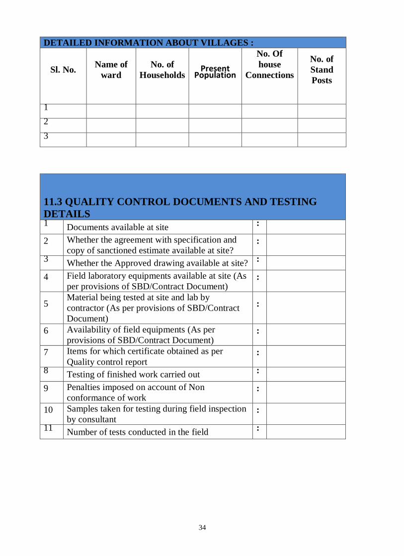
DETAILED INFORMATION ABOUT VILLAGES :
Sl. No.
Name of
ward
No. of
Households
Present Population
No. Of
house
Connections
No. of
Stand
Posts
1
2
3
11.3 QUALITY CONTROL DOCUMENTS AND TESTING
DETAILS 1
Documents available at site :
2 Whether the agreement with specification and
copy of sanctioned estimate available at site? :
3 Whether the Approved drawing available at site?
:
4 Field laboratory equipments available at site (As
per provisions of SBD/Contract Document) :
5 Material being tested at site and lab by
contractor (As per provisions of SBD/Contract
Document)
:
6 Availability of field equipments (As per
provisions of SBD/Contract Document) :
7 Items for which certificate obtained as per
Quality control report :
8 Testing of finished work carried out :
9 Penalties imposed on account of Non
conformance of work :
10 Samples taken for testing during field inspection
by consultant :
11 Number of tests conducted in the field
:

35
11.4 AVAILIBILITY OF SITE DOCUMENT
Sl.
No
Description
Availability at site
Yes / No/ NR
Remarks
1 Site Order book
2 Material Register
3 Daily Progress Report.
4 Concrete pour Record
5
Design and Drawing
Record
6 Non Conforming Item
Record
11.5 FIELD LABORATORY EQUIPMENT AVAILABLE AT SITE
(As per provisions of SBD/Contract Document)
Sl. No Description
Availability at site
Yes / No/NR
Remarks
1 Compression testing
machine
2 Sieve set complete
3 Measuring jars
4 Screw gauge
5 Vernier calliper
6 Balance
7 Slump cone
8 Cube mould 2 sets. In
conformance to ISI
9 Hydraulic testing machine

36
11.6 MATERIAL/ WORKS TESTED BY CONTRACTOR (FIELD
LABORATORY) (As per provisions of SBD/Contract Document)
Sl.
No
Name of material
Qty
used
Date of
test
Result
Satisfactory/ Unsatisfactory
Remarks
1 Sieve analysis of
Coarse aggregate
2 Sieve analysis of
Fine aggregate
3 Bricks
4 Cement
5 Reinforcing Bar
6 Water
7 Mortar
8 Slump Test
9 Cube test for
Concrete
10 UPVC pipe for w/s
11 S.W. pipe
12 R.C.C. pipes
13
G.I. ,HDPE, MDPE,
CPVC, CI, DI, GI,
MS, UPVC
14
Hydraulic Pressure
test of water supply
pipelines

37
11.7 EQUIPMENTS/ T&P AVAILABLE AT SITE (As per provisions
of SBD/Contract Document)
Sl.
No.
Equipment
Availability Yes /
No/NR
Remarks
1 Mixture Machine with standby
arrangement
2 Vibrator with standby arrangement
3 Lifting pump for curing
4 Levelling instrument
5 Hoisting lift
6 Jack Hydraulic jointing mechanism for
160mm and above dia (HDPE pipes and
fittings)
7 Butt fusion heater with control box for
HDPE pipe up to 140 mm dia.

38
11.8 DETAILS OF MANUFACTURER/3rd PARTY INSPECTION
CERTIFICATES (As per provisions of SBD/Contract Document)
Sl.
No.
Description Qty. used
MC
availability Yes / No/
NR
Acceptability By
Department
Remarks
1 Cement
2 Steel for
Reinforcement
and structural steel
3
Pipe such as G.I.
,HDPE, MDPE,
CPVC, CI, DI, GI,
MS, UPVC
4 AC/GI/Fiber glass
sheets
5 Electrical
cables/fans and
fixtures
6 Switches/sockets
and boards
7 Flow measuring
devices
8 Control Panel
9 Lightening
arrestor
10 Water Level
indicator and
controllers.
11 Disinfection Units
12 Pump and Motor
13
Pipe such as G.I.
,HDPE, MDPE,
CPVC, CI, DI, GI,
MS, UPVC
14
All types of valves
such as sluice
valve, Air valve
etc.
15 Treatment unit

39
11.9 DEPARTMENTAL TEAM INSPECTION AT
MANUFACTURING PREMISES (As per provisions of SBD/Contract
Document)
Sl.
No.
Description
Date of
inspection
Name
of
officers
Acceptability Yes / No/NR
Remarks
1
Pipes such as DI,
CI, PVC, MS,
SW,
HDPE/MDPE,
etc.
2 Pumps, Motors &
D.G. Sets
3 Treatment Unit
11.10 PENALITIES ON A/C OF NONCONFORMANCE OF WORK
Sl.
No.
Name of
work/Material
Test
Results
Qty. of
material
rejected
Amount
of
Penalty
if
accepted
Remark
Actual
Standard
1
2
3
4
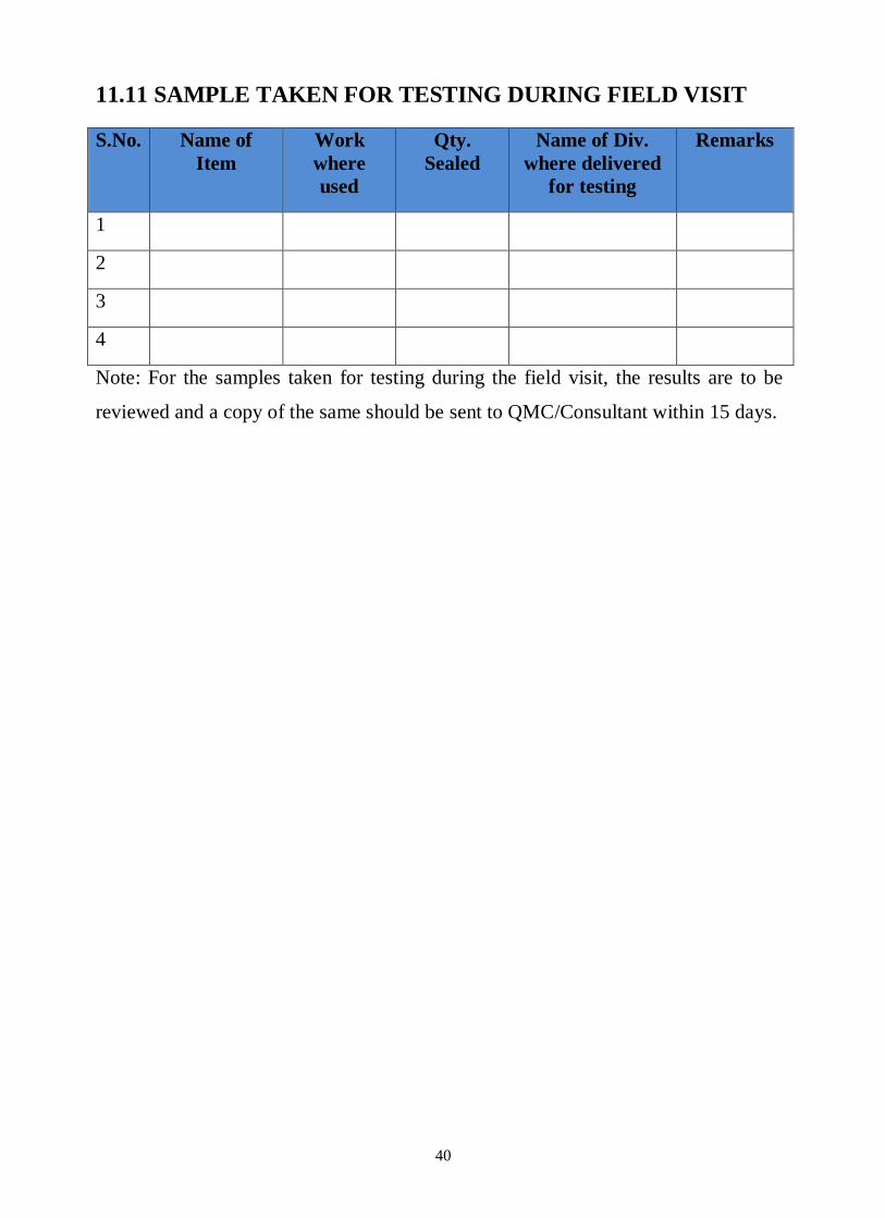
40
11.11 SAMPLE TAKEN FOR TESTING DURING FIELD VISIT
S.No. Name of
Item
Work
where
used
Qty.
Sealed
Name of Div.
where delivered
for testing
Remarks
1
2
3
4
Note: For the samples taken for testing during the field visit, the results are to be
reviewed and a copy of the same should be sent to QMC/Consultant within 15 days.

41
11.12: TEST CONDUCTED BY INSPECTION TEAM (As per
provisions of SBD/Contract Document)
S.No. Name of
Item
Location Type of test Standards %
Passing
Remarks
1 Coarse
Aggregate
(Applicabl
e for
Service
Reservoir)
Sieve
analysis
2 Fine
aggregate
(Applicabl
e for
Service
Reservoir)
Sieve
analysis
Silt content
3 Steel
IS:1786
Dia.
Wt. / M in
Kg
4 UPVC/MD
PE/CPVC/
CI/DI/GI/
MS/UPVC
pipes
OD
Min.
Max.
Wall
Thickness
Make
5 Bricks Color
Length(mm)
Width
Height
Comp.
strength
6 Barbed
wire A-1
Gauge (mm)
Mass
(gm/m)
7 M.S Pipe
NB
Thickness

42
NB
Thickness
8 Screen pipe NB
Thickness
9 Floor
Thickness
10 Plaster
Thickness
11 Door
Thickness
12 Roof slab
Thickness
13 M.S Girder
Size
14 Angle iron
Pickets
Size
Thickness
15 LDPE
Sheet
Thickness
16 Cube test
M15
M20
M25
Compressive
strength
Compressive
strength
Compressive
strength
17 Slump test
Slump in
mm
18 Cement
Grade
Date of
Manufacture
Fineness

43
CONSTRUCTION QUALITY
CONTROL/ASSURANCE
MANUAL

44

45
12.0 INTRODUCTION
This Manual prepared for the use of Public Health Engineering Department, Government of Bihar
is based on Various Quality Assurance practices, PWD specifications, and requirement of the
tender document for test of materials, Field /laboratory testing and relevant IS: codes. This is a base
document outlining policy, procedure, responsibilities, compliance acceptance criteria and
documentation for carrying out tasks related to inspection, testing and reporting on various
materials, construction items involved for the satisfactory completion of the work. Quality
Assurance & Quality Control (QA/QC) Manual provides a guide lines for supervision of
construction project. A QA/QC Manual establishes a standard guideline for enabling supervisory
staff to check different activities of construction in respect of technical specifications. Quality
assurance plan serve as a road map to supervisory staff to ensure quality of project works.
12.1 Back Ground:
Public Health Engineering Department (PHED) is the nodal department for designing,
planning, monitoring of Water Supply Schemes with operation & maintenance of its erection. It has
overall responsibility of managing and monitoring of activities to enhance public health through
improved water supply facilities and services in rural habitations.
Bihar is the 13th largest and third most populated state with a total population of 10.38
crore with significant proportion of rural population (9.20 crore). It is also one of the most densely
populated state with 880 persons per sq km as against the national average of 324 (Census 2011).
The state has 38 districts, 532 blocks, 8741 gram panchayats and 107640 habitations. Bihar is
blessed with abundant surface and ground water resources and receives average rainfall of 1250 to
1350 mm. The water table during summer varies from as low as 5 m in the north eastern districts to
20 m in the southern districts.
Water Quality situation in Bihar:
Even after being rich in water resources, the drinking water is not safe in all villages and the
water quality mapping of the whole state indicates that the rural population is at risk due to its poor
water quality in pockets. Out of 38 districts, excess Arsenic contamination is found in some pockets
of 13 districts (Begusarai, Bhagalpur, Bhojpur, Buxar, Darbhanga, Katihar, Khagaria, Lakhisarai,
Munger, Patna, Samastipur, Saran & Vaishali). Excess fluoride contamination is also reported in
few pockets of 11 districts (Aurangabad, Banka, Kaimur, Bhagalpur, Gaya, Jamui, Munger,
Nalanda, Nawada, Rohtas & Sheikhpura). Munger & Bhagalpur are having both Arsenic and

46
Fluoride contamination issue. Iron is again reported in excess than its permissible limit (BIS
standard) in 9 districts (Araria, Begusarai, Katihar, Khagaria, Kishanganj, Madhepura, Purnea,
Saharsa & Supaul). Existing Drinking Water facilities available in Rural Bihar:
In order to overcome the above problem, the Govt. of Bihar with the support of Ministry of
Drinking Water & Sanitation (MDWS), Govt. of India has launched several water supply schemes in
rural areas consisting of Hand Pumps (Ordinary & India Mark II/III), Pipe Water Supply Schemes,
Solar powered Mini Pipe Water Supply Schemes and Multi village Pipe Water Supply Schemes etc.
Water ATMs and Jadoots (water purification units) have also been deployed in affected districts for
potable water supply to habitants. In addition, under seven Nischay of Govt. of Bihar, one of the
components is “Har Ghar Nal Ke Jaal” Yojna, through which each & every house hold in the water
quality affected habitations is going to get potable water supply with one tap connection.
As per the DDWS website of Govt. of India, out of total 110218 habitations existing in Bihar,
83.89 percent meet out their drinking water requirement through hand pumps and meagrely 4.32
percent are getting the facility through piped water supply. This is corroborated by the census of
India 2011 data. As per their report, 86.90 percent house-holds in Bihar depend on hand pumps and
only 4.4 percent receive pipe water. It is evident that rural Bihar continues to depend on ground water
for meeting its thirst. Therefore, quality of drinking water is a determining factor for a healthy and
prosperous life of the rural community in Bihar (Ref: Study report entitled “Assessment of
Functionality of Rural Drinking Water Supply Schemes in Bihar” submitted by XLRI, Jamsedpur in
2017).
12.2 QUALITY DEFINITION
Quality is the totality of features and characteristics of a product for service that bears on its ability
to satisfy the projects functional requirements. The quality of output is always agreed upon between
the supplier and the client (In project works, Contractor and the employer, respectively), and the
quality objective is to achieve zero defects with best quality of the project works. This is possible
only by ensuring quality control at every stage during progress of construction.
Quality is conformity to standards and requirements to achieve excellence. The following are some
definitions pertaining to quality and how to achieve it.
Quality control (QC): The operational techniques or a system of maintaining standards by
reviewing, checking, inspecting and testing.

47
Quality Assurance (QA): The planned and systematic actions and implementations
necessary to provide adequate confidence that the work will satisfy quality requirements.
Quality System (QS): A set of documented processes, which seek to provide satisfaction
that, the project outputs will fulfil all the requirements for which it is being planned. The
Quality System should fully incorporate the organization, human resources, materials,
equipments, processes, inspections, testing and other parameters of the project. A key
element of QS is the QA/QC Manual.
Quality Surveillance: This normally covers two aspects.
At the project level, a review is required to ensure that the quality practices are
implemented and documented to ensure in relation to the quality system.
At the contract package level, inspection and testing is required to ensure that the works
executed meet the required quality standards.
12.3 QA/QC MANUAL
This QA/QC Manual focuses on the implementation activities of the project following contract
award, primarily on supervision and quality control of construction works. The QA/QC Manual is
intended to be used as guide line for supervision of construction activities.
It will provide a base outline towards, procedure, responsibilities, compliance acceptance criteria
and documentation for carrying out inspection, testing and reporting on various materials, items
involved for the satisfactory execution of the project work. In all cases, somehow, it is most
important to understand that the technical specifications as specified in the contract document /
agreement are the guidelines for any construction activity.
The QA/QC Manual for the Construction activity does not attempt to suggest technical
specifications, since these are stated in the contract documents. Its aim is to ensure that the works
are executed as per specifications to achieve best results. Test results shall be interpreted as
applicable for individual package, in accordance with the technical specifications as specified in the
conditions of contract.
Key Parameters of Quality Assurance
Quality system involves the various key tools which are generally practiced in the field
for Quality Assurance System. The well designed quality assurance system will provide
confidence that the project outputs will fulfil all the requirements for which it is being
planned. The quality assurance system should have the following basic parameters.

48
Site documents
Mandatory and optional testing
Availability of field and departmental laboratories
Manufacturing/Third party inspection
Departmental team inspections
Checklist guide for works
Site inspections
Post quality testing of finished works
Quality certification
Monthly reporting and review meetings
12.4 Q A/Q C DUTIES
The contractor’s QA/QC duties are summarized in Table: 12.1. Apart from these, other duties shall
be performed as per the contract documents or directed by the Engineer. It is essential to keep
certain documents at site for making a permanent record of each and every item related to the
project. Such items may include tests conducted at site, test certificates, instructions issued to
contractor, record of drawings issued to the contractor, inventory of the material at site. All such
site documents play an important role not only in assuring the quality of the work, but also in
making the project management comparatively easier.
Table: 12.1 List Of Contractor’s QA/QC Duties
Activity/Item Contractor’s QA/QC Duties.
Designs/Drawings
for contract
Maintain design / drawing register at site
Use only approved drawings for construction
Test laboratory and equipment
Intimate the details, date of completion with requisite
manufacturer’s and calibration certificates of equipments.
Maintain the equipments in good condition and calibrate as
necessary.
Material receipts &
Material testing
Enter receipts in material register
Materials to be tested only in approved laboratories
Prepare concrete mix proportions as per volume as required by
contract and submit test results
Take test samples in presence of officials when requested

49
Perform material tests
Submit test reports to Department with monthly reports and
maintain test logs.
Rejected materials Tag and record all rejected materials
Intimate in writing the proposed date of removal of material from
site and confirm after removal
Material
Consumption
Enter daily consumption of materials in material register and
indicate balance quantity
Construction
Equipment
Intimate the department, date of mobilization along with requisite
insurance certificate
Maintain equipment in good working condition
Intimate breakdown of construction equipment.
Construction Intimate department in writing when construction is going to
commence and what activities are proposed to be undertaken.
Intimate department in advance when critical works, such as
installation of treatment unit, concreting, embankment, paving,
pipeline laying and jointing, testing, etc., would be undertaken,
along with the test certificates of the materials proposed to be used
in these works. No critical activity shall start unless the material is
tested. Certificates are verified and approved by the concerned
officer.
Concreting to take place only after pour card is signed.
To provide any other QA/QC requirement.
Daily Work Progress To maintain daily log.
Testing works in
progress
Perform tests as per contract requirements
Submit test reports to department.
Maintain test log during execution of works
Rejected work items Rectify defective work and invite for re inspection
Progress scheduling
and control
Prepare and maintain project schedules and undertake work in
accordance with approved schedule.
Reporting Prepare and submit Monthly Progress Reports and other reports as
per contractual requirements.
Records Maintain the following records on Site/Contractor’s
Office/Laboratory

50
Workmanship All the work executed against the contract shall be of good
workmanship.
Disposal of Debris All the Debris should be disposed of properly after completion of
construction work.
12.5 QUALITY ASSURANCE BY DEPARTMENTAL ENGINEERS
DURING INSPECTION
The tenders are on turnkey basis and all the material is procured by the contractor, hence to have a
proper quality control and to improve the quality of work, the departmental engineers at various
levels will ensure the key parameters of quality assurance during inspections as per Table 12.2.
Table : 12.2 Quality Assurance By Departmental Engineers During
Inspection (As per provisions of SBD/ Contract document)
Sl. No Key parameters of Quality Assurance SE EE AE/JE
1 SITE DOCUMENTS
1.1 Site Order book
1.2 Material Register
1.3 Daily Progress Report. - -
1.4 Concrete pour Record -
1.5 Test Record
1.6 Design and Drawing Record -
1.7 Non Conforming Item Record
-
1.8 Cube test record
2
TEST REPORTS AS PER PROVISIONS
OF BID DOCUMENT
2.1 Cement -
2.2 Fine aggregate -
2.3 Coarse aggregate -
2.4 Concrete ( Slump, Cube test) -
2.5 Steel bars -
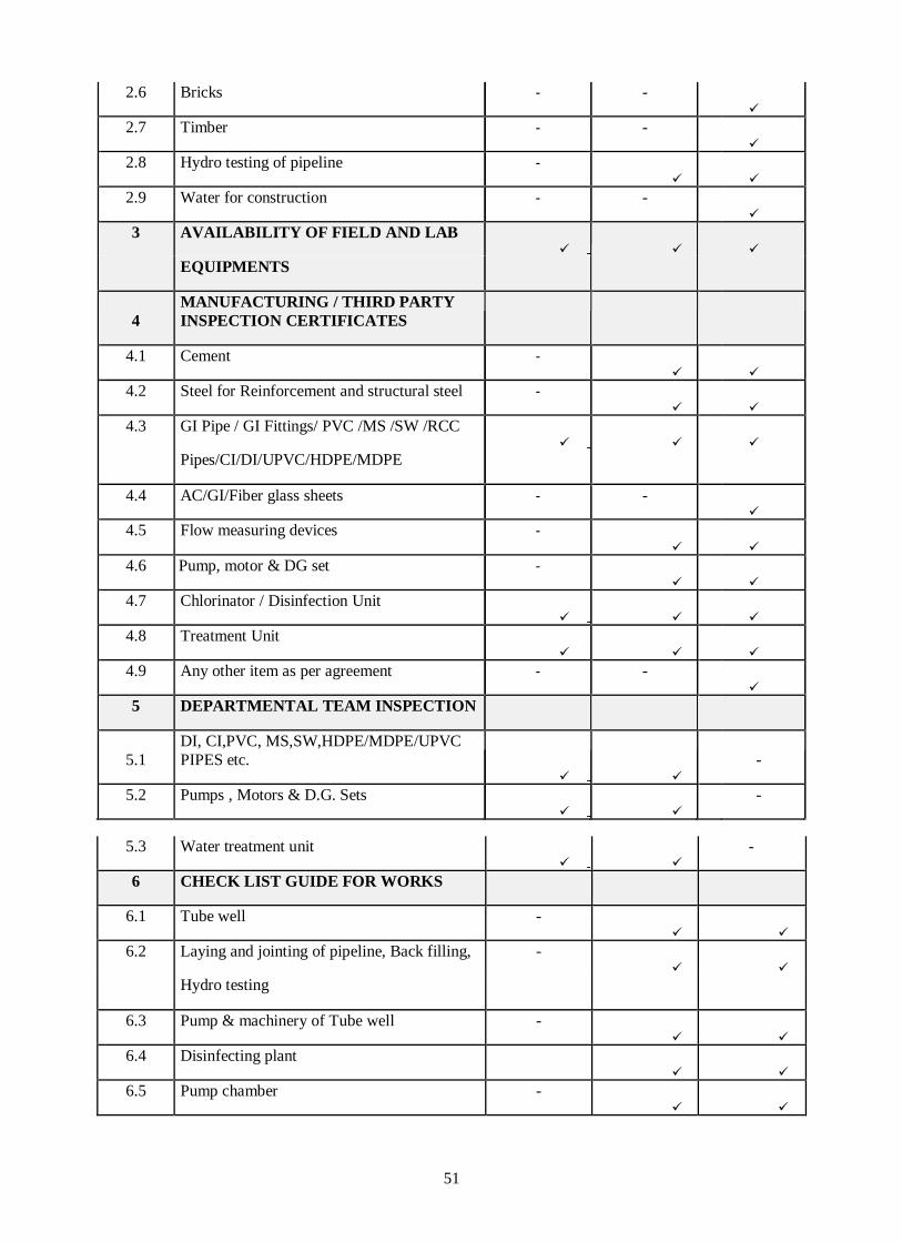
51
2.6 Bricks - -
2.7 Timber - -
2.8 Hydro testing of pipeline -
2.9 Water for construction - -
3 AVAILABILITY OF FIELD AND LAB
EQUIPMENTS
4
MANUFACTURING / THIRD PARTY
INSPECTION CERTIFICATES
4.1 Cement -
4.2 Steel for Reinforcement and structural steel -
4.3 GI Pipe / GI Fittings/ PVC /MS /SW /RCC
Pipes/CI/DI/UPVC/HDPE/MDPE
4.4 AC/GI/Fiber glass sheets - -
4.5 Flow measuring devices -
4.6 Pump, motor & DG set -
4.7 Chlorinator / Disinfection Unit
4.8 Treatment Unit
4.9 Any other item as per agreement - -
5 DEPARTMENTAL TEAM INSPECTION
5.1
DI, CI,PVC, MS,SW,HDPE/MDPE/UPVC
PIPES etc.
-
5.2 Pumps , Motors & D.G. Sets
-
5.3 Water treatment unit
-
6 CHECK LIST GUIDE FOR WORKS
6.1 Tube well -
6.2 Laying and jointing of pipeline, Back filling, -
Hydro testing
6.3 Pump & machinery of Tube well -
6.4 Disinfecting plant
6.5 Pump chamber -
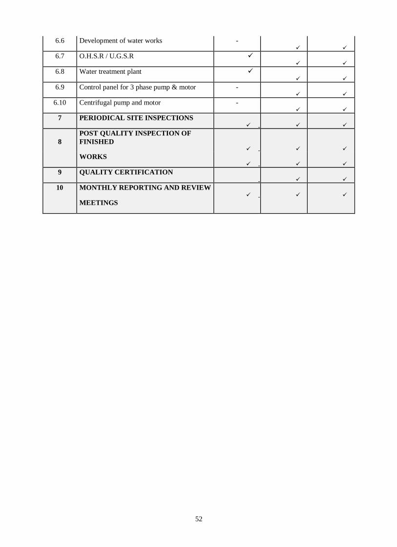
52
6.6 Development of water works -
6.7 O.H.S.R / U.G.S.R
6.8 Water treatment plant
6.9 Control panel for 3 phase pump & motor -
6.10 Centrifugal pump and motor -
7 PERIODICAL SITE INSPECTIONS
8
POST QUALITY INSPECTION OF
FINISHED
WORKS
9 QUALITY CERTIFICATION
10 MONTHLY REPORTING AND REVIEW
MEETINGS

53
13.0 CONSTRUCTION QUALITY CONTROL
This section provides an overview of construction quality control activities, including testing and
site inspection.
13.1 INTRODUCTION
Construction Quality Control (CQC) is intended to provide a comprehensive, common and
consistent framework for quality control across various contract packages. CQC comprises two
main elements of quality control:
Testing: Shall cover the types of tests to be carried out, frequency of testing and stage of
testing.
Inspections: covers the timing of inspections, what to be inspected and the inspection
procedures.
CQC should be affected at four stages:
Input Materials and Equipment Components
In-process Activities
Stage Completion
Interfacing (of special importance in water contract packages)
Final completion
13.2 TESTING
Various field tests on materials and works are required to be carried out by the contractor during
construction. A well-equipped and properly operating field test laboratory is an important feature of
quality assurance plan. A list showing typical testing equipment to be provided in the contractor’s
site laboratory is presented in Table 13.1. It should be made mandatory as per provision in the
technical/contract bid.

54
Table: 13.1 List of Equipment Required For Testing
Sl. No. Equipments Purposes
1 Compression testing machine Cube and brick
2 Sieve set complete Aggregates
3 Measuring jars Silt
4 Slump cone Workability
5 Cube mould 2 sets. Testing of C.C.
6 Screw gauge Thickness of pipes
7 Vernier calliper Dia. Of pipes
8 Balance Mass of pipe/steel etc
9 Hydraulic testing machine Testing of pipe
Laboratory equipment shall be properly calibrated, and certificates and its updating as and when
required should be kept at the laboratory for review by Department as necessary. Specialized
tests at outside laboratories shall only be undertaken with the prior approval of the Department.
Zonal laboratories one in each zone shall also be established for quality testing of materials used
by the contractor. The tests to be conducted in the Zonal laboratory are given in Table 13.2.
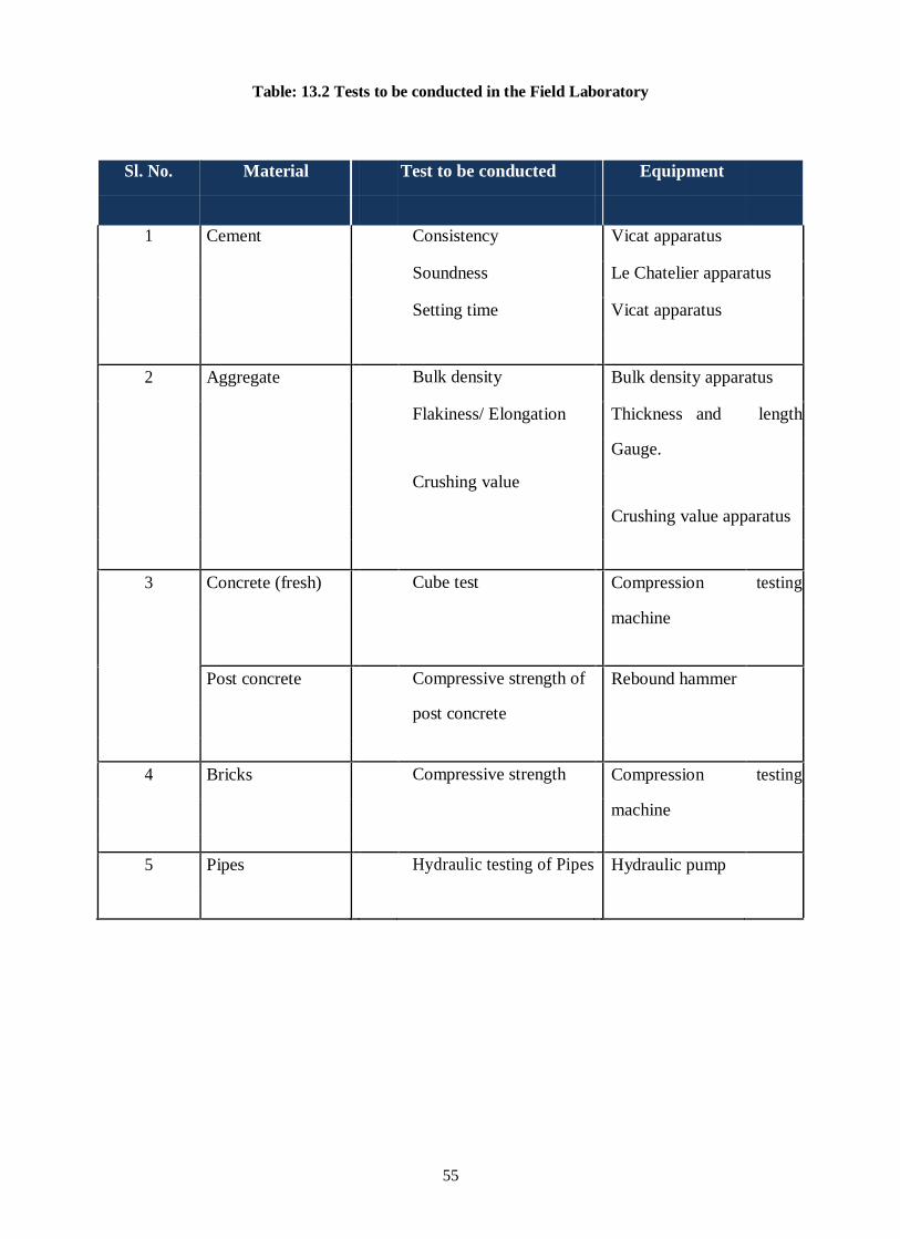
55
Table: 13.2 Tests to be conducted in the Field Laboratory
Sl. No. Material Test to be conducted Equipment
1 Cement Consistency Vicat apparatus
Soundness Le Chatelier apparatus
Setting time Vicat apparatus
2 Aggregate Bulk density Bulk density apparatus
Flakiness/ Elongation Thickness and length
Crushing value
Gauge.
Crushing value apparatus
3 Concrete (fresh) Cube test Compression testing
machine
Post concrete Compressive strength of Rebound hammer
post concrete
4 Bricks Compressive strength Compression testing
machine
5 Pipes Hydraulic testing of Pipes Hydraulic pump
56
13.3 INSPECTIONS OF SITES
Inspections of sites must be carried out to ensure that the construction activities and construction
materials conform to the relevant standards. Site inspections can be divided into everyday
supervision and periodical quality inspection. The suggestions in respect of these two have been
elaborated herein.
13.3.1 Everyday Supervision
Everyday site supervision of all construction activities shall be carried out by the Departmental
officers. This includes checking of lines, layouts and levels and other relevant checks. Daily
Progress monitoring shall also be carried out by the Supervising Team. The Supervising team
shall ensure that materials that have been rejected or for which a non- conformance report has not
yet been issued are not used in works.
Equipments to be used in construction is point of concern in quality assurance system. The
equipment requirements have been laid out in the Contract documents
Department involvement in the procurement of material will be limited to the extent that the
materials being used by the contractor should be checked visually from time to time for its quality
and to be associated during sampling and its testing.
13.3.2 Periodical Inspection for Quality
Periodic quality inspections during in-process, stage completion, interfacing and final completion,
and during all critical activities component wise as per the following examples in Table 13.3;

57
Table: 13.3 List Of Critical Activities Component Wise
Sl. No. Component Critical Activities
1 Pipe line Excavation
Completion of excavation Trenches for Pipe laying
Laying and jointing of pipes in correct alignment.
Pressure/leakage Testing of pipeline
Backfilling in layers and watering
2 OHSR/UGSR Centering and shuttering for R.C.C. works
Placing of reinforcing steel
Concrete mixing, vibrating and pouring
Testing for water tightness
Curing
3 Electro Mechanical Installation of electrical and mechanical equipments
such as Pump & Machinery and Disinfecting units etc.
Testing, trial runs and commissioning of electro-
mechanical equipment and plants
4 Tube Well Drilling
Lowering of Assembly
Verticality Test
5 Pump Chamber Mortar proportion in Brick masonry
Centering and shuttering for R.C.C. works
Placing of reinforcing steel
Concrete mixing, vibrating and pouring
Curing
58
The Supervising team shall also inspect the materials certified by manufacturers, materials and
equipment components upon delivery to the site. The contractor shall give advance notice to the
supervising team when critical activities are proposed or major equipment items are to be
delivered. On completion of one stage of the construction and before proceeding to the next stage
the engineer in charge of scheme shall inspect and certify the quality of the works completed
before granting approval for the next stage of the works to start.
13.4 QUALITY CERTIFICATION
The Department shall be responsible to certify that the items included in the contractor’s Interim
Payment Certificate satisfy the required quality of works and are acceptable with regard to the
specifications and standards prescribed under the contract before the running bill is passed for
payment. A format for this quality certification is included in Appendix A(Form A/CL-15).

59
14.0 CONTROL OF MATERIALS AND EQUIPMENT
This section on control of materials and equipment gives an overview of control requirements for
construction materials and equipment including field testing, manufacturer’s certification,
departmental team inspection for materials, efficiency of equipment and calibration of equipment.
14.1 GENERAL
General Control and approval of construction materials and equipments to be incorporated in the
works shall be based on the following;
Test reports for materials to be used at site, such as cement, sand, water, aggregate, gravel,
pipe & fittings
Manufacturer’s certificates and IS mark for manufactured items
14.2 MANDATORY TESTS TO BE PERFORMED
For mandatory tests the list of materials to be performed is given in Table 14.1. Types of test are
presented in Table 14.2 to 14.5 under the referenced procedure number. Test report formats are
included in Appendix. To be performed in accordance to SBD/Contract Document
Table: 14.1 List of materials tested
Sl.
No
Material Identification
Number
1 Cement QC-M -01
2 Fine aggregate (Sand) QC-M -02
3 Bricks QC-M -03
4 Coarse aggregate for
concrete works
QC-M -04
5 Pipes and Pipe line works QC-M -05
Table: 14.2 Type of Test for Cement (QC-M-01)
Sl. No. Type of Test Frequency of Test Timing of
Test/
Inspection
1 Fineness One for each source of
10 T (Tonne) or part
thereof and when called for by the Engineer.
Sampling should
On receipt of
material at site and
before using as directed by the
Engineer. Test
2 Compressive strength –
72 hrs, 168 hrs, 672 hrs.

60
OPC 43 shall conform to IS 8112:1989
OPC 53 shall conform to IS :12269 - 1987 PPC to conform IS :1489 - 1991
comply with IS :3535 – 1986
certificate to be
produced to the Engineer before
use.
Table: 14.3 Type of Test for Sand (QC-M-02)
Sl. No. Type of Test Frequency of
Test
Timing of Test
1 Particle Size and shape IS
:2386-Part-(I)-1963
One test for 20 m3
or part thereof
On receipt at site
and test certificate
to be produced to
the Engineer before
use.
2 Fineness modulus One test for 20 m3
3 Bulking test One test per 20
m3 or part thereof
4 Silt content IS 2386: Part(II)-
1963
One test for 20 m3
Table: 14.4 Type of Test for Bricks and Brick Tiles (QC-M-03)
Sl. No. Type of Test Frequency of Test Timing of Test/
Inspection
1 Compressive strength
One test for each
source.
On receipt at site
2 Physical properties
3 Water absorption test
4 Efflorescence

61
Table: 14.5 Type of Test for Coarse Aggregate for Concrete (QC-M-04)
Sl. No. Type of Test Frequency of Test Timing of Test/
Inspection
1 Particle size distribution IS
2386(I)-1963
One for each
source of 40 cum.
Or part thereof and
when called for by
the EIC.
On receipt of
material at site
2 10% Fine value as per IS 2386-
Part (IV )-1963
QC-M-05 Test for Pipes and Pipe Line works
Test shall include dimensional test for various types of pipe, fittings and pipe line as per design and drawing and site conditions.
14.3 MATERIALS AND EQUIPMENTS CERTIFIED BY
MANUFACTURER
Acceptance of certain manufactured materials and equipment components, as stipulated in the
contract, shall be based on test certificates from the manufacturer conforming to IS and on visual
inspection. These items shall bear the IS mark. Department shall review the manufacturers’
certificates for conformance to contract requirements before these items are delivered to the site.
Upon their delivery and before their installation or otherwise incorporation in the works
supervising team shall inspect the condition of these items. Team may decide to have the material
additionally tested in Laboratory. The cost of such tests will be borne by the contractor.
The reference numbers are allocated for different materials/equipments as given in Table 14.6
which are meant for references only to be used while listing the manufacturer’s certificates.
Table: 14.6 List Of Material and Equipment Certified By the Manufacturer
Sl. No Description Reference Number
1 Cement MC-1
2 Steel for Reinforcement and structural steel MC-2
3 Pipe such as GI , PVC ,MS,CI,DI,SW ,RCC etc. MC-3
4 Manhole covers and Footrest MC-4
5 AC/GI/Fiber glass sheets MC-5
6 Electrical cables/fans and fixtures MC-6
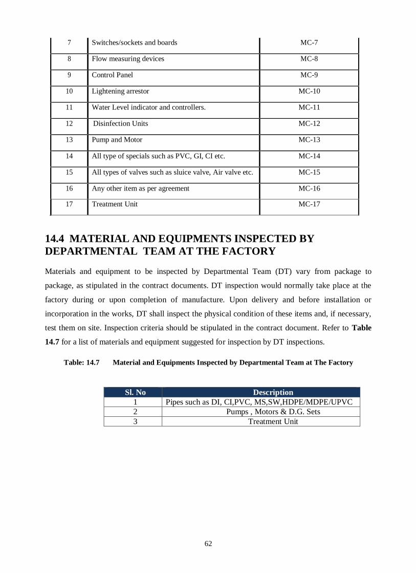
62
7 Switches/sockets and boards MC-7
8 Flow measuring devices MC-8
9 Control Panel MC-9
10 Lightening arrestor MC-10
11 Water Level indicator and controllers. MC-11
12 Disinfection Units MC-12
13 Pump and Motor MC-13
14 All type of specials such as PVC, GI, CI etc. MC-14
15 All types of valves such as sluice valve, Air valve etc. MC-15
16 Any other item as per agreement MC-16
17 Treatment Unit MC-17
14.4 MATERIAL AND EQUIPMENTS INSPECTED BY
DEPARTMENTAL TEAM AT THE FACTORY
Materials and equipment to be inspected by Departmental Team (DT) vary from package to
package, as stipulated in the contract documents. DT inspection would normally take place at the
factory during or upon completion of manufacture. Upon delivery and before installation or
incorporation in the works, DT shall inspect the physical condition of these items and, if necessary,
test them on site. Inspection criteria should be stipulated in the contract document. Refer to Table
14.7 for a list of materials and equipment suggested for inspection by DT inspections.
Table: 14.7 Material and Equipments Inspected by Departmental Team at The Factory
Sl. No Description
1 Pipes such as DI, CI,PVC, MS,SW,HDPE/MDPE/UPVC
2 Pumps , Motors & D.G. Sets
3 Treatment Unit

63
15.0 CONTROL OF CIVIL STRUCTURAL WORKS
AND WATER RETAINING STRUCTURES
This section of the Quality assurance and Quality Control Manual covers the testing of works
and working procedures and sequences for general civil and structural works. The key elements
to be inspected in these works are concreting brickwork and finishes. The requirements for
testing and control of materials for these works are already described in previous section.
15.1 CEMENT CONCRETE & MORTAR
15.1.1 Proportions of Cement Concrete
As per IS 456: 2000 Nominal mix concrete may be used for concrete of M 20 or lower. The
proportions of materials for nominal mix concrete shall be in accordance with provision of BIS
as given in Table 15.1;
Table: 15.1 Proportions of Nominal Mix Concrete
Grade of Concrete Total Quantity of dry
Aggregate by Mass per 50 kg of
cement, to be taken as the sum
of the individual masses of Fine
and Coarse Aggregate, Kg,
Max.
Proportion of Fine
Aggregate to Coarse
Aggregate (By Mass)
Quantity of water per 50
kg of cement, Max. in
litre.
1 2 3 4
M5 800 Generally 1:2 but subject to upper limit of 1: 1.5 and
a lower limit of 1: 2.5
60
M 7.5 625 45
M 10 480 34
M 15 330 32
M 20 250 30
NOTE- The proportions of the fine to coarse aggregate should be adjusted from upper limit to
lower limit progressively as the grading of the aggregates becomes finer and the maximum size of
the coarse aggregate becomes larger. Graded coarse aggregate shall be used.
For an average grading of the fine aggregate (that is, Zone II of Table 4 of IS 383), proportions shall be
1:1.5, 1:2 and 1:2.5 for maximum size of aggregates 10 mm, 20mm and 40mm respectively.

64
The cement content of the mix specified in above Table for any Nominal mix shall be
proportionately increased if the quantity of water in a mix has to be increased to overcome the
difficulties of placement and compaction, so that the water – cement ratio as specified is not
exceeded.
The Civil engineering Hand Book provides strength expected to be attained by concrete of different
proportions and the permissible stresses are laid down as given in Table 15.2
Table: 15.2 Strength of Concrete of Different Proportions
Grade of concrete Characteristic compressive strength In Kg/cm2
At 7 days At 28 days
M10- 1:3:6 70 100
M15- 1:2:4 100 150
M20- 1: 1.5:3 135 200
M25- 1:1:2 170 250
15.1.2 Proportions of Cement Mortar
IS 2250: 1981 provides different grade of mortar for use in masonry work as given in Table 15.3
Table: 15.3 Grades of Masonry Mortar
Grade Compressive strength at 28
days in N/mm2
Cement: Sand
MM - 0.7 0.7-1.5 1:8
MM - 1.5 1.5-2.0 1:7
MM – 3 3-5 1:6
MM – 5 5-7.5 1:5
MM - 7.5 7.5 and above 1:4
M - 7.5 7.5 and above 1:3

65
The selection of mortar will be governed by the strength required by the masonry and reference may
be made in IS: 1905- 1987 for knowing the suitability of combination of various types of mortars
and grade of bricks for the different strength required for the masonry.
The concrete should be kept moist throughout 24 hours a day for the specified number of days for
adequate curing by flooding with water, or by putting moist gunny bags. Adequate separate labour
and supervisor should be deployed for curing work, in ensuring that this important component of the
work is satisfactorily conducted.
Table: 15.4 Type of Test for Concreting
Concreting QC-P-02
Sl. No. Type of Test Test Report Format No.
Frequency of Test Timing of Test/
Inspection
1 Compressive strength as per IS :516-1959
A/TR-05 Clause 10.4 (72-73)
One test for 1-5 m3 of concrete.
Two tests for 6-15 m3 of concrete.
Three tests for 16-30 m3 of concrete.
Four tests for 31-50 m3 of concrete +one set every 50 m3 of additional concrete work.
Test samples to be taken while pouring. Tests to be done as specified in the contract.
2 Slump test per IS :1199-1959
A/TR-6 Clause 10.4 (72)
Random checks throughout concreting period as directed by the Engineer
Before pouring concrete
3 Steel reinforcement placement and bending
Daily Report Before pouring concrete Before pouring concrete
4 Concrete Pour Report C/QRF-4 When pouring is done Immediately after pouring
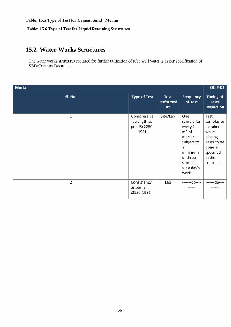
66
Table: 15.5 Type of Test for Cement Sand Mortar
Table: 15.6 Type of Test for Liquid Retaining Structures
15.2 Water Works Structures
The water works structures required for further utilization of tube well water is as per specification of SBD/Contract Document
Mortar QC-P-03
Sl. No. Type of Test Test Performed
at
Frequency of Test
Timing of Test/
Inspection
1 Compressive strength as
per IS: 2250-1981
Site/Lab One sample for every 2 m3 of mortar subject to a minimum of three samples for a day's work
Test samples to be taken while placing. Tests to be done as specified in the contract.
2 Consistency as per IS :2250-1981
Lab -------do----------
-------do----------

67
15.3 CONVENTIONAL UNITS OF CANAL AND SURFACE
SOURCE AS PER REQUIREMENT OF THE PROJECT BASED
WATER SUPPLY SCHEMES
The various units of canal based water supply scheme with their purpose is tabulated in Table 15.7 below;
Table: 15 .7 Units Of Water Supply Scheme
Sl. No. Description Purpose
1 In Take works For with drawl of water from surface source and to ensure entrance velocity of 0.60-0.90cm/sec.
2 Inlet channel For conveyance of raw water to sedimentation and storage tank and it should be laid at correct gradient/alignment.
3 Storage cum Sedimentation tank
It should be made water tight to reduce losses.
4 Underground suction cum scour well
Collection chamber for pumping water should be tested for water tightness.
5 Pump Chamber To house machinery and other equipment and shall be constructed as per standard departmental design.
6 Pumping plants Centrifugal pumps as per IS:9542-1980 are installed for
pumping raw water to high level Tank and clear water to O H S R.
7 High level Tank For distribution of raw water to filter units and should
have scour and over flow arrangement. The structure should be tested for water tightness.
8 Slow sand filter/ rapid sand filter
Provided for filtration of water. The structure is provided
with under drainage, filter media, inlet outlet channels as
per specifications. The structure should be tested for water tightness.
9 Clear water reservoir For storage of clear water, and is provided with
scour/over flow pipes. Structure should be tested for water tightness.
10 OHSR Elevated R.C.C. Storage Tank to supply water to
consumer at minimum residual pressure of 12m head. The
staging of tank will be as Guided by IS: 11682-1985 foundation design shall depend on bearing capacity of soil.
11 Disinfection Disinfection of water shall be carried out by Mechanical chlorinator using chlorine Solution or silver ionization based plant.
15.4 TESTING OF MATERIALS

68
All the materials proposed to be used in the works must have been tested by the contractor and
approved by the Department well before the start of work at site. The contractor shall submit the
concrete pouring report to the Department as and when concreting is done and shall obtain the
approval of the Department when a particular stage is completed and before proceeding to the
next stage.

69
16.0 CONTROL OF PIPELINE WORKS
This section of the QA/QC Manual covers the testing and inspection of workmanship for pipeline
works (i.e. Water). An inspection checklist for pipeline works is included in Appendix A.
16.1 GENERAL
The pipe-laying appears simple, but it requires too much care while laying, along with close watch
to ensure the levels required for quality assurance to attain a satisfactory job. In pipe laying process,
generally the whole of the work takes place below the ground surface and the jointing and bedding
of pipes must be carried out with precision. Pipes should be laid according to specified grade in
straight lengths with least number horizontal and vertical bends.
It should be taken care of that pipes are not to be bedded directly on large stones. Too much
precision is necessary for ensuring quality of work; joints and jointing materials should be kept
perfectly clean. If the quality of work is not ensured it will prove more costing in terms of future
repairs, since the cost of locating and repairing of leaks is very high. All specials and fittings etc
should be installed at the same time of main pipe installation work, without leaving gaps for later
insertion.
16.2 EXCAVATION AND BACKFILLING
Joint holes should be excavated before the pipe is lowered in to position, and must give enough
room for the man to reach round to the underside face of the joint. For large-diameter the joint hole
must be large enough for the worker to crouch down beside the pipe and reach the lower face of the
joint
Backfilling must be completed in layers and laid according to specified requirements. Mechanical
compaction should be conducted to achieve the required level of compacted density as per the
contract document and specification. All large stones liable to damage the coating of the pipe must
be removed from contact with the pipe.
Additional excavation is to be completed at localized positions, in accommodating the joints and so
ensuring that the full length of the pipe barrel rests directly on the trench bedding.
To ensure firm bedding conditions, the final excavation and dressing of the last 15 cm to trench bed
formation level, should be completed manually and not by mechanical excavator

70
16.2.1 Laying and jointing of UPVC Pipes and Specials
While there is no hard-and-fast rule about which direction pipes should be laid if coupler joints are
to be provided. The PVC pipes having one end socketed the care should be taken that direction of
socket end should preferably be against the flow of water, the laying of PVC pipeline should be
straight and in correct alignment and laid on levelled bed. While jointing PVC Pipes and specials it
should be ensured that the surface of end of PVC pipe and inner side of socket where solvent
solution is to be applied remain clean and dust free. After applying solvent solution on the surface
of UPVC pipes it should not be jointed immediately but should be kept open for a while then it
should be inserted into socket or coupler by keeping wooden log on the other end of pipe and
hammering it until the pipe is inserted into full depth of socket/coupler. At the end of each day’s
work the last pipe laid shall have its open ends securely closed with a gunny bag or a wooden plug
or PVC cap to prevent entry of rain water, soil, rats and any other foreign matter into the pipe. The
cutting of the PVC pipe shall be cleanly cut and reasonably square to the axis of the pipe or may be
chamfered.
Jointing must be carried out in minimum possible time, time of making complete joint being not
more than one minute. Joints should not be disturbed for at least 5 minutes. Half strength is attained
in 30 minutes and full in 24 hours. Gluing should be avoided in rainy or foggy weather.
16.2.2 Laying & jointing of HDPE pipes and specials
A pipeline is only as strong as its weakest connection. When it comes to joining HDPE pipe, there
are several common methods that are used, each with its advantages and disadvantages. There are
different methods: butt welding, electro fusion &, flanging – focusing predominantly on the ease and
speed of installation, the need for specialised equipment and experienced personnel, and the strength
and reliability of the joint.
Butt Welding
Butt welding (or butt fusion) jointing is a thermo fusion process which involves the simultaneous
heating of the ends of two components which are to be joined until a melt state is attained on each
contact surface, thereby producing a permanent, economical and flow-efficient connection.
The two surfaces are then brought together under controlled pressure for a specific cooling time and
homogeneous fusion is formed upon cooling. The resultant joint is resistant to end thrust and has
comparable performance under pressure to the pipe.
This method of jointing requires an electrically heated plate to raise the temperature of the pipe ends
to the required fusion temperature and is used for PE63, PE80 and PE100 grades of material for pipe
of size 32mm and above of the same Standard Dimension Ratio (SDR). When joining pipes using
butt welding techniques.

71
The important steps involved in making a butt welded joint are:
Pre-welding procedure
1. Create an environment conducive to repeatability and reproducibility, thus a clean tidy
and stable environment at the point of fusion
2. Ensure the use of clean and appropriate equipment
3. Only use trained personnel
4. Draw up preliminary welding procedures
5. Weld according to preliminary welding procedures
6. Perform a visual inspection on the welded section
7. Perform mechanical tests on welded sections
8. Make process changes until all aspects achieve a pass status
9. Continue with the welding processes and make sure to record all important parameters
10. Make use of check sheets to ensure accurate tracking of all important steps and
parameters
Welding Process
1. Place the pipes in clamps with ends against the trimming tool and pipe markings
aligned
2. Align and level components using support rollers
3. Tighten the pipe clamps to grip and re-round the pipes
4. Use the trimming tool to ensure continuous shavings are cut from each surface
5. Check that there is no visible gap between the trimmed faces
6. Place the heater plate in the machine and close the clamps so that the surfaces to be
joined are touching the plate
7. Using the hydraulic system, apply the pressure previously determined
8. Maintain the applied pressure until the pipe begins to melt and uniform bead of 2-
3mm is formed on each end
9. Check that the pipe does no slip in the clamps. The pipe ends must maintain contact
with the heater plates
10. Once the heat soak time is completed, remove the heater plate, ensuring that the plate
does not touch the melted surfaces
11. Immediately close the clamps and bring the melted surfaces together at the previously
determined pressure
12. Hold under pressure for the appropriate cooling time
Electro fusion
Another technique using heat fusion joining technology is electro fusion. Electro fusion welding
systems are considered the most highly developed cost-effective and safe method for joining
polyethylene pipes today.
This jointing process uses heat generated from electricity to melt both the pipe wall and the pipe
surface, creating a completely homogenous joint that is stronger than the pipe itself. Thanks to its
versatility, electro fusion can be used to weld together pipes or fittings from different PE materials
and different thicknesses as long as there is compatibility of melt flow index and raw material
density.

72
Another key advantage of electro fusion is that it is particularly suited to installations where access
is difficult, such as in trenches or around other pipes.
A typical electro fusion weld is carried out by a trained welder and includes the following steps:
Pre-welding procedure
1. Create an environment conducive to repeatability and reproducibility, thus a clean tidy
and stable environment at the point of fusion
2. Ensure the use of clean and appropriate equipment
3. Only use trained personnel
4. Draw up preliminary welding procedures
5. Weld according to preliminary welding procedures
6. Perform a visual inspection on the welded section
7. Perform mechanical tests on welded sections
8. Make process changes until all aspects achieve a pass status
9. Continue with the welding processes and make sure to record all important parameters
10. Make use of check sheets to ensure accurate tracking of all important steps and
parameters
Welding Process
1. Check that pipe is cut at 90° to the pipe axis
2. Mark the fusion zone on the pipe and scrape to remove oxide layer
3. Clean the scraped area of the pipe, and fittings (avoid touching the fusion zone)
4. Mark the insertion depth (half the length of the fitting) on both pipe ends to be joined,
clamping the components in place if required
5. Insert the pipe ends into the Electro fusion fitting. For larger diameters, assembly can
be assisted by tapping around the face with a plastic hammer
6. Start the fusion process, using a preheating phase if applicable
7. Wait the appropriate cooling time and quality check the fusion
8. Mark the fusion parameters on the pipe
Flanged Connections
Flanged joints are normally used to connect PE pressure pipelines to valves, pumping stations and
pipelines of other pipe materials. The joint must be able to transfer long-term axial forces with
maintained tightness, which requires use of suitable components and a correct assembly .
The components in a flanged joint for HDPE pipes are:
Stub-ends or flanged adaptors
Back-up flanges
Gaskets (pressure and chemical appropriate)
Bolts
Washers
The general procedure for making flanged connections is:
1. Flanges and gasket should be centred, supporting one or both halves of the joint if
necessary
73
2. The end surfaces of the stub-ends must be close to each other before the bolts are
tightened to avoid elongation of the pipe during joint assembly
3. Bolts are tightened crosswise in at least six stages, starting with finger tightening, and
consequently using a torque wrench
4. Additional tightening to the recommended torque should be carried out several hours
later and also on the next day
As a rule of thumb, the sealing pressure should be at least twice the maximum internal pressure in
the pipe.
16.2.3 Trench Preparation
The trench must be prepared and be in good condition before the pipe is lowered into it. This means
its bottom must be in level and made free of all sharp stones, the trench must be dry, and its sides
must be made safe against slips or collapse. Preparation of pipe trenches is a very important activity.
All the precautions regarding safety must be followed while the trench preparation, the excavated
earth should be placed away from the both sides of trenches Wooden planks should be placed across
the trenches in front of entry gate of houses.
If the Junior Engineer thinks the Contractor not taking enough precautions to support the trench he
should point out the dangers and offer advice to remedy the matter. Usually, the Junior Engineer
should find no difficulty in convincing the contractor’s representative, but if unreasonable risks
persist, the Junior Engineer should discuss the problem with his superiors.
All heavy pipes must be handled with care to prevent damage to them and their sheathing. Slings or
ropes should be used to lift heavy pipes. Chains and wire ropes should be forbidden. Even ropes
must be used with care to prevent damage to the sheathing. It is a good precaution for the Junior
Engineer to insist that proper slings in sufficient numbers are brought on the job at the very start.
16.2.4 Cover to Pipes
All pipes are normally laid below ground and the standard amount of cover is 900 mm above the top
of the pipe. However, cover of less than 1000 mm is not to be permitted below a public road, or
traffic loading would cause damage to pipes. Use of CI/DI/MS pipe is a option for road crossings to
mitigate the heavy vehicular traffic.
16.2.5 Pipeline log book
It is essential to maintain a pipe log book in which are entered full details of the laying of the
pipeline covering each and every pipe, giving frequent levels, details of fittings and connections,
74
And a running total of the chainage lay, together with sketch plans showing other services
encountered and dimensions to locate the position of the pipe from time to time.
16.2.6 Thrust block considerations
At every change of direction in the pipeline, at every change of size, at connection and valves, thrust
blocks are necessary. Complete or partial failure of a pipe at a bend is almost always due to soil
movement behind the block.
Thrust blocks for vertical bends are essential, and those on bends down may have to be reinforced.
Other thrust blocks, such as those adjacent to river banks, ditches, or depressions in the ground,
must be carefully placed, as there is a possibility of collapse of earth at these points.
16.2.7 Flanged Pipes
Two practical points need to be noted when setting up flanged piping;
Care must be taken not to tighten up the flange bolts until it is certain that the exact alignment
required has been achieved. If there is lack of alignment between flanges the tightening of the bolts
can break the flange.
The stipulations of the appropriate IS code must be strictly adhered which are generally followed by
the manufacturers/suppliers.

75
17.0 CONTROL OF MECHANICAL & ELECTRICAL
WORKS
This section of the QA/QC Manual gives an overview of the quality control requirements for
electromechanical works, such as water treatment and supply systems, pumping systems, dry run
sensor for submersible pumps, auto run sensor for solar pumps, power supply and distribution
systems. The requirements for testing and control of input materials and components, including
manufacturers’ certification, and departmental party inspections.
Materials and components to be incorporated into electromechanical works shall be inspected by
Department as soon as they are delivered, to ensure that they meet the specifications and design
requirements, are in agreement with shipping documentation, and are accompanied by
manufacturer’s certification, third party or departmental inspection certificates, as applicable.
Accepted materials and equipment shall be properly stored by the contractor until needed. If
manufacturer’s installation instructions conflict with design or contract requirements, the
Department shall be notified immediately. Installation shall proceed only after the materials and
components are approved by Department
A series of inspections and tests during installation and completion of electromechanically works
shall be performed by the contractor or the equipment manufacturer and witnessed by Department
as follows:
17.1 PREPARATORY INSPECTIONS: Prior to installation, the civil and
structural works where electromechanical equipment is to be installed shall be inspected to ensure
conformance with designs and equipment installation requirements.
17.2 INSTALLATION INSPECTIONS AND TESTS: A system of
inspections and tests, as specified in the contract or recommended by the equipment manufacturer,
shall be employed throughout movement to position and installation of equipment and systems.
Inspections shall be performed by Department at critical points during installation. The critical
points are indicated below in Table 17.1;
Table: 17.1-Critical Points for Inspection
Sl.
No
Critical Points Items
1. Installation of Mechanical
Equipments
Lowering of Submersible Pump to proper depth
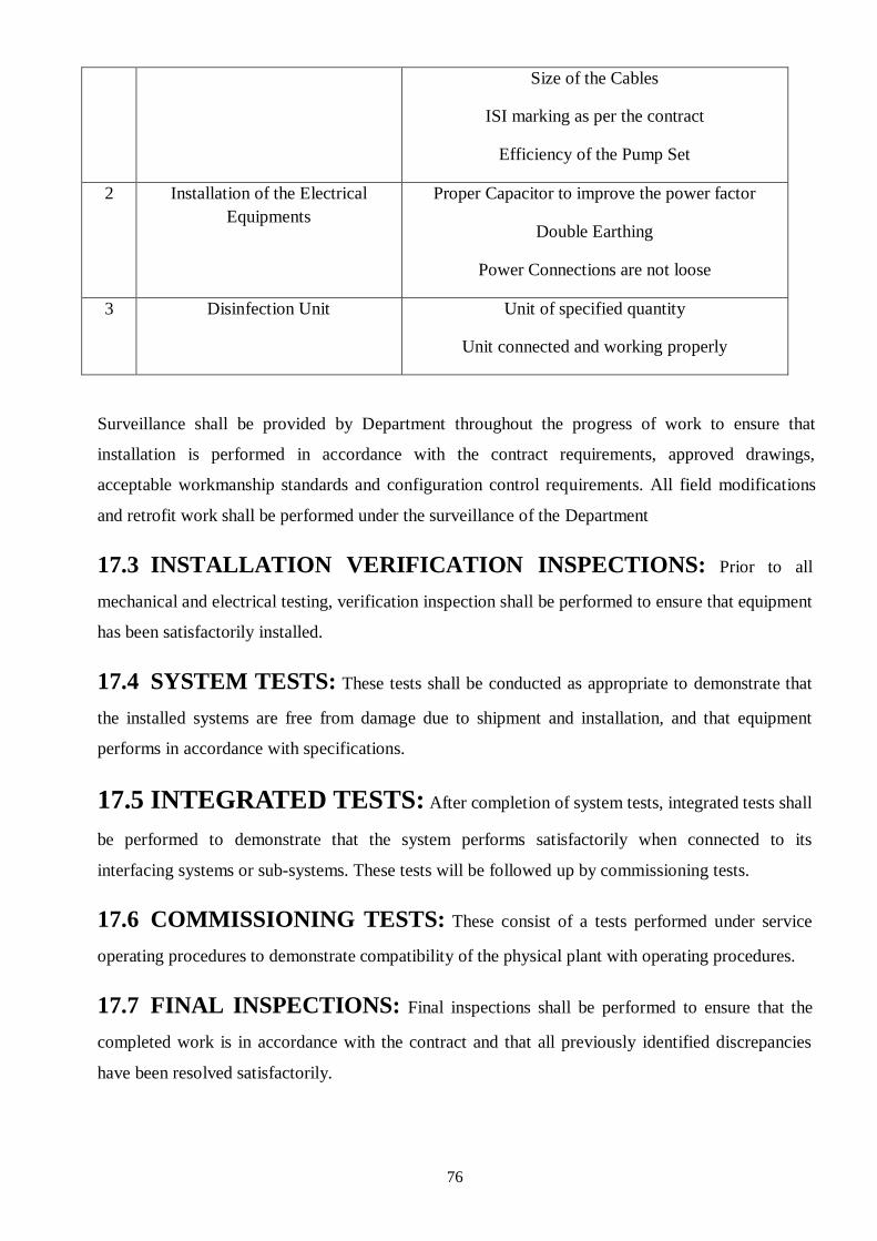
76
Size of the Cables
ISI marking as per the contract
Efficiency of the Pump Set
2 Installation of the Electrical
Equipments
Proper Capacitor to improve the power factor
Double Earthing
Power Connections are not loose
3 Disinfection Unit Unit of specified quantity
Unit connected and working properly
Surveillance shall be provided by Department throughout the progress of work to ensure that
installation is performed in accordance with the contract requirements, approved drawings,
acceptable workmanship standards and configuration control requirements. All field modifications
and retrofit work shall be performed under the surveillance of the Department
17.3 INSTALLATION VERIFICATION INSPECTIONS: Prior to all
mechanical and electrical testing, verification inspection shall be performed to ensure that equipment
has been satisfactorily installed.
17.4 SYSTEM TESTS: These tests shall be conducted as appropriate to demonstrate that
the installed systems are free from damage due to shipment and installation, and that equipment
performs in accordance with specifications.
17.5 INTEGRATED TESTS: After completion of system tests, integrated tests shall
be performed to demonstrate that the system performs satisfactorily when connected to its
interfacing systems or sub-systems. These tests will be followed up by commissioning tests.
17.6 COMMISSIONING TESTS: These consist of a tests performed under service
operating procedures to demonstrate compatibility of the physical plant with operating procedures.
17.7 FINAL INSPECTIONS: Final inspections shall be performed to ensure that the
completed work is in accordance with the contract and that all previously identified discrepancies
have been resolved satisfactorily.

77
17.8 PARAMETERS TO BE DECLARED BY THE
MANUFACTURER
The pumps supplied by the manufacturer shall be marked with the following parameters and shall be
declared by the manufacturer.
(i) Model, size and serial number of the pump;
(ii) Rated speed, total head and discharge at the guaranteed duty point;
(iii) Range of Head;
(iv) Motor range (kW) Prime mover rating;
(v) Rated voltage
(vi) Rated frequency;
(vii) Number of phases;
(viii) Winding connection;
(ix) Maximum current in amperes;
(x) Class of insulation of motor;
(xi) Manufacture’s name / trade mark;
(xii) Power input in kW;
(xiii) Classification;
(xiv) Number of stages in case of multistage; and
(xv) Self priming time at 1.5 m or 3 m static suction lift.
17.9 PUMP TEST RECORD
The Pump test record shall be maintained.

78
18.0 PROCEDURE OF SAMPLING AND TESTING OF
MATERIALS
Sampling procedures, sample collection, test to be conducted and acceptable test results of widely
used materials in the projects are covered as under;
18.1 CEMENT
18.1.1 SAMPLING PROCEDURES AND SAMPLE COLLECTIONS
The sample collected represents the typical of average properties of material to be tested. Such
sample is said to be the representative sample. Much care and systematic sampling procedure is
required to be followed, which are now standardized by the relevant Standards.
Sampling instrument should be clean and dry when used
Precautions should be taken to protect the sample from contamination.
Sample containers should be of such a size that they are almost completely filled by
the sample.
Sample container shall be sealed airtight after filling and marked with full particular
of the material and the date of sampling.
Quantity of cement offered at one time is called a lot.
This lot is normally divided in to sub lots depending upon its total weight. Quantity of cement
taken by a single operation is called increment. Aggregates of all these increments from the same
sub lot is called gross sample. When these gross samples of each sub lot are reduced by suitable
procedures for laboratory testing, they are called laboratory samples. Equal quantities of cement
from each laboratory sample representing sub lots, are mixed to form composite samples.
The method of sampling from bags is described below;
Divide the entire lot in to sub lots. Sub lots should consist of equal No. of bags.
From each sample at least 2% bags should be sampled.
These bags are to be chosen at random. To ensure randomness following procedure
should be followed. For example, if a lot consists of 600 bags that is 30 tonnes, divide
this lot into 3 sub lots i.e. 200 bags each. Thus N=200. Since at least, 2% bags are to
be sampled, then n=4 bags. Therefore, r=200/4=50. Thus starting from any one point,
every 50th
bag is to be removed.

79
Increments are to be taken by inserting a tube sampler as per IS: 3535. The material so
collected from each bag is 0.75 kg.
Material so collected should be placed in to air tight containers. Cans, plastic bags may
be used. These containers shall be sealed immediately. Gross- samples thus obtained
have to be reduced to laboratory samples by quartering. Reduction should be continued
till about 7-10 kg material required for laboratory sample are obtained.
Equal quantities of material shall be taken from each laboratory sample representing the
sub lot and mixed together to constitute composite sample representing the lot as a
whole. The weight of the composite sample shall be about 7 kg to 10 kg.
All laboratory samples and composite samples should be sealed in an air tight moisture
proof container.
18.1.2 Test for Cement
The cement is the important ingredient of mortar and concrete used for construction purposes.
The various physical and chemical test should be conducted as per prescribed frequency.
Following are the tests to be conducted to judge the quality of cement.
1. Consistency
2. Fineness
3. Soundness
4. Initial and Final Setting Time of Cement
5. Compressive strength
18.1.3 Test for Fineness
To determine the fineness of cement by dry sieving as per IS: 4031 (Part 1) – 1996.The principle
of this is that we determine the proportion of cement whose grain size is larger than specified mesh
size.
The apparatus used are 90µm IS Sieve, Balance capable of weighing 10g to the nearest 10mg, a
nylon or pure bristle brush, preferably with 25 to 40mm, bristle, for cleaning the sieve.
PROCEDURE TO DETERMINE FINENESS OF CEMENT
a) Weigh approximately 10g of cement to the nearest 0.01g and place it on the sieve.
b) Agitate the sieve by swirling, planetary and linear movements, until no more fine material
passes through it.

80
c) Weigh the residue and express its mass as a percentage R1, of the quantity first placed on the
sieve to the nearest 0.1 percent.
d) Gently brush all the fine material off the base of the sieve.
e) Repeat the whole procedure using a fresh 10g sample to obtain R2. Then calculate R as the
mean of R1 and R2 as a percentage, expressed to the nearest 0.1 percent. When the results
differ by more than 1 percent absolute, carry out a third sieving and calculate the mean of the
three values.
Reporting of Results
Report the value of R, to the nearest 0.1 percent, as the residue on the 90µm sieve.
18.1.4 Test for Compressive Strength
METHOD
Gauge a mixture of cement and regarded identified Indian Standard sand in the proportion of 1:3 by weight
using (P/4+3.0) percent of water where P is the percentage of water required to produce a paste of standard
consistency.
Fill the cube moulds (70.6mmx70.6mm) by compacting it for 2 minutes on a vibrating machine at a speed of
12,000±) 400 vibrations per minute. Smoothen the top surface of the cubes with flat side of a trowel.
Immediately upon completion of moulding, place the cube moulds in an atmosphere of 270c±20c and relative
humidity over 90%. After, 24 hours, remove the specimens from the moulds and keep them in water till
testing.
Test the cubes at 3 days and 7 days age in the compression testing machine at such a rate that maximum load
is reached in 80-100 seconds
Report the average compressive strength in N/sqm ( kg/sqm)/Mpa.The reporting is to be made accordingly

81
STANDARD
CEMENT (PPC) IS: 1489 (1)-1991 FLY ASH BASED
Test
Frequency
Ref Codes
Acceptance/Standard
1.Chemical Tests 1. Loss on ignition,
percent by mass
2. Magnesia (Mgo),
percent by mass
3. Sulphuric anhydride (So3)
Percent by mass
4. Insoluble
material, percent
by mass
Once for every source
approval Once for every lot
Once for every 3
months
As per IS: 4032-1985
1. 5.0 % max
2. 6.0 max 3. 3.0 % max
4. x + 4.0(100-
x)/100
where x is the declared
% of flyash in the given
Portland pozzolona
cement
2. Physical Tests (a) Setting Time
(i) Initial
(ii) Final
(b) Soundness (Le-
Chatelier Expansion)
Once for every source
approval
Once for every lot
i) Min.30 min.
ii) Max.600 min.
10mm (max.)
0.8% (max) by
Autoclave method
(c) Compressive
Strength
(i) At 72±1 hr
(ii) At 168±2 hrs
(iii) At 672±4 hr
(d)Fineness
(e) Drying shrinkage
Once for every 3
months
Not less than 16 MPa
strength
Not less than 22 MPa
strength
Not less than 33 MPa
strength
Specific surface shall
not be less than 300
M2/kg
Not be more than
0.15%

82
CEMENT (OPC-43 GRADE) IS : 8112-1989
Test
Frequency
Ref Codes
Acceptance/Standard
1.Chemical Tests
Chlorides (as Cl)
Ratio of Alumina to
that of Iron Oxide
Magnesium (MgO)
Total Sulphur content
(SO3)
Loss on Ignition
Insoluble residue
Lime saturation factor
2. Physical Tests
(a) Setting Time
(i) Initial
(ii) Final
(b)Soundness (Le-
Chatelier Expansion)
(c)Compressive
Strength
(i) At 72±1 hr
(ii) At 168±2 hrs
(iii)At 672±4 hr
(d)Fineness (Blain’s
air permeability
method)
By sieving on 90μ
sieve
Once for every source
approval
Once for every lot
Once for every 3
months
Once for every source
approval
Once for every lot
Once for every 3
months
As per IS: 4032:1985
As per IS : 4031-1988
0.05 % max
0.66 % min
6.0 % max
3.0 % max
5.0 % max
2.0 % max
0.66- 1.02
Not less than 30 min.
Not less than 600 min
10mm (max.)
and 0.8% (max)by
Auto clave method
Not less than 23 MPa
strength
Not less than 33 MPa
strength
Not less than 43 MPa
strength
18.2 AGGREGATE
18.2.1 SAMPLING PROCEDURES AND SAMPLE COLLECTIONS
The method of sampling from stacks on site is described below;
Divide the lot in sub lots.
Minimum weight of gross samples is the minimum No. of increments.
Increments should be drawn with the help of scoop.
Sampling of aggregate from the stacks should be carried out, as for as possible, during
making of the stack.
Number of increments should be equally distributed over the sub-lot.
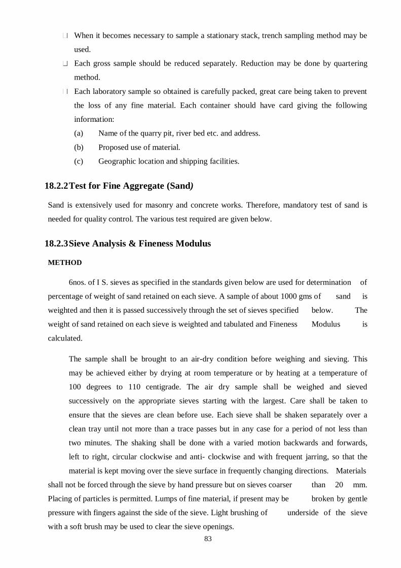
83
When it becomes necessary to sample a stationary stack, trench sampling method may be
used.
Each gross sample should be reduced separately. Reduction may be done by quartering
method.
Each laboratory sample so obtained is carefully packed, great care being taken to prevent
the loss of any fine material. Each container should have card giving the following
information:
(a) Name of the quarry pit, river bed etc. and address.
(b) Proposed use of material.
(c) Geographic location and shipping facilities.
18.2.2 Test for Fine Aggregate (Sand)
Sand is extensively used for masonry and concrete works. Therefore, mandatory test of sand is
needed for quality control. The various test required are given below.
18.2.3 Sieve Analysis & Fineness Modulus
METHOD
6nos. of I S. sieves as specified in the standards given below are used for determination of
percentage of weight of sand retained on each sieve. A sample of about 1000 gms of sand is
weighted and then it is passed successively through the set of sieves specified below. The
weight of sand retained on each sieve is weighted and tabulated and Fineness Modulus is
calculated.
The sample shall be brought to an air-dry condition before weighing and sieving. This
may be achieved either by drying at room temperature or by heating at a temperature of
100 degrees to 110 centigrade. The air dry sample shall be weighed and sieved
successively on the appropriate sieves starting with the largest. Care shall be taken to
ensure that the sieves are clean before use. Each sieve shall be shaken separately over a
clean tray until not more than a trace passes but in any case for a period of not less than
two minutes. The shaking shall be done with a varied motion backwards and forwards,
left to right, circular clockwise and anti- clockwise and with frequent jarring, so that the
material is kept moving over the sieve surface in frequently changing directions. Materials
shall not be forced through the sieve by hand pressure but on sieves coarser than 20 mm.
Placing of particles is permitted. Lumps of fine material, if present may be broken by gentle
pressure with fingers against the side of the sieve. Light brushing of underside of the sieve
with a soft brush may be used to clear the sieve openings.

84
Light brushing with a fine camel hair may be used on the 150 micron IS sieve to prevent
segregation of powder and blinding of apertures. Still or worn out brushes shall not be
used for this purpose and pressure shall not be applied to the surface of the sieve to force
particles through the mesh. On completion of sieving the material retained on each sieve
together with any material cleaned from the mesh shall be weighed. The cumulative
percentage by weight of the total sample passing each of the sieves, to the whole number is
to be reported on Format.
STANDARDS
Test
Frequency
Ref Codes
Acceptance/Standard
1. Particle
Sizes
(a) Sieve
Analysis
Once for every
source approval
Once in a month
IS: 383-
1970
IS: 2386
(Part I) –
1963
IS : 1542-
1992
IS : 2116-
1980
Fine aggregates should be grading for as given
below
IS
Sieve
Design-
ation
Percent by weight passing for
Zone-1
(High
Strength
Conc.)
Zone-
II
(Stand.
Conc.)
Plaster
IS:1542
Masonry
IS:2116
10mm 100 100 100
4.75
mm
90-100 90-100 95-100 100
2.36mm 60-95 75-100 95-100 90-100
1.18mm 30-70 55-90 90-100 70-100
600μ 15-34 35-59 80-100 40-100
300μ 5-20 5-20 20-65 5-70
150μ 0-10 0-10 0-15 0-15
For crushed stone sands, crushed gravel sand the permissible limit on 150 micron I S sieve is increased to 20 %. Tolerance of ± 5 % is allowed except on 600 μ for sand used in concrete. CONTROL MANUAL

85
Coarse aggregate is most important constituent in concrete, which mainly imparts strength to concrete structure. The various test required are given below to judge the hardness of coarse aggregate.
Impact Test Crushing Test
Abrasion Test 10% fine Valu
18.2.4 Sieve Analysis & Fineness Modulus Test (Stone)
METHOD
The stone ballast for use in all types of cement concretes work shall meet the grading requirements
specified below. I.S. sieve of sizes as given below are used and weight retained on each sieve is
found out with the help of balance. The reporting is to be made on format
STANDARDS
Test
Frequency
Ref Codes
Acceptance/Standard
1. Particle Size
(a) Sieve Analysis
Once for every
source approval
Once in a week
IS: 383-1970
IS: 2386
(Part I) –
1963
Grading IS Sieve
Designatio
n
Percentag
e passing
(by
weight)
20 mm
Nomina
l size
40 mm 100
20mm 85-100
10mm 0-20
4.75mm 0-5
12.5
mm
Nomina
l size
16mm 100
12.5mm 85-100
10mm 0-45
4.75mm 0-10
100mm
nominal
12.5mm 100

86
10mm 85-100
4.75mm 0-20
2.36 0-5
CONSTRUCTION QUALITY MANAGEMENT AND SURVEILLANCE SYSTEM QUALITY ASSURANCE
QUALITY CONTROL MANUAL
(b)Flakiness Index and IS: 2386(I) 35% Maximum value of combined
Elongation Index – 1963 Elongation and Flakiness Index
2. Deleterious
Materials (crushed Once for every IS: 383- Deleterious Percentage by
aggregate) source 1970 Material weight
approval IS:2386(II) (Maximum)
At every – 1963
change of (i) Coal and Lignite 1
source (ii) Clay and Lumps 1
(iii) Material finer 3
that 75 micron IS
Sieve
(iv) Soft Fragment --
(v) Shale --
Total % of all. 5
3. Specific Gravity Once for every IS: 383- Test is required for maintaining uniformity
and source 1970 of material brought from the source

87
Density
Approval IS: 2386
Once in a (Part III) –
Fortnight 1963
4. Mechanical properties
(a) Aggregate Once for every IS: 383- 45% maximum by Weight
Crushing Value source 1970
(b) Impact Value approval IS: 2386 45% maximum by Weight
(Part IV) –
1963
(c) 10 percent Fines Once for every Not less than 5 tonnes
source
(d) Abrasion Value approval 50% maximum by Weight
5. Soundness Once for every IS: 383- Maximum Average Loss of weight after 5
source 1970 Cycles
approval IS: 2386 (i) Tested with Sodium Sulphate - 12%
(Part V) – (ii) Tested with Magnesium Sulphate - 18%
1963
6. Surface Moisture Once for every
Content source IS: 383- Test required adjusting the water content in
approval 1970 the mix design before starting any concrete
At every IS: 2386 mixing.
change of mix (Part III) –
design 1963
7. Alkali Reactivity Once for every IS: 383- Innocuous Aggregate
source 1970
approval IS: 2386
(Part VII) –
1963
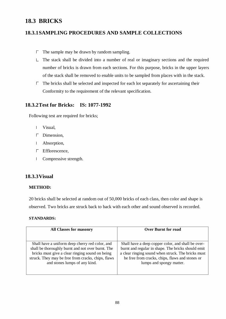
88
18.3 BRICKS
18.3.1 SAMPLING PROCEDURES AND SAMPLE COLLECTIONS
The sample may be drawn by random sampling.
The stack shall be divided into a number of real or imaginary sections and the required
number of bricks is drawn from each sections. For this purpose, bricks in the upper layers
of the stack shall be removed to enable units to be sampled from places with in the stack.
The bricks shall be selected and inspected for each lot separately for ascertaining their
Conformity to the requirement of the relevant specification.
18.3.2 Test for Bricks: IS: 1077-1992
Following test are required for bricks;
Visual,
Dimension,
Absorption,
Efflorescence,
Compressive strength.
18.3.3 Visual
METHOD:
20 bricks shall be selected at random out of 50,000 bricks of each class, then color and shape is
observed. Two bricks are struck back to back with each other and sound observed is recorded.
STANDARDS:
All Classes for masonry
Over Burnt for road
Shall have a uniform deep cherry red color, and
shall be thoroughly burnt and not over burnt. The
bricks must give a clear ringing sound on being
struck. They may be free from cracks, chips, flaws and stones lumps of any kind.
Shall have a deep copper color, and shall be over-
burnt and regular in shape. The bricks should emit
a clear ringing sound when struck. The bricks must
be free from cracks, chips, flaws and stones or lumps and spongy matter.

89
18.3.4 Dimensions
METHOD:
20 whole bricks shall be selected at random and their dimensions shall be measured by spreading the bricks in contact with one another, length, breadth and height wise on a level surface. These dimensions should be within the tolerance limits specified below:
All Classes Non Modular Bricks (In mm)
Length
4600 ± 80
Standard size of one brick
Length: 230 mm
Width: 110 mm
Height : 70 mm or 30 mm
Width
2200 ± 40
Height
1400 ± 40 for 70 mm
high
600 ± 40 for 30 mm high
Straight Over Burnt Bricks
Length
177.5’’ to 182.5’’
Standard size of one brick
Length : 8 7/8’’
Width : 4 1/4’’
Height : 2 5/8’’
Width
85’’ to 87.5’’
Height
52.5 to 55.0’’
Modular Bricks
Length
3800 ± 80 mm
Standard size of one brick
Length : 190 mm
Width : 90 mm
Height : 90 mm or 40 mm
Width 1800 ± 40 mm
Height
1800 ± 40 cm for 90 mm
high
± 40 for 40 mm high
ONSTRUCTION QUALITY MANAGEMENT AND

90
18.3.5 Water Absorption
METHOD:
5 whole dry bricks shall be selected at random from the sample obtained. The test specimen shall
be weighted and shall then be completely immersed in clean water at room temperature and
allowed to remain in this state for a period of 24 hours. The specimen shall then be taken out,
wiped with damp cloth and then weighed immediately.
Absorption percentage by weight =
A: Weight of dry specimen
B: Weight of the specimen after 24 hours immersion in cold water.
STANDARD
Sl. No.
Class
Ref. codes
Limit
1
For Masonry
IS: 3495(II)-1992
Not more than 20% by
weight
2
Straight over burnt for road work
Not more than 10% by weight
18.3.6 Efflorescence
METHOD:
Five dry bricks shall be selected at random from the sample of bricks obtained. Each brick shall be
placed on end in a flat bottom dish containing distil water. The depth of emersion of the brick being
not less than 2.5 cm. The whole arrangement shall be allowed to stand in a warm (i.e. 18 to 30oC)
and well ventilated room until all the water in the dish evaporate. When the water is absorbed and
the bricks appear to be dry, a similar quantity of distilled water shall again be placed in the dishes
and the same allowed to evaporate as before. At the end of this period the bricks shall be examined
for efflorescence.

91
STANDARDS:
Sl. No
Standard
Definition
Ref. code
1 Nil
When there is no perceptible deposit of
efflorescence
IS: 3495(II)-
1992
2 Slight
When not more than 10% of area of the brick is
covered with a thin deposit of salt.
3 Moderate
When there is a heavier deposit than under slight
and covering up to 50% of the brick surface but
unaccompanied by powdering of flaking of the
surface.
4 Heavy
When there is a heavy deposit of salts covering up
to 50% or more of the brick surface but
unaccompanied by powdering of flaking of the
surface.
5 Serious
When there is a heavy deposit of salts accompanied
by powdering and for flaking of the surface and
tending to increase with repeated weathering of the
specimens.
18.3.7 Compressive Strength
METHOD:
The bricks when used in masonry are subjected to compressive stresses due to load transferred. So in
order to enable them to sustain the load coming on them, they should be tested for their compressive
strength.
The bricks shall be immersed in water at 25 to 29 0C for 24 hours. They shall then be removed and
allowed to dry at room temperature for about 5 minutes and wiped free from surplus moisture. Their
frogs shall be filled with mortar composed of one part Portland cement and three parts clean sand
graded to 3 mm and down. The bricks shall then be stored under damp sacks for 24 hours. After the
expiry of this period, they shall be immersed in water for 3 days.
The compression plate of the testing machine shall have a ball seating in the form of a portion of a
sphere, the centre of which coincides with the centre of the face of the plate. The load shall be
applied axially at a uniform rate of approximately 140 kg/cm2 per minute until failure occurs. The
compressive strength of bricks shall be expressed in kg/cm2or N / mm
2. During testing of bricks if
any brick is found to have strength more than 20% of the group, it shall be limited to +20%only for
calculating the average strength.

92
Class Designation
Average compressive strength not less than
Ref. IS codes
N / mm2
Kg / cm2
35 35 350 IS : 3495 (I) – 1992
30 30 30
25 25 250
20 20 200
17.5 17.5 175
15 15 150
12.5 12.5 125
10 10 100
7.5 7.5 75
5 5 50
3.5 3.5 35
The first class bricks as per technical specifications should have strength of 10.5 N / mm2
18.4 CONCRETE
18.4.1 SAMPLING PROCEDURES AND SAMPLE COLLECTIONS
From mixer: At least three approximately equal sample increments totalling 0.02m3 (20
liters) shall be taken from a batch during its discharge. Each sample increments are to be
collected by passing clean dry receptacle across a stream of concrete. Receptacle should be
such as to avoid segregation. Buckets of 7to 10 liters capacity of G. I. will serve the
purpose.
From batch: Sample shall be taken while a batch of concrete is being prepared or
immediately after it has been discharged on site. Sample shall be collected at not less than
five well distributed position, avoiding edge of the mass where segregation may have
occurred.

93
The composite sample obtained by either of the methods mentioned above shall be mixed
on a non-absorbent base either with a shovel or trowel to ensure uniformity. These samples
can then be used for conducting:
a) slump test,
b) Preparation of cube for strength test.
18.4.2 Test of Cement Concrete
18.4.2.1 Slump Test:
METHOD
This test is carried out in the field during the course of concreting. The slump test apparatus as per
IS: 7320- 1974is used for determination of slump of fresh concrete. The cone (30x20x10cm) is
placed on a flat non absorbent surface and then filled with concrete mix in four different layers of
equal thickness. Each layer is template 25 times by the 16 mm dia bullet pointed 60 cm length iron
pinning rod. The stroke is applied uniformly over the entire area with a force that the rod just
penetrates the full depth of the layer compacted. After the filling is completed the conical vessel or
mould is removed by rising vertically and the moulded concrete is allowed to subside. The
subsidence height of the specimen is measured in mm and recorded in terms of slump.
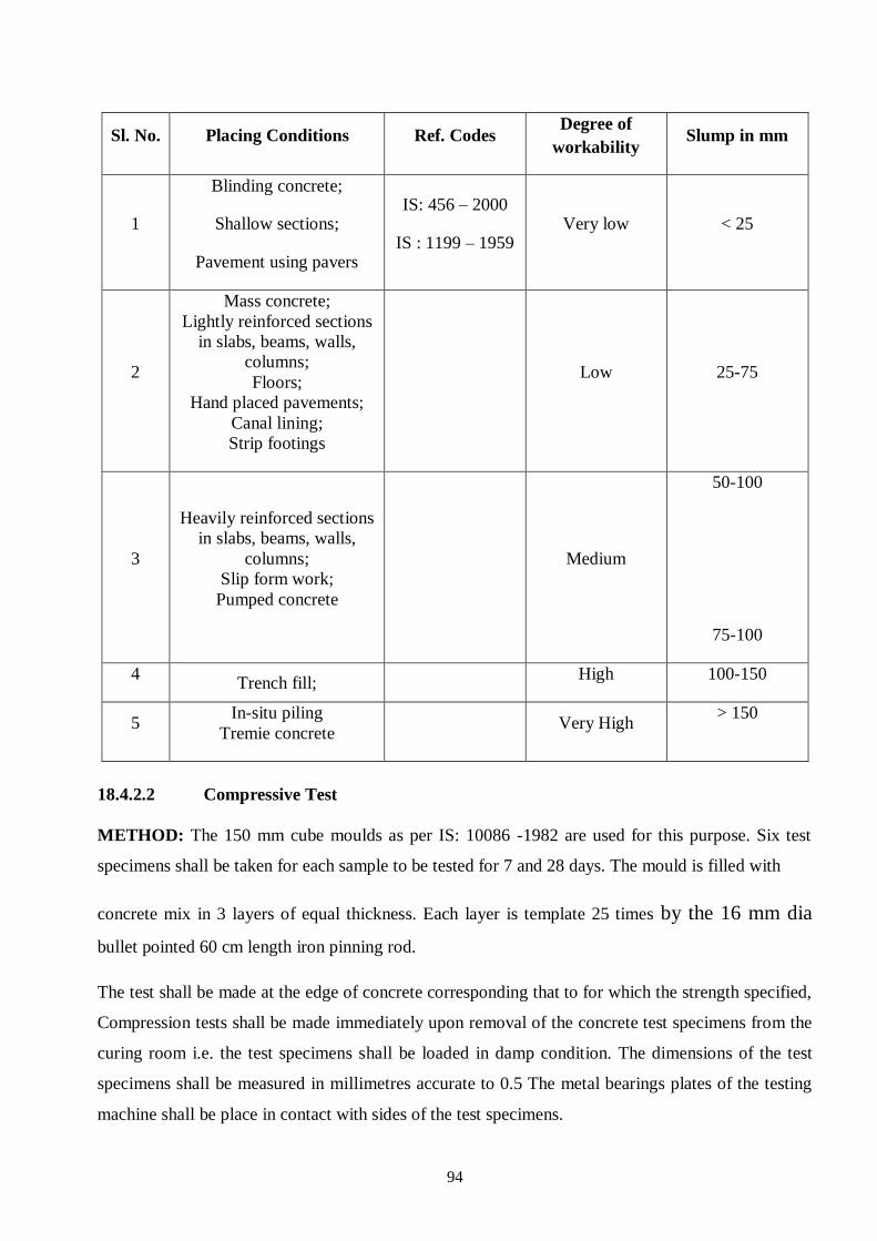
94
Sl. No. Placing Conditions Ref. Codes Degree of
workability Slump in mm
1
Blinding concrete;
Shallow sections;
Pavement using pavers
IS: 456 – 2000
IS : 1199 – 1959 Very low < 25
2
Mass concrete;
Lightly reinforced sections
in slabs, beams, walls,
columns;
Floors;
Hand placed pavements;
Canal lining;
Strip footings
Low 25-75
3
Heavily reinforced sections
in slabs, beams, walls,
columns;
Slip form work;
Pumped concrete
Medium
50-100
75-100
4 Trench fill;
High 100-150
5 In-situ piling
Tremie concrete Very High
> 150
18.4.2.2 Compressive Test
METHOD: The 150 mm cube moulds as per IS: 10086 -1982 are used for this purpose. Six test
specimens shall be taken for each sample to be tested for 7 and 28 days. The mould is filled with
concrete mix in 3 layers of equal thickness. Each layer is template 25 times by the 16 mm dia
bullet pointed 60 cm length iron pinning rod.
The test shall be made at the edge of concrete corresponding that to for which the strength specified,
Compression tests shall be made immediately upon removal of the concrete test specimens from the
curing room i.e. the test specimens shall be loaded in damp condition. The dimensions of the test
specimens shall be measured in millimetres accurate to 0.5 The metal bearings plates of the testing
machine shall be place in contact with sides of the test specimens.

95
Cushioning material shall not be used in the machine. In the case of cube, the test specimen shall be
placed in the machine in such a manner that the load is applied to the sides of the specimen. An
adjustable bearing block shall be the used to transmit the load to the test specimen. The size or lower
section of the bearing block shall be kept in machine as the head of the testing machine is brought to
a bearing on test specimen.
The load shall be applied axially without shock at the rate of approximately 140 kg/ cm2 per minute.
The total load indicated by the testing machine at failure of the test specimen shall be recorded and
the unit compressive strength calculated from the measured dimensions of the test specimen. The
type of failure and appearance of the concrete shall be noted.
STANDARDS OF CHARACTERISTIC STRENGTH
Group
Grade Designation
Compressive strength on 15 cm cubes
for work test
In N/mm2
Min at
7 days Min at 28 days
Ordinary Concrete
M 10
M 15
M 20
7.0
10.0
13.5
10
15
20
Standard Concrete
M 25
M 30
M 35
M 40
M 50
M 55
17.0
20.0
23.5
27.0
25
30
35
40
50
55
High strength
Concrete
M 60
M 65
M 70
M 75
M 80
60
65
70
75
80

96
18.5 STEEL
18.5.1 SAMPLING PROCEDURES AND SAMPLE COLLECTIONS
Take sufficient rods, at random, from each lot to obtain desired number of samples. If more
than one rod is needed, they must be taken from different bundles.
Using a hacksaw, cut off as many one-metre long pieces as are needed for the test from the
sampled rod or rods.
Tie the cut-off pieces from each lot together with wire and mark properly.
Every bundle of steel samples must be identified with a proper label and be sent to the
laboratory under cover of a sample data from giving:
Type of steel
Nominal size
Cross-section
Grade and mould number
Test to be done on the samples.
18.5.2 Test of Steel for Reinforcement IS: 1786-2008
METHOD:
The steel should be got tested in authorized laboratories before it is used for work at site. Following
tests should be conducted for reinforcement steel,
Mass per meter/ dia
Yield stress (0.2% Proof stress)
Ultimate tensile strength
Elongation
Cold bend rebend test
STANDARDS
The steel shall be clean and free from loose mill scale, loose rust, mud, oil, grease or any other
Coating which may reduce or destroy the bond between the concrete and steel. A slight film of
rust may not be regarded as harmful but steel shall not be visibly pitted by rust.

97
Test Frequency Ref Codes Acceptance/Standard
1. Chemical Tests
Carbon
Sulphur
Phosphorus
(Sulphur+
Phosphorus)
2. Physical Test
Ultimate tensile
strength
0.2% proof stress
% Elongation
Bend Test
Re-bend Test
Mass per meter run
(kg)
Once for every source
approval
Once for every lot
Once every 3 months
Once for every source
approval
Once for every lot
Once every 3 months
IS: 228 (1-24)-
1987
IS: 1786: -1985
IS: 1608-2005
IS :1599-1985
IS :1786-2008
0.30 Max.
0.06 Max.
0.06 Max.
0.11 Max.
10% more than the actual
0.2% proof stress but not
less 485 MPa
Min. - 415 MPa
Min.- 14.5 %
To be satisfactory
To be satisfactory
6.31 ±3% for 32 mm Dia,
4.830 ±3% for 28 mm
dia.,
3.85 ± 3% for 25 mm dia.,
2.470 ±3% for 20 mm Dia,
1.580 ±5% for 16 mm Dia,
0.888 ±5% for 12 mm Dia,
0.617 ±7% for 10mm dia,
0.395 ±7% for 8mm dia,
0.222 ±7% for 6 mm dia.
TRUCTION QUALITY MANAGEMENTSURVEILLANCE

98
Test Frequenc
y
Ref
Codes Acceptance/Standard
1.Chemical
Composition
s
Once for
every
source
approval
Once in a
project
for each
source
IS:2062
-2006
Grad
e
Designatio
n
C m
n
S P Si Carbo
n
equal
value
max.
A Fe410WA 0.2
3
1.
5
0.05 0.05 0.0
4
0.42
B Fe410WB 0.2
2
1.
5
0.04
6
0.04
5
0.0
4
0.41
C Fe410WC 0.2
0
1.
5
0.04 0.04 0.0
4
0.39
Nitrogen Content 0.02 %
Nb, V and Ti content (all or any) 0.2 %
Sl. No. Test Standards
1 Yield strength 250 MPa
2 Ultimate strength 400 MPa
3 Density 7.8 g/cm3
18.6 PIPES
18.6.1 SAMPLING PROCEDURES AND SAMPLE COLLECTIONS
All pipes in a single assignment of the same class, same size and manufactured under
essentially similar conditions shall constitute a lot.
For ascertaining conformity of the lot to the requirements of the standards, sample shall be
tested from each lot separately.
These pipes shall be selected at random from the lot and in order to ensure the randomness of
the selection, a random number table IS: 4905 may be referred to.
In the absence of random number table, the following procedure may be adopted; Starting
from any pipe in the lot, count 1, 2, 3 ….and so on up to r, where r is the integral part of N/n ,
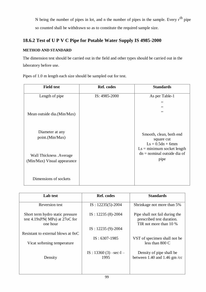
99
N being the number of pipes in lot, and n the number of pipes in the sample. Every rth
pipe
so counted shall be withdrawn so as to constitute the required sample size.
18.6.2 Test of U P V C Pipe for Potable Water Supply IS 4985-2000
METHOD AND STANDARD
The dimension test should be carried out in the field and other types should be carried out in the
laboratory before use.
Pipes of 1.0 m length each size should be sampled out for test.
Field test Ref. codes Standards
Length of pipe
Mean outside dia.(Min/Max)
Diameter at any
point.(Min/Max)
Wall Thickness .Average
(Min/Max) Visual appearance
Dimensions of sockets
IS: 4985-2000
As per Table-1
,,
,,
,,
Smooth, clean, both end
square cut
Ls = 0.5dn + 6mm
Ls = minimum socket length
dn = nominal outside dia of
pipe
ON QUALITY MANAGEMENT AND SURVEILLSYSTEM
Lab test Ref. codes Standards
Reversion test
Short term hydro static pressure
test 4.19xPN( MPa) at 27oC for
one hour
Resistant to external blows at 0oC
Vicat softening temperature
Density
IS : 12235(5)-2004
IS : 12235 (8)-2004
IS : 12235 (9)-2004
IS : 6307-1985
IS : 13360 (3) –sec-I –
1995
Shrinkage not more than 5%
Pipe shall not fail during the
prescribed test duration.
TIR not more than 10 %
VST of specimen shall not be
less than 800 C
Density of pipe shall be
between 1.40 and 1.46 gm /cc

100
Sulphated ash content 11.0 % ( Max.)
18.6.3 Test of Glazed Stone Ware Pipes IS: 651-2007
METHOD AND STANDARDS
The dimension test of pipe should be conducted in the field after the sampling is done by EIC.
Hydraulic and other tests should be got done in the approved laboratory before use. The material
should conform to relevant specifications.
Standards
Field test Ref. codes Standards
1.Dimention
Length
Internal diameter
Mean thickness
Internal depth of socket
Excess shoulder measurement
Length of grooving
2 Hydraulic test
3 Alkali test
4 Other test
(a) Crushing strength
(ii) Absorption
(iii) Acid resistant test
As per
IS: 651-2007
IS: 651-2007
+4%. -1.5%
As per IS: 651-2007 Table 1
Should sustain minimum 0.15 Mpa (1.50
kg/cm2) for 5 seconds
No evidence of pitting, softening, spallting or
cracking should be observed
Internal
dia in mm
SP-1
KN/m
SP-2
KN/m
SP-3
KN/m
Upto 150 16 18 21
200-300 16 21 24
350-450 16 26 32
500-800 16 32 60
Thickness in mm Increase in
mass
Up to 20 6%
Over 20 up to 25 7%
Over 20 up to 32 8%
Over 20 up to 38 9%
Over 38 10%
Loss in mass 2.5 % maximum

101
18.6.4 Test of R.C.C Pipes
METHOD AND STANDARDS
It shall be as per IS: 458-2003 and should also conform the test requirement as per IS: 3597-
1998.
Test Frequency Ref. Code Acceptance/ Standard
1. Tolerances in At the start of work IS: 458- Up to and including 30 mm + 2mm, -1mm
Dimensions for source approval 2003 Over 30 mm and up to and including 50mm
Once for every Lot for + 3mm, - 1.5 mm
Wall Thickness each size Over 50 mm and up to and including 65mm
+ 4mm,- 2.0 mm
Over 65 mm and up to and including 80mm
+ 5mm, - 2.5 mm
Over 80 mm and up to and including 95mm
+ 6mm, - 3.0 mm
Over 95 mm + 7mm, - 3.5 mm
Internal Dia. Of IS: 458- Up to and including 300 mm ± 3mm
pipe or socket 2003 Over 300 mm and up to and including 600
mm ± 5mm
Over 600 mm ± 10 mm
Overall Length
IS: 458- 2003 ±1% of standard Length
2. Three Edge Bearing
IS: 458- 2003 Shall withstand the design Load
3. Water
Absorption
IS : 3597-
1998
After 10 minutes, 2.5 % of dry Mass max. and total absorption at the end of 24 Hours shall not exceed 6.5% of dry mass
4. Hydrostatic Test No leakage under the design pressur
5. Straightness The deviation from straightness when tested
by means of rigid straight edge parallel to the
longitudinal axis of the pipe shall not exceed
3mm for every m length
6. Reinforcement IS: 458- On breaking the Pipe and extracting the
2003 reinforcement, it shall be as per the
Provision

102
18.6.5 Test of HDPE Pipes
METHOD AND STANDARDS
The pipe shall conform to IS: 4984-2016
Test Frequency Ref. code Acceptance / Standard
1.Dimensions
(i) Outside Dia. As per Table
(ii) Wall thickness
1. Hydraulic No localized swelling, leakage, weeping, or
Characteristics bursting during subjecting to internal pressure
creep test.
2. Reversion Test Longitudinal reversion shall not be more than 3%
3. Density 940.5 to 946.4Kg/m3 at 270C and shall not differ
from the nominal value by more than 3kg/ m3
4. Melt Flow Rate 0.41 to 1.10 at 1900C with nominal load of 5kg
(MFR) and shall be within 20% of the value declared by
the manufacturer.
5. Carbon Black
Content and 2.5+ 0.5% with uniform dispersion.
Dispersion

103
18.6.6 Test of G.I. PIPES
METHOD AND STANDARDS
It shall conform to IS: 1239 (I) -2004 with respect to dimension, weight per meter and Hydraulic
Test pressure. The Galvanizing of pipes shall also conform to relevant IS: Codes as given below;
400 g/m2 minimum total mass of Zinc (inside and outside) per surface area (inside and outside) of the coated surface.
The Zinc coating shall be free from imperfection like flux, ash and dross inclusions, bare patches, black spots, pimples, lumpiness, rums, rust, blister, white deposit etc
Test
Frequency
Ref Codes
1. Mass of Zinc One test per lot IS: 6745-1972
Coating
2.Visual Test One test per lot IS: 2629-1985

104
18.7 WATER FOR CONSTRUCTION PURPOSES
Water used for mixing and curing shall be clean and free from injurious amounts of oil,
acids, alkalis, salts, sugar, organic materials or other substances that may be deleterious to
concrete or steel. Potable water is generally considered satisfactory for mixing concrete.
18.7.1 SAMPLING OF WATER
The containers of glass or other inert material like polythene must be carefully cleaned
before use. Minimum one-liter sample should be collected for lab test.
18.7.2 METHOD AND STANDARDS
Water should be tested as per relevant IS Codes as shown below, and shall conform to IS: 456 -
2000 and IS: 10500-1991.
Test Frequency Ref. Codes Acceptance/Standard
1. Chemical Once for every
Analysis source approval IRC: 21-2000
Every Quarterly a) Minimum 6
(a) pH value Chemical tests daily
in the site IS: 3025 (Part 32) - b) 2000mg/L for concrete
Laboratory with 1987 not containing embedded
(b) Chlorides (as testing kits steel and 500mg/L for
Cl)
RCC and PSC
(c) Sulphates (as IS: 3025 (Part 28) c) 400mg/L
SO3) -1987
(d) Neutralization IS: 3025 (Part 22)
d) Max. 5 ml of 0.2 normal
with NaoH (with
-1987
NaOH to neutralize 100
phenolphthalein as
ml. sample of water
indicator)
2. Physical
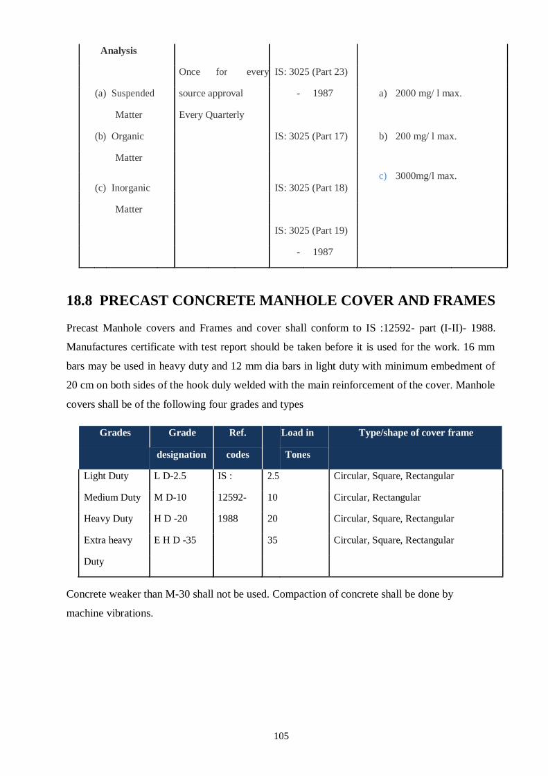
105
Analysis
Once for every IS: 3025 (Part 23)
(a) Suspended source approval - 1987 a) 2000 mg/ l max.
Matter Every Quarterly
(b) Organic IS: 3025 (Part 17) b) 200 mg/ l max.
Matter
c) 3000mg/l max.
(c) Inorganic
IS: 3025 (Part 18)
Matter
IS: 3025 (Part 19)
- 1987
CONTROL MANUAL
18.8 PRECAST CONCRETE MANHOLE COVER AND FRAMES
Precast Manhole covers and Frames and cover shall conform to IS :12592- part (I-II)- 1988.
Manufactures certificate with test report should be taken before it is used for the work. 16 mm
bars may be used in heavy duty and 12 mm dia bars in light duty with minimum embedment of
20 cm on both sides of the hook duly welded with the main reinforcement of the cover. Manhole
covers shall be of the following four grades and types
Grades Grade Ref. Load in Type/shape of cover frame
designation codes Tones
Light Duty L D-2.5 IS : 2.5 Circular, Square, Rectangular
Medium Duty M D-10 12592- 10 Circular, Rectangular
Heavy Duty H D -20 1988 20 Circular, Square, Rectangular
Extra heavy E H D -35 35 Circular, Square, Rectangular
Duty
Concrete weaker than M-30 shall not be used. Compaction of concrete shall be done by
machine vibrations.

106
18.9 PLASTIC ENCAPSULATED FOOTRES
Orange colour safety footrest of minimum 6 mm thick plastic encapsulated as per IS : 10910-
1984 on 12 mm dia. steel bar conforming to IS : 1786-2008 having minimum cross section as 23
mm x 25 mm and overall minimum length 263 mm and width as 165 mm with minimum 112
mm space between protruded legs having 2 mm tread on top surface ribbing or chequering
besides necessary and adequate anchoring projections on tail length on 138 mm as per standard
drawing and suitable to with stand the bend test and chemical resistant test as per specifications
and having manufacturer’s permanent identification mark to be visible even after fixing. The
step shall be tested at a load of 225 Kg. as per IS : 5455 -1969.
18.10 LDPE SHEET
LDPE plastic film shall be made of genuine virgin raw material (polymer) having a density
between 0.913 to 0.923 gm/cm3 at 27
0 C. The film shall have IS certification regarding its
quality as per IS: 2508 – 1984. The film shall be of the specified thickness and shall be supplied
in the form of flat sheet. The length of the single roll shall not be less than 30 M.
18.11 TEST FOR TUBE WELL
18.11.1 WATER SAMPLING
Physical, chemical and bacteriological analyses are necessary for drinking water. All samples of
water should be properly labelled and should be accompanied by complete and accurate
identifying and descriptive data. Data should include date and time of collection, type of source
of the sample and temperature of water at the time of collection.
18.11.2 SAMPLING FOR PHYSICAL AND CHEMICAL ANALYSIS
The containers of glass or other inert material like polythene must be carefully cleaned before
use. It can be rinsed with alkaline permanganate solution followed by oxalic acid solution. After
having been cleaned, should be rinsed thoroughly with tap water and then with distilled water.
About 2.5 liters of the sample is required for analysis. Prior to filing, the sample bottle should be
rinsed out two or three times with water to be collected. Care should be taken to obtain a sample
that is truly representative of existing conditions and to handle it in such a way that it does not
deteriorate or become contaminated before it reaches the laboratory. The sample should reach
the place of analysis as quickly as possible within 72 hours of collection. The sample should
only be collected after the well has been pumped for a sufficient time to ensure that the sample
will be representative of the ground water.

107
18.11.3 SAMPLING FOR BACTERIOLOGICAL ANALYSIS
Sterilized glass bottles provided with round glass stopper having an overlapping rim should be
used. The stopper and the neck of the bottle should be protected by brown paper. The
sterilization is carried out in an autoclave at 1 kg/cm2 pressure for 15 minutes or by dry heat at
1600 C for 1 hour. The sample should be representative of the water to be tested and they should
be collected with utmost care to ensure that no contamination occurs at the time of collection or
prior to examination. The sample bottle should not be opened till the time of filling. The stopper
with the cap should be removed with care to eliminate soiling. During sampling, the stopper and
the neck of the bottle should not be touched by hand and they should be protected from
contamination. The bottle should be held near the base, filled without rinsing and the stopper
replaced immediately. The bottle should not be filled completely but sufficient air space left for
shaking before analysis. Then the brown paper warping should be tied to protect the sample from
contamination. The volume of the sample should be sufficient for carrying out all the tests
required and in no case; it should be less than 250 ml.
Recommended Guidelines for Physical and Chemical Parameters as Per Water Manual (Govt. of India) As Per BISN
Sl. No. Characteristics *Acceptable **Cause for rejection
1 Turbidity (NTU) 1 10
2 Colour (Units on Platinum Cobalt
scale)
5 25
3 Taste and Odour Unobjectionable Unobjectionable
4 pH 7.0 to 8.5 <6.5 or> 9.2
5 Total dissolve solids (mg/I) 500 2000
6 Total hardness (as CaCO3) (mg/I) 200 600
7 Chlorides (as CI) (mg/I) 200 1000
8 Sulphates (as SO4) (mg/I) 200 400
9 Fluorides (as F) (mg/I) 1.0 1.5
10 Nitrates (as NO3) (mg/I) 45 45
11 Calcium (as Ca) (mg/I) 75 200
12 Magnesium (as Mg) (mg/I) ≤30 150
13 Iron (as Fe) (mg/I) 1.0 1.0
14 Manganese (as Mn) (mg/I) 0.05 0.5
15 Copper (as Cu) (mg/I) 0.05 1.5
16 Aluminium (as AI ) (mg/I) 0.03 0.2
17 Alkalinity (mg/I) 200 600
18 Residual Chlorine (mg/I) 0.2 >1.0

108
19 Zinc (as Zn ) (mg/I) 5.0 15.0
20 Phenol compounds (as Phenol) 0.001 0.002
21 Anionic detergents (as MBAS ) (mg/I) 0.2 1.0
22 Mineral Oil (mg/I) 0.01 0.03
23 Arsenic (as As ) (mg/I) 0.01 0.05
24 Cadmium (as Cd ) (mg/I) 0.01 0.01
25 Chromium (as hexavalent Cr ) (mg/I) 0.05 0.05
26 Cyanides (as CN ) (mg/I) 0.05 0.05
27 Lead (as Pb ) (mg/I) 0.05 0.05
28 Selenium (as Se ) (mg/I) 0.01 0.01
29 Mercury (total as Hg ) (mg/I) 0.001 0.001
30 Polynuclear aromatic hydrocarbons
(PAH) (μg/I)
0.2 0.2
31 Pesticides (total, mg/I) Absent Refer to WHO
guidelines for
drinking water
Quality Vol. I-1993
32. Gross Alpha activity (Bq/I) 0.1 0.1
33. Gross Beta activity (Bq/I) 1.0 1.0
STRUCTION QUALITY MANAGEMENT AND E SYSTEM QUALITY ASSURANCUALITY CONTROL
MANUA
Notes:
* The figures indicated under the column “Acceptable” are the limits up to which water is generally acceptable to the consumers. * ** Figures in excess of those mentioned under “Acceptable “render the water not acceptable , but still may tolerated in the absence of an alternative and batter source but up to the limits indicated under column “ Cause for Rejection” above which the have to be rejected.
+ It is possible that some mine and spring waters may exceed these radioactive limits and in such cases it is necessary to analyze the individual radio nuclides order nuclides order to assess the acceptability or otherwise for public consumption.
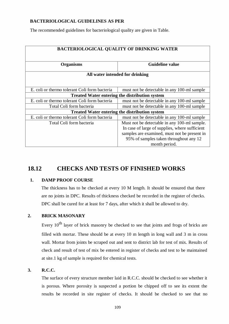
109
BACTERIOLOGICAL GUIDELINES AS PER
The recommended guidelines for bacteriological quality are given in Table.
BACTERIOLOGICAL QUALITY OF DRINKING WATER
Organisms Guideline value
All water intended for drinking
E. coli or thermo tolerant Coli form bacteria must not be detectable in any 100-ml sample
Treated Water entering the distribution system
E. coli or thermo tolerant Coli form bacteria must not be detectable in any 100-ml sample
Total Coli form bacteria must not be detectable in any 100-ml sample
Treated Water entering the distribution system
E. coli or thermo tolerant Coli form bacteria must not be detectable in any 100-ml sample
Total Coli form bacteria Must not be detectable in any 100-ml sample.
In case of large of supplies, where sufficient
samples are examined, must not be present in
95% of samples taken throughout any 12
month period.
18.12 CHECKS AND TESTS OF FINISHED WORKS
1. DAMP PROOF COURSE
The thickness has to be checked at every 10 M length. It should be ensured that there
are no joints in DPC. Results of thickness checked be recorded in the register of checks.
DPC shall be cured for at least for 7 days, after which it shall be allowed to dry.
2. BRICK MASONARY
Every 10th
layer of brick masonry be checked to see that joints and frogs of bricks are
filled with mortar. These should be at every 10 m length in long wall and 3 m in cross
wall. Mortar from joints be scraped out and sent to district lab for test of mix. Results of
check and result of test of mix be entered in register of checks and test to be maintained
at site.1 kg of sample is required for chemical tests.
3. R.C.C.
The surface of every structure member laid in R.C.C. should be checked to see whether it
is porous. Where porosity is suspected a portion be chipped off to see its extent the
results be recorded in site register of checks. It should be checked to see that no
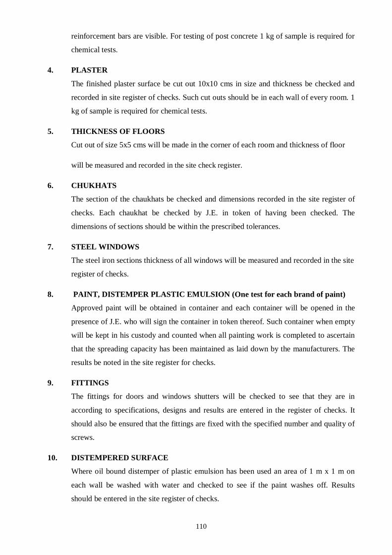
110
reinforcement bars are visible. For testing of post concrete 1 kg of sample is required for
chemical tests.
4. PLASTER
The finished plaster surface be cut out 10x10 cms in size and thickness be checked and
recorded in site register of checks. Such cut outs should be in each wall of every room. 1
kg of sample is required for chemical tests.
5. THICKNESS OF FLOORS
Cut out of size 5x5 cms will be made in the corner of each room and thickness of floor
will be measured and recorded in the site check register.
6. CHUKHATS
The section of the chaukhats be checked and dimensions recorded in the site register of
checks. Each chaukhat be checked by J.E. in token of having been checked. The
dimensions of sections should be within the prescribed tolerances.
7. STEEL WINDOWS
The steel iron sections thickness of all windows will be measured and recorded in the site
register of checks.
8. PAINT, DISTEMPER PLASTIC EMULSION (One test for each brand of paint)
Approved paint will be obtained in container and each container will be opened in the
presence of J.E. who will sign the container in token thereof. Such container when empty
will be kept in his custody and counted when all painting work is completed to ascertain
that the spreading capacity has been maintained as laid down by the manufacturers. The
results be noted in the site register for checks.
9. FITTINGS
The fittings for doors and windows shutters will be checked to see that they are in
according to specifications, designs and results are entered in the register of checks. It
should also be ensured that the fittings are fixed with the specified number and quality of
screws.
10. DISTEMPERED SURFACE
Where oil bound distemper of plastic emulsion has been used an area of 1 m x 1 m on
each wall be washed with water and checked to see if the paint washes off. Results
should be entered in the site register of checks.

111
11. GLASS PANES
The thickness of 5% of the glass panes to be fixed will be checked with calipers and
recorded in the site register of checks. It should also be seen that the panes are fixed with
specified number and quality of screws.
12. SAL WOOD FOR CHAUKHATS
No individual hard and sound knot shall be more than 2.5 cm diameter and the aggregate
area of all knots shall not exceed 1% area of the piece. There shall not be less than 5
growth rings per 2 cm width. Air dry wood shall weight at an average of about 0.8 to 0.9
gms / Cm3.
13. TIMBER FOR SHUTTERS
No individual hard and sound knot shall be more than 2.5 cm diameter and the aggregate
area of all knots shall not exceed 1% area of the piece. Air dry wood shall weight at an
average of about 0.56 gms / Cm3.
14. THICKNESS OF SHUTTERS
The thickness of all the shutters shall be measured with calliper and recorded in the site
register of checks. The thickness of shutters shall be within the prescribed tolerances.
18.13 MANDATORY TESTS
Quality Control is defined as conformity to the specification, no more, no less. The most
practical method of effective Quality Control is to check what is done in totality to conform to
the specification. The Quality Control is a corporate, dynamic program to assure that all the
aspects of materials, equipments and workmanship are well looked after. Quality control
requires carrying out testing of material at regular interval during the execution of works. The
list of mandatory tests required for different items are given in the following table.

112
Table: 18.1 Material Testing Standard & Frequency
Sl. No. Name of Test Reference Frequency Mini.
Standard
s
material Codes Samp.
size
1 2 3 4 5 6 8
1 MORTAR
1.1 Water (i)PH value IS : 3025- Water from each One liter > 6
1987 source shall be got
Max. 5 ml
(ii)Limits of
tested before the
of 0.02
Acidity
commencement of
NaoH in
work and
100 ml
(iii)Limits of
thereafter once in
water.
Alkality
every 3 months till
Max. 25
the completion of
ml of 0.02
work. Water from H2SO4 in
municipal source 100 ml
need be tested water
(iv)Percentage of once in 6 months.
solids Number of tests for
a)2000
(a)Chlorides each source shall
be 3 mg/l PCC
500 mg/l
(b)Suspended
RCC
b)2000
matter

113
TRUCTION QUALITY MANAGEMENT AND SURVEILLAM QUTY ASSURAN
CE QUALITY CONTROL MANUAL
mg/l Max.
( c) Sulphates
c)400
(d)Inorganic
mg/l
d)3000
solids mg/l Max.
e)200
(e)Organic solids mg/l
1.2 Cement (a)Physical Every 10 tonnes or 10 Kg
requirement IS : 4031- part thereof. Each i)Not >
(i)Fineness
1988
brand of cement
10%
ii)10mm
(ii)Soundness
brought to site
Max.
shall be tested as
iii)Initial 30
(iii)Setting
per this frequency.
mint.
time(Initial & minimum
Final) Final 600
(iv)Compressive
mint.Max.
iv) > 43
strength
Mpa
(v)Consistency of
standard cement
paste

114
Sl. Name of Test Reference Frequency Mini. Stand-
No. material Codes Samp. ards
size
1 2 3 4 5 6 8
1.3 Sand (a)Organic IS : 2386- Every 20 cum or 2 Kg As per IS
Impurities 1963 part thereof or : 383-
(b)Silt content more frequently as
1970
( c)Particle size decided by EIC
Max. 8%
Distribution
As per IS
(d)Bulking of
: 383-
Sand
1970
2 CONCRETE WORK
2.1 Stone (a) Percentage of Is :2386- Every 40 cum or 6.5 Kg a)Max .5%
aggregate soft or deleterious 1963 part thereof or
Material more frequently as
As per IS:
(b)Particle size
decided by EIC
383 -1970
( c)Organic
Impurities
(d)Surface
Moisture
(e)Determination
e)Not less
of 10% fine value
than 5T
(f)Specific gravity
(g)Bulk density
(h)Crushing h,i) 45%

115
Strength Max.
(i)Impact value 30% for
wearing
surface
2.2 Concrete Slump test IS :516- 15 cum or part As As per
1959 thereof directed grade
by EIC
3 R.C.C. WORK
3.1 Concrete (a)Cube test IS :516- 1-5 m 3 - 1 sample As As per
1959 6-15 m3 - 2 sampl directed Grade.
16-30 m3 - 3 by EIC
sampl
(b)Slump test 31-50 m3- 4
sampl
As and when reqd.
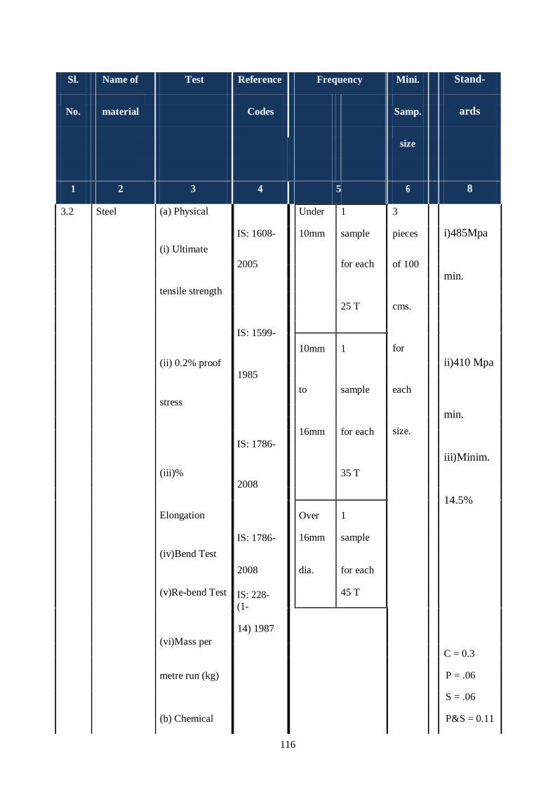
116
Sl. Name of Test Reference Frequency Mini. Stand-
No.
material
Codes
Samp.
ards
size
1 2 3 4 5 6 8
3.2 Steel (a) Physical Under 1 3
(i) Ultimate
IS: 1608- 10mm sample pieces i)485Mpa
2005
for each
of 100
min.
tensile strength
25 T
cms.
IS: 1599-
for
(ii) 0.2% proof
10mm
1
ii)410 Mpa
1985
to
sample
each
stress
min.
size.
16mm
for each
IS: 1786-
iii)Minim.
(iii)%
2008
35 T
14.5%
Elongation
Over
1
(iv)Bend Test
IS: 1786- 16mm sample
2008
dia.
for each
(v)Re-bend Test IS: 228- (1-
45 T
(vi)Mass per
14) 1987
C = 0.3
metre run (kg) P = .06
(b) Chemical
S = .06
P&S = 0.11
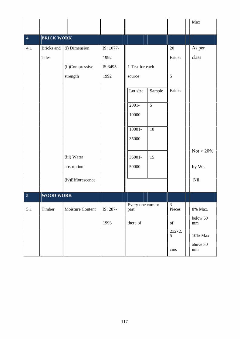
117
Max
4 BRICK WORK
4.1 Bricks and (i) Dimension IS: 1077- 20 As per
Tiles 1992 Bricks class
(ii)Compressive IS:3495- 1 Test for each
strength 1992 source 5
Bricks
Lot size Sample
2001- 5
10000
10001- 10
35000
Not > 20%
(iii) Water
35001-
15
absorption 50000 by Wt.
(iv)Efflorescence
Nil
5 WOOD WORK
5.1 Timber Moisture Content IS: 287-
Every one cum or part
3 Pieces 8% Max.
1993 there of of below 50 mm
2x2x2.5 10% Max.
cms
above 50 mm

118
Sl. Name of Test Reference Frequency Mini. Stand-
No. material Codes Samp. ards
size
1 2 3 4 5 6 8
6 STRUCTURAL STEEL IS : 8910-2010
6.1 Structural (a)Tensile IS:1599- Every 20 T or part 1 No.
steel Strength 1985 there of 0.5 mt
(b) Bend Test length
6.2 Tubular (a)Tensile Test IS:1608- Every 8 T or part 1 Piece
pipes (b) Bend Test 2005 there of of 1m
(C )Flattening Test IS: 2329- length
2005 for each
IS:2328- size
2005
7 Hydro testing of sewers
7.1 Testing of Leakage As per On completion of -
M.H. manual M.H.
chambers
7.2 Pipe Leakage As per Between every 2 -
sewer laid manual M.H.
8 Hydro testing of pipeline
8.1 Pipe line Pressure Testing As per At each running bill -
laid Manual / specifications

119
18.14 HYDROSTATIC TESTS OF PIPELINES
After a new pipe has been laid, jointed and back filled (or any valved section thereof), it
shall be subjected to the following two tests:
Pressure test at a pressure of at least double the maximum working pressure-pipe and joints
shall be absolutely water tight under the test.
Leakage test (to be conducted after the satisfactory completion of the pressure test) at a
pressure to be specified by the authority for duration of two hours.
The portions of the line shall be tested by subjecting to pressure test as the laying
progresses before the entire line is completed. In this way any error of workmanship will be
found immediately and can be corrected at a minimum cost. Usually the length of the
section to be tested shall not exceed 500m.
Where any section of a main is provided with concrete thrust blocks or anchorages, the
pressure test shall not be made until at least five days have elapsed after the concrete is cast.
If rapid hardening cement has been used in these blocks or anchorages, test shall not be
made until at least two days have elapsed.UAL
Prior to testing, enough back fill shall be placed over the pipe line to resist upward thrust. All
thrust blocks forming part of the finished line shall have been sufficiently cured and no
temporary bracing shall be used.
The open end of the section shall be sealed temporarily with an end cap having an outlet
which can serve as an air relief vent or for filling the line, as may be required. The blind face
of the end cap shall be properly braced during testing by screw jacks and wooden planks or
steel plate.The section of the line to be tested shall be filled with water manually or by a low
pressure pump. Air shall be vented from all high spots in the pipe line before making the
pressure strength test because entrapped air gets compressed and causes difficulty in raising
the required pressure for the pressure strength test
The test pressure shall be gradually raised at the rate of approximately one Kg,/sq. cm. /min.
the duration of the test period if not specified shall be sufficient to make a careful check on
the pipe line section.

120
The pipe shall be judged to have passed the test satisfactorily if the quantity of water required
to restore the test pressure does not exceed 1.5 liters per 10 mm of nominal bore for a length
of 1 km.
18.15 TEST REPORT FORMATS
All the test report formats for implementation of QA/QC procedures are given in Appendix.
Test Certificate for Cement
Test Certificate for Coarse Aggregate
Test Certificate for fine Aggregate
Test Certificate for water (where water is brackish)
Compressive Strength of Concrete
Concrete Slump Test
Hydrostatic Test for NP Pipes
Hydrostatic Test for pressure Pipes
Leak Test for Under Ground RCC Structures
Leak Test for Elevated RCC Structures
Water absorption of bricks
Silt content of fine aggregates
18.16 BRANDS OF MATERIAL AND EQUIPMENTS
The detailed specifications of material and works are not in the preview of QA/QC manual,
as these are already available with Department and the tender/ bids are invited as per these
technical specifications.
For quality of goods/equipments, ISI marked or other reputed brand or equivalent standards
shall be acceptable for works. However, the obligatory tests for quality assurance shall have
to be conducted in both the cases.

121
For the small value of works the routine testing shall be limited only to physical parameters
such as;
Sieve analysis
Dia of pipe
Thickness of pipe
Mass of pipe and steel per meter.
Visual/dimension/absorption/ efflorescence test of bricks
Silt content of fine aggregate

122

123
APPENDICES
(To be filled in by PIU)

124
APPENDIX-A
CHECKLIST GUIDE FOR
WORKS

125

I
APPENDIX A
S.No Form of Work Description
1 Tube well
A/CL1
2 Laying and jointing of pipe line, back
filling, hydro testing.
A/CL2
3 Pumping machinery & fittings of
delivery pipe in pump chamber (Tube
well based scheme)
A/CL3
4 Disinfecting plant.
A/CL4
5 Pump chamber.
A/CL5
6 Development of water works.
A/CL6
7 O.H.S.R
A/CL7
8 Water treatment plant
A/CL8
9 Control panel for 3 phase pump &
motor.
A/CL9
10 Submersible Pump / VT
pump/Centrifugal pump, motor &
fittings of delivery pipe in pump
chamber
A/CL10
11 Control Panel for Single Phase Motor &
Pump
A/CL11
12 Water Treatment Unit
A/CL12
13 Steel Staging for Water Tanks
A/CL13
14 Rotational Moulded Polyethylene Water
Storage Tanks
A/CL14
15 Quality certificate.
A/CL15

II
FORM No. A/CL-1
CHECK LIST FOR TUBEWELL
1. Name of work:
2. Contract Agreement No.:
3. Name of contractor:
S.No Description Yes/No/NA Remarks
1 Whether tube well site is prone to
flooding and free from filled up earth?
2 Whether any village pond is located
adjacent to water works site?
3 Whether the drilling point of tube well
is as per approved lay out plan?
4 Whether Geologist/Hydrologist has
been engaged for installation of tube
well?
5 Whether the type of drilling, size of
tube well boring is as per contract
agreement?
6 Whether samples of strata were
collected accurately and kept in boxes
for further analysis?
7
Whether the gravel size is as per
specification
8 Whether M.S. Pipes used are of proper
thickness, free from rust and with
bituminous painted as per approved
specification, Test certificate obtained
and Departmental inspection
conducted?
9 Whether strainers are of proper
thickness, and as per approved
specifications, Test certificate
obtained and Departmental inspection
conducted?
10 Whether the tube well assembly has
been approved?
11 Whether lowering of tube well
assembly has been done in the
presence of:
AE/JE (for ward level scheme)
EE/AE (For rest other Scheme)
Note: Lower Authority shall copy the
necessary approval to the immediate Higher
Authority

III
12 Whether Cement/clay, seal plug is
provided between the annular spaces
of boring & lowering assembly to
prevent contamination of good quality
water bearing strata as per
specification
13 Whether certificate to the effect that
“Certified that the lowering of the pipe
assembly and screen/ strainer has been
done in our presence and that the
quality, sizes and length of pipes and
screen/strainer are as per record / entry
made and are correctly located and
lowered in the Bore” has been
recorded include in format and is duly
signed by AE–in-charge & AE
deputed for lowering from other
division and duly countersigned by the
Executive Engineer- in-charge?
14 Whether capacity of Air Compressor
(Both CFM and PSI)
used is as per specifications given in
bid document
15 Whether capacity of pumping set used
for development is sufficient w.r.to
developed and designed discharge?
16 Whether tube well development
hours are as per contract and log
book maintained?
a) With compressor
b) With pumping set
17 Whether running hours of air
compressor and submersible pumping
set are witnessed and certified by
authorized officer of PIU?
18 Whether yield test of tube well done &
recorded?
19 Whether strata chart and assembly
chart showing all details of tube well
has been submitted by contactor to
PIU?

IV
20 Whether result of water sample tests
(Physical/Chemical/ Biological/
Bacteriological Examination) after
development with pumping set are
conforming to drinking water
standards?
For Contractor For Department
Signature…. Signature….
Name. Name….
Date… Date….

V
FORM No. A/CL-2
CHECK LIST FOR LAYING AND JOINTING OF PIPE LINE, BACK FILLING,
HYDRO TESTING
1. Name of work:
2. Contract Agreement No.:
3. Name of contractor:
S.N Description Yes/No/NA Remarks
A. Supplying of pipe and valves, excavation, laying, jointing, and fixing of valves.
1 a) Whether pipes are of proper
specifications and as per contract
agreement?
A) Whether pipes have been tested at
manufacturer’s premises and submitted
with inspection note along with test
reports?
2 Whether the Sluice Valve/Air Valves etc.
are as per specification?
3 Whether the
MS/DICI/GI/UPVC/HDPE/MDPE/CPVC
specials are as per specification?
4 Whether the trenches have been excavated
to correct depth as per specifications and
dimensions?
5 Whether the pipe line has been laid true to
the alignment with proper bedding made as
per specifications?
6 Whether Jointing material used as per
specification?
7 Whether all the lanes are provided with
pipe lines as per approved drawing?
8 Whether the completion drawing of laid
pipe line prepared and submitted with
running bills?
B. Completion, testing and commissioning.
1 Any busting of pipeline noticed in the
village.
2 Whether all the leakages observed during
testing have been repaired properly?
3 Whether the trenches were backfilled
properly and consolidated as per
specifications?
4 The filling is carried out to required level
and without any settlement?

VI
5 Whether the road metal was separately
collected and all type of roads reinstated
properly after laying of pipes?
6 Whether the valve chambers constructed as
per drawing and tested for water tightness?
7 Whether the distribution system
hydraulically tested?
8 Whether the distribution system properly
disinfected before providing connections to
consumers?
For Contractor For Department
Signature…. Signature….
Name. Name….
Date… Date….
Date….
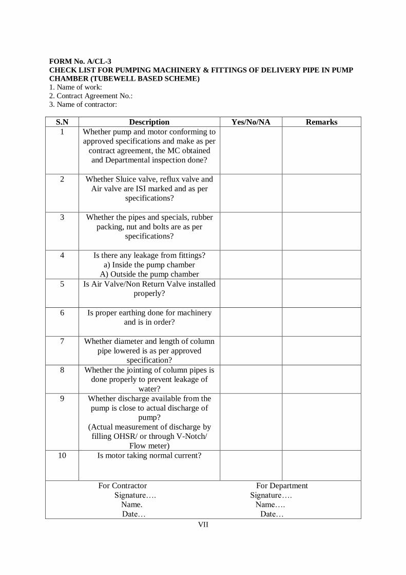
VII
FORM No. A/CL-3
CHECK LIST FOR PUMPING MACHINERY & FITTINGS OF DELIVERY PIPE IN PUMP
CHAMBER (TUBEWELL BASED SCHEME) 1. Name of work:
2. Contract Agreement No.: 3. Name of contractor:
S.N Description Yes/No/NA Remarks
1 Whether pump and motor conforming to
approved specifications and make as per
contract agreement, the MC obtained
and Departmental inspection done?
2 Whether Sluice valve, reflux valve and
Air valve are ISI marked and as per
specifications?
3 Whether the pipes and specials, rubber
packing, nut and bolts are as per
specifications?
4 Is there any leakage from fittings?
a) Inside the pump chamber
A) Outside the pump chamber
5 Is Air Valve/Non Return Valve installed
properly?
6 Is proper earthing done for machinery
and is in order?
7 Whether diameter and length of column
pipe lowered is as per approved
specification?
8 Whether the jointing of column pipes is
done properly to prevent leakage of
water?
9 Whether discharge available from the
pump is close to actual discharge of
pump?
(Actual measurement of discharge by
filling OHSR/ or through V-Notch/
Flow meter)
10 Is motor taking normal current?
For Contractor For Department
Signature…. Signature….
Name. Name….
Date… Date…

VIII
FORM No. A/CL-4
CHECK LIST FOR DISINFECTING PLANT 1. Name of work:
2. Contract Agreement No.:
3. Name of contractor:
S.No Description Yes/No/NA Remarks
CHLORINATOR
1 Whether chlorinator and accessories is as per
specification?
2 Whether MC has been obtained?
3 Whether the chlorinator is installed and working
properly?
4 Whether Testing kit for residual chlorine test available
for water sample testing?
For Contractor For Department
Signature…. Signature….
Name. Name….
Date… Date…

IX
FORM No. A/CL-5
CHECK LIST FOR PUMP CHAMAER
1. Name of work:
2. Contract Agreement No.:
3. Name of contractor:
S.N Description Yes/No/NA Remarks
1 Whether bench Mark pillars are
fixed and layout is correct as per
approved drawing for excavation of
foundation?
2 Whether Depth of foundation is
correct as per approved drawing?
3 Whether Earth bedding condition
checked?
4 Whether following materials used
are as per specifications and Test
for materials conducted as per
frequency?
I. Bricks
II. Fine aggregate
III. Coarse aggregate
5 Whether following manufactured
materials used are as per
specification?
I. Cement
II. Steel for reinforcement
6 Whether Concrete bedding laid as
per specification?
7 Whether proper arrangement of
curing and curing period maintained
as per specification?
8 Whether brick work in foundation
and plinth is as per specifications?
9 Whether Horizontal / vertical
D.P.C. provided as per
specifications?
10 Whether brick work in super
structure is as per specifications and
proper wet bricks are used?
11 Whether brick work in super
structure is in true plumb and top of
all walls are in level?

X
12 Whether Thickness of joints in
brickwork is kept 1 cm± 20 %?
13 Whether All horizontal and vertical
joints are being filled correctly?
14 Whether proper curing period
maintained as per specification?
15 Whether size of doors/windows and
other joinery work as per
specification?
16 Whether proper section of
chowkhats has been provided with
proper grouting as per
specification?
17 Whether Proper Centering and
shuttering has been provided for
R.C.C. slab?
18 Whether steel Reinforcement laid as
per design and drawing?
19 Whether R.C.C. Slab is laid of
required thickness and in level?
20 Whether proper size of Girder
(proper I-section) has been provided
(Medium weight)?
21 Whether proper size of opening in
the roof has been provided with
cover as per drawing for lowering
of pump?
22 Whether surface cleaned of all loose
mortar and efflorescence before
plastering?
23 Is the finishing of plaster
inside/outside is proper and mix is
as per required proportion?
24 Whether the floor has been laid in
panels, correct thickness and proper
sand filling done under floor?
25 Whether proper underground
conduit for electric cable has been
provided for machinery etc as per
drawing & specification?

XI
26 Whether electrical fixtures installed
are as per approved specifications
and quantity?
27 Whether top finishing and slope of
floor is correct?
28 Whether proper tile terracing/lime
terracing has been done on roof as
per specification as per provision
for the contract?
29 Whether proper quality and type of
wood has been used with correct
thickness of shutters as per
specification?
30 Whether thickness of Glass used in
window panes is correct as per
specification?
31 Have grills been provided as per
standard drawings?
32 Whether Quality of
distemper/cement based paint
(Snowcem) is as per specification?
33 Whether Quality of paint used on
wood work/steel work and on other
components is as per specification?
For Contractor For Department
Signature…. Signature…...
Name. Name….
Date… Date…

XII
FORM No. A/CL-6
CHECK LIST FOR DEVLOPMENT OF WATER WORKS
1. Name of work:
2. Contract Agreement No.:
3. Name of contractor:
S.N Description Yes/No/Na Remarks
1 Whether bench Mark pillars are fixed and layout
is correct as per approved drawing for excavation
of foundation?
2 Whether Depth of foundation is correct as per
approved drawing?
3 Whether Earth bedding condition checked?
4 Whether following materials used are as per
specifications?
Bricks
Fine aggregate
Coarse aggregate
5 Whether following manufactured materials used
are as per specification?
Cement
Structural steel
6 Whether Concrete bedding laid as per
specification?
7 Whether brick work in foundation and plinth is as
per specifications?
8 Whether D.P.C. provided as per specifications?
9 Whether brick work in super structure is as per
specifications and proper wet bricks are used?
10 Whether brick work in super structure is in true
plumb and top of all pillars in level?
11 Whether Thickness of joints in brickwork is kept
1 cm± 20 %?
12 Whether All horizontal and vertical joints are
being filled correctly?
13 Whether proper curing period maintained as per
specification?
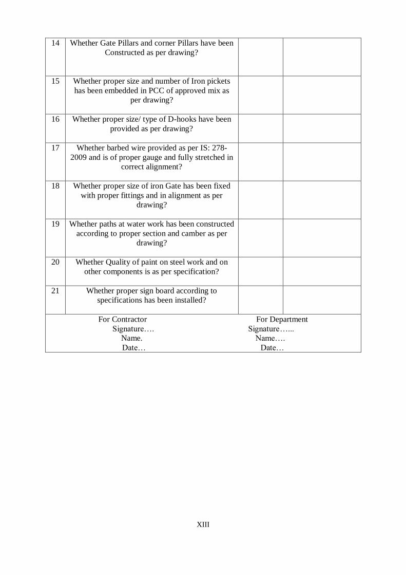
XIII
14 Whether Gate Pillars and corner Pillars have been
Constructed as per drawing?
15 Whether proper size and number of Iron pickets
has been embedded in PCC of approved mix as
per drawing?
16 Whether proper size/ type of D-hooks have been
provided as per drawing?
17 Whether barbed wire provided as per IS: 278-
2009 and is of proper gauge and fully stretched in
correct alignment?
18 Whether proper size of iron Gate has been fixed
with proper fittings and in alignment as per
drawing?
19 Whether paths at water work has been constructed
according to proper section and camber as per
drawing?
20 Whether Quality of paint on steel work and on
other components is as per specification?
21 Whether proper sign board according to
specifications has been installed?
For Contractor For Department
Signature…. Signature…...
Name. Name….
Date… Date…

XIV
FORM No. A/CL-7
CHECK LIST FOR OHSR
1. Name of work:
2. Contract Agreement No.:
3. Name of contractor:
S.N Description Yes/No/NA Remarks
1 Is Soil bearing Capacity has been got
checked from approved/ reputed
institute?
2 Whether bench Mark pillars and center
pillar were fixed and layout/depth of
foundation is correct as per approved
drawing?
3 Earth bedding condition checked for
any filled up soil.
4 Is suitable mechanical arrangement for
curing of RCC work (electrical
motor/diesel engine operated device) is
available at site which is capable of
lifting water up to top dome of OHSR.?
5 Whether following materials used are
as per specifications?
Fine aggregate
Coarse aggregate
6 Whether following manufactured
materials used are as per
specifications?
Cement
Steel for reinforcement
7 Whether all requisite tests have been
conducted for the following items as
per frequency?
Excavation and bedding
Plain cement concrete
R.C.C. (Slump test, Compressive
strength)
8 Whether PCC laid as per drawing and
specifications?
9 Whether proper steel centering and
dent less shuttering is being used?

XV
10 The reinforcement in the following
members provided is as per
drawing/design and whether it has been
checked by EE/AE/JE?
Foundation
Columns
Braces
Landings
11 Whether Concrete Mixer/Vibrator was
used at site and standby arrangement
made?
12 Whether R.C.C. in the following
members laid as per dimensions given
in approved drawing with desirable
smooth finishing?
Foundation
Columns
braces
13 Whether verticality of R.C.C. columns
checked before and after pouring of
concrete?
14 Whether proper curing period
maintained as per specification?
1 Is the reinforcement in the following
members provided is as per
drawing/design and whether it has been
checked by EE/AE?
Bottom Ring beam
Bottom dome and gallery
Tank wall
Top ring beam
Top dome
Staircase and landings
2 Whether R.C.C. in the following
members laid as per dimensions given
in approved drawing with desirable
smooth finishing?
Bottom Ring beam
Bottom dome and gallery
Tank wall
Top ring beam
Top dome
Staircase and landings

XVI
3 In Stair Case whether G.I. Pipe railing
and angle iron pickets is as per drawing
and specification?
4 Whether bell Mouth Puddle collars,
Double Flanged Puddle Collars have
been fixed in position and are of proper
specifications and approved make?
5 Whether proper curing period
maintained as per specification?
C. Arrangement and erection of C.I D/F pipe and specials, all balance work including
plinth protection, automatic water level controller and testing of structure etc.
1 Whether the CI/ DI/ DF pipes are as
per specifications and MC obtained and
pipes have been fixed in true plumb?
2 Whether inlet and overflow pipes have
been properly installed in the tank so as
to ensure proper working depth of
OHSR and a free board of 0.60 mtr.?
3 Whether following C.I. valves, specials
have been fixed in position and are of
proper specifications and approved
make?
3.1 Duck Foot bends (IS 13382-1992)
3.2 Sluice Valves
3.3 Expansion Joints (IS 1536-1989)
3.4 M.S. Clamps
3.5 Joining Material (Nut bolts/Rubber
insertion
4 Is pipes extended Ay 2.75 mtr. Length
beyond Duck Foot bends?
5 Is overflow pipe further extended by
providing D/F bend at its end and
vertical pipe of 2 mtr. Length and a
D/F bend duly fitted with
expanded metal mesh of 10 mm sq.
provided at end?
6 Whether angle posts are painted in two
coats after primer?
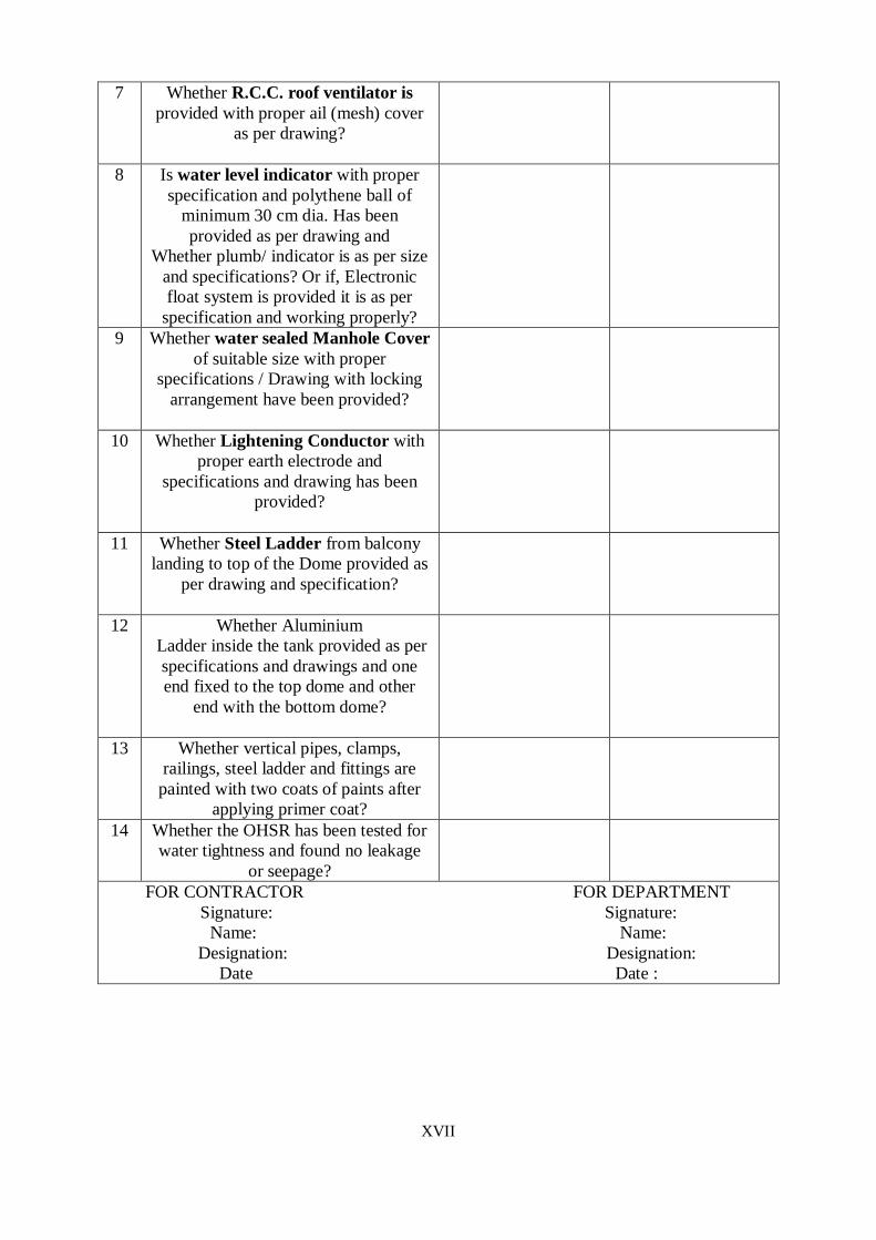
XVII
7 Whether R.C.C. roof ventilator is
provided with proper ail (mesh) cover
as per drawing?
8 Is water level indicator with proper
specification and polythene ball of
minimum 30 cm dia. Has been
provided as per drawing and
Whether plumb/ indicator is as per size
and specifications? Or if, Electronic
float system is provided it is as per
specification and working properly?
9 Whether water sealed Manhole Cover
of suitable size with proper
specifications / Drawing with locking
arrangement have been provided?
10 Whether Lightening Conductor with
proper earth electrode and
specifications and drawing has been
provided?
11 Whether Steel Ladder from balcony
landing to top of the Dome provided as
per drawing and specification?
12 Whether Aluminium
Ladder inside the tank provided as per
specifications and drawings and one
end fixed to the top dome and other
end with the bottom dome?
13 Whether vertical pipes, clamps,
railings, steel ladder and fittings are
painted with two coats of paints after
applying primer coat?
14 Whether the OHSR has been tested for
water tightness and found no leakage
or seepage?
FOR CONTRACTOR FOR DEPARTMENT
Signature: Signature:
Name: Name:
Designation: Designation:
Date Date :

XVIII
FORM No. A/CL-8
CHECK LIST FOR WATER TREATMENT PLANT (SURFACE WATER AASED) 1. Name of work:
2. Contract Agreement No.:
3. Name of contractor:
S.N Description Yes/No/NA Remarks
1 Whether bench mark Pillars constructed for every
units and the foundation, invert, hydraulic and
formation levels have been ensured as per drawing?
2 Whether following materials used are as per
specifications? Whether Test for materials conducted
as per frequency?
Bricks
Fine aggregate
Coarse aggregate
Filter media
3 Whether following manufactured materials used are
as per specifications? Whether requisite Tests for
materials conducted and MC obtained?
Cement
Steel for reinforcement
LDPE sheet
Manhole cover and Footrest
Vent pipes
4 Whether all requisite tests have been conducted for
the following items as per frequency?
Excavation and bedding
Plain cement concrete
Cement Mortar
R.C.C. (Slump test, Compressive strength
5 Whether Intake chamber has been constructed as per
drawing with screen?
6 Whether the sedimentation cum storage tank has been
constructed to correct dimensions as per drawing/
specifications and tested for water tightness?
Whether the float arm has been provided as per
drawing /specification and working properly?
7 Whether the scour cum suction well has been
constructed to correct dimensions as per drawing/
specifications and tested for water tightness?
8 Whether the high level tank has been constructed to
correct dimensions as per drawing/ specifications and
tested for water tightness?
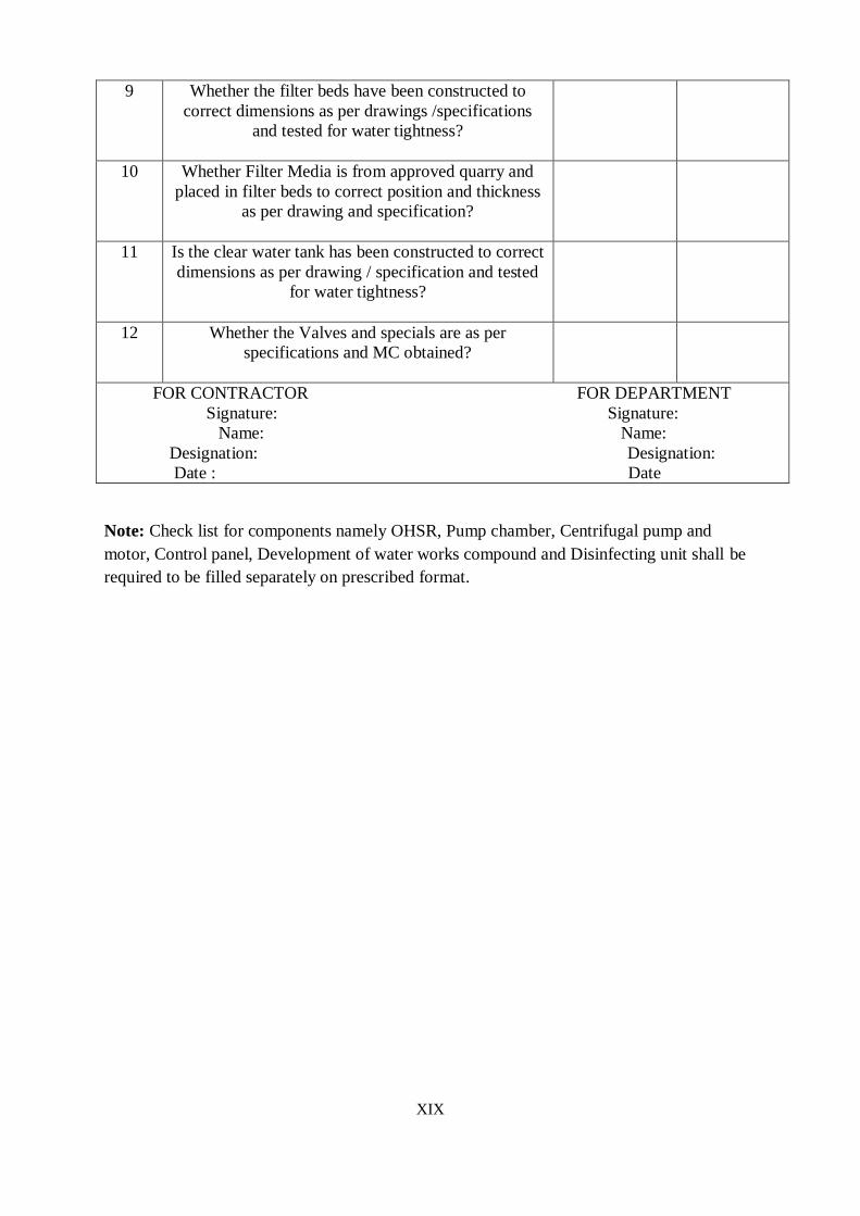
XIX
9 Whether the filter beds have been constructed to
correct dimensions as per drawings /specifications
and tested for water tightness?
10 Whether Filter Media is from approved quarry and
placed in filter beds to correct position and thickness
as per drawing and specification?
11 Is the clear water tank has been constructed to correct
dimensions as per drawing / specification and tested
for water tightness?
12 Whether the Valves and specials are as per
specifications and MC obtained?
FOR CONTRACTOR FOR DEPARTMENT
Signature: Signature:
Name: Name:
Designation: Designation:
Date : Date
Note: Check list for components namely OHSR, Pump chamber, Centrifugal pump and
motor, Control panel, Development of water works compound and Disinfecting unit shall be
required to be filled separately on prescribed format.
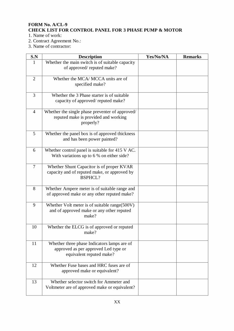
XX
FORM No. A/CL-9
CHECK LIST FOR CONTROL PANEL FOR 3 PHASE PUMP & MOTOR 1. Name of work:
2. Contract Agreement No.:
3. Name of contractor:
S.N Description Yes/No/NA Remarks
1 Whether the main switch is of suitable capacity
of approved/ reputed make?
2 Whether the MCA/ MCCA units are of
specified make?
3 Whether the 3 Phase starter is of suitable
capacity of approved/ reputed make?
4 Whether the single phase preventer of approved/
reputed make is provided and working
properly?
5 Whether the panel box is of approved thickness
and has been power painted?
6 Whether control panel is suitable for 415 V AC.
With variations up to 6 % on either side?
7 Whether Shunt Capacitor is of proper KVAR
capacity and of reputed make, or approved by
BSPHCL?
8 Whether Ampere meter is of suitable range and
of approved make or any other reputed make?
9 Whether Volt meter is of suitable range(500V)
and of approved make or any other reputed
make?
10 Whether the ELCG is of approved or reputed
make?
11 Whether three phase Indicators lamps are of
approved as per approved Led type or
equivalent reputed make?
12 Whether Fuse bases and HRC fuses are of
approved make or equivalent?
13 Whether selector switch for Ammeter and
Voltmeter are of approved make or equivalent?

XXI
14 CT for Ammeter are of approved make or
equivalent?
15 Contractors relays and timers are of approved
make or equivalent?
16 Switch fuse unit is of approved make or
equivalent?
17 Wires are of approved make or equivalent?
18 Whether MC has been obtained and DT
inspection conducted?
19 Whether the control panel has been fitted
properly?
FOR CONTRACTOR FOR DEPARTMENT
Signature: Signature:
Name: Name:
Designation: Designation:
Date : Date

XXII
FORM No. A/CL-10
CHECK LIST FOR SUBMERSIBLE/VT/ CENTRIFUGAL PUMP, MOTOR &
FITTINGS OF DELIVERY PIPE IN PUMP CHAMAER
1. Name of work:
2. Contract Agreement No.:
3. Name of contractor:
S.N Description Yes/No/NA Remarks
1 Whether the pumping set is of reputed make
as per technical specifications, MC obtained
and DT inspection conducted?
2 Whether the shaft, impeller and bearing are as
per technical specifications?
3 Whether the speed of motor is as per
specifications?
4 Whether the actual discharge of pump is as per
specifications?
5 Whether the alignment of the shaft is correct?
6 Whether the alignment of the shaft is correct?
7 Whether combined efficiency of pump set is
as per specifications?
8 Whether head and discharge are correct as per
specifications?
9 Whether foundation and base plate are as per
specifications and foundation bolt are of
proper size and length?
10 Whether the pump set has been power
painted?
11 Whether the suction lift is with in the limit
(4.5 m IS: 9694 Part-I)?
12 Whether the suction pipe joints are airtight
and pump starts without priming?
13 Whether Sluice valve, reflux valve and Air
valve are ISI marked and as per specifications
& the MC has been obtained?
14 Whether the pipes and specials, rubber
packing, nut and bolts are as per
specifications?

XXIII
15 Is there any leakage from fittings?
a) Inside the pump chamber
A) Outside the pump chamber
16 Is Air Valve/Non Return Valve installed
properly?
17 Is proper earthing done for machinery and is
in order?
18 Is there any excess vibrations observed on
running of pump?
19 Is there any overheating of bearings?
20 If the velocity in suction and delivery pipe is
within the limit (Less than 1.5m, not exceed
2m)?
FOR CONTRACTOR FOR DEPARTMENT
Signature: Signature:
Name: Name:
Designation: Designation:
Date : Date
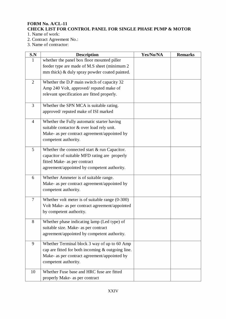
XXIV
FORM No. A/CL-11
CHECK LIST FOR CONTROL PANEL FOR SINGLE PHASE PUMP & MOTOR 1. Name of work:
2. Contract Agreement No.:
3. Name of contractor:
S.N Description Yes/No/NA Remarks
1 whether the panel box floor mounted piller
feeder type are made of M.S sheet (minimum 2
mm thick) & duly spray powder coated painted.
2 Whether the D.P main switch of capacity 32
Amp 240 Volt, approved/ reputed make of
relevant specification are fitted properly.
3 Whether the SPN MCA is suitable rating.
approved/ reputed make of ISI marked
4 Whether the Fully automatic starter having
suitable contactor & over load rely unit.
Make- as per contract agreement/appointed by
competent authority.
5 Whether the connected start & run Capacitor.
capacitor of suitable MFD rating are properly
fitted Make- as per contract
agreement/appointed by competent authority.
6 Whether Ammeter is of suitable range.
Make- as per contract agreement/appointed by
competent authority.
7 Whether volt meter is of suitable range (0-300)
Volt Make- as per contract agreement/appointed
by competent authority.
8 Whether phase indicating lamp (Led type) of
suitable size. Make- as per contract
agreement/appointed by competent authority.
9 Whether Terminal block 3 way of up to 60 Amp
cap are fitted for both incoming & outgoing line.
Make- as per contract agreement/appointed by
competent authority.
10 Whether Fuse base and HRC fuse are fitted
properly Make- as per contract
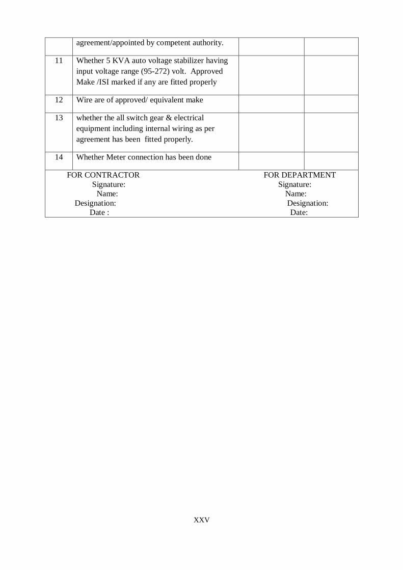
XXV
agreement/appointed by competent authority.
11 Whether 5 KVA auto voltage stabilizer having
input voltage range (95-272) volt. Approved
Make /ISI marked if any are fitted properly
12 Wire are of approved/ equivalent make
13 whether the all switch gear & electrical
equipment including internal wiring as per
agreement has been fitted properly.
14 Whether Meter connection has been done
FOR CONTRACTOR FOR DEPARTMENT
Signature: Signature:
Name: Name:
Designation: Designation:
Date : Date:
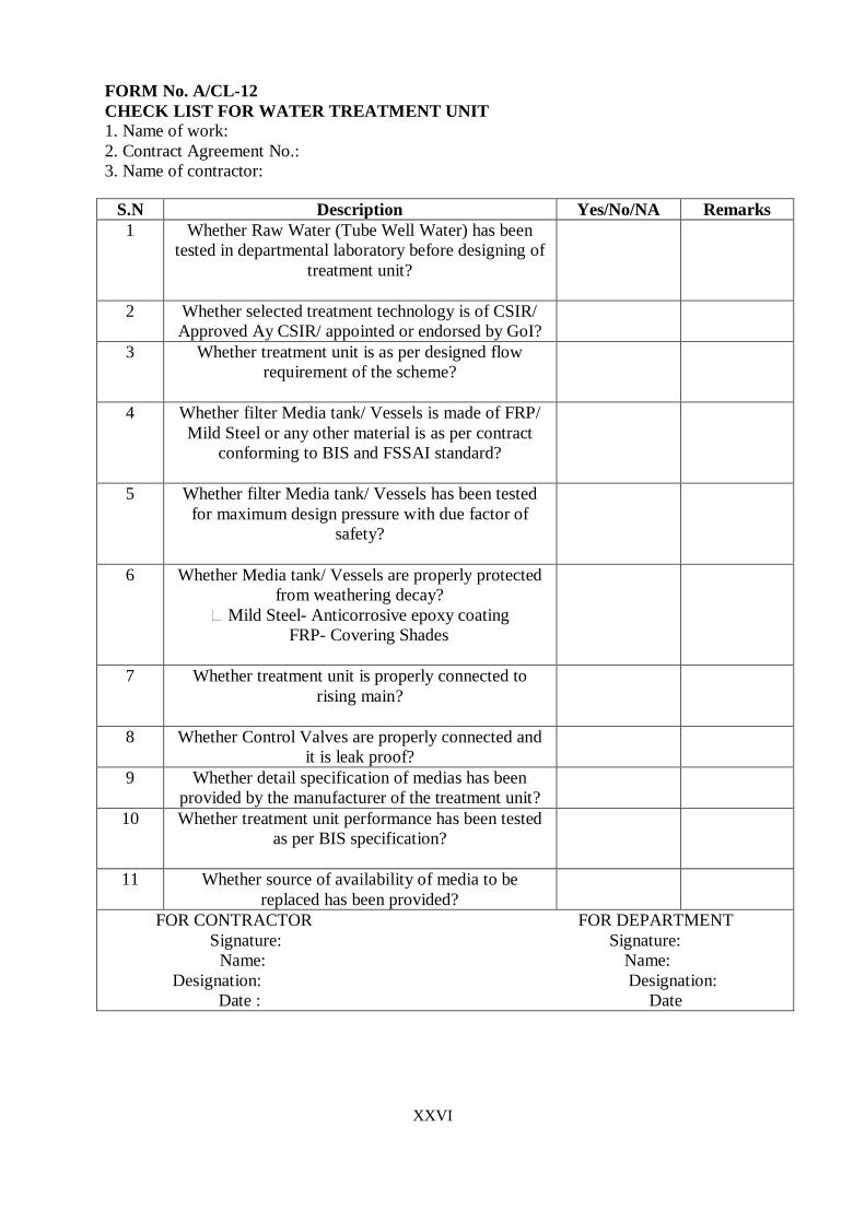
XXVI
FORM No. A/CL-12
CHECK LIST FOR WATER TREATMENT UNIT 1. Name of work:
2. Contract Agreement No.:
3. Name of contractor:
S.N Description Yes/No/NA Remarks
1 Whether Raw Water (Tube Well Water) has been
tested in departmental laboratory before designing of
treatment unit?
2 Whether selected treatment technology is of CSIR/
Approved Ay CSIR/ appointed or endorsed by GoI?
3 Whether treatment unit is as per designed flow
requirement of the scheme?
4 Whether filter Media tank/ Vessels is made of FRP/
Mild Steel or any other material is as per contract
conforming to BIS and FSSAI standard?
5 Whether filter Media tank/ Vessels has been tested
for maximum design pressure with due factor of
safety?
6 Whether Media tank/ Vessels are properly protected
from weathering decay?
Mild Steel- Anticorrosive epoxy coating
FRP- Covering Shades
7 Whether treatment unit is properly connected to
rising main?
8 Whether Control Valves are properly connected and
it is leak proof?
9 Whether detail specification of medias has been
provided by the manufacturer of the treatment unit?
10 Whether treatment unit performance has been tested
as per BIS specification?
11 Whether source of availability of media to be
replaced has been provided?
FOR CONTRACTOR FOR DEPARTMENT
Signature: Signature:
Name: Name:
Designation: Designation:
Date : Date

XXVII
FORM No. A/CL-13
CHECK LIST FOR STEEL STAGING FOR WATER TANKS 1. Name of work:
2. Contract Agreement No.:
3. Name of contractor:
S.N. Description Yes/No/NA Remarks
1 Whether Gusset Plate has been Fixed to foundation bolt?
2 Whether Column Joist/Channel has been fixed to Gusset
Plate?
3 Whether Diagonal Angle/bracing has been fixed to
Gusset Plate?
4 Whether Water tank Platform beam (Joist/Channel) has
been fixed to column?
5 Whether Water tank Platform Sheet has been fixed to
beam?
6 Whether Anti Corrosive painting has been done on
staging structure?
7 Whether section/dimension of structural steel is as per
approved drawing/specification?
FOR CONTRACTOR FOR DEPARTMENT
Signature: Signature:
Name: Name:
Designation: Designation:
Date : Date

XXVIII
FORM No. A/CL-14
CHECK LIST FOR ROTATIONAL MOULDED POLYETHYLENE WATER
STORAGE TANKS
1. Name of work:
2. Contract Agreement No.:
3. Name of contractor:
S.N Description Yes/No/NA Remarks
1 Whether Cylindrical Vertical Tanks placing of staging
has been done?
2 Whether Inlet and overflow with bulkhead / Uniseal
Holding Tank Slip has been fitted of suitable dia.?
3 Whether Outlet and Drain with bulkhead / Uniseal
Holding Tank Slip has been fitted of suitable dia.?
4 Whether is tank is ISI marked ?
FOR CONTRACTOR FOR DEPARTMENT
Signature: Signature:
Name: Name:
Designation: Designation:
Date : Date

XXIX
FORM No. A/CL-15
QUALITY CERTIFICATION 1. Name of work:
2. Contract Agreement No.:
3. Name of contractor:
4. Name of Structure/Location:
Note: This Quality Certificate shall be completed and attached to each Interim Payment
before payment is made.
QUALITY CERTIFICATE This is to certify that we have inspected the conduct of the works in accordance with established
Quality Control procedures and that the items included in this Interim Payment Certificate
satisfy the required quality of works and are acceptable with regard to the specifications and
standards as prescribed under the Contract. Requisite Test Certificates are attached.
Enclosures
1
2
3
4
5
6
7
8
9
10
Signature/Date
Date: ---------------------- J.E A.E. E.E.

XXX
APPENDIX – B
SITE DOCUMENT

XXXI

I
APPENDIX – B
SITE DOCUMENT
Sl. No. Name of Document Responsibility
B/QRF-1 Site Order book Contractor
B/QRF-2 Material Register Contractor
B/QRF-3 Daily Progress Report. Contractor
B/QRF-4 Concrete pour Record Contractor
B/QRF-5 Test Record Contractor
B/QRF-6 Design and Drawing Record Contractor
B/QRF-7
Non Conforming Item Record
PIU

II
Form No B/
QRF-1
SITE ORDER BOOK
Date :
Name of work :
Place/Site :
Agreement No :
Name of Contractor :
Description
COMMENTS ON THE PROGRESS AND QUALITY
Whether Sufficient Labour on Site:
Whether Sufficient Equipment on Site:
Overall Quality of Materials:
Overall Quality of Workmanship:
Instruction To The Contractor

III
[Contractor] Inspection Engineer/with
Designation
Compliance
Site Incharge/J.E.
*(3 copies per set- one copy each to be sent to PIU by the contractor, one copy to be retained at site)
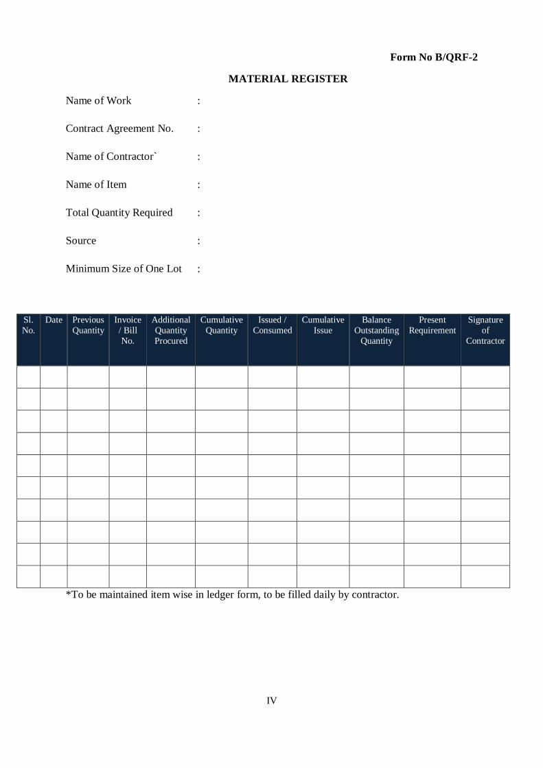
IV
Form No B/QRF-2
MATERIAL REGISTER
Name of Work :
Contract Agreement No. :
Name of Contractor` :
Name of Item :
Total Quantity Required :
Source :
Minimum Size of One Lot :
Sl.
No.
Date Previous
Quantity
Invoice
/ Bill
No.
Additional
Quantity
Procured
Cumulative
Quantity
Issued /
Consumed
Cumulative
Issue
Balance
Outstanding
Quantity
Present
Requirement
Signature
of
Contractor
*To be maintained item wise in ledger form, to be filled daily by contractor.

V
Form No B/QRF-
3
DAILY PROGRESS REPORT
Name of Work :
Contract Agreement No. :
Name of Contractor :
Date :
EQUIPMENT AT SITE
Available :
Under Repair :
Sl.
No.
Name of
Component
Item
Executed
Quantity Location Labour Engaged
Skilled Non
Skilled
Fitter Mason Others
1
2
3
Any Special Difficulties/ happening:
Signature : Signature :
Name : Name :
Date : Date :
For Contractor For Department

VI
Form No B/QRF-
4
CONCRETE POUR RECORD
Name of Work :
Contract Agreement No. :
Name of Contractor :
Steel checked by :
Form work Checked by :
Scaffolding checked by :
Slump checked by :
Cube filled in the presence of :
Date Name of
Component
Structural
Member
Mix
Proportion
Approved
By
Time
of
Start
Qty
Laid
Cement
Bags
Used
Time of
Completion
Concreting done in the presence of:
Signature : Signature :
Name : Name :
Designation Designation :
For Contractor For Department

VII
Form No B/QRF-
5
TEST RECORD
Name of Work :
Contract Agreement No. :
Name of Contractor :
Sl.
No.
Description
of Sample
Date of
Sampling
Size of
Sample
Name of
Laboratory
Status of
D T
Inspection
Status of
Manufacturing
Certificate
Date
and
Result
of
Test
Sign of
Contractor
Sign
of PIU
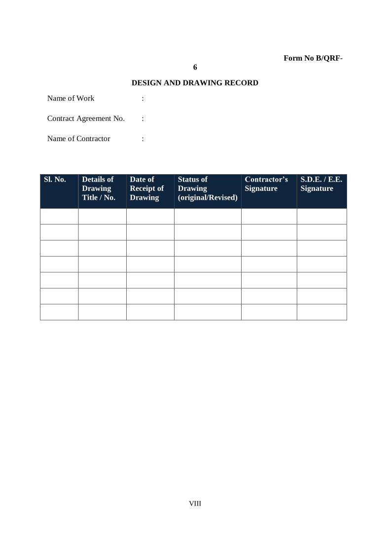
VIII
Form No B/QRF-
6
DESIGN AND DRAWING RECORD
Name of Work :
Contract Agreement No. :
Name of Contractor :
Sl. No. Details of
Drawing
Title / No.
Date of
Receipt of
Drawing
Status of
Drawing
(original/Revised)
Contractor’s
Signature
S.D.E. / E.E.
Signature

IX
Form No B/QRF-
7
NON CONFORMING ITEM RECORD
Name of Work :
Contract Agreement No. :
Name of Contractor :
Brief details of item :
Name and designation of the Authority deciding the non conformation :
Name ……………………………... Designation……………………………...
Reason for nonconforming
Nature of non conforming-
Comments: Yes No
i) Whether the item is structurally sound.
ii) Whether the item is acceptable with in
Specified tolerance limits at reduced rates.
iii) Whether the item requires demolition and re- execution.
Signature : Signature :
Name : Name :
Date : Date :
For Contractor For Contractor

X
APPENDIX-C
QUALITY FIELD
INSPECTION
REPORT

XI
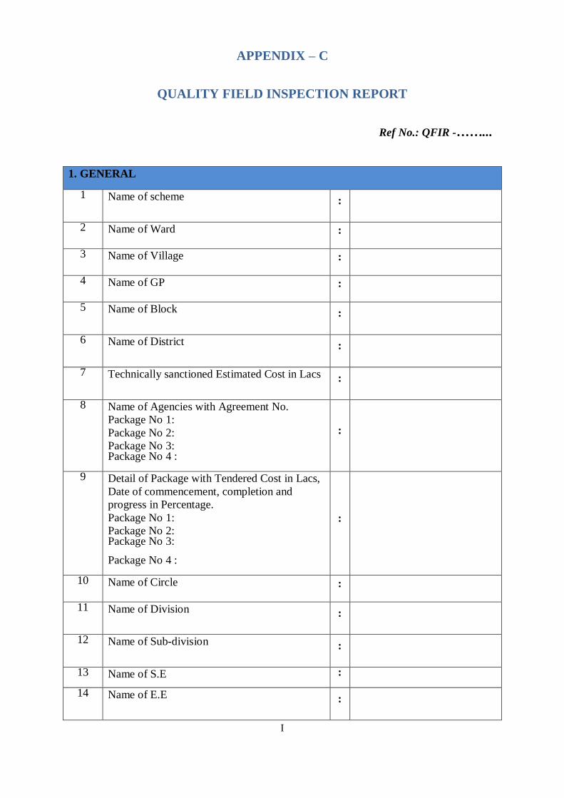
I
APPENDIX – C
QUALITY FIELD INSPECTION REPORT
Ref No.: QFIR -……...
1. GENERAL
1 Name of scheme
:
2 Name of Ward
:
3 Name of Village
:
4 Name of GP
:
5 Name of Block
:
6 Name of District
:
7 Technically sanctioned Estimated Cost in Lacs
:
8 Name of Agencies with Agreement No.
Package No 1:
Package No 2:
Package No 3: Package No 4 :
:
9 Detail of Package with Tendered Cost in Lacs,
Date of commencement, completion and
progress in Percentage.
Package No 1:
Package No 2: Package No 3:
Package No 4 :
:
10 Name of Circle
:
11 Name of Division
:
12 Name of Sub-division
:
13 Name of S.E :
14 Name of E.E
:

II
15 Name of A.E
:
16 Name of J.E
:
17 Name of Chairman of GPWSC
:
18 Scheme Inspected by C.E with date/ reference
:
19 Scheme Inspected by S.E with date/ reference
:
20 Scheme Inspected by E.E with date/ reference
:
21 Scheme Inspected by E.E (QMSW) with date/
reference
:
2. DETAILED INFORMATION ABOUT VILLAGES:
Sl. No.
Name of
Village
Present
Population
No. of Households
No. of Pvt.
Water
Connections
No. of Stand
Posts
1
2
3

III
3. QUALITY CONTROL DOCUMENTS AND TESTING DETAILS
1 Documents available at site as per list 1
:
2 Whether the agreement with specification and copy of
sanctioned estimate available at site?
:
3 Whether the Approved structural drawing available at
site?
:
4 Field laboratory equipments available at site as per list 2
:
5 Material being tested at site and lab by contractor as per
list 3.
:
6 Availability of field equipments as per list 4.
:
7 Items for which manufacturing certificate obtained as per
List 5
:
8 Items for which Inspection by departmental team has
been done as per List 6.
:
9 Check list of works filled up as per list 7.
:
10 Testing of finished work carried out as per list 8.
:
11 Penalties imposed on account of Non-conformance of
work as per list 9.
:
12 Overall Quality Control of works as per list 10.
:
13 Samples taken for testing during field inspection by
consultant as per list 11.
:
14 Number of tests conducted in the field as per list 12.
:
15 Field book /Engineer diary maintained by JE
:

IV
List - 1: SITE DOCUMENT
Sl. No
Description
Availability at site Yes / No/ NR
Remarks
1 Site Order book
2 Material Register
3 Daily Progress Report.
4 Concrete pour Record
5 Test Record
6 Design andDrawing Record
7 Non Conforming Item
Record

V

VI
List - 2: FIELD LABORATORY EQUIPMENT AVAILABLE AT SITE
Sl. No
Description
Availability at site Yes / No/NR
Remarks
1 Compression testing machine
2 Sieve set complete
3 Measuring jars
4 Screw gauge
5 Vernier calliper
6 Balance
7 Slump cone
8 Cube mould 2 sets.
9 Hydraulic testing machine
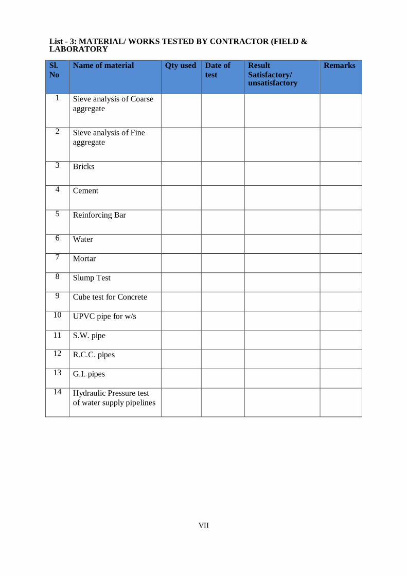
VII
List - 3: MATERIAL/ WORKS TESTED BY CONTRACTOR (FIELD & LABORATORY
Sl.
No
Name of material
Qty used
Date of
test
Result
Satisfactory/ unsatisfactory
Remarks
1 Sieve analysis of Coarse
aggregate
2 Sieve analysis of Fine
aggregate
3 Bricks
4 Cement
5 Reinforcing Bar
6 Water
7 Mortar
8 Slump Test
9 Cube test for Concrete
10 UPVC pipe for w/s
11 S.W. pipe
12 R.C.C. pipes
13 G.I. pipes
14 Hydraulic Pressure test
of water supply pipelines

VIII
List-4: EQUIPMENTS/ T&P AVAILABLE AT SITE
Sl.
No.
Equipment
Availability Yes / No/NR
Remarks
1 Mixture Machine with stand by arrangement
2 Vibrator with stand by arrangement
3 Lifting pump for curing
4 Levelling instrument
5 Hoisting lift

IX
List-5: DETAILS OF MANUFACTURER CERTIFICATES
Sl.
No.
Description
Qty. used
MC
availability Yes / No/ NR
Acceptability By PIU
Remarks
1 Cement
2 Steel for
Reinforcement and
structural steel
3 Pipe such as GI ,
PVC ,MS, CI, DI,
SW ,RCC etc.
4 AC/GI/Fiber glass
sheets
5 Electrical
cables/fans and
fixtures
6 Switches/sockets
and boards
7 Flow measuring
devices
8 Control Panel
9 Lightening arrestor
10 Water Level
indicator and
controllers.
11 Disinfection Units
12 Pump and Motor
13 All type of specials
such as PVC, GI, CI
etc.
14 All types of valves
such as sluice valve,
Air valve etc.
15 Any other item as
per agreement
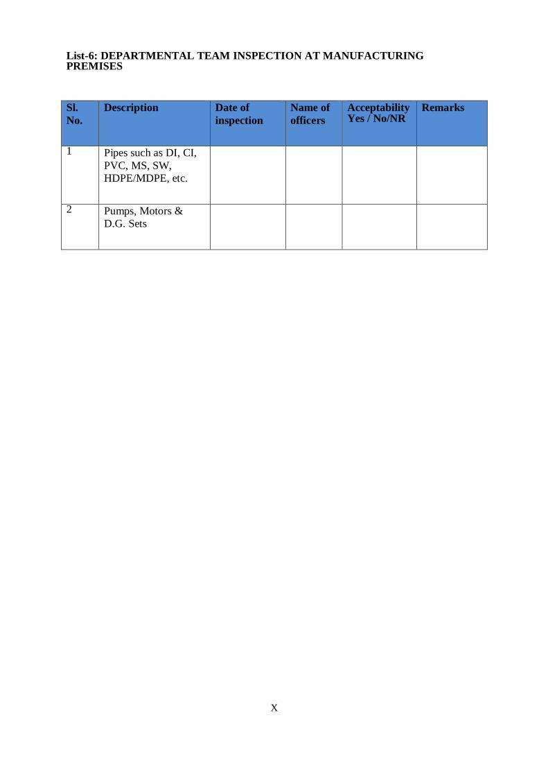
X
List-6: DEPARTMENTAL TEAM INSPECTION AT MANUFACTURING PREMISES
Sl.
No.
Description
Date of
inspection
Name of
officers
Acceptability Yes / No/NR
Remarks
1 Pipes such as DI, CI,
PVC, MS, SW,
HDPE/MDPE, etc.
2 Pumps, Motors &
D.G. Sets

XI
List-7: CHECK LIST OF WORKS
Sl.
No.
Description
Field Status
Details of
rejection
Remarks
1 Tube well
2 Laying and jointing of pipe
line, back filling, hydro testing
3 Pumping machinery & fittings
of delivery pipe in pump
chamber (Tubewell based
scheme)
4 Disinfecting plant
5 Pump chamber
6 Development of water works
7 O.H.S.R
8 Water treatment plant
9 Control panel for 3 phase
pump & motor.
10 Centrifugal pump, motor &
fittings of delivery pipe in
pump chamber
11 Quality certificate

XII
List-8: TESTING OF FINISHED WORKS
Sl.
No.
Item of work Qty.
Test
Date of
test
Results Check
level
Remarks
1 Excavation
2 Refilling of
trenches
3 Road
reinstatement
4 DCP
5 Thickness of cc
floor
6 Mortar for
masonry
7 Plaster
8 PCC
9 R.C.C
10 Chaukhats
11 Windows
12 Fittings
13 Distemper
14 Painting
15 Glass panes
16 Wooden doors
17 Water tightness of
roofs
18 Test for yield of
Tube Well
19 Efficiency of
WTP
i)Hydraulic
ii)TDS
iii)Total hardness
iv)MPN
20 Water tightness of
structures
i)OHSR
ii)UGSR
iii)Units of WTP

XIII
List-9: PENALITIES ON A/C OF NONCONFORMANCE OF WORK
Sl. No.
Name of
work/Material
Test
Results
Qty. of
material
rejected
Amount
of
Penality
if
accepted
Remark
Actual
Standard
1
2
3
4

XIV
List-10: OVERALL QUALITY OF CONSTRUCTION FOR DIFFERENT ITEMS OF WORKS
Sl.
No.
Item of works
Quality of construction
Remarks
Satisfactory
Unsatisfactory
(RI)
1 Tube well
2 Pump chamber
3 OHSR
4 UGSR
5 Water works
development
6 Distribution
system
7 Pump set of
TW
Water
treatment plant
8 Electrical
works at
treatment plant
9 Treatment Unit
10 Item of work
requiring
special
attention for
quality
improvement

XV
List-11: SAMPLE TAKEN FOR TESTING DURING FIELD VISIT
S.No. Name of Item Work
where used
Qty. Sealed Name of Div.
where delivered
for testing
Remarks
1
2
3
4
Note: For the samples taken for testing during the field visit, the results are to be reviewed and a copy of the same should be sent to QMSW/Consultant within 15 days.

XVI
LIST-12: TEST CONDUCTED BY INSPECTION TEAM
S.
No.
Name of
Item
Locat
ion
Type of test Test
Result
Standards % Passing Re
ma
rks
1 Coarse Aggregate
20mm
10 mm
Sieve analysis
A/TR-2
Sieve 20 10
40 100 -
20 85- 100 -
12.5 - 100
10 0- 20 85- 100
4.75 0-5 0-20
2.36 - 0-5
2 Fine aggregate
Concrete Zone
II
Plaster
IS:1542
Masonry IS:2116
Sieve
analysis
Silt content
Sieve
analysis
Silt content
Sieve
analysis
Silt content
A/TR-3
A/TR-
12
A/TR-3
A/TR-
12
A/TR-3
A/TR-12
8% Max.
8% Max.
8% Max.
3 Steel IS:1786
8 mm
10 mm
12 mm
16 mm
20 mm
25 mm
Dia.
Wt. / M in
Kg
Dia.
Wt. / M in
Kg
Dia.
Wt. / M in
Kg
Dia.
Wt. / M in
Kg
Dia.
Wt. / M in
Kg
0.395±7%
0.617±7%
0.888±5%
1.58±5%
2.47±3%

XVII
Dia.
Wt. /M in Kg
3.85±3%
4 UPVC pipe
w/s
Class – 3
Size - 90 mm
Size 110 mm
OD
Min.
Max.
Wall
Thickness
Make
OD
Min.
Max.
Wall
Thickness Make
90 mm
88.9
91.1
3.1 to 3.7 mm
110 mm
108.6
111.4
3.7 to 4.3 mm
5 SW Pipe
Class – SP-1
Size - 100 mm
Size 150 mm
ID
Thickness
Internal depth
of socket
Excess
shoulder
Length of
Grooving
ID
Thickness
Internal depth
of socket
Excess
shoulder
Length of Grooving
100 mm
12 mm
50 mm
10 mm
75 mm
150 mm
15 mm
57 mm
11 mm
85.5 mm
6 Bricks (20) Color
Length(mm)
Cherry red
4600±80 mm

XVIII
Width
Height
Comp.strength
2200±40
1400±40 7.5 N/mm2
7 Barbed wire
A-1
Gause(mm)
Mass (gm/m)
2.5±0.04 155 to 136
8 M.S Pipe
NB
Thickness NB
Thickness
150 mm
5.4 mm 200 mm
8.0 mm
9 SS Screen in
mm
NB
Thickness
NB
Thickness
150 mm
5.0 mm upto 200 M
6.3 mm upto 350 M
200 mm
6.3 mm upto 200 M
8.00 mm upto 350 M
10 Floor Thickness
40 mm P.C.C
11 Plaster
Thickness
12.5 mm
12 Door
Thickness
40 mm
13 Roof slab
Thickness
150 mm
14 M.S Girder
Size
250 mmx125 mm
15 Angle iron
Pickets
Size
Thickness
40x40x6 mm
6 mm
16 LDPE Sheet
Thickness
200 micron
17 Cube test
M15
M20
M25
Compressive
strength
Compressive
strength
Compressive
strength
15 N/mm2
20 N/mm2
25 N/mm2
18 Slump test Slump in mm
40-70 mm
19 Cement
Grade
Date of
Manufacture.
Fineness
43
Not more than 10%
Residue
Signature of Inspecting officer

XIX
APPENDIX-D
TEST REPORT
FORMATS

XX

I
APPENDIX – D
TEST REPORT FORMATS
Sl. No. Test Report Title Reference IS Code Form No.
1 Test Certificate for Cement 1489 - 1991
8112 -1989
D/TR -1
2 Test Certificate for Coarse Aggregate 383- 1970
2386 - 1963
D/TR -2
3 Test Certificate for fine Aggregate 383 - 1970
2386- 1963
D /TR -3
4 Test Certificate for water 3205 - 1987 D/TR -4
5 Compressive Strength of Concrete 456 - 2000
516 - 1959
D/TR -5
6 Concrete Slump Test 1199 -1959 D/TR -6
7 Hydrostatic Test for NP Pipes Manual D/TR -7
8 Hydrostatic Test for pressure Pipes Manual D/TR -8
9 Leak Test for Under Ground RCC
Structures
3370 - 2009 D/TR -9
10 Leak Test for Elevated RCC
Structures
3370 -2009 D/TR -10
11 Water absorption of bricks 3495 – 1992 D/TR -11
12 Silt content of fine aggregate 383(III) – 1963 D/TR -12

II
Ref No. …………………………………...Dated ………………. Form No D/TR-1
TEST CERTIFICATE FOR CEMENT
Name of work :
Contract Agreement No :
Name of contractor :
Source of supply ;
Date of sampling & Quantity :
Material description :
CONSISTENCY
Trial No. Weight of
cement
Weight of
water
Percentage
of water
Reading
of
indicator
Consistency
(P)
Remarks
SETTING TIME
Setting Time Time recorded
when water
added
Time recorded
at set
Setting time Remarks
Initial
Final
FINENESS
Weight of cement
used
Retained on 0.075
Sieve
Percentage retained Remarks
COMPRESSIVE STRENGTH
emperature Date of
casting
Date of
testing
Age of
specimen
Crushing
load (T)
Crushing
strength
kg/cm2
Remark
Signature: Signature:
Name: Name:
Date: Date:
For Contractor For Department

III
Ref No. ………………………………...Dated ……………… Form No D/ TR-2
TEST CERTIFICATE FOR COARSE AGGREGATE
Name of work :
Contract Agreement No :
Name of contractor :
Source of supply :
Date of sampling & Quantity :
Material description :
A - 20 mm Nominal size
Sieve size
in mm
Weight
retained
(g)
Cumulative
weight
retained
Cumulative
% retained
Cumulative
% passing
Remarks/Standards
% Passing
40 mm 100
20 mm 85-100
10 mm 0-20
4.75 mm 0-5
Pan
TOTAL
B - 10 mm Nominal size
Sieve size
in mm
Weight
retained
(g)
Cumulative
weight
retained
Cumulative
% retained
Cumulative
% passing
Remarks/Standards
% Passing
12.5 mm
100
10 mm
85-100
4.75 mm
0-20
2.36 mm
0-5
Pan
TOTAL
(C+500)
Fineness modulus of coarse aggregate = 100 C is cumulative % retained
Signature: Signature:
Name: Name:
Date: Date:
For Contractor For Department
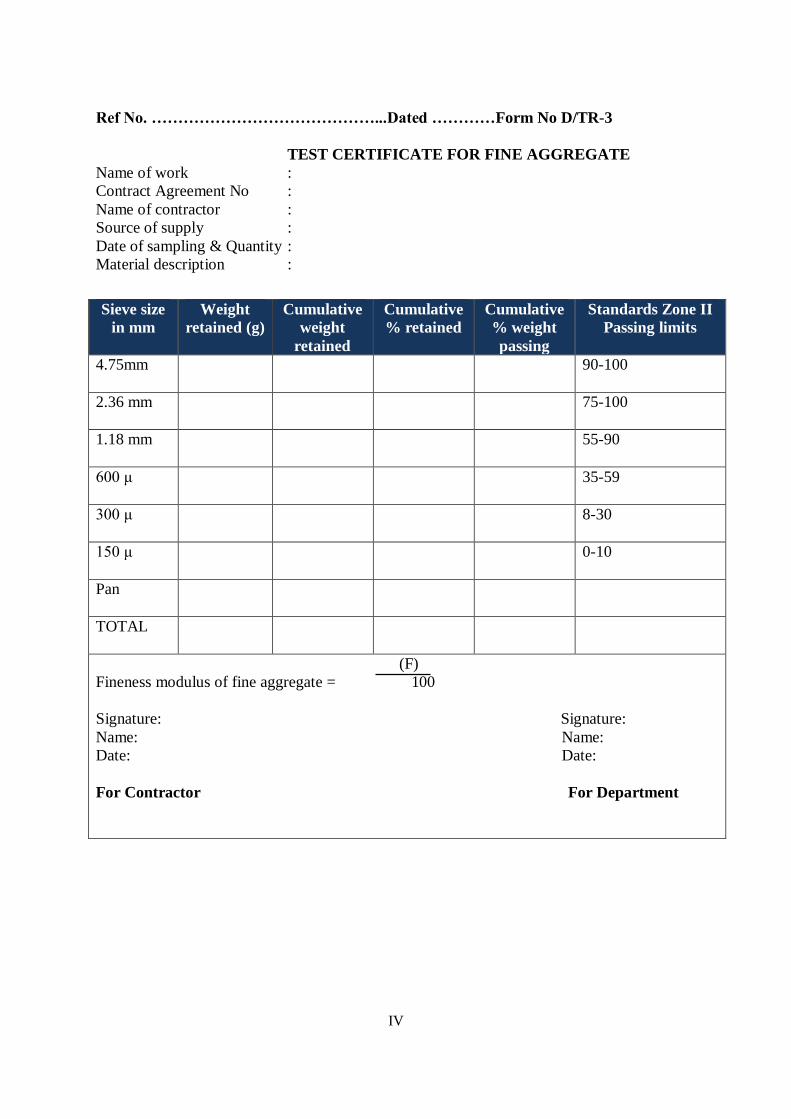
IV
Ref No. ……………………………………...Dated …………Form No D/TR-3
TEST CERTIFICATE FOR FINE AGGREGATE
Name of work :
Contract Agreement No :
Name of contractor :
Source of supply :
Date of sampling & Quantity :
Material description :
Sieve size
in mm
Weight
retained (g)
Cumulative
weight
retained
Cumulative
% retained
Cumulative
% weight
passing
Standards Zone II
Passing limits
4.75mm
90-100
2.36 mm
75-100
1.18 mm
55-90
600 μ
35-59
300 μ
8-30
150 μ
0-10
Pan
TOTAL
(F)
Fineness modulus of fine aggregate = 100
Signature: Signature:
Name: Name:
Date: Date:
For Contractor For Department

V
Ref No. ………………………………...Dated ………………Form No. D/TR-4
TEST CERTIFICATE FOR WATER (For saline zone only)
Name of work :
Contract Agreement No. :
Name of contractor :
Source of supply :
Date of sampling & Quantity :
Material description :
Sl.
No.
Color PH
value
Organic
Solids
(mg/l)
Inorganic
Solids
(mg/l)
Sulphates
(mg/l)
Chlorides
(mg/l)
Suspended
matter(mg/l)
Limits
> 6 < 2000 < 3000 < 500 PCC <2000
RCC <
1000
< 2000
1
2
3
Remarks / Recommendations
………………………………………………………………………………...
Signature: Signature:
Name: Name:
Date: Date:
For Contractor For Department
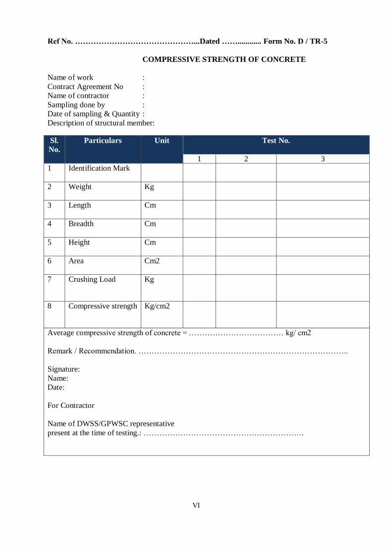
VI
Ref No. ………………………………………...Dated ……............ Form No. D / TR-5
COMPRESSIVE STRENGTH OF CONCRETE
Name of work :
Contract Agreement No :
Name of contractor :
Sampling done by :
Date of sampling & Quantity :
Description of structural member:
Sl.
No.
Particulars Unit Test No.
1 2 3
1 Identification Mark
2 Weight
Kg
3 Length
Cm
4 Breadth
Cm
5 Height
Cm
6 Area
Cm2
7 Crushing Load
Kg
8 Compressive strength
Kg/cm2
Average compressive strength of concrete = ……………………………… kg/ cm2
Remark / Recommendation. ……………………………………………………………………..
Signature:
Name:
Date:
For Contractor
Name of DWSS/GPWSC representative
present at the time of testing.: …………………………………………………….
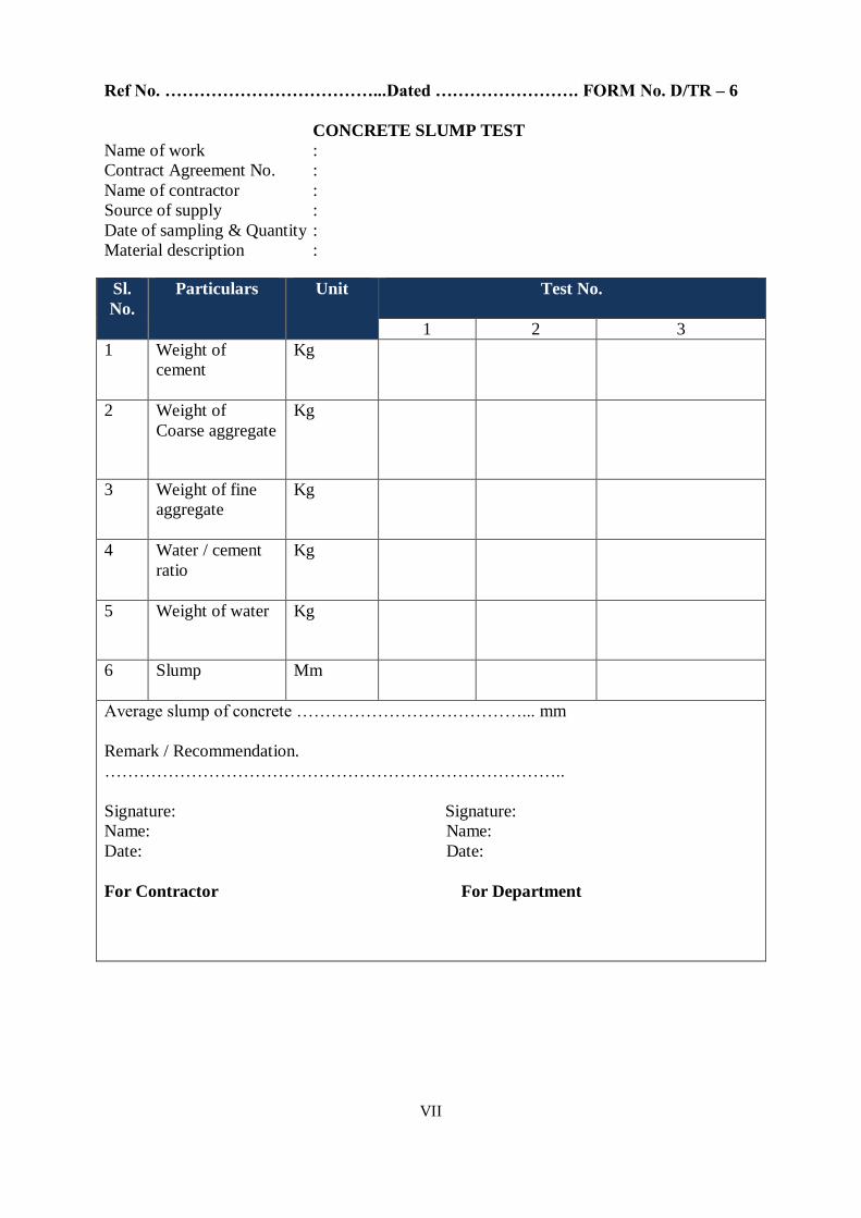
VII
Ref No. ………………………………...Dated ……………………. FORM No. D/TR – 6
CONCRETE SLUMP TEST
Name of work :
Contract Agreement No. :
Name of contractor :
Source of supply :
Date of sampling & Quantity :
Material description :
Sl.
No.
Particulars Unit Test No.
1 2 3
1 Weight of
cement
Kg
2 Weight of
Coarse aggregate
Kg
3 Weight of fine
aggregate
Kg
4 Water / cement
ratio
Kg
5 Weight of water
Kg
6 Slump
Mm
Average slump of concrete …………………………………... mm
Remark / Recommendation.
……………………………………………………………………..
Signature: Signature:
Name: Name:
Date: Date:
For Contractor For Department

VIII
Ref No. …………………………………………...Dated ………………Form No. D/ TR – 7
HYDROSTATIC TEST FOR NP PIPES
Name of work :
Contract Agreement No. :
Name of contractor :
Source of supply :
Material description :
Sl. No. Internal
diameter
(mm)
Time
in
hours
Stretch Length
(m)
Water level drop
(mm)
Volume of water to
restore to original
level (liters)
10
min
30 min 10 min 30 min
Remark / Recommendation. ……………………………………………………………………..
Signature: Signature:
Name: Name:
Date: Date:
For Contractor For Department

IX
Ref No. ……………………………………...Dated ……………………. Form No. D/TR –
8
HYDROSTATIC TEST FOR PRESSURE PIPES
Name of work :
Contract Agreement No. :
Name of contractor :
Source of supply :
Material description :
Sl.
No.
Material
of pipe
Internal
diameter
(mm)
Stretch Length
(m)
Applied
test
pressure
(kg/cm2
Time (hours)
Observations
1 2 3
Remark / Recommendation.
……………………………………………………………………..
Signature: Signature:
Name: Name:
Date: Date:
For Contractor For Department

X
Ref No. ……………………………………. Dated ……………………. Form No. D/TR – 9
LEAK TEST FOR UNDER GROUND RCC STRUCTURES
Name of work :
Contract Agreement No. :
Name of contractor :
Material description :
Date of Filling
Initial Water level
Observation
no.
Date of
observation
Water level
(m)
Drop (mm) Remark
1
2
3
4
5
6
7
Remark / Recommendation.
……………………………………………………………………..
Signature: Signature:
Name: Name:
Date: Date:
For Contractor For Department

XI

XII
Ref No. …………………………………………. Dated ………………Form No. D/TR – 10
LEAK TEST FOR ELEVATED RCC STRUCTURES
Name of work :
Contract Agreement No. :
Name of contractor :
Description :
Date of Filling
Water Level
Observation
no.
Date of observation Initial Final Time
1.
2.
3.
4.
5.
6.
Remark / Recommendation.
……………………………………………………………………..
Signature: Signature:
Name: Name:
Date: Date:
For Contractor For Department
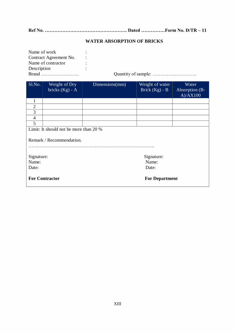
XIII
Ref No. ……………………………………………. Dated ……………Form No. D/TR – 11
WATER ABSORPTION OF BRICKS
Name of work :
Contract Agreement No. :
Name of contractor :
Description :
Brand …………………… Quantity of sample: ……………………….
Sl.No. Weight of Dry
bricks (Kg) - A
Dimensions(mm) Weight of water
Brick (Kg) - B
Water
Absorption (B-
A)/AX100
1
2
3
4
5
Limit: It should not be more than 20 %
Remark / Recommendation.
……………………………………………………………………..
Signature: Signature:
Name: Name:
Date: Date:
For Contractor For Department
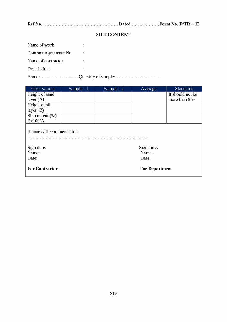
XIV
Ref No. …………………………………………. Dated ………………Form No. D/TR – 12
SILT CONTENT
Name of work :
Contract Agreement No. :
Name of contractor :
Description :
Brand: …………………… Quantity of sample: ……………………….
Observations Sample - 1 Sample - 2 Average Standards
Height of sand
layer (A)
It should not be
more than 8 %
Height of silt
layer (B)
Silt content (%)
Bx100/A
Remark / Recommendation.
……………………………………………………………………..
Signature: Signature:
Name: Name:
Date: Date:
For Contractor For Department

For Detail ContactEngineer-in-Chief-cum-Member SecretaryPublic Health Engineering DepartmentNirman Bhawan, Patna-800015Tel: (0612)-2546348. Whatsapp Number 85444-28865Grievance Redressal Cell Toll Free: 1800-1231-121
9:30 AM ~ 6:00 PM
QUALITY MONITORING
SYSTEM