Quality Improvement Program for the B83 Bomb Hand...
60
SANDIA REPORT SAND97–8012 • UC–706 Unlimited Release Printed April 1998 Quality Improvement Program for the B83 Bomb Hand Truck M. B. Loll, S. A. Buck Prepared by Sandia National Laboratories Albuquerque, New Mexico 87185 and Livermore, California 94550 Sandia is a multiprogram laboratory operated by Sandia Corporation, a Lockheed Martin Company, for the United States Department of Energy under Contract DE-AC04-94AL85000. Approved for public release; distribution is unlimited.
Transcript of Quality Improvement Program for the B83 Bomb Hand...

SANDIA REPORTSAND97–8012 • UC–706Unlimited ReleasePrinted April 1998
Quality Improvement Program for the B83Bomb Hand Truck
M. B. Loll, S. A. Buck
Prepared bySandia National LaboratoriesAlbuquerque, New Mexico 87185 and Livermore, California 94550
Sandia is a multiprogram laboratory operated by Sandia Corporation,a Lockheed Martin Company, for the United States Department ofEnergy under Contract DE-AC04-94AL85000.
Approved for public release; distribution is unlimited.

2

3
SAND97-8012 DistributionUnlimited Release Category UC–706Printed April 1998
Quality Improvement Programfor the B83 Bomb Hand Truck
Marvin B. LollHandling Equipment Engineering Department
Steven A. BuckAdvanced Weapon System Engineering Department
Sandia National LaboratoriesLivermore, California 94551
AbstractThis report describes the problems, issues, and history of the H1347 bomb hand truck for
the B83 bomb after the bomb was put into stockpile in the mid-1980s. Major issues that werereported in Unsatisfactory Reports (URs) were cracking problems on stacking fixture welds,cracked welds on the caster bracket receptacles on the cradle, cracked caster mounting brackets,casters unlocking from the swivel lock position, and caster tires rubbing and binding on thestacking frame. Resolution of these and other problems is described.
The introduction of the H695B storage-only bomb hand truck to alleviate a shortage ofbomb hand trucks in the mid-1990s is described. The development and qualification of theH1347A bomb hand truck as a replacement for the H695B is covered. The results from load testevaluations on the stacking fixture, cradle, and casters for the H1347 are described along withtowing results on one and two-high stack configurations of B83 bombs in bomb hand trucks.New towing and truck/trailer transport procedures are described. Development, evaluation, andproduction recommendations for a stronger caster mounting bracket are described.

4
Contents
Page
Acknowledgments.......................................................................................................................8
Introduction .................................................................................................................................9
Background ...............................................................................................................................12
Bomb Hand Truck Description .................................................................................................13
Summary of the Problems and Concerns on the Bomb Hand Truck Leading to theQuality Improvement Program..................................................................................................18
Summary of Quality Improvement Program Upgrades.............................................................25
Upgrade to H1347 (-03) and H695B (-01) ....................................................................25Manual Changes............................................................................................................25Upgrade to H1347A ......................................................................................................26Other Changes ...............................................................................................................27Possible Future Upgrades..............................................................................................27
Stockpile Upgrade Program to H1347A ...................................................................................27
Bomb Hand Truck Definition and History................................................................................28
H1347 (214073-00/01).................................................................................................28H1347 (214073-02) ......................................................................................................28H1347 (214073-03) ......................................................................................................29H695B (214253-00) .....................................................................................................29H695B (214253-01) .....................................................................................................30H1347A (214255-00) ...................................................................................................30
History of the H1347-Associated Stacking Fixture...................................................................30
Description of the H1347-Associated Stacking Fixture ...............................................30Weld Cracking Problem................................................................................................32Weld Evaluation and Repair Program...........................................................................32
H1347-Associated Stacking Fixture and Bomb Hand Truck Testing Program ........................34
Weld Pull Testing on the H1347-Associated Stacking Fixture.........................34
Additional Weld Pull Testing on the H1347-Associated StackingFixture after Weld Repair..................................................................................34
Forward and Aft Loading of Bomb in H1347 Bomb Hand Truck toSimulate SST “g” Loading Requirement ..........................................................35
Conclusion and Recommendations Regarding the H1347-AssociatedStacking Fixture ............................................................................................................35
History of the H695B-Associated Stacking Fixture..................................................................36
Load Testing..................................................................................................................37
Development of the H1347A-Associated Stacking Fixture ......................................................37
Center Section Design and Test Results .......................................................................38

5
Casting Design and Casting Process .............................................................................39H1347A-Associated Stacking Fixture Testing Program...............................................40
Vibration Tests to Qualify New H1347A-Associated Stacking Fixture ...........40Structural Tests to Qualify New H1347A-Associated Stacking Fixture...........40
Conclusions Regarding the H1347A-Associated Stacking Fixture ..............................41Conclusion Regarding the H1347-Associated Stacking Fixturefor Assembly D .............................................................................................................42
Cradle and Caster Assembly Evaluation ...................................................................................42
Structural Tests to Evaluate Weld Cracks in the H1347 Cradle Receptacle for theCaster Mounting Bracket and Strength of Caster Assembly Mounting Brackets .........42Series of Towing Tests to Evaluate Towing a One-High Stack Configuration ............43Towing Demonstration of a Two-High Stack Configuration........................................43Analysis to Define Shoring Conditions for Truck/Trailer Transport ............................4312-Inch Drop Test of a One-High Stack B83/H1347 at 65o F......................................44Conclusions Regarding the Cradle and Caster Assembly .............................................44
Caster Mounting Bracket Evaluation and Redesign..................................................................44
Cracked Caster Brackets on the B83 Bomb Hand Truck ..............................................44Why the Casters Crack ..................................................................................................45The Options...................................................................................................................46
Option 1: Disallow two-high stacking. ............................................................46
Option 2: Continue current position.................................................................46
Option 3: Redirect the load path. .....................................................................46
Option 4: Redesign and implement stronger caster mounting brackets. ..........46
Other considerations: Use of flat-sided casters. ...........................................................47Redesign, Analysis, and Testing of a Stronger Mounting Bracket ...............................47Implementation Options and Recommendations ..........................................................52
Additional Testing to Support the Quality Improvement Program...........................................53
Tensile Tests on Cracked Stacking Fixture Bolts .........................................................53Structural Evaluation and Qualification of New H1640 Castering Tool ......................54Temperature Testing on Decals.....................................................................................55
Summary and Conclusions........................................................................................................55
References .................................................................................................................................57

6
IllustrationsNo. Page
1. B83 bomb in H1347 bomb hand truck. ...................................................................92. Two-high stack of B83 bombs in H1347 bomb hand truck...................................103. B83 bombs in H695B (upper) and H1347 (lower) bomb hand truck. ...................114. H1347A truck, P/N214255-00...............................................................................125. Fabrication and upgrade flowpath for B83 bomb hand truck. ...............................126. Size and weight of the H1347 bomb hand truck....................................................147. H1347 bomb hand truck, P/N 214073-03..............................................................148. Cradle assembly used for H1347, H695B, and H1347A bomb hand trucks. ........169. H1095 stacking frame, P/N 320464-01. ................................................................16
10. Barrel-type caster assemblies.................................................................................1711. H1640 castering tool engaging wheel hub on flat-sided caster assembly..............1712. Weld cracks on H1347-associated stacking fixture. ..............................................1913. Weld cracks on caster assembly receptacle on cradle............................................1914. Cracks in caster assembly mounting bracket (barrel caster)..................................2015. Condition of bearings, seals, nuts, and dust caps in caster assembly. ...................2016. Longitudinal cracks in stacking fixture bolts.........................................................2117. Typical damage to barrel-type caster from castering tool......................................2218. H1347-associated stacking fixture, P/N 450232-00. .............................................3119. Cross-section of welds on H1347-associated stacking fixture. .............................3320. H1347A-associated stacking fixture......................................................................3721. Prototype of a stronger caster mounting bracket (A357-T6). ................................4822. Cutaway of prototype caster mounting bracket. ....................................................4823. Effect of interference fit between steel sleeve and A356-T6 aluminum
mounting bracket. ..................................................................................................4924. Stress distribution in current mounting bracket (A356-T6 aluminum). ................5025. Stress distribution in stronger mounting bracket (A357-T6 aluminum)................5026. Voids in A356-T6 aluminum casting. ...................................................................5127. Voids in A357-T6 aluminum casting. ...................................................................5228. H1640 castering tool..............................................................................................54

7
TablesNo. Page
1. B83 bomb hand truck hardware definition.................................................................152. H1347 unsatisfactory reports (URs)...........................................................................233. Towing and truck/trailer transport requirements........................................................264. Summary of tensile test results and conditions. .........................................................345. Tensile test results after weld repair...........................................................................346. Summary of stacking fixture development tests for the center section......................387. Aluminum material properties. ..................................................................................51

8
Acknowledgments
Cook Story, Dennis Beyer, and Robert Monson, SNL/CA Managers who strongly supported theB83 H-gear upgrade efforts.
Karl Arnold, AlliedSignal/Federal Manufacturing & Technology (FM&T)/Kansas City Plant forthe H1347A-associated stacking fixture design while he was in residency at SNL/CA fromFebruary to December, 1993.
Lorenzo Asia, 2282, for working out the details of each H1347A-associated stacking fixturedesign concept to determine feasibility.
Darryl Brunswick, formerly AlliedSignal/FM&T and Allen Rahe, AlliedSignal/FM&T, ProductEngineers on the B83 bomb hand truck.
John Stewart, AlliedSignal/FM&T, Product Engineer on the H1347A-associated stacking fixture.
Jeff Greener, formerly AlliedSignal/FM&T, and Bob Owens, AlliedSignal/FM&T, as castingengineers on the H1347A-associated stacking fixture.
Noel Betow, Allied-Signal/FM&T, as the quality engineer and later as the casting engineer on theH1347A-associated stacking fixture.
Larry Brown, 2265, for lead engineering efforts on the H695B bomb hand truck and the design ofthe H1640 caster tool.
Darrla Giersch, 2165, formerly 2265, for engineering efforts on the H1347A-associated stackingfixture.
Steve Buck, 2254, formerly 2265, for all the testing on the B83 bomb hand trucks.
Brian Oden, 2265, and Steve Ehle, 2211, formerly 2265, for quality support on all the B83 bombhand trucks.
Y-R Kan, 8742, and Paul Jin, 8742, for their contributions on structural analysis.
Dennis Nelson, 8812, for his contribution for vibration and shock analysis.

9
Quality Improvement Programfor the B83 Bomb Hand Truck
Introduction
The B83 Modern Strategic Bomb with full fuzing option and lay-down capability went intoproduction in 1983 for use by the Air Force. This bomb is 18 inches in diameter and weighs 2465pounds. The original bomb hand truck used for storage and transportation of the B83 was theH1347 (Figure 1). The loaded bomb hand trucks can be in one-high or two-high stacks (Figure2).
Stacking fixture
Caster assembly
Cradle
H1095 Stacking frame
Figure 1. B83 bomb in H1347 bomb hand truck.
The H1347 was reprocessed from the H695A, the bomb hand truck previously used for thenow retired B43 bomb (which had the same diameter but weighed 2100 pounds). Themanufacturing history of the H695A bomb hand truck dates back to the early 1960s when morethan 1,000 were built. Approximately 580 of these were converted to H1347s in the mid-1980sby fabricating a new stacking fixture. The cradle assemblies, H1095 stacking frames, and otherparts were reused from the H695A program. Approximately 685 new caster assemblies werefabricated for the H1347, but the majority of caster assemblies were reused from the H695A.

10
Figure 2. Two-high stack of B83 bombs in H1347 bomb hand truck.
In July 1992, the Air Force requested 391 additional bomb hand trucks to meet B83 storageand movement requirements. This request was met by Y-12 reprocessing 62 available H1347sand processing an additional 329 bomb hand trucks, called the H695B, beginning in mid-1993.The H695Bs were fabricated from excess H695As by adapting the stacking fixture with a plate tocapture the B83 bomb lugs (Figure 3, upper bomb). The H695B was designed and qualified forstorage only and not for transportation.
Quality problems that were persisting on the H1347 bomb hand truck resulted in a qualityimprovement program and in reprocessing upgrades on all deliveries to the Air Force beginningin mid-1993. This included improvements on the casters, stacking frame, stacking fixture bolts,stacking frame bolts, and the retaining plate that holds the stacking fixture bolts. In addition,changes were made to the requirements involving transport on trucks and trailers and towingwith motorized vehicles. This reduced vibration inputs on the casters to reduce weld cracking onthe cradle assembly and cracking of the caster mounting brackets.

11
450232 Stacking fixture
249539/249540 Stacking fixture
Figure 3. B83 bombs in H695B (upper) and H1347 (lower) bomb hand truck.
In 1995, an upgrade program to convert the H695Bs into H1347A bomb hand trucks toprovide transportation capability was started. This bomb hand truck incorporated a newly builtstacking fixture (Figure 4). The original plan called for the new stacking fixture to replace allstacking fixtures on both the H1347s and H695Bs (approximately 800), and the Air Force wouldhave only the H1347A bomb hand truck in their inventory. Due to budget restraints, only 415new H1347A-associated stacking fixtures were fabricated by AlliedSignal/FM&T/KCP. The newstacking fixtures will be used on 329 of the H695Bs and 86 of the H1347s to convert them intoH1347As. See Figure 5 for a fabrication and upgrade flowpath for the B83 bomb hand trucks.
BackgroundThe increased attention given to the B83 bomb hand truck started with an H-gear adequacy
study in November 1991 by Sandia/California and Sandia/New Mexico task force teams. H-gearitems were assessed for the W56, B57, B61, W62, W69, W70, W71, W76, and B83 weapons anda final report published in February 1993 (Ref. 1). The B83 findings and recommendations werebased on a review of URs, user briefings, design analysis, and evaluation (Ref. 2). In June 1992,considerable attention was given to URs that reported cracks in the H1347-associated stackingfixtures. This led to weld inspections in the field and a temporary restriction being placed onusing H1347s with cracked stacking fixtures for transport of B83 bombs.


13
Also at this time, the Air Force also requested 391 additional bomb hand trucks (increasing thetotal inventory to ~800) to meet their increased needs which resulted from:
1 Upgrade of the B83-0 bomb to a Mod 1 definition requiring increased movements ofbombs to and from Pantex,
2 Delegation of a number of B83s to inactive reserve status requiring bomb movementsfrom operational bases to depots,
3 Reduction of the number of operational Air Force bases that would field the B83 bombrequiring additional bomb movements between operational Air Force bases, and
4 Downloading of B83s from aircraft clips and rotary racks.
The Air Force’s dissatisfaction with the quality problems of the H1347 bomb hand truckand the fact that the B83 would be in the enduring stockpile for many years resulted in a qualityimprovement program being initiated in 1993 for all the bomb hand trucks being reprocessed atthe DOE facilities. The DOE’s concern with the weld quality on the H1347 stacking fixture andthe fact that the Air Force desired to have the H695Bs usable for transportation purposes resultedin the program to acquire new H1347A-associated stacking fixtures. The upgrade to H1347Astarted in 1995 and is part of the overall quality improvement program.
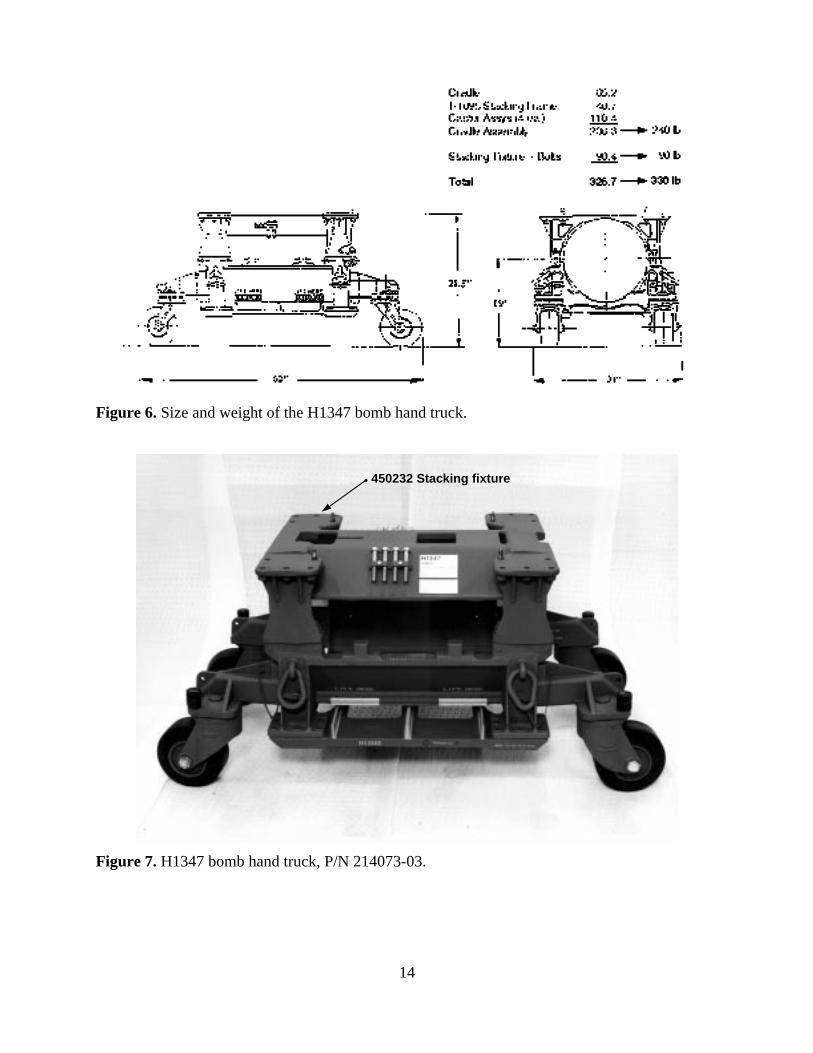
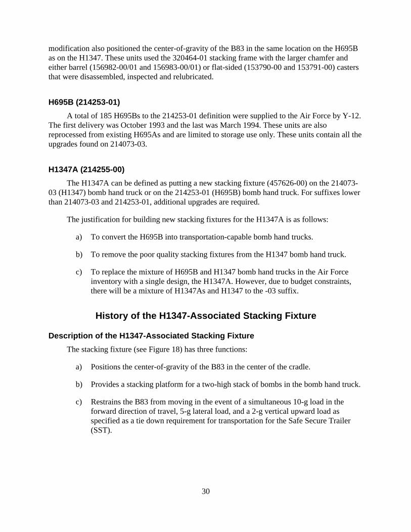
Bomb Hand Truck DescriptionThe B83 bomb hand truck (Figure 6) is 62 inches long, 31 inches wide, 28.5 inches high
and weighs 330 pounds. The bomb is positioned on the cradle assembly such that, with theaddition of the stacking fixture assembly, the bomb is encircled (Figure 1). Eight swing bolts onthe cradle assembly engage the stacking fixture to secure the bomb. The bomb lugs are engagedby cutouts on the stacking fixture to prevent both longitudinal and rotational movement of thebomb.
There are three configurations of stacking fixtures for the hand trucks: 1) H1347-associated, 2)H695B-associated, and 3) H1347A-associated.
The configuration of stacking fixture assembly defines the bomb hand truck as H1347 (Figure 7),H695B (Figure 3, upper), or H1347A (Figure 4). The same cradle assembly is used on all threebomb hand trucks. Table 1 is a breakdown of the product definition for the various versions ofthe three bomb hand trucks.
14
Figure 6. Size and weight of the H1347 bomb hand truck.
450232 Stacking fixture
Figure 7. H1347 bomb hand truck, P/N 214073-03.

15
Table 1. B83 bomb hand truck hardware definition.
Nomenclature Part No. SuffixH1347 214073 -00 -01 -02 -03H695B 214253 -00 -01H1347A 214255 -00
Cradle Assy 450441 -00 -01 -02 -03 -02 -03 -03Cradle (Cast) 172645 -01 -01 -01 -01 -01 -01 -01Cradle (Welded) 152781 -01 -01 -01 -01 -01 -01 -01
Swivel Caster (Barrel) 156982 -00/01 -00/01 -01 -02 -01 -02 -02Swivel Caster (Barrel) 156983 -00/01 -00/01 -01 -02 -01 -02 -02
Swivel Caster (Flat) 153790 -00 -00 -00 -01 -00 -01 -01Swivel Caster (Flat) 153791 -00 -00 -00 -01 -00 -01 -01
H1095 Stack. Frame 320464 -00 -00 -01 -01 -01 -01 -01H1095 Bolt (Grade 8) MS90727-64 Yes Yes Yes No Yes No NoH1095 Bolt (Grade 5) 456289 -00 -00 -00
Stk. Fxt. Bolt (Grd. 8) MS90728-172 Yes Yes Yes No Yes No NoStk. Fxt. Bolt (Grd. 5) 456290 -00 -00 -00Plate, Retaining 154304 -00 -00 -00 -01 -00 -01Bolt Pouch 457679 -00
Stacking Fixture Assy 450232 -00 -00 -00 -00Stacking Fixture Assy 249539 -00 -00Stacking Fixture Assy 249540 -00 -00Stacking Fixture Assy 457626 -00
The cradle assembly (Figure 8) includes the cradle, the H1095 stacking frame (Figure 9)and four caster assemblies. There are two types of cradles, fully interchangeable, one being a castcradle and one a welded cradle. There are also two types of caster assemblies used on the cradleassemblies, again interchangeable, one defined as a barrel caster (Figure 10) and the otherdefined as a flat-sided caster (Figure 11). The barrel caster mounting bracket is made from analuminum casting while the mounting bracket for the flat-sided caster uses structural aluminumtubing. All combinations of cradles and caster assemblies are allowed on the cradle assemblies.
The bomb hand truck part marking is on the stacking fixtures. Bomb hand trucks in field serviceinclude the 214073-00/-01/-02/-03 suffix for the H1347; 214253-00/-01 suffix for the H695B;and the 214255-00 for the H1347A.
B83 bombs may be stored in one- or two-high stacks with any combination of bomb hand trucks.However, only the H1347 or H1347A bomb hand trucks may be used for transportation. TheH695B cannot be used for over-the-road transportation as the stacking fixture modifications arenot designed for transportation environments.

16
Figure 8. Cradle assembly used for H1347, H695B, and H1347A bomb hand trucks.
Figure 9. H1095 stacking frame, P/N 320464-01.

17
Figure 10. Barrel-type caster assemblies.
Figure 11. H1640 Castering tool engaging wheel hub on flat-sided caster assembly.

18
Summary of the Problems and Concerns on the Bomb HandTruck Leading to the Quality Improvement Program
The problems and deficiencies that were identified on the H1347 bomb hand truck throughthe H-gear adequacy study, UR reviews, user interface meetings, and analysis are summarizedbelow:
a) Stacking fixture weld cracks on the H1347-associated stacking fixture (Figure 12).
b) Concern with meeting the 10-g load requirement with a tail-forward loadingconfiguration in the Safe Secure Trailer (SST).
c) Cracked welds on the female receptacle on the welded cradle for the caster mountingbracket (Figure 13).
d) Broken or cracked caster mounting brackets for the barrel casters (Figure 14).
e) Casters unlocking from the swivel lock position during transportation.
f) Poor condition of bearings (corrosion, no lubrication), seals, nuts, and dust caps incaster assemblies (Figure 15).
g) Caster tires rubbing against the H1095 stacking frame causing binding or tire damage.
h) The bolt that holds the retaining plate to mount the stacking fixture bolts breaks off inthe helicoil on the stacking fixture, or the helicoil gets damaged.
i) Longitudinal cracks in the stacking fixture bolts (Figure 16).
j) The Air Force requested alternate marking methods since spray paint was disallowed byDOE.
k) Caster callouts in TP B83-1 manual do not show which casters go where in the IPB(Illustrated Parts Breakdown).
l) Castering tools (H631 and H1216) cause damage to the barrel caster frame as straightsided forks gouge curved caster yoke (Figure 17).


20
Figure 14. Cracks in caster assembly mounting bracket (barrel caster).
Figure 15. Condition of bearings, seals, nuts, and dust caps in caster assembly.

21
Figure 16. Longitudinal cracks in stacking fixture bolts.

22
Figure 17. Typical damage to barrel-type caster from castering tool.
Note: Shar p edge/burr.

23
Table 2 is a compilation of URs against the B83 bomb hand truck.
Table 2. H1347 unsatisfactory reports (URs).
UR Number Date Comments
95-063 June 1983 Casters unlock during transit24-123 Dec 1983 Casters unlock during transit17-074 July 1984 Casters unlock during transit54-105 Oct 1985 Caster pin corroded42-046 April 1986 Casters unlock during transit011-017 Jan 1987 Manual inconsistent with caster suffix use082-107 Oct 1987 Manual inconsistent with caster suffix use014-117 Nov 1987 Manual inconsistent with caster suffix use046-068 June 1988 Holes in welds for caster mounting009-078 July 1988 Caster wobbles055-078 July 1988 Casters unlock during transit064-108 Oct 1988 Caster tire rubbing on stacking frame36TP108 Oct 1988 Caster tire rubbing on stacking frame078-118 Nov 1988 Tire separating from hub060-049 April 1989 Forklift use017-059 May 1989 Cracked weld in female caster receptacle on cradle086-099 Sept 1989 Broken caster mounting bracket058-119 Nov 1989 Broken caster078H010 Jan 1990 Caster tire rubbing on stacking frame014H020 Feb 1990 Hairline crack in stacking fixture bolts114-050 May 1990 Cracks in stacking fixture weld072-031 March 1991 Cracks in cradle084HG0391 March 1991 Loose swing bolts060-061 June 1991 Swing arm bolts loose062HG0691 June 1991 Broken helicoil on stacking fixture063BO0691 June 1991 Broken helicoil on stacking fixture043HG0991 Sept 1991 Void in caster weld053HG0991 Sept 1991 Cracks in stacking fixture welds087BO0991 Sept 1991 Cracks in stacking fixture welds062HG1091 Oct 1991 Cracks in stacking fixture welds017HG0392 March 1992 Cracked weld in female caster receptacle on cradle021HG0492 April 1992 Cracked weld in female caster receptacle on cradle053HG0692 June 1992 20 of 38 stacking fixtures have cracked welds011HG0792 July 1992 Cracks in stacking fixture welds (2 parts)006HG0792 July 1992 Casting voids in cradle033HG0892 Aug 1992 Casting voids in cradle038BO0892 Aug 1992 Cracks in stacking fixture welds076HG0992 Sept 1992 Broken helicoil on stacking fixture081HG0992 Sept 1992 Damaged caster frame from caster tool035HG1092 Oct 1992 Mfg. cracks in rolled lip on stacking fixture

24
Table 2. H1347 unsatisfactory reports (URs). (cont.)
UR Number Date Comments030HG1292 Dec 1992 Cracked weld in female caster receptacle on cradle009BO0293 Feb 1993 Cracked caster mounting bracket025BO0593 May 1993 Loose H1347 bolts050HG0593 May 1993 No space below part number; Swing bolts nuts
unserviceable046HG0993 Sept 1993 Damaged caster assembly006HG1293 Dec 1993 H695B felt and safety caps017HG0794 July 1994 Broken caster assembly001TP0894 Aug 1994 Shoring under single high stack021HG1194 Nov 1994 Loose caster assembly bolt033HG1194 Nov 1994 Defective caster assembly043HG0195 Jan 1995 Defective caster assembly062TP0295 Feb 1995 Manual discrepancy on forklift procedure047HG0395 March 1995 Tire separating from hub080HG0395 March 1995 Nine casters on seven bolsters unlocked during transit081HG0395 March 1995 Seven casters on six bolsters unlocked during transit073HG0595 May 1995 Five casters on three bolsters unlocked during transit001HG0795 July 1995 Fourteen casters on twelve bolsters unlocked during
transit051TP0895 Aug 1995 Request double stack towing with motorized vehicle035HG0995 Sept 1995 Cracked mounting brackets on three caster assemblies029HG1095 Oct 1995 Axle bolts on caster assembly below flush032HG1095 Oct 1995 Cracked mounting brackets on one caster assembly033HG1095 Oct 1995 Two casting voids on stacking fixture034HG1095 Oct 1995 Two rivets not seated on stacking fixture002HG1195 Nov 1995 Cracked and fractured mounting bracket on caster039HG1195 Nov 1995 Cracked mounting brackets on one caster assembly019TP0396 March 1996 Missing dust cover on caster assemblies manual note012BO0496 April 1996 Cracked caster mounting bracket032HG0297 Feb 1997 Loose swing bolts pins - 3 units001TP0697 June 1997 Manual change - Axle bolt replacement015TP0797 July 1997 H12-2 Manual change - Inspection procedures028HG1097 Oct 1997 Cracked weld (5/16”) on left pillar of H1347 stacking
fixture061TP1027 Oct 1997 Manual Change - Lifting procedure036HG1297 Dec 1997 a) Caster Assy – Large chip in caster lock area
b) Caster Assy – Tire separationc) Caster Assy – Crack near quick-release hubd) Caster Assy – Molding defect (bubble) in corner of caster

25
Summary of Quality Improvement Program Upgrades
Upgrade to H1347 (-03) and H695B (-01)
Beginning in the fall of 1993, bomb hand trucks delivered to the Air Force met the 214073-03 definition for the H1347 and the 214253-01 definition for the H695B (see Table 1). TheH1347 (-03) and the H695B (-01) bomb hand trucks contain the same upgrades (but havedifferent stacking fixtures). Changes and improvements to the hand truck include:
a) Upgraded the swivel caster definition to 156982-02 and 156983-02 for the barrel castersand 153791-01 and 153790-01 for the alternate flat-sided casters. The barrel casters withcam lock mechanisms were converted to the swivel lock option. Reprocessing wasimproved to include replacing worn or damaged bearings and seals. The casters wererelubricated. The plunger detent on the locking mechanism was properly adjusted andthe center bolt was properly tightened to allow normal swivel motion of the caster andnormal engagement of the plunger detent locking mechanism. These upgrades greatlyreduced the incidences of casters unlocking during transportation.
b) A larger chamfer on the H1095 stacking frame defined by 320464-01. This allows thecaster to swivel without binding and tearing rubber off the tire.
c) New Grade 5 stacking fixture bolts defined by 456290-00. These replaced Grade 8 boltsthat were susceptible to longitudinal cracking.
d) New Grade 5 stacking frame bolts defined by 456289-00, also replacing Grade 8 bolts.
e) A new retaining plate defined by 154304-01 to hold the stacking fixture bolts. The shankof the bolt that secures this plate could previously engage the helicoil causing damage.The new retaining plate prevents this from happening and is incorporated on the H1347(-03) and H695B (-01) bomb hand trucks.
f) Use of decals for marking the bomb hand trucks as an alternate marking method. Thiseliminates the need for painting.
g) A Retrofit Order defined by TP H1347-501 moved the bomb hand truck marking fromthe cradle assembly to the stacking fixture. Since the cradle assemblies for the H1347,H695B, and the H1347A bomb hand trucks are essentially the same, the type of stackingfixture used controls the definition of the bomb hand truck.
Manual Changes
a) Changes to the TP manuals were made to allow cracks (any length) in the welds for theH1347-associated stacking fixture after load testing resolved there were no safetyconcerns. However, product shipped from DOE to the Air Force covered byReprocessing Specification RS214073 limits the length of any individual crack to 2inches and the accumulative length of all cracks to less than 8 inches, total.

26
b) Changed TP45-51 manual allowing only nose-forward configuration for both the one-and two-high stack loading in the Safe Secure Trailer (SST).
c) Changes to the TP manuals allowing cracks up to 2.5 inches total length in the welds foreach of the cradle receptacles for the mounting brackets for the four caster assemblies.However, product shipped from DOE to the Air Force covered by ReprocessingSpecification RS214073 or RS214255 limits the cracks to 1-inch length in each of thefour cradle receptacles.
d) Changes to the TP manuals to control conditions and speeds for transport by truck ortrailer or by towing with a motorized towing vehicle. Reducing the shock and vibrationenvironment will reduce cracking in the welded region of the cradle receptacle formounting the caster. Cracking of the caster mounting bracket will also be reduced. (SeeTable 3 defining the new towing and truck/trailer transport conditions.)
e) Changes to the TP manuals to update base spares callouts and to correct many problemsand deficiencies.
Table 3. Towing and truck/trailer transport requirements.
TowingOne-High StackOver smooth, hard surfaces for a distance ofup to 1 mile at speeds not to exceed 5 mph.
Two-High StackOver smooth, hard surfaces for a distance of up to1,000 feet at a slow walking speed (approximately 1mph).
Truck or Trailer TransportOne-High StackNo shoring required at speeds less than 20mph. Shoring required at speeds greater than20 mph.
Two-High StackShoring required at all speeds.
Upgrade to H1347A
The processing of the bomb hand truck to H1347A involved using the upgrades to theH1347 (-03) or the H695B (-01) bomb hand trucks with the following:
a) A new H1347A-associated stacking fixture defined by 457626-00 to replace all of theH695B-associated and a portion of the H1347-associated stacking fixtures.
b) A new bolt pouch (457679-00) to hold the stacking fixture bolts for the H1347A-associated stacking fixture. This allows access to the bolts without using a tool that wasrequired to disengage the retaining clip used on the H1347- and H695B-associatedstacking fixtures.

27
Other Changes
A new castering tool, the H1640, replaced the H631 and H1216 for the B83. The new toolwill not gouge the frame (yoke) on the barrel casters.
Possible Future Upgrades
A development program was started in January 1996 to design a stronger caster mountingbracket for the barrel caster assembly. The barrel caster assembly uses a cast aluminum mountingbracket that cracks under normal usage conditions as reported by URs.
Stockpile Upgrade Program to H1347AA new H1347A-associated stacking fixture defined by 457626-00 was implemented in
1995. When this stacking fixture is used with cradle assemblies from the H1347 (-03) or theH695B (-01), the resulting bomb hand truck is the H1347A (-00) (see Table 1).
The Stockpile Upgrade Program to H1347A is described in Product Change Proposal 6-93and the procedures for the field portion of the retrofit are found in TP H1347-502. The originalplan called for the new stacking fixture to replace all stacking fixtures on both the H1347s andH695Bs (approximately 800), which would result in the Air Force having only one bomb handtruck in their inventory. This would be the H1347A. Due to budget restraints, only 415 newH1347A-associated stacking fixtures are being fabricated by AlliedSignal/FM&T at the rate of15 per month. The Upgrade Program to H1347A will upgrade the 329 storage-only H695Bs and86 of the H1347s into H1347As. This is done by adding improvements to bring the H695B to the-01 version and the H1347 to the -03 version and then exchanging the stacking fixture with anew H1347A-associated stacking fixture.
The Air Force inventory of 329 H695B is further broken down to 146 H695B (-00) and 183H695B (-01). The H1347s are a mix of -00, -01, -02, and -03s.
The 146 H695Bs (-00) were returned from the Air Force to AlliedSignal/FM&T forconversion into H1347A. This phase was started in November 1995 and was completed in July1996.
The 183 H695B (-01) will be converted at Air Force facilities by sending the H1347A-associated stacking fixture directly to the Air Force for the stacking fixture exchange. This willbe during the time period of October 1996 through January 1998.
The remaining 86 H1347A-associated stacking fixtures will be sent to Pantex to upgradeH1347 to H1347A in support of Mod 1 deliveries. This will extend over the time period of June1996 through February 1997. All other Mod 1 and quality assurance units delivered to the AirForce from Pantex are to the H1347 (-03) configuration. The Air Force inventory will thenconsist of H1347 and H1347A bomb hand trucks, all of which can be used for either storage ortransportation purposes.

28
The H1347A upgrade will be completed by March 1998 with the Air Force inventory atthat time totaling 415 H1347As. The upgrade of H1347 to the -03 configuration will be ongoingas some -00s, -01s, and -02s will be returned to Pantex from the Air Force with quality assuranceunits that are scheduled throughout the life of the B83 program.
Bomb Hand Truck Definition and HistoryThe bomb hand trucks in the Air Force inventory include the H1347 (214073-00/01, -02
and -03 suffix) and the H695B (214253-00 and -01 suffix). The overall plan is to convert all 329of the H695Bs into H1347As (214255-00) and 86 of the H1347s into H1347As. The remainderof the H1347s will be upgraded to H1347 (-03 suffix).
The following is a more detailed description of the bomb hand trucks listed in Table 1along with the histories of their development.
H1347 (214073-00/01)
The original build for the B83 program was the H1347, P/N 214073-00/01. In the mid-1980s approximately 209 of the H1347s were fabricated at Tura Inc., Folcroft, PA and 370 atAllied-Mechanical Products, Ontario, CA. Approximately 685 new casters were fabricated atAerol Corp., Los Angeles, CA (4 required per bomb hand truck) but the majority of casters werereused from the H695A. The cradle assemblies, H1095 stacking frames, and other parts werereused from the H695A program. The cradle assemblies (450441) were reprocessed fromexisting H695A bomb hand trucks using reprocessing requirements from SS450441. TheH695A-associated stacking fixtures were replaced by a new stacking fixture (450232-00) withcast end pieces welded to a center section. A new stacking fixture was required because of achange in the way the bomb interfaced with the hand truck. The B43 had an attachment on theside of the bomb that bolted directly to a lug on the cradle rail, while the B83 bomb hand truckcaptured the bomb lugs in cutouts on the new stacking fixture.
The H1095 stacking frame (320464-00), which was a separate part for the H695A, wasreused but became part of the 450441 cradle assembly. The 214073-00 bomb hand trucks used acam lock device on the caster assemblies that lead to URs from the Air Force because of casterunlocking problems. Midway through the original build, changes were made to use a swivel lock,and the suffix of the cradle and bomb hand truck raised. However, the caster definition was notchanged, and new caster assemblies fabricated by Aerol still contained the cam lock design.Since the new caster assemblies were not upgraded with swivel locks, raising the suffix on thecradle and bomb hand truck was ineffective in controlling product definition on the casterassemblies.
H1347 (214073-02)
As a result of the problems identified in the H-gear adequacy study, improvements werestarted to the H1347 bomb hand truck. The additional 62 H1347s supplied by Y-12 to the AirForce from February 1993 through April 1993 were reprocessed to the 214073-02 version thatincluded a larger chamfer on the H1095 stacking frame (320464-01) to solve a problem with the

29
caster binding against the stacking frame. Also, all casters were disassembled, damaged bearingsand seals were replaced, and the bearings were relubricated. The casters used were 156982-00/01and 156983-00/01 referred to as barrel casters (many that still contained the cam lock). Analternate version of casters (153790-00 and 153791-00), referred to as flat-sided casters, were notused in this production.
H1347 (214073-03)
Continued improvements to resolve problems on the H1347 were made on the 214073-03definition. This version, started in November 1993, supports all B83 shipments (Mod 1 and QAreturns) from Pantex to the Air Force. The improvements include:
a) The larger chamfer on the stacking frame defined by 320464-01.
b) Upgraded swivel casters defined by 156982-02 and 156983-02. (Alternates are 153790-01 and 153791-01). The upgraded 156982-02 and 156983-02 swivel casters replaced allcam locks with swivel locks. The swivel casters were also disassembled, inspected, andrelubricated. The 153790-01 and 153791-01 flat-sided casters had covers added to thelocking handles besides the disassembly, inspection, and relubrication process.
c) New Grade 5 stacking frame bolts defined by 456289-00 and new Grade 5 stackingfixture bolts defined by 456290-00. The original Grade 8 stacking fixture bolts had beenthe subject of URs because of bolt cracking attributed to an improper quenching process(Figure 16). This, in addition to finding suspect/counterfeit bolts, lead to a redefinition ofthe stacking fixture and stacking frame bolts from a Grade 8 to a Grade 5 requirementand required that replacement bolts from military spares be eliminated and replaced bybase spares. Base spare items for the Air Force are purchased by DOE throughAlliedSignal/FM&T.
d) New retaining plate defined by 154304-01. The retaining plate is used to clip thestacking fixture bolts to the stacking fixture for storage when the bomb hand trucks arein the single-stack configuration. A 1/4-28 UNC bolt with an unthreaded shank is used tofasten the retaining plate to the stacking fixture engaging an insert in the stacking fixture.When the stacking fixture bolts are removed and the 1/4-28 bolt tightened to keep theretaining plate from rattling, the shank engages the insert. This led to URs when theshank engaged the threaded insert and the insert was either damaged or the bolt broke offin the insert. The retaining clip was redesigned so that the shank of the 1/4-28 bolt doesnot engage the insert whether or not the stacking fixture bolts are in the clip.
H695B (214253-00)
A total of 144 H695Bs to the 214253-00 definition were reprocessed at Y-12 withdeliveries to the Air Force from April 1993 through September 1993. These units werereprocessed from existing H695As and are limited to storage use only. They can be doublestacked with other H695Bs or H1347s. The stacking fixture from the H695A was used butmodified to 249539-00 or 249540-00, which allowed capture of the B83 by the bomb lug. The
30
modification also positioned the center-of-gravity of the B83 in the same location on the H695Bas on the H1347. These units used the 320464-01 stacking frame with the larger chamfer andeither barrel (156982-00/01 and 156983-00/01) or flat-sided (153790-00 and 153791-00) castersthat were disassembled, inspected and relubricated.
H695B (214253-01)
A total of 185 H695Bs to the 214253-01 definition were supplied to the Air Force by Y-12.The first delivery was October 1993 and the last was March 1994. These units are alsoreprocessed from existing H695As and are limited to storage use only. These units contain all theupgrades found on 214073-03.
H1347A (214255-00)
The H1347A can be defined as putting a new stacking fixture (457626-00) on the 214073-03 (H1347) bomb hand truck or on the 214253-01 (H695B) bomb hand truck. For suffixes lowerthan 214073-03 and 214253-01, additional upgrades are required.
The justification for building new stacking fixtures for the H1347A is as follows:
a) To convert the H695B into transportation-capable bomb hand trucks.
b) To remove the poor quality stacking fixtures from the H1347 bomb hand truck.
c) To replace the mixture of H695B and H1347 bomb hand trucks in the Air Forceinventory with a single design, the H1347A. However, due to budget constraints,there will be a mixture of H1347As and H1347 to the -03 suffix.
History of the H1347-Associated Stacking Fixture
Description of the H1347-Associated Stacking Fixture
The stacking fixture (see Figure 18) has three functions:
a) Positions the center-of-gravity of the B83 in the center of the cradle.
b) Provides a stacking platform for a two-high stack of bombs in the bomb hand truck.
c) Restrains the B83 from moving in the event of a simultaneous 10-g load in theforward direction of travel, 5-g lateral load, and a 2-g vertical upward load asspecified as a tie down requirement for transportation for the Safe Secure Trailer(SST).

31
(a) Top side (b) Under side
Figure 18. H1347-associated stacking fixture, P/N 450232-00.
The most critical function of the stacking fixture is restraining the movement of the B83 in the10-g, 5-g, 2-g accident scenario for the SST. The primary interface between the stacking fixtureand the B83 are the bomb lugs. When the B83 is loaded nose forward in the direction of travel,both lugs are forced directly into the strongest area of the stacking fixture casting. Unfortunately,when the weapon is loaded tail forward in the direction of travel, only one lug will make contactwith the stacking fixture (see Figure 1). The single point of contact is not with the strong archedcasting but with a 3/4-inch plate, (450234-00) weakened by a slot for clearance for the H1004bomb hoisting adapter. Testing showed the stacking fixture does not meet the 10-g requirementfor tail-forward loading in the direction of travel.
Approximately 580 new stacking fixtures defined by 450232-00 were fabricated for theH1347 bomb hand trucks in the mid-1980s. A center section weldment consists of two aluminumbraces (450233-00) welded at a 45° angle to a 3/4-inch-thick aluminum center captivating plate(450234-00) that restrains the forward lug in the aft direction. The braces on the center sectionweldment are then welded to two arched end pieces defined by 450237-00 (an aluminum alloycasting, permanent mold, 356 per AMS 4284) using ER5183 or ER5356 welding rod. Thewelding specification and inspection is per 9912117, Class II. There are a total of four welds: oneon each end of each brace separating the two aluminum castings. The brace and correspondingweld cross-section is approximately 8 inches by 0.375 inch. The weld is made with passes onboth the inside and outside surfaces of the stacking fixture. The entire welded assembly ismachined as a unit. The lug capture cutouts are end milled. The bomb contour was lined boredinto the assembly, simultaneously cutting the B83 diameter into the casting and the center sectionstiffener of the stacking fixture. This provided a center section that matched the B83 diameterand allowed full capture of the edge of the lug.

32
Welding of the center section to the end castings was difficult. Due to the design of thecasting in the areas of the welds, a uniform weld cross section was impossible to produce. Theweld cross section varied from a butt to a fillet. The symmetry of the weldment also createdproblems for the welder due to limited access. Welding also created warpage of the assembly,requiring it to be machined after welding. Control of the welding process was difficult.
Weld Cracking Problem
The first major indication of weld quality problems on the stacking fixture was reported bythe Air Force via UR Code No. 053HG0692 dated June 22, 1992 where 20 of 38 units inspectedwere reported as cracked. The cracks are in the outboard regions of the 45o plates where thecenter section is welded to the end castings (Figure 12). An on-site inspection by an evaluationteam consisting of Sandia, AlliedSignal/FM&T, and DOE/AL/WQD personnel was completedon July 21, 1992. Two H1347s with the cracked stacking fixtures were sent toAlliedSignal/FM&T for evaluation. The cracks were characterized as crater cracks with somepropagating to form longitudinal cracks up to 1.1 inches in length. There was lack of fill of theweld crater at the time of manufacture and the cracks formed upon solidification of the weldmetal. Some stacking fixtures had cracks in three of the four welds. The welding specificationdoes not allow crater cracks, cracks in the weld bead, or in the parent material. Product withthese defects do not meet the design requirements and should not have been accepted for WRuse.
An interim UR response dated August 6, 1992 from SNL/Dept 5513 to the Commander,Field Command / Defense Nuclear Agency allowed only stacking fixtures without cracks to beused in over-the-road operations that required a prescribed tie down configuration, such as theTP45-51 series. This includes transportation in the Safe Secure Trailer, aircraft, and trailer tiedown modes. Normal operations with the H1347s, including storage and forklift movement ofweapons, were unrestricted with stacking fixtures having weld cracks of less than 1 inch inlength. The interim response also requested an asset-wide inspection of all stacking fixtures inthe Air Force inventory.
A Special Instructions Engineering Release (SIER 920472SL) was released to the DOEcomplexes requiring an asset-wide inspection and imposed the same transportation restrictions asplaced on the Air Force. The SIER required special marking on acceptable inspected units andalso defined repair criteria.
An asset-wide inspection program for the H1347-associated stacking fixture, includingboth Air Force and DOE inventories, showed 106 out of 529 units inspected to be cracked (20%).These inspections identified cracks that were visible through the paint.
Weld Evaluation and Repair Program
The weld evaluation and repair process work carried out at AlliedSignal/FM&T showed theoriginal welds did not meet drawing requirements and exhibited significant lack of penetration,lack of fusion, weld crater cracks, undercut and overlap (Figure 19). The weld repair processproved to be difficult and labor intensive. ES&H concerns were a factor as welding of a painted

33
structure created fumes. This required stripping a significant amount of paint at a high labor cost.When the defective welds were removed and new beads started, contamination in the old weldsbubbled up causing voids in the new welds. The weld repair process could not control distortionof the stacking fixture or limit it to acceptable amounts. Stacking fixture pull tests on weldrepaired units showed no increase in joint strength. The weld repair process proved to be capableof improving appearance of the stacking fixture but did nothing to increase quality or improvestrength of the welded joint. Later testing showed weld joint strength not to be a safety issue intransportation environments.
(a) (b)
(c) (d)
Figure 19. Cross-section of welds on H1347-associated stacking fixture.
34
H1347-Associated Stacking Fixture and Bomb Hand TruckTesting Program
Weld Pull Testing on the H1347-Associated Stacking Fixture
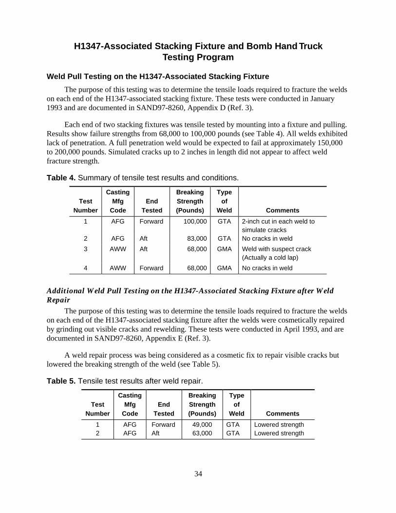
The purpose of this testing was to determine the tensile loads required to fracture the weldson each end of the H1347-associated stacking fixture. These tests were conducted in January1993 and are documented in SAND97-8260, Appendix D (Ref. 3).
Each end of two stacking fixtures was tensile tested by mounting into a fixture and pulling.Results show failure strengths from 68,000 to 100,000 pounds (see Table 4). All welds exhibitedlack of penetration. A full penetration weld would be expected to fail at approximately 150,000to 200,000 pounds. Simulated cracks up to 2 inches in length did not appear to affect weldfracture strength.
Table 4. Summary of tensile test results and conditions.
TestNumber
CastingMfg
CodeEnd
Tested
BreakingStrength(Pounds)
Typeof
Weld Comments
1 AFG Forward 100,000 GTA 2-inch cut in each weld tosimulate cracks
2 AFG Aft 83,000 GTA No cracks in weld
3 AWW Aft 68,000 GMA Weld with suspect crack(Actually a cold lap)
4 AWW Forward 68,000 GMA No cracks in weld
Additional Weld Pull Testing on the H1347-Associated Stacking Fixture after WeldRepair
The purpose of this testing was to determine the tensile loads required to fracture the weldson each end of the H1347-associated stacking fixture after the welds were cosmetically repairedby grinding out visible cracks and rewelding. These tests were conducted in April 1993, and aredocumented in SAND97-8260, Appendix E (Ref. 3).
A weld repair process was being considered as a cosmetic fix to repair visible cracks butlowered the breaking strength of the weld (see Table 5).
Table 5. Tensile test results after weld repair.
TestNumber
CastingMfg
CodeEnd
Tested
BreakingStrength(Pounds)
Typeof
Weld Comments
1 AFG Forward 49,000 GTA Lowered strength2 AFG Aft 63,000 GTA Lowered strength

35
Forward and Aft Loading of Bomb in H1347 Bomb Hand Truck to Simulate SST“g” Loading Requirement
The purpose of this testing was to determine if a safety issue existed when using crackedH1347-associated stacking fixtures in the Safe Secure Trailer (SST) transport environment of 10-g in the direction of travel. This test was conducted in February 1993, and is documented inSAND97-8261, Appendix A (Ref. 4).
Four tests were performed using a section of the B83 bomb with bomb lugs engaging thestacking fixture on the H1347 bomb hand truck. The first two tests were on a one-high stackconfiguration with the bomb nose in the forward direction of travel. The H1347-associatedstacking fixture had the center section removed to simulate a worst-case condition where theweld had completely failed. Test loads of 50,000 pounds were applied to the bomb simulating a20-g load (10-g requirement). Displacement of the bomb to the bomb hand truck was negligible.
The third test was on a two-high stack with the bomb nose in the forward direction oftravel. The center sections of both H1347-associated stacking fixtures were removed. A test loadof 60,000 pounds was applied to the upper bomb. Displacement of the bomb to the bomb handtruck was negligible.
The fourth test was on a one-high stack with the bomb tail in the forward direction of travel(10-g requirement) and the center section of the H1347-associated stacking fixture intact. Thebomb started to slip relative to the bomb hand truck at a load of 25,550 pounds (10 g). At a testload of 30,000 pounds (12 g), the bomb had slipped 1.625 inches. The bomb lug slides under thecenter section of the stacking fixture. This test shows the stacking fixture is marginal in meetingthe 10-g requirement in the forward direction of travel with the tail orientated in the forwarddirection. This led to a manual change to disallow tail-forward orientation of the bomb in theSST.
The 5-g requirement in the aft direction is met with a design margin of two when the bombis oriented with the nose forward in the SST.
Conclusion and Recommendations Regarding the H1347-Associated StackingFixture
The conclusions reached from the testing program are:
a) Cracked welds on the stacking fixture do not constitute a safety concern for single-or double-stacked configurations if the bomb is orientated with the nose in theforward direction of travel (10-g requirement) for Safe Secure Trailer (SST)transport.
b) There is a safety concern when the B83 bomb is orientated with the tail in theforward direction of travel (10-g requirement) for Safe Secure Trailer (SST)transport. This concern is independent of whether or not any welds are cracked asthe bomb lug slides under the center section.
c) Weld joint strength or quality is not improved by weld repair.
36
d) Product quality issues must be resolved for customer satisfaction.
Recommendations incorporated following the testing and evaluation program on the H1347stacking fixture were:
a) Remove the restrictions in the response to UR Code No. 053HG0692. Use ofH1347s with cracked (any length) stacking fixtures on over-the-road operationsrequiring tie down configurations was allowed. However, product shipped fromDOE to the Air Force covered by Reprocessing Specification RS214073 limits thecracks to 2 inches in length in each of the four welds.
b) Make changes to the TP45-51D manual requiring the bomb to be orientated withthe nose in the forward direction of travel in either the one- or two-high stackconfiguration for the Safe Secure Trailer (SST) transport. Tail-forward orientationin the direction of travel was eliminated.
c) Discontinue the weld repair development program on the H1347-associatedstacking fixture at Allied Signal/FM&T.
d) Resolve product quality issues by designing a new stacking fixture, 457626-00,resulting in the H1347A bomb hand truck when incorporated. This stacking fixturewas intended to replace the 450232-00 stacking fixture on the H1347 and thestacking fixture on the H695B. However, budget constraints limited the number ofunits built to 415 with 329 going on H695Bs and 86 on H1347s.
History of the H695B-Associated Stacking FixtureLead design efforts for the H695B-associated stacking fixture were directed by Larry
Brown, 2265. This work started in late 1992 with the request from the Air Force for 391additional bomb hand trucks. (In order to meet schedule requirements, it was agreed by DOE andthe Air Force that the H695Bs would be designed for storage only.) The requirement was met bysupplying 329 H695B bomb hand trucks processed from available H695As at Y-12. Theremaining 62 bomb hand trucks were H1347s reprocessed at Y-12 as H1347 (-02).
Processing of the H695A bomb hand truck into the H695B is covered under SS214253.The major modification is converting the existing H695A-associated stacking fixture into theH695B-associated stacking fixture. The H695A-associated stacking fixture used for the B43bomb had attachment points to lugs on the side of the bomb. The B83 requirement is to capturethe forward bomb lug with the stacking fixture.
Two versions of stacking fixtures exist on the H695A defined by 172644 (casting) and152782 (welded). The 172644 stacking fixture is modified per 249539 while the 152782 ismodified per 249540. Both of these modifications require machining the lug cutout in theforward section of the stacking fixture and adding a 3/8-inch-thick aluminum plate to the top ofthe stacking fixture to capture the bomb lug. The plate is attached by 10-32 UNF screws in sixplaces.

37
Load Testing
Load test results on this stacking fixture are documented in SAND97-8261, Appendix C(Ref. 4). Test results show the cast cradle started to fail at 27,800 pounds in the forward directionand 8,600 pounds in the aft direction equivalent to 11.1 and 3.4 g, respectively. Requirement is10 g in the direction of travel and 5 g in the aft direction. The welded stacking fixture started tofail at 28,100 pounds in the forward direction and 8,200 pounds in the aft direction, equivalent to11.2 and 3.3 g, respectively.
Development of the H1347A-Associated Stacking FixtureLead design efforts for the H1347A-associated stacking fixture (Figure 20) were directed
by Karl Arnold, a Allied Signal/FM&T engineer on assignment to SNL/CA from February toDecember 1993. Karl assembled a team to brainstorm ideas on creating a new design. The teamproduced six proposals: two involved rework of the old design and four involved building newproduct. Lorenzo Asia, 2282, was instrumental in working out the details of each concept todetermine its feasibility. The most attractive option involved bolting in the center section asopposed to welding in the center section. A prototype unit was built using modified castings froma used H1347-associated stacking fixture. Center sections were machined from 6061 and 7075aluminum plates of various thickness (5/8, 3/4, and 1 inch), bolted to the modified cast endpieces, and tested in both forward and aft direction loading.
Figure 20. H1347A-associated stacking fixture.
The center section is the critical component in the design. Considerable emphasis wasplaced on improving the performance of the stacking fixture in the aft loading direction. Therequirements are a simultaneous 10-g forward direction, 5-g lateral, and 2-g vertical load on thebomb weighing 2,500 pounds in a one- or two-high stack in the Safe Secure Trailer (SST). Aftdirection loading requirement is 5 g. Our goal was to design the stacking fixture to two times thelongitudinal load requirements. Since the manuals were changed to limit B83 transportation to anose-forward direction only in the SST, our design goals were 50,000 pounds load capability inthe forward direction and 25,000 pounds load capability in the aft direction.
38
Center Section Design and Test Results
The prototype stacking fixture proved to be a valuable asset in the development of theoptimum center section design. The bolted configuration allowed experimentation with manydifferent center sections and replication of the experiments. The prototype stacking fixture wasused in approximately 16 tests to evaluate design changes. A summary of the stacking fixturedevelopment tests for the center section are shown in Table 6 below.
Table 6. Summary of stacking fixture development tests for the center section.
CenterPlate TestNumber
Thickness (1)
(inch)Directionof Load
Load(pounds) Displacement Comments
Total (3)
(inch)Relative (4)
(inch)
One-High Stack Configuration1 0.625 Fwd 50,000 0.808 No visual
damage2 0.625 Aft 30,000 0.900 Lug slipped3 0.625(2) Aft 16,700 0.875 Lug slipped4 0.625 Aft 30,000 0.9105 0.750 Aft 30,000 0.6456 0.750 Aft 30,000 0.6207 0.750 Aft 30,000 0.550 0.0908 0.750 Aft 30,000 0.550 0.0759 1.000 Aft 30,000 0.64510 1.000 Aft 30,000 0.70011 1.000 Aft 30,000 0.520 0.25012 1.000 Aft 30,000 0.515
50,000 1.020Assembly “B”Configuration
13 1.000 Fwd 15,200 0.450 Lug slipped14 1.000 Fwd 18,000 0.500 Lug slipped
30,000 2.020 1.75015 1.000 Fwd 30,000 0.350 0.220
Two-High Stack Configuration16 0.750 Fwd 60,000 0.655
(1) All plates are 6061-T6 except as noted.(2) 7075-T6 plate.(3) Total displacement is stacking fixture movement with respect to the static frame.(4) Relative displacement is stacking fixture movement with respect to the bomb.
The final design for the center section was stock 5/8-inch-thick 6061-T6 aluminum plate.Although the center section went through many iterations the following illustrates the majordifferences from the old design.
39
• The center section was bolted to the cast end pieces rather than welded. The cast endpieces are similar to the H1347-associated stacking fixture casting except for someadded material in the region of the bolted interface.
• The center section was made from a single flat plate of 6061-T6 aluminum, 5/8-inchthick; no welded-on side flanges were used to increase flexural strength.
• The center section inner contour was changed from curved to flat. Contact with thebomb lug changed from curved to tangent.
• The cutout in the center section to engage the bomb lug was changed by adding materialover the lug engagement area to increase aft direction loading capability.
Casting Design and Casting Process
The casting for the two end pieces for the H1347A-associated stacking fixture is defined by457589. This is an aluminum alloy (A356-T6) dry sand casting per SS457589. Two castings areused for each stacking fixture assembly, one at each end of the flat center plate. These castingsare similar to the 450237 casting used on the H1347-associated stacking fixture. One change isthe addition of approximately 1 3/8-inch of material near the interface to the bolted-on centersection. Material properties in critical areas of the casting are 28-ksi tensile strength, 20-ksi yieldstrength, and 2% elongation; while in noncritical areas requirements are 26-ksi tensile yield, 18-ksi yield strength, and 1% elongation. These properties are determined by cutting up castings tomachine tensile bars. Requirements in SS457589 require one casting be cut up for each 100castings produced for the first 500 castings and one casting thereafter for each 200 castingsproduced. Mechanical property requirements for as-cast integral tensile bars made with thecastings require 34-ksi tensile yield, 24-ksi yield strength, and 3.5% elongation.
AlliedSignal/FM&T has the production responsibility to fabricate the H1347A-associatedstacking fixture and contracted the casting of the two end pieces to Hitchcock Industries, Inc.located in Bloomington, Minnesota. The castings were produced over the time period fromJanuary 1994 to June 1996 with a total production of approximately 900. These supported the415 stacking fixtures to be shipped from AlliedSignal/FM&T over the time period from October1995 to February 1998 for the upgrade of the H695B and a portion of the H1347 bomb handtrucks to the H1347A.
The dry sand casting process involves making two cores for each stacking fixture castingusing a gas activated binder (Isocure) process. The pattern for the casting is composed of twolarge aluminum boxes with positive replicates (made of epoxy-filled metal) of one half of thecasting in each box. Main gating flow is created by aluminum passageways in each box. Riserareas are created by painted wooden inserts. Custom iron chills are placed in the pattern toachieve optimum material properties. The cope and drag molds are created by filling these twopattern boxes with sand, compacting, and removing the chemically bonded sand mold. (There aretwo castings per mold.)
The cores are placed within the sand molds and the molds are assembled together andsealed. A pouring trough is attached to the top of the mold to aid in stabilizing the introduction of

40
liquid metal in the pouring step. After chemistry checks, the liquid metal is poured with handladles into the mold assembly. Approximately 220 pounds of metal is required for each mold(two castings). A disc for chemical evaluation is poured at this time. After pouring, the mold isallowed to cool.
The mold assembly is placed on a vibratory shaker that removes most of the sand material.Hand tools are used to remove any remaining mold material. The risers and gates are thenremoved from the castings with bandsaws. Integral appendages (test bars) are also cut off at thistime and labeled for traceability.
Castings are heat treated and quenched to achieve a soft T4 condition. A fixture is used tohelp check for straightness of each stacking fixture casting. The castings are put in an agingfurnace and taken to optimum material properties (T6 condition). The casting lot is now createdand test bars are sent for on-site tensile testing.
Castings are 100% fluorescent penetrant inspected and undergo sampling for radiographicinspection. Defects can be weld repaired but reheat treating is then required, which will create anew casting lot. Castings are dimensionally inspected using fixture and/or hand gages.Certifications are checked and the castings are shipped. Included with each casting lot shipmentare chem discs (one per melt), x-ray film, four appendages, hardness certs, and results from twotested appendages.
H1347A-Associated Stacking Fixture Testing Program
Vibration Tests to Qualify New H1347A-Associated Stacking FixtureThe purpose of this testing was to qualify the stacking fixture to vibration environments for
B83 transportation. These tests were conducted in July 1995 and are documented in SAND97-8262, Appendix C (Ref. 5).
The B83 VTU-1 test unit assembly endured a five-hour, random vibration per thetransportation vibration requirements in the z-axis. Post-test inspection of the H1347A-associatedstacking fixture and the bolt pouches showed no irregularities or damage.
Structural Tests to Qualify New H1347A-Associated Stacking FixtureThe purpose of this testing was to qualify and assess the design margin of the stacking
fixture to react the load of the B83 bomb through the bomb lug/stacking fixture interface for theSST requirements of 10 g in the forward direction of travel. Qualification tests to 5 g in the aftdirection were also performed. These tests were conducted in July and August, 1995 and aredocumented in SAND97-8262, Appendix A (Ref. 5).
Four tests were performed: the first three on the H1347A-associated stacking fixture andthe fourth on an H1347-associated stacking fixture. All tests were on a one-high stackconfiguration.

41
In the first test simulating the 2,500-pound B83 bomb, the nose was oriented in the forwarddirection of travel. Both bomb lugs engaged the stacking fixture. A test load of 75,000 poundswas applied to the bomb creating a 30-g load (10-g requirement) on the bomb lug/stackingfixture interface. Displacement of the bomb to the bomb hand truck was 0.17 inch.
The second test pulled the bomb in the aft direction where only the forward bomb luginteracts with the stacking fixture. A test load of 37,500 pounds was applied to the bomb creatinga 15-g load (5-g requirement) on the bomb lug. Displacement of the bomb to the bomb handtruck was 0.32 inch at a 25,000-pound load and 1.20 inches at the 37,500-pound load. The bombhad started to slip but was still restrained by the stacking fixture.
The third and fourth tests were on a B83 assembly D configuration (tail section removed—equivalent bomb weight is 1,800 pounds). The bomb is shifted aft in the bomb hand truck so thatthe forward bomb lug engages a center cutout on the stacking fixture. The third test used thesame H1347A-associated stacking fixture as used in tests one and two. In the fourth test, the setup was the same, but a H1347-associated stacking fixture was substituted as no previous datawas available on this configuration.
In the third test, a test load of 72,000 pounds was applied to the assembly D creating a 40-gload (10-g requirement) on the bomb lug/H1347A-associated stacking fixture interface.Displacement of the bomb to the bomb hand truck was 0.98 inch.
In the fourth test on the H1347-associated stacking fixture, a test load of 36,000 poundswas applied to the assembly D creating a 20-g load (10-g requirement) on the bomb lug/H1347-associated stacking fixture interface. Displacement of the bomb to the bomb hand truck was 1.85inches.
Conclusions Regarding the H1347A-Associated Stacking Fixture
The conclusions reached from the testing program are:
a) The H1347A-associated stacking fixture with the B83 bomb meets the SST requirementof 10-g loading in the forward direction of travel. With the bomb nose in the forwarddirection it was tested to a 30-g equivalent load. Displacement of the bomb to the bombhand truck was 0.17 inch.
b) The H1347A-associated stacking fixture with the B83 bomb meets the SST requirementof 5-g loading in the aft direction. With the bomb nose in the forward direction it wastested to a 15-g equivalent load in the aft direction. Displacement of the bomb to thebomb hand truck was 1.20 inches.
c) The H1347A-associated stacking fixture with the B83 assembly D configuration meetsthe SST requirement of 10-g loading as it was tested to a 40-g equivalent load with0.98-inch displacement.
42
Conclusion Regarding the H1347-Associated Stacking Fixture for Assembly D
The H1347-associated stacking fixture with the B83 assembly D configuration meets theSST requirement of 10-g loading as it was tested to a 20-g equivalent load with 1.85-inchdisplacement. This design is not as strong as the H1347A-associated stacking fixture.
Cradle and Caster Assembly EvaluationThe same cradles and casters are used on the H1347, H1347A, and H695B bomb hand
trucks. There have been numerous URs involving cracks with the cradles and casters (seeTable 2). Cracked welds in the female receptacle for the caster mounting bracket on the weldedcradle (Figure 13) and cracked mounting brackets on the cast barrel caster (Figure 14) have beenan issue.
The environments for the bomb hand truck include truck and trailer transport, towing, andforklift movements in both one-high and two-high stack configurations and aircraft transport inthe one-high stack configuration. Vibration and shock requirements are found in the Stockpile-to-Target Sequence (STS) manual (Ref. 6) and the Manufacture-to-Stockpile Sequence (MSS)manual (Ref. 7). Worst-case environment in the vertical direction is estimated at approximately 5to 7 g in the two-high stack configuration and 7 to 10 g in the one-high stack configuration.
Vertical load tests were performed on the cradle with casters to evaluate the effect of theweld cracks in the receptacle for the caster mounting bracket. The strength of the caster mountingbracket was also determined from these tests. Towing tests to measure shock and vibration inputswere also performed. A summary of the testing and analysis to evaluate the cradle and castersfollows.
Structural Tests to Evaluate Weld Cracks in the H1347 Cradle Receptacle for theCaster Mounting Bracket and Strength of Caster Assembly Mounting Brackets
A series of structural tests to evaluate the weld cracks in the H1347 cradle receptacle forthe caster mounting bracket was accomplished during September and October, 1993, and aredocumented in SAND97-8260, Appendix F (Ref. 3).
Vertical load and load cyclic testing of the cradle with four casters was performed. The firsttest used a welded cradle with no weld cracks. Four caster assemblies with cast A356-T6aluminum mounting brackets were loaded to 27,300 pounds before the mounting brackets failed.Since a one-high stack weighs ~2800 pounds, this correlates to 9.8 g for the one-high stackconfiguration and 4.9 g for the two-high stack.
A second series of tests using a cradle with 1- to 2-inch weld cracks was load cycled to11,500 pounds causing the cracks to grow 0.25 to 0.55 inch. Further cycling would not propagatethe cracks any further. Eventual loading to 31,000 pounds was made with wrought aluminummounting brackets (flat-sided casters) that yielded but did not fracture. A third series of testsstarting with a cradle with no cracks cycled to 11,500 pounds (2 g) caused initiation andpropagation of cracks. This correlates to 4.1 g for the one-high stack configuration and 2.0 g for

43
the two-high stack configuration. This is well below the requirement of 10 g for the one-highstack and 7 g for the two-high stack.
The testing and analysis showed that cracks in the welded regions of the caster mountingpositions on the cradle are expected to occur from normal usage of the bomb hand truck. Thepresence or absence of these cracks had no effect on the maximum vertical load capacity of thecradle or the casters. There are no safety concerns with regard to having cracks present in thewelded regions of the caster mounting positions on the cradle. On SST transport, the bomb handtrucks are shored to prevent the loads from acting through the casters. Other preventive measures,such as limiting towing speeds and limiting the maneuverability of the bomb hand truck, weretaken to reduce initiation and propagation of cracks in the cradle.
A change was made to the TP B83-1 manual to allow cracks up to 2.5 inches in length inthe welded regions of each caster mounting position on the cradle.
Series of Towing Tests to Evaluate Towing a One-High Stack Configuration
A series of towing tests to evaluate a one-high stack configuration were accomplishedduring May 1995 and reported in SAND95-8253 (Ref. 8) and SAND 95-8253, Appendix C (Ref.8). The purpose of the towing test was to characterize the shock and vibration experienced by theH1347 bomb hand truck and to determine the response of the B83 bomb and selected internalcomponents when being towed at speeds up to 5 mph on hard surfaces having various surfacecharacteristics. The data taken lead to a Power Spectral Density description of the vibrationenvironment caused by towing. Post-test inspection of all hardware showed no irregularities ordamage.
Towing Demonstration of a Two-High Stack Configuration
A towing demonstration to evaluate towing a two-high stack configuration wasaccomplished during November 1995 and reported in SAND95-8253 (Ref. 8). Results were toallow towing of a two-high stack configuration by a motorized vehicle using the H721 tow bar ata slow walking speed (approximately 1 mph) over smooth hard surfaces for distances not toexceed 1000 feet (see Table 3). Previous requirements were to tow a two-high stack only byhand. When crossing a ramp, this required higher speeds (up to 5 mph) to gain momentum thatlead to higher shock inputs to the casters and cradle.
Analysis to Define Shoring Conditions for Truck/Trailer Transport
Truck/trailer transport requirements were analyzed and documented in a memo“B83/H1347 Shock Vulnerability to Air Force Restricted Base Transportation” by D. B. Nelson,8283, to M. B. Loll, 5365, dated July 20, 1994 (SAND95-8253, Appendix A) (Ref. 8).Recommendations were made to require shoring for one- and two-high stacks at all speeds withthe exception that no shoring is required for a one-high stack at speeds less than 20 mph (seeTable 3).
44
12-Inch Drop Test of a One-High Stack B83/H1347 at 65 o F
This test for information purposes to evaluate an STS requirement of a 12-inch drop of aB83 bomb in the bomb hand truck was conducted on March 14, 1996 and is documented inSAND97-8263, Appendix B (Ref. 9). The four caster assemblies on the bomb hand truckincluded three barrel casters with cast A356-T6 aluminum mounting brackets and one flat-sidedcaster with the mounting bracket made from 5456-H112 extruded aluminum tubing.
Test results showed the three cast mounting brackets fractured while the extruded mountingbracket severely yielded. These failures were expected as the casters are not required to survivethe 12-inch drop. No damage occurred to the bomb or to the components within the bomb.
Conclusions Regarding the Cradle and Caster Assembly
The conclusions reached from the testing and analysis program are:
a) Cracks in the cradle mounting positions for the caster assemblies and cracks in thecaster assembly mounting brackets may initiate and propagate under normaltransport environments.
b) There are no safety concerns with regard to having cracks present in the weldedregions of the caster mounting positions on the cradle. A change was made to theTP B83-1 manual to allow cracks up to 2.5 inches in length in the welded regionsof each caster mounting position on the cradle.
c) There are concerns with cracks in the caster assembly mounting brackets. Currentmeasures are to replace the caster assembly if cracks are found. Efforts arecurrently underway to strengthen the caster assembly mounting bracket to reduceor prevent cracks.
d) Other preventive measures, such as limiting towing speeds and limiting themaneuverability of the bomb hand truck, were taken to reduce initiation andpropagation of cracks in the cradle and the caster mounting bracket.
Caster Mounting Bracket Evaluation and Redesign
Cracked Caster Brackets on the B83 Bomb Hand Truck
Cracked barrel caster assemblies used on B83 bomb hand trucks (H1347, H695B, andH1347A) have been reported through the UR system (Table 2) and observed during casterreprocessing at AlliedSignal/FM&T. Historical data at AlliedSignal from January 1994 throughMay 1997 showed 44 of 1464 (3%) of the caster assemblies reprocessed were found to havecracked mounting brackets. The cracks are occurring in a corner of the mounting bracket thatcontains a sleeve through which a quick-release pin is inserted (Figure 14). Resolution of theproblem to date has been to replace the caster with one from base spares and to return the crackedcaster to AlliedSignal/FM&T. The concern expressed by the Air Force is a potentialdisengagement of a broken caster from the cradle assembly causing an unstable condition for

45
two-high stacks of B83s on the bomb hand truck. Observations from fracture tests show thequick-release pin had to be pulled before the caster assemblies could be disengaged from thecradle. A hook-like portion of the remaining bracket casting retained the sleeve preventingseparation. However, we cannot be sure that this hook will always be present. Subsequentloadings could fracture the hook, or material flaws could result in a different fracture patternwhere the hook may not be present. The customer (Air Force) would like to have a better product(Ref. 10).
Why the Casters Crack
Two versions of casters are found on the B83 bomb hand trucks. One type, known as the“barrel caster,” has a cast A356-T6 aluminum alloy mounting bracket through which a steelsleeve is inserted with an interference fit. The second type, known as the “flat-sided caster,” has amounting bracket made from 5456-H112 aluminum alloy extrusion though which an aluminumsleeve has been welded into the bracket. The quick-release pin is inserted through the sleeve andattaches the caster to the cradle assembly on the bomb hand truck. All the cracks have beenobserved on the mounting bracket for the barrel casters. The flat-sided casters will yield whenhighly stressed but have not exhibited cracks.
High stresses and cracks generated in the corner of the mounting bracket in the area of thesleeve are the result of the following:
1) Poor design. The location of the quick-release pin and sleeve is very close to the edge ofthe mounting bracket. The resultant loads act through this thin section of material. Also,the interference fit of the steel sleeve to the cast aluminum mounting bracket generatessignificant stresses and can result in local yielding of the mounting bracket. The designand materials (A356-T6 aluminum) used in the mounting bracket are inadequate toaccommodate these loads and stresses. Failure of the brackets occurred at 27,300pounds vertical load on the bomb hand truck or approximately 4.9 g for the two-highstack configuration (Ref. 3). Estimated vertical load requirements for a two-high stackconfiguration is approximately 7 g or 40,000 pounds.
This estimated requirement comes from truck transport environments found in theManufacture-to-Stockpile Sequence, SAND83-0480, Figure 3.19, for TruckSuperimposed Shock Response Envelopes—3% Damping (Ref. 7). In the lowfrequency range, 4-7 hertz, applicable to the bomb hand truck, shock response in thevertical direction is 7g. Also, forklift setdown shocks could be high as well as someshocks experienced during towing. We believe the vertical shock environments thehand truck actually experienced were approximately 5 g as supported by the failureobservations.
2) The bomb hand truck is old. Most casters have been in use for many years (since theearly 60s) and probably have developed cracks through normal use. The casters wereoriginally designed for use with the B43, which is approximately 350 pounds lighterthan the B83 (700 pounds difference in a two-high stack).

46
3) Two-high stack towing, truck/trailer transport, and forklift handling. Increased loads onthe lower set of casters result when moving or transporting a two-high stackconfiguration of B83s. Total weight on the lower caster set is approximately 5600pounds. The process of stacking or unstacking by forklift can generate shock loads onthe casters if the “set down” movement is not smooth. Steps have been taken to reducevibration and shock loads to the casters by limiting towing and truck/trailer transportspeeds (Table 3).
The Options
Option 1: Disallow two-high stacking.This is a totally unacceptable option as stated by the Air Force and one they will strongly
resist. Storage space limitations in the depots drive this position. This option would create anunhappy customer.
Option 2: Continue current position.The current position is to replace a cracked caster with one from base spares and return the
cracked caster to AlliedSignal/FM&T under the base spares repair authorization. This positionwould be tenable in the short term if the incidence of cracked casters remained low and thesupply of casters was not exhausted. However, this position ignores the customer’s desire for abetter product.
Option 3: Redirect the load path.The mounting bracket fits loosely into a cavity on the cradle with the quick-release pin used
to locate and position the bracket. A fulcrum point near the cavity entrance for the bracketleverages the load, which reacts through the quick-release pin. This load could be redirected intothe cradle and away from the quick-release pin by adding shims to the bottom of the mountingbracket. However, large tolerances on the piece parts make it nearly impossible to ensurecomplete interchangeability of casters if shims are added to the mounting brackets. Anothermethod to unload the quick-release pin would be to reduce the diameter of the pin or increase theinside diameter of the sleeve.
Option 4: Redesign and implement stronger caster mounting brackets.A caster redesign focusing on a stronger mounting bracket by adding more material in
critical areas, using a higher strength casting material, and using improved casting processes is amore viable option than redirecting the load path. Also, increasing the width of the mountingbracket and tightening the caster mounting bracket tolerances would reduce the clearance to thecavity on the cradle assembly. This will reduce a twisting effect of the mounting bracket withinthe cavity due to the wheel offset. A desire to retain the current cradle interface also puts limitson the design options.

47
Other considerations: Use of flat-sided casters.
The flat-sided casters have the mounting bracket made from extruded aluminum tubing(5456-H112), which is more ductile than the A356-T6 or A355-T6 aluminum casting used forthe barrel casters. Using flat-sided casters resolves the cracking problem but does not change thefact that yielding will still occur under heavy loads. The inventory of flat-sided casters is onlyadequate to populate approximately 15-25% of the inventory. There are approximately 750 to800 bomb hand trucks in the Air Force inventory.
Redesign, Analysis, and Testing of a Stronger Mounting Bracket
Option 4 is being pursued. A caster redesign program has been completed resulting in astronger mounting bracket (Figures 21 and 22). Geometry changes to add more material incritical areas, reducing the interference fit between the steel sleeve and bracket, use of a higherstrength casting material (A357-T6 aluminum), and improved casting processes resulted inprototype caster mounting brackets that have been tested to above 8 g (46,000 pounds) withoutfailure. These tests were accomplished during March 1997 and reported in SAND97-8263,Appendix A (Ref. 9).
Structural models using the ABAQUS code were used to understand the stress distributionsfirst for the existing design with the A356-T6 aluminum and then for the stronger design usingA357-T6. The effect of the maximum interference fit of 0.006-inch between the steel sleeve andthe cast aluminum mounting bracket for the existing design is shown in Figure 23. A stress ofnearly 40,000 psi can result from the press fit with no vertical load on the assembly. At a 27,300pounds vertical load (4. 55-g load for 6000 pound two-high stack as used in the analysis) thestress is above 40,000 psi regardless of the interference fit. The 27, 300-pound vertical load is thetest failure load for this design. The vertical g-load requirement of 5 to 7 g has not been met.
A comparison of the stresses has been made for the current mounting bracket with A356-T6 properties (Figure 24) and the stronger design using A357-T6 (Figure 25) at a 5-g verticalload. (See Table 7 for the material properties.) The former shows a large area exceeds the 38,000-psi ultimate strength of the A356-T6 material. The stronger design with an ultimate strengthof 50,000 psi shows a stress level of approximately 20,000 psi, a design margin of 2.5 at the 5-glevel. We estimate the design margin at approximately 1.8 at the 7-g requirement.
The prototype mounting brackets with the A357-T6 aluminum casting material werefabricated at Hitchcock Industries Inc. in Bloomington, MN. Design changes included:
a) Adding more material to the end of the mounting bracket.
b) Increasing the width of the mounting bracket and tightening the tolerances reducingclearance to the cavity on the cradle assembly. This reduces twisting of the mountingbracket within the cavity under heavy loads.
c) Filling in the space between the two walls of the bracket in the region of the steelsleeve. A supporting web was also added inside the bracket (Figure 22).

48
Figure 21. Prototype of a stronger caster mounting bracket (A357-T6).
Figure 22. Cutaway of prototype caster mounting bracket.


53
B83s causing the stack to topple. Although field experience suggests the risk is low, it is difficultto quantify, and we cannot guarantee the events will not happen. We believe the sequence ofevents resulting in a fractured mounting bracket separating from the bomb hand truck is possible.A two-high stack of B83 bombs supported by only three casters on the bomb hand truck isunstable and will topple if the weight shifts in the slightest towards the missing caster.
We also view the caster assembly with the current mounting bracket as inadequate to meetthe long-term handling and transport requirements for the B83 bomb. Continued occurrences ofcracks are expected.
A redesigned prototype mounting bracket has been evaluated and meets the handling andtransport requirements with ample design margin. Implementation of the new design wouldresolve the cracking problem and satisfy customer requests. The new mounting bracket willprovide a serviceable product over the expected B83 life.
Cost and schedule estimates by AlliedSignal/FM&T are approximately $1600-1700 percaster assembly with first delivery approximately 15 months after authorization and funding.Production rates are estimated at 60 per month maximum. Upfront tooling is estimated atapproximately $175,000 (Ref. 12).
We recommended that AL develop plans to implement the redesigned caster mountingbracket. As a minimum all caster assemblies shipped from DOE (spares, rebuilds, JTAs, etc.)should incorporate the new mounting bracket. These quantities are estimated at 50 to 100 casterassemblies per year. Cost would be approximately $175K for tooling and $170 K a year forproduction of 100 casters.
Long term goals should be to replace all caster assemblies in the field. This would requireapproximately 3000 caster assemblies and cost approximately $5M over a 4-5 year period with aproduction rate of 60 caster assemblies per month. Replacement priority should be given tolocations with B83 Mod 1 bombs.
We made the above production recommendations to DOE (Ref. 13). Theserecommendations are being considered but funding is an issue. In the meantime, we will continuethe current practice of replacing cracked caster assemblies when they are discovered with onesfrom base spares inventory.
Additional Testing to Support the Quality Improvement Program
Tensile Tests on Cracked Stacking Fixture Bolts
Tensile tests to evaluate stacking fixture bolts were accomplished during January 1993 andreported in SAND97-8264, Appendix C (Ref. 14). The purpose of the test was to determine iflongitudinal cracks discovered in bolts (Figure 16) and reported by URs exhibited lower tensiledata than uncracked bolts. The bolts are MS90728-172, Grade 8 material, 0.625-11 UNC-2Athread by 4 inches length.


55
Temperature Testing on Decals
The use of decals as part of the quality improvement program was incorporated on the214073-03 version of the H1347 and on the 214253-00 H1347A bomb hand trucks as analternative to painting. Photosensitive anodized aluminum with adhesive coating decals wereused to mark the bomb hand truck identification on the stacking fixture (decal P/Ns 457637 and457703), to mark the cradle assembly part number on the cradle (P/N 457639), and to markreprocessing information (P/N 457640). A “Lift Here” decal (458229) to indicate forklift tineposition used on the cradle assembly is made from polyester-backed plastic film with 0.005-inchadhesive (3M Dynamark II).
The decals were mounted on typical surfaces and temperature cycled from -55oC to 75oCfor a 22-day cycle and then held at 75oC for an additional 21 days. The tests for the aluminumdecals are reported in SAND97-8264, Appendix K (Ref. 14). The decals were intact and showedno irregularities after testing.
Testing for the polyester-backed “Lift Here” decal is given in two reports: SAND97-8264,Appendix L and Appendix M (Ref. 14). The first test at 6oC for 168 hours followed by 77oC for75 hours showed the corners of the decals could be lifted up by fingernail pressure. The adhesivethickness was 0.001 inch. The second test evaluated 0.001- and .005-inch adhesive for the samethermal conditions. The 0.005-inch adhesive made it much more difficult to peel up the cornerson the decals. Recommendations were to use the thicker adhesive for the WR parts.
In late 1997, the “Lift Here” 3M Dynamark II material could no longer be purchasedrequiring an alternate selection. Evaluation tests were then conducted with a 0.002-inch thickvinyl (referred to as “CAST” material) with 0.002-inch thick acrylic adhesive and also on0.0036-inch vinyl (“CALENDAR” material) also with 0.002-inch acrylic adhesive. These testswere run in December 1997, at SNL/CA. Candidate decals were mounted on bomb hand truckcradle surfaces (aluminum) and temperature cycled from -55oC to 75oC for a 22-day cycle andthen held at 75oC for an additional 21 days. The “Calendar” material with a 0.001-inch glossyoverlaminate was selected based on ease of application and the ability to not show substrateimperfections through the decal. The thinner decal was more difficult to handle and showed thesubstrate artifacts. The adhesive bonded well to the substrate for all samples. Test results havenot yet been documented.
Summary and ConclusionsMany problems reported by the customer have been resolved by improvements made to the
B83 bomb hand trucks. Some of the problems resolved were casters binding on the stackingframe, casters unlocking from the swivel lock position during transportation, poor condition ofthe casters, broken helicoils on the retaining plate to hold the stacking fixture bolts, longitudinalcracks in the stacking fixture bolts, damage to the caster frame from the castering tool, allowingdecals for marking thereby eliminating painting, and incorrect manual callouts.
Other issues such as weld cracks in the H1347-associated stacking fixture and weld cracksin the caster receptacle on the cradle assembly were resolved by analysis and testing to address

56
safety concerns. Results were to allow weld cracks of any length on the stacking fixture andcracks up to 2.5 inches in the welded regions of each caster mounting position on the cradle.
A lack of bomb hand trucks for storage of B83 bombs was resolved by processing 329H695As into H695Bs to be used for storage only. These hand trucks were then converted intoH1347As by fabricating new stacking fixtures that contained no welds.
Many changes were made to the towing and truck/trailer transport requirements tominimize shock and vibration inputs to the bomb hand truck thereby minimizing the extent ofcracked welds and cracked caster mounting brackets.
The problem of cracked caster mounting brackets is being addressed with a prototypedesign of a stronger caster design tested with excellent results. Production drawings of the newcaster assembly have been prepared. Recommendations have been made to implement the newmounting bracket. However, until the caster mounting brackets are replaced with the strongerdesign, possible service problems may be anticipated with a worst case scenario leading to apotential personnel safety risk.
In conclusion, the bomb hand truck has been in service for many years and has experienceda number of problems in its application for B83 use. Many fixes and improvements have beenmade to resolve the problems. Serviceability of the bomb hand truck is expected to be greatlyimproved over the expected B83 lifetime extending to 2025.

57
References
1. SAND92-8002, H-Gear Adequacy Review Report, February 1993.
2. RS5365/920004, B83 H-Gear Adequacy Review, M. B. Loll, 5365, August 1992.
3. SAND97-8260, Weld Testing of the Stacking Fixture and Cradle Used with the H1347/B83Bomb Hand Trucks, Steven A. Buck, June 1997.
4. SAND97-8261, Static Horizontal Load Testing of the H1347/B83 (Forward & Aft), StevenA. Buck, June 1997.
5. SAND97-8262, Qualification Testing of H1347A/B83 Stacking Fixture HandlingEquipment (Static Load and Vibration Testing), Steven A. Buck, June 1997.
6. DOCCTL-2/970078, Air Force Stockpile-to-Target Sequence for the B83-0/1 Bomb (U),Revision 3, April 1997, SRD.
7. SAND83-0480, Manufacture-to-Stockpile Sequence, C. F. Magnuson, June 1983.
8. SAND95-8253, Towing the B83/H1347 Bomb Hand Truck, Steven A. Buck, June 1997.
9. SAND97-8263, Caster Load Testing for the H1347/B83 Bomb Hand Trucks, Steven A.Buck, June 1997.
10. Memorandum, Walter Lucantonio, SA-ALC/NWCP to FCDSWA/FCPSA/FCPNM,Subject "H1347/H1347A Caster Assemblies," Dated June 20, 1997.
11. Memorandum, J. A. Brooks, 8240, and Paul Jin, 8742, to M. B. Loll, 2265, Subject"Evaluation of Aluminum Castings for the B83/H1347 Bomb Hand Truck Caster Bracket,"Dated July 10, 1997.
12. Minutes of B83 Program Review Meeting, April 23, 1997 at AS/FM&T/KCD.
13. Memorandum, Dennis J. Beyer, 2263, and Robert D. Monson, 2265, to Mark Baca,DOE/AL/WPD, Subject "Position Paper - Caster Mounting Bracket for B83/H1347 BombHand Truck," Dated October 20, 1997.
14. SAND97-8264, Testing of H1347/B83 Handling Equipment and Associated Hardware(H1640 Caster Tool, Bolts, Wheel Nuts, Dust Cap Covers, Decals), Steven A. Buck, June1997.
15. SAND97-8291, H1640 Caster Tool Development Report, L. A. Brown, December 1997.

58
Distribution:
1 U. S. Department of EnergyAlbuquerque Operations OfficeAttn: Richard E. Glass, WPDP. O. Box 5400Albuquerque, NM. 87115-5400
1 U. S. Department of EnergyAlbuquerque Operations OfficeAttn: Cindy L. Longenbaugh, WPDP. O. Box 5400Albuquerque, NM. 87115-5400
1 U. S. Department of EnergyAlbuquerque Operations OfficeAttn: J. M. Eckart, WPDP. O. Box 5400Albuquerque, NM. 87115-5400
1 AlliedSignal/FM&T/KCPAttn: John ClaytonP. O. Box 419159Kansas City, MO. 64141-6159
1 AlliedSignal/FM&T/KCPAttn: Allan RaheP. O. Box 419159Kansas City, MO. 64141-6159
5 Mason & HangerPantex PlantAttn: Tom Jones/Tom HollisAmarillo, TX 79177-0001
1 MS 0475 G. N. Beeler, 20001 MS 0645 K. C. Kvam, 55131 MS 9001 T. O. Hunter, 8000
Attn: J. B. Wright, 22001 MS 9006 D. J. Bohrer, 22031 MS 9013 R. G. Miller, 2266

59
Distribution: (continued)
1 MS 9034 D. J. Beyer, 2263Attn: R. N. Everett
W. J. Ghio J. J. Tootle
1 MS 9035 R. D. Monson, 22651 MS 9035 L. A. Brown, 22654 MS 9035 M. B. Loll, 22651 MS 9036 D. R. Henson, 22543 MS 9036 S. A. Buck, 22541 MS 9042 E-P Chen, 8742
Attn: Y-R KanP. S. Jin
1 MS 9731 D. B. Nelson, 88123 MS 9018 Central Technical Files, 8940-24 MS 0899 Technical Library, 49161 MS 9021 Technical Communications Department, 8815/Technical Library,
MS 0899, 49162 MS 9021 Technical Communications Department, 8815 for DOE/OSTI

60
This page intentionally left blank