Quality Control Manual - Gov
158
Quality Control Manual For the PWD Standard Specification for Road and Bridge Works Version 1 June 2018 Public Works Department, PMB 9044, Port Vila, Vanuatu
Transcript of Quality Control Manual - Gov

Quality Control Manual
For the PWD Standard Specification for Road and Bridge Works
Version 1
June 2018
Public Works Department, PMB 9044, Port Vila, Vanuatu

Document Owner: Junior George, A/Director, Public Works Department
Group Rev No. Date Revision Details Author Reviewer Approver
Final 6/6/18 First issue of Final
document
VIRIP PMC,
VIRIP
A/Director
PWD

Prologue
This Manual has been produced for the quality control of civil construction contracts in
accordance with Public Works Department Standard Specification for Road and Bridge
Works.
All works implemented in accordance with the PWD Standard Specifications must use this
Manual to ensure compliance with the quality requirements, as outlined in this
Specifications.
It is only through the systematic approach of site inspections and quality audits carried out
during a construction project that PWD can be assured that the quality of the works is correct
and the Government is achieving value for money.
Users of the Manual are invited to submit comments or to suggest changes. These should
be directed to the Director Public Works Department, so that changes, if appropriate, may be
incorporated into future revisions.
Junior Shim George
Acting Director

Contents
Quality Control Manual Version 1 June 2018
2
1 Purpose of the Manual ................................................................................................... 4
2 Introduction .................................................................................................................... 5
2.1 General ................................................................................................................... 5
2.1.1 Introduction ...................................................................................................... 5
2.2 Definitions ............................................................................................................... 5
2.2.1 Quality Assurance ............................................................................................ 5
2.2.2 Quality Control ................................................................................................. 5
2.2.3 Inspection ........................................................................................................ 5
3 Contractual Background ................................................................................................. 6
3.1 Standard Forms of Conditions of Contract .............................................................. 6
3.1.1 General ............................................................................................................ 6
3.1.2 Vanuatu Government Works Contract.............................................................. 6
3.1.3 FIDIC ............................................................................................................... 7
3.2 The Contract ........................................................................................................... 9
3.2.1 Contract Documents ........................................................................................ 9
3.2.2 Employer’s Technical Specifications (or Employer’s Requirements) ................ 9
3.2.3 Cross Referencing ......................................................................................... 11
3.3 The Construction Supervisor ................................................................................. 11
3.3.1 Authority ........................................................................................................ 11
3.3.2 Delegation ..................................................................................................... 11
3.3.3 Site Inspection ............................................................................................... 11
3.3.4 Contractor Notifications and Hold Points ........................................................ 12
3.3.5 Measurement ................................................................................................. 12
3.3.6 Records ......................................................................................................... 13
4 Quality Assurance System ........................................................................................... 13
4.1 Requirements ....................................................................................................... 13
4.1.1 Contractor’s Obligations ................................................................................. 13
4.1.2 Quality System Audit ...................................................................................... 13
4.1.3 Testing Requirements .................................................................................... 14
4.2 Check Sheets ....................................................................................................... 15
4.2.1 General .......................................................................................................... 15
4.3 Using the Check Sheets........................................................................................ 15
4.4 List of Check Sheets ............................................................................................. 17
........................................................................................................................................... 28

Contents
Quality Control Manual Version 1 June 2018
3
APPENDIX A Forms for Contractor Notifications .............................................................. 144
APPENDIX B Site Record Forms ..................................................................................... 148
APPENDIX C - Guidance for Additional Sheets ............................................................... 153
Quality Control Manual Version 1 June 2018
4
1 Purpose of the Manual
The purpose of this manual is to provide guidance and check sheets to assist project
supervisors in carrying out their duties in regard to ensuring that the Employer’s Technical
Requirements are met. It forms part of a Quality Assurance System
The use of this manual will help to ensure that a systematic approach has been introduced
to the site inspections and quality audits carried out during a construction project and that
supervisors are not just going to site to ‘have a look around’.
The systematic approach is introduced by following the check sheets. Through the
completion of all the relevant check sheets there can be a high level of confidence that all of
the Employer’s Requirements in the PWD Standard Specification for Road and Bridge
Works have been fulfilled by the Contractor. When the Construction Supervisor or a delegate
signs off on the form, he or she takes the responsibility for having witnessed the approved
works and carried out the checking procedures.
The Check Sheets apply only to the requirements of the PWD Standard Specification and
the additional requirements contained in any Supplementary Specification or an
Environmental Management Plan will require additional sheets to be prepared at the outset
of the contract under supervision
Quality Control Manual Version 1 June 2018
5
2 Introduction
2.1 General
2.1.1 Introduction
Although the two phrases Quality Control and Quality Assurance are often used
interchangeably the difference is considered to be one of function
2.2 Definitions
2.2.1 Quality Assurance
Quality Assurance in the construction industry means an undertaking to follow a set of
procedures and tests which will have a high degree of probability of providing work that
complies with the specification.
2.2.2 Quality Control
Quality control is the inspection aspect of quality management.
2.2.3 Inspection
Inspection is the process of examining, measuring, and testing to assess one or more
characteristics of a product in order to compare the results with the specified requirements
and determine conformity.
Quality Control Manual Version 1 June 2018
6
3 Contractual Background
3.1 Standard Forms of Conditions of Contract
3.1.1 General
The Contract is a legally enforceable agreement which gives rise to various rights and
obligations to the parties to the Contract.
The Conditions of Contract set out those rights and obligations in detail.
Standard Forms of Contract Conditions are commonly used for construction projects. They
have developed over many years and incorporate lessons learnt from their application in
practice. They are periodically updated by expert panels based on experience gained during
use and feedback from users. A body of knowledge develops on how to implement the
contract conditions, that has often been tested in law, and this contributes to efficient project
management.
Construction projects are unique (no two projects are entirely identical) and often
complicated by events that occur during the implementation. Problems often emerge caused
by such matters as late issue of drawings, land access issues, survey errors, weather
events, unexpected ground conditions, problems with relocating utilities, quality control
issues, variations and late payment.
A good set of contract conditions will set out how the parties should respond to all such
events.
The next two sections look very briefly at the Forms of Contract most likely to be used for the
construction of public works in Vanuatu. The purpose is to demonstrate the Contractor’s
obligation under the Contract to carry out work according to the specified requirements and
the derivation of the authority of site inspection personnel to issue instructions to the
Contractor and to have improper work rectified.
3.1.2 Vanuatu Government Works Contract
The Central Tenders Board has developed a suite of standard forms for a range of
procurement tasks, including one for construction works.
In the Works conditions, the two Parties to the Contract are described as the Employer and
the Contractor. The Employer is responsible for providing the design, access to the Site and
for making timely payments.
The Employer appoints the Construction Supervisor who ”on behalf of the Employer,
supervises the Construction and certifies the completion of the Works”
The Construction Supervisor is responsible for a range of administrative duties including
amongst many other things to “order the removal or the rectification of defects”. The
Construction Supervisor may delegate any or all of his powers to a Representative to carry
out supervision at the Site.
The Contractor is responsible (clause 5.3.1) for performing the Works “as specified in the
Drawings and Specifications and the Contractor with due diligence and in a good
Quality Control Manual Version 1 June 2018
7
workmanlike manner shall carry out and complete the Works to the reasonable satisfaction
of the Construction Supervisor”
Under clause 5.6.1 “All materials used in the Works and the standards of workmanship shall conform to the provisions of the Contract” And “If the Construction Supervisor is of the opinion that any materials or the work or any part thereof, whether fixed or not, is unsatisfactory he may direct its replacement, removal or correction at the Contractor’s expense”.
Under Clause 5.3.1 “The Contractor shall carry out all instructions of the Construction
Supervisor which comply with the applicable laws of the Republic of Vanuatu”.
The Contractor has a specific duty to “check and verify dimensions on Drawings on Site
before proceeding with the Works, and bring any ambiguities in the Drawings and
Specifications to the attention of the Construction Supervisor”
The Contractor appears to take the risk of ground conditions as he is “deemed to have
satisfied himself as to the nature of the ground and the subsoil before submitting his tender”
3.1.3 FIDIC
The Fédération Internationale des Ingénieurs-Conseils (“FIDIC”) issue what is commonly
referred to as the ‘rainbow’ suite of contracts. This phrase comes about as each form of
contract has a distinctively coloured jacket on the hard copy issue. Current FIDIC editions
were issued in 1999.
The two Forms most likely to be used in Vanuatu Public Works Department are the Pink
Book (full name “Multilateral Development Bank Harmonised Version of Conditions of
Contract for Construction for Building and Engineering Works Designed by the Employer”)
and the Yellow book (Conditions of Contract for Plant and Design-Build for Electrical and
Mechanical Plant and for Building and Engineering Works, Designed by the Contractor).
3.1.3.1 The Pink Book
The MDB Harmonised version (Pink Book) was released in 2005 but has been amended in
2006 and 2010. The Pink Book is an amended version of the FIDIC Red Book. It includes
areas that provide some particular requirements of the funding agencies but also includes
changes to some clauses of a more general nature.
Large sections of both Forms are identical. The differences are however pertinent and users
familiar with one version should take care when using the other not to overlook the
differences.
The use of the Pink Book is mandatory for all ADB and World Bank funded projects
exceeding a specified cost threshold. (For VIRIP this threshold is US$ 1.0 million).
FIDIC Pink Book is more suited to re-measure contracts or measure and value. This means
that the Contractor has submitted his tender rates and prices based on estimated quantities
set out in a Bill of Quantities. Actual payments are however based on the amount of work
actually carried out in accordance with the Contract. The Pink Book can be used for a Lump
Sum form of contract in which case a Schedules of Rates would replace the Bill of Quantities
Quality Control Manual Version 1 June 2018
8
but some amendments to the General Conditions would also be required by Special
Conditions of Contract.
In FIDIC the two Parties to the Contract are described as the Employer and the Contractor.
The Employer (under the Pink Book) is responsible for providing the design, access to the
Site and for making timely payments. (Despite the general provisions of the Pink Book there
can be circumstances in which the Employer provides some of the materials and the
Contractor carries out some of the design).
The Employer appoints the Engineer whose duty is to administer the Contract and “carry out
the duties assigned to him under the Contract” (Clause 3.1). This includes providing
instructions and notices to the Contractor, checking the quality of the materials and
workmanship, measuring and valuing the works carried out, issuing interim payment
certificates, issuing the completion certificate and responding to claims for delay and/or
additional payment.
The Engineer can under Clause 3.2 delegate authority to Assistants who may then act on
the Engineer’s behalf in carrying out duties within the ambit of the delegation. The authority
to issue Determinations under clause 3.5 is not delegated unless a special provision is made
in the Particular Conditions.
The Contractor is required under Clause 4.1 to “execute and complete the Works and
remedy any defects therein in conformity with the provisions of the Contract” and to be
responsible for “the adequacy, stability and safety of all Site operations and of all methods of
construction”.
Under clause 7.1
“The Contractor shall carry out the manufacture of Plant, the production and manufacture of Materials, and all other execution of the Works:
(a) in the manner (if any) specified in the Contract,
(b) in a proper workmanlike and careful manner, in accordance with recognised good practice, and
(c) with properly equipped facilities and non-hazardous Materials, except as otherwise specified in the Contract”.
Under Clause 3.3 “The Contractor shall only take instructions from the Engineer or from an
assistant to whom the appropriate authority has been delegated”
3.1.3.2 The FIDIC Yellow book
The Conditions of Contract for Plant and Design-Build for Electrical and Mechanical Plant
and for Building and Engineering Works, Designed by the Contractor (the Yellow Book) is
often used for projects where the Contractor is to be responsible for the design of the works
as well as construction. The Contractor has an obligation to design, execute and complete
the Works in accordance with the Contract but in addition ”When completed the Works shall
be fit for the purpose for which the Works are intended as defined in the Contract”.

Quality Control Manual Version 1 June 2018
9
The Contractor has a duty to scrutinise the Employer’s Requirements and setting out data at
commencement and bring any perceived errors to the attention of the Engineer, who will
correct them.
The Engineer’s authorities and duties are similar to the Pink Book but with additional duty to
review the design submissions and give either consent or approval depending what is
specified.
3.2 The Contract
3.2.1 Contract Documents
Construction contracts commonly consist of a number of sections or different documents
comprising
Contract Agreement
The Contractor’s Tender
Schedules (including Bill of Quantities or, in lump sum contracts, a Schedule of Rates)
General Conditions of Contract
Special Conditions of Contract
Technical Specifications
Drawings
Environmental Management Plan
As we have seen, the Conditions of Contract define the entitlements and obligations of the
Parties to the Contract. Standard Forms are often used for the General Conditions of
Contract. Special Conditions are unique to a particular contract and will contain project
specific information such as the contract name and number, the names of the Employer’s
Representative and Engineer, durations for the Time for Completion and Defects Notification
period and other information that is required. The Special Conditions can also be used to
modify the General Conditions and add additional requirements. This should always be done
with care and it is advisable to have legal opinion for any special conditions that are
introduced.
Traditionally the requirements for social safeguards including the protection of the
environment were a part of the Technical Specifications. In recent years the need to mitigate
risks of damage to the environment during construction work has been given increasing
emphasis and the specific requirements are often emphasised by including an
Environmental Management Plan as a distinct Contract Document rather than being
included in the Technical Specification. This is usually the case with projects funded by the
ADB and the World Bank. There are also usually special requirements for social safeguards
such as HIV protection and gender equality.
3.2.2 Employer’s Technical Specifications (or Employer’s Requirements)
The Employer’s Technical Specifications (or Employer’s Requirements in FIDIC) are the
parts of the contract documents that define the Permanent Works that form the outcome of
the construction work. Although all the documents that form the Contract must be taken as

Quality Control Manual Version 1 June 2018
10
mutually explanatory, the documents that explain the technical requirements are usually
considered to be the Specifications, Drawings, EMP and Schedules.
3.2.2.1 PWD Standard Technical Specification for Road and Bridge Works
This document sets out the requirements for materials and workmanship for items of work
that are commonplace and generally expected to be a part of every contract. It contains
references to items that may be covered in more detail in a Supplementary Specification but
contains default requirements which are based on either general conditions applicable in
Vanuatu, or minimum requirements for construction. There is an index in the Standard
Specification which indicates items where further definition is anticipated in the
Supplementary Specification.
3.2.2.2 Supplementary Specification or Project Particular Specification
This document will contain data on things that are specific to the contract such as a
description of the Scope of Works, the details of the Site and site specific information and
possibly survey control information and setting out data. It will also provide descriptions of
the requirements for materials and workmanship for work items that are of a less generalised
nature than those in the Standard Specification but are an essential part of the Works to be
undertaken. The document will be specially prepared to meet the particular requirements of
the design of a particular project and the document will be unique to that project.
3.2.2.3 Drawings
Engineering drawings show the requirements of what is to be constructed. Layout drawings
consisting of plans and sections will show the relative position of all the elements of the work
to each other and the Site. There may be several sets of layout drawings. For example one
set for setting out information, one set for drainage, one for utility services and one for road
markings and signs. Layout drawings will be linked to detail drawings which show elements
of the works and their dimensions, and often contain information on material requirements.
3.2.2.4 Environmental and Social Management Plan
The EMP will show the perceived adverse impacts that the project may have on the
environment and which the Contractor is required to eradicate or mitigate. The contract
usually requires the Contractor to respond to the EMP by producing his own project specific
Contractor’s Environmental Management Plan which provides a set of detailed method
statements showing how each risk will be managed and mitigated. As the Standard
Specification Group 1 contains a section 1.16 on Environmental Protection care will be
needed when preparing the contract documentation to harmonise the various requirements
of a separate EMP with the Standard Specification. It may be that the EMP is made a part of
the Supplementary Specification or that Sub-clause 1.16 of the Standard Specification is
deleted and replaced by the EMP.
The Check Sheets for Group 1 only covers the requirements of the PWD Standard
Specification and additional check sheets may need to be prepared to cover the
requirements of the Supplementary Specification and/or the EMP. The Supplementary
Specification and the EMP may supersede some parts of the Standard Specification.
3.2.2.5 Other requirements
Schedules may contain information on things such as road alignment information;
earthworks quantities; the location, levels, size and class of culverts; carriageway
Quality Control Manual Version 1 June 2018
11
information and junctions; access driveways, fences and road signs; reinforcement bending
schedules (if prepared by the Employer).
The Bill of Quantities is usually classed as a Schedule. Sometimes the Pre-amble to a Bill of
Quantities will contain important information on the method of measurement for various
quantities.
3.2.3 Cross Referencing
The various documents that make up the complete contract set will contain cross references
and care should be taken prior to tender to eliminate any anomalies that may exist between
the various documents that comprise the Contract.
3.3 The Construction Supervisor
3.3.1 Authority
As we have seen above the authority of the Construction Supervisor (or Engineer in FIDIC)
comes from the Conditions of Contract. The authority of any assistants or Representatives of
the Construction Supervisor relies on a proper delegation of authority from the Construction
Supervisor.
In regard to specific authority for correction of materials and workmanship the following
clauses are appropriate:
Vanuatu Works Contract, Clause 5.6.1 “If the Construction Supervisor is of the opinion that
any materials or the work or any part thereof, whether fixed or not, is unsatisfactory he may
direct its replacement, removal or correction at the Contractor’s expense”.
FIDIC Pink Book and Yellow Book
Clause 7.5 “If, as a result of an examination, inspection, measurement or testing, any Plant, Materials or workmanship is found to be defective or otherwise not in accordance with the Contract, the Engineer may reject the Plant, Materials or workmanship by giving notice to the Contractor, with reasons. The Contractor shall then promptly make good the defect and ensure that the rejected item complies with the Contract”.
3.3.2 Delegation
It is highly important that the Construction Supervisor or the Engineer adequately delegates
responsibility to his assistants before they proceed to interact with the Contractor.
The delegation should be made in writing from the Construction Supervisor (or Engineer) to
the assistant and copies should be issued to both the Contractor and the Employer. The
delegation should refer to specific duties in the relevant Conditions of Contract which are to
be delegated. Inspectors so delegated must then act within the limits of their delegated
authority and not exceed it.
3.3.3 Site Inspection
Contractors are responsible for the safety on the Site. As such they are entitled to make sure
that people entering the site or the vicinity of any physical works activities are aware of the
risks and that they are correctly attired. It is a requirement for visitors to attend a site safety
induction process before being allowed to visit the Site and this should be respected by the
Construction Supervisor’s staff, notwithstanding their entitlement under the Contract to be
given access to the location of any of the Works.
Quality Control Manual Version 1 June 2018
12
Following the induction process all site visits should be made wearing the correct attire
which as a minimum will require safety boots and a reflective jacket, but may also require
other attire such as safety helmets and protective goggles.
To carry out comprehensive site checking the inspectors will need certain items of
equipment.
Essential items consist of copies of current drawings and the Specification, 5m and 30m
tapes, spirit level, camera, notebook and pen. Other equipment needed from time to time
depending on the work to be examined will consist of survey equipment, concrete and
bitumen thermometers, feeler gauges for crack widths and paint gauges. Any field testing
will of course require the requisite testing equipment which must have a current calibration
certificate when relevant.
3.3.4 Contractor Notifications and Hold Points
It is usually a requirement that the Contract gives the Construction Supervisor adequate
notice of his intention to cover up completed work or to commence certain activities.
This may be a condition of contract as in FIDIC clause 7.7 which states that:-
“The Contractor shall give notice to the Engineer whenever any work is ready and before it is
covered up, put out of sight, or packaged for storage or transport. The Engineer shall then
either carry out the examination, inspection, measurement or testing without unreasonable
delay, or promptly give notice to the Contractor that the Engineer does not require to do so.
If the Contractor fails to give the notice, he shall, if and when required by the Engineer,
uncover the work and thereafter reinstate and make good, all at the Contractor’s cost”.
Alternatively, the requirement may come from a statement in the Specification. For example
Group 16 Concrete Works which states in clause 16.4 that:- “The Contractor shall give the
Construction Supervisor forty-eight (48) hours’ notice of his intention to proceed with the
work involved in concreting”.
The Standard Specification does not actually use the term Hold Point which can be defined
as a situation where the Contractor cannot proceed with additional work until he has
received a formal approval from the Construction Supervisor. There are however many items
in the Specification which stipulate that an approval is required and are in effect Hold Points.
For example Group 4 clause 4.13 stipulates that:- “Blasting shall not be undertaken without
the Construction Supervisor’s approval and only at times approved by the Construction
Supervisor”.
The clauses that are considered to be formal hold points have been highlighted in the Check
Sheets and formal notification from the Contractor should be submitted.
It is extremely advantageous to good quality management that the requests for inspection
should be formalised and a series of sample forms for such notification is included at
Appendix A.
3.3.5 Measurement
Measurement Records need to be made jointly on Site with authorised Contractor’s
personnel as the work progresses. The measurement records will be needed for items of
work that will have quantities that cannot be taken off As-built drawings. This covers items
Quality Control Manual Version 1 June 2018
13
such as removal of unsuitable material from sub-grade level in cuttings or at formation level
under embankments.
Level surveys or topographical surveys are also needed after clearing and topsoil removal
topsoil and if the nature of the ground in a cutting changes (e.g. from soil to rock)
Notes are provided in the check sheets to identify where measurement records will be
needed.
3.3.6 Records
As well as measurement records and check sheet records it is essential that site staff keep
adequate records of daily activities on the site, weather, equipment etc. This can be readily
done with check sheets that require minimal effort without large amounts of descriptive
writing. An example is provided in Appendix B. The value of these records will become
apparent as soon as a situation arises in which a Contractor submits a claim for an
extension of time and/or additional payment.
4 Quality Assurance System
4.1 Requirements
4.1.1 Contractor’s Obligations
The onus should be on the Contractor to establish a comprehensive QA system.
FIDIC clause 4.9 makes it clear. “The Contractor shall institute a quality assurance system to demonstrate compliance with the requirements of the Contract. The system shall be in accordance with the details stated in the Contract. The Engineer shall be entitled to audit any aspect of the system”.
The Vanuatu Conditions of Contract do not make mention of a QA system.
The requirement is however covered by the PWD Standard Specification in clause 1.17.2.
It should be a requirement for the Contractor to submit all the results of his QA system as a matter of routine with each interim payment application. It is the Contractor’s responsibility to demonstrate to the satisfaction of the Contract Supervisor that all the materials brought to Site for incorporation into the Works are in compliance with the requirements of the Specifications. The Contractor should not be relying on the checks and tests being carried out by the Supervisor which are carried out for the purposes of independent verification of the Contractor’s results. Approval of work for payment should be withheld in cases where compliance with contract requirements is in doubt until the Contractor has fulfilled the obligation to demonstrate compliance.
4.1.2 Quality System Audit
The first opportunity to audit the Contractor’s quality assurance system comes with approval
of the Quality Plan. This should be done with all due diligence.
Once the QA Plan is approved then there can be formal audits from time to time to check
that the approved system is being carefully adhered to. This should be carried out whenever
the Contractor submits a request for an interim payment because it should be a requirement
to demonstrate compliance with the Specification for all work included in a payment request.

Quality Control Manual Version 1 June 2018
14
Payment should not be made for items of work which have not been verified by the
Contractor’s QA system.
Thirdly there is a need for routine and specific verification testing by the Contract Supervisor.
This is done as a matter of routine through the process of the site inspections using the
check sheets. If the Construction Supervisor has a full time representative on the Site then it
is being carried out on a daily basis. Alternatively there may be only periodic inspections.
A specific decision may be made to carry out an audit if suspicion is aroused that some work
may not have been adequately executed. In this case the Construction Supervisor has the
power to have already completed work opened up for inspection and testing.
The Vanuatu Works Contract states at clause 5.6.5 that:- The Construction Supervisor may
instruct the Contractor to search for a Defect and to uncover and test any work that the
Construction Supervisor considers may have a Defect.
In FIDIC clause 7.7, as already mentioned, gives an automatic right to have any work
covered up without adequate prior notice. Also clause 11.8 states:- ”The Contractor shall, if
required by the Engineer, search for the cause of any defect, under the direction of the
Engineer”.
These powers should be used wisely because if work is opened up and defects are not
found then the cost of opening, additional testing and reinstatement will fall upon the
Employer.
4.1.3 Testing Requirements
The type of testing and the amount of testing is stipulated in the Specification. In some
Groups the Standard Specification implies that the details such as lot sizes and the number
of tests per lot will be included in a Supplementary Specification. Otherwise the Construction
Supervisor is empowered to instruct on these matters. It is important to clarify these matters
at the start of the contract. Instructions for additional testing at a later stage in the contract
are likely to lead to claims for a Variation.
It is the Contractor’s obligation to carry out the testing and provided copies of results to the
Construction Supervisor. It is important to check at the outset that the Contractor has
competent people to carry out this work and to check that all the equipment that will be used
has current calibration certificates.
The Construction Supervisor is entitled to carry out his own testing for the purposes of
random verification.
Supervisors also have powers to instruct the Contractor to carry out additional testing but
when results are positive the Employer may have to pay the costs of the testing and the
costs of any delay that was caused. Clause 7.4 FIDIC states:-
“The Engineer may, under Clause 13 [Variations and Adjustments], vary the location or
details of specified tests, or instruct the Contractor to carry out additional tests. If these
varied or additional tests show that the tested Plant, Materials or workmanship is not in
accordance with the Contract, the cost of carrying out this Variation shall be borne by the
Contractor, notwithstanding other provisions of the Contract”.
Quality Control Manual Version 1 June 2018
15
Clause 5.6.5 (2) in the Vanuatu Works Contract sates:-.
“If the Construction Supervisor instructs the Contractor to carry out a test not specified in the Specification to check whether any work has a Defect and the test shows that it does, the Contractor shall pay for the test and any samples. If there is no Defect, the cost of testing will be compensated by the Employer to the Contractor”.
4.2 Check Sheets
4.2.1 General
The Check Sheets are sequenced in Groups according to the layout of the PWD Standard
Specification for Road and Bridge Works. The same paragraph reference numbers that are
used in the Specification are also used as references in the Check Sheets.
The check sheets are in the form of a series of questions that require a ‘Yes’ or ‘No’ answer.
If any of questions in the Check Sheets are answered with a ‘No’ it means that there is a
default by the Contractor who is not meeting some requirement of the Specification.
Whenever the answer to a question in the check sheet is ‘No’ there will need to be an
instruction issued by the Construction Supervisor or a delegate informing what action has to
be taken by the Contractor to rectify the default. If the default cannot be rectified by the
Contractor during the course of the site visit where it has been identified the instruction will
need to be issued in writing and the item of work it will require re-checking during a future
visit.
4.3 Using the Check Sheets
It is intended that those people carrying out a site inspection or quality audit on behalf of the
Construction Supervisor will print out the relevant forms and complete them as part of the
inspection or audit.
Each Sheet contains 4 sub-sections covering issues that need to be addressed before any
physical work commences; issues that need to be checked during construction work or
following completion; testing that needs to be carried out at the Site or in the laboratory; and
site measurement records that may be required
Inspectors and Supervisors should systematically work through each sheet that covers the
ongoing works which will then provide a complete record of how the Contractor is
responding to all the requirements of the Specification.
The signed off check sheets and measurement records, which in general will represent
measurements jointly agreed between the Supervisor and the Contractor, may be used to
justify interim and final payments to the Contractor.
Wherever the answer to one of the questions in the check sheet is ‘no’ the default response
shall be “Supervisor shall issue appropriate instructions”. The answer ‘no’ indicates a
non-compliance with the contract requirements and corrective action is required by the
Contractor.
A responsible Contractor will correct any non-compliance as a matter of course. However, in
line with the usual contract requirements to confirm instructions in writing, a written
instruction should follow up any verbal instruction. If the corrective action is carried out in the

Quality Control Manual Version 1 June 2018
16
presence of the Supervisor so that the ‘no’ in the check sheet can be changed to a ‘yes’
during the time of the site visit then a follow up written instruction can be waived.
If the person carrying out the inspection is not suitably authorised to issue an instruction that
may be required then that person’s task is to ensure that a suitably authorised person does
issue the instruction, in writing.
Remember, whenever the answer to a question in the check sheet is ‘No’ there will
need to be an instruction issued to the Contractor by the Construction Supervisor or
a delegate.
A sample form for providing an instruction to the Contractor is included at Appendix C.
Quality Control Manual Version 1 June 2018
17
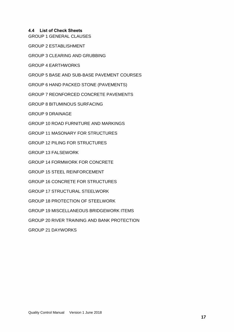
4.4 List of Check Sheets
GROUP 1 GENERAL CLAUSES
GROUP 2 ESTABLISHMENT
GROUP 3 CLEARING AND GRUBBING
GROUP 4 EARTHWORKS
GROUP 5 BASE AND SUB-BASE PAVEMENT COURSES
GROUP 6 HAND PACKED STONE (PAVEMENTS)
GROUP 7 REONFORCED CONCRETE PAVEMENTS
GROUP 8 BITUMINOUS SURFACING
GROUP 9 DRAINAGE
GROUP 10 ROAD FURNITURE AND MARKINGS
GROUP 11 MASONARY FOR STRUCTURES
GROUP 12 PILING FOR STRUCTURES
GROUP 13 FALSEWORK
GROUP 14 FORMWORK FOR CONCRETE
GROUP 15 STEEL REINFORCEMENT
GROUP 16 CONCRETE FOR STRUCTURES
GROUP 17 STRUCTURAL STEELWORK
GROUP 18 PROTECTION OF STEELWORK
GROUP 19 MISCELLANEOUS BRIDGEWORK ITEMS
GROUP 20 RIVER TRAINING AND BANK PROTECTION
GROUP 21 DAYWORKS
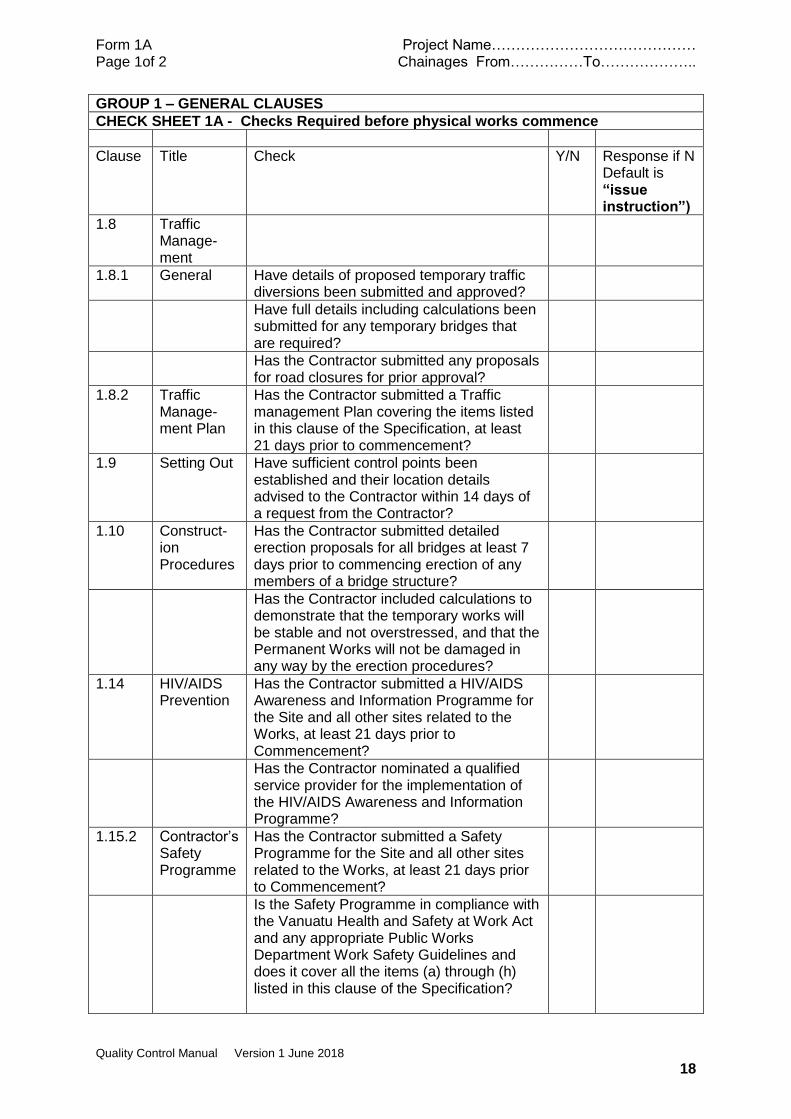
Form 1A Project Name…………………………………… Page 1of 2 Chainages From……………To………………..
Quality Control Manual Version 1 June 2018
18
GROUP 1 – GENERAL CLAUSES
CHECK SHEET 1A - Checks Required before physical works commence
Clause Title Check Y/N Response if N Default is “issue instruction”)
1.8 Traffic Manage-ment
1.8.1 General Have details of proposed temporary traffic diversions been submitted and approved?
Have full details including calculations been submitted for any temporary bridges that are required?
Has the Contractor submitted any proposals for road closures for prior approval?
1.8.2 Traffic Manage-ment Plan
Has the Contractor submitted a Traffic management Plan covering the items listed in this clause of the Specification, at least 21 days prior to commencement?
1.9 Setting Out Have sufficient control points been established and their location details advised to the Contractor within 14 days of a request from the Contractor?
1.10 Construct-ion Procedures
Has the Contractor submitted detailed erection proposals for all bridges at least 7 days prior to commencing erection of any members of a bridge structure?
Has the Contractor included calculations to demonstrate that the temporary works will be stable and not overstressed, and that the Permanent Works will not be damaged in any way by the erection procedures?
1.14 HIV/AIDS Prevention
Has the Contractor submitted a HIV/AIDS Awareness and Information Programme for the Site and all other sites related to the Works, at least 21 days prior to Commencement?
Has the Contractor nominated a qualified service provider for the implementation of the HIV/AIDS Awareness and Information Programme?
1.15.2 Contractor’s Safety Programme
Has the Contractor submitted a Safety Programme for the Site and all other sites related to the Works, at least 21 days prior to Commencement?
Is the Safety Programme in compliance with the Vanuatu Health and Safety at Work Act and any appropriate Public Works Department Work Safety Guidelines and does it cover all the items (a) through (h) listed in this clause of the Specification?

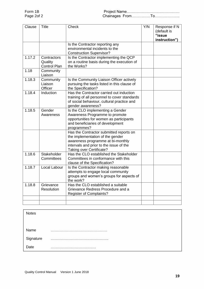
Form 1A Project Name…………………………………… Page 2of 2 Chainages From……………To………………..
Quality Control Manual Version 1 June 2018
19
Clause Title Check Y/N Response if N Default is “issue instruction”)
1.16.2 CEMP Has the Contractor submitted, within 28 days of signing the Contract and before commencing any work on Site, the Contractor’s Environmental Management Plan (CEMP) for the Site and all other sites related to the Works?
Does the CEMP cover all the requirements (a) through (m) of this clause of the Specification?
1.17.2 Contractors Quality Control Plan
Has the Contractor submitted a Quality Control Plan (QCP) for the Works at least twenty one (21) days prior to commencement?
Does the QCP cover all the items (a) through (g) of this clause of the Specification?
1.18 Community Liaison
1.18.1 General Has the Contractor visited all affected communities before commencing work on Site [in company with the Provincial Planner, a representative of the Provincial Council of Chiefs and the relevant Community Chief(s)] to explain construction activities?
1.18.2 Community Liaison Plan
Has the Contractor submitted a Community Liaison Plan (CLP) for the Works at least twenty one (21) days prior to commencement?
Does the CLP cover the items described in the 6 bullet points of this clause in the Specification?
1.18.3 Community Liaison Officer
Has the Contractor appointed a Community Liaison Officer?
1.18.6 Local labour Has the Contractor specifically nominated any foreign personnel and sub-contractors and does their residential status comply with the immigration regulations and the Labour Act?
Notes
Name ………………………………………
Signature ……………………………………….Date

Form 1B Project Name…………………………………… Page 1of 2 Chainages From……………To………………..
Quality Control Manual Version 1 June 2018
18
GROUP 1 – GENERAL CLAUSES
CHECK SHEET 1B - Checks Require During or After Physical Works
Clause Title Check Y/N Response if N (default is “issue instruction”)
1.8 Traffic Management
1.8.1 General Have sufficient and clearly delineated temporary signs, barriers and marker posts been erected to guide traffic through the working areas?
Are temporary signs illuminated at night?
Have all existing signs that are required to be removed temporarily or permanently being carefully stored?
Have all existing signs that were removed only temporarily been reinstated in a satisfactory manner?
Have all existing signs that are not required for re-use on the contract been delivered to the nearest PWD depot?
1.11 Loading Limits on Public Roads
Is the Contractor observing the loading limits of the Road Traffic Control Act?
1.14.2 HIV/AIDS Awareness programme
Is the Contractor implementing the awareness programme using an approved service provider and in compliance with all the requirements of this clause of the Specification?
1.15.2 Contractor’s Safety Programme
Is the Contractor implementing the approved Safety Programme and carrying out all the requirements of the second sub series (a) though (j) of this clause of the Specification?
1.16.2 CEMP Is the Contractor reviewing the CEMP monthly and updating as necessary?
Is the Contractor incorporating compliance with the CEMP into the conditions of any Sub-Contractor agreements?
Have all Contractor personnel undergone induction training into the application of the CEMP?
Is the Contractor maintaining a register of inducted personnel?
Is the Contractor recording non-conformances with the CEMP and providing a monthly summary?
Form 1B Project Name…………………………………… Page 2of 2 Chainages From……………To………………..
Quality Control Manual Version 1 June 2018
19
Clause Title Check Y/N Response if N (default is “issue instruction”)
Is the Contractor reporting any environmental incidents to the Construction Supervisor?
1.17.2 Contractors Quality Control Plan
Is the Contractor implementing the QCP on a routine basis during the execution of the Works?
1.18 Community Liaison
1.18.3 Community Liaison Officer
Is the Community Liaison Officer actively pursuing the tasks listed in this clause of the Specification?
1.18.4 Induction Has the Contractor carried out induction training of all personnel to cover standards of social behaviour, cultural practice and gender awareness?
1.18.5 Gender Awareness
Is the CLO implementing a Gender Awareness Programme to promote opportunities for women as participants and beneficiaries of development programmes?
Has the Contractor submitted reports on the implementation of the gender awareness programme at bi-monthly intervals and prior to the issue of the Taking over Certificate?
1.18.6 Stakeholder Committees
Has the CLO established the Stakeholder Committees in conformance with this clause of the Specification?
1.18.7 Local Labour Is the Contractor making reasonable attempts to engage local community groups and women’s groups for aspects of the work?
1.18.8 Grievance Resolution
Has the CLO established a suitable Grievance Redress Procedure and a Register of Complaints?
Notes
Name ………………………………………
Signature ……………………………………….
Date ………………………………

Form 1C Project Name…………………………………… Page 1of 1 Chainages From……………To………………..
Quality Control Manual Version 1 June 2018
20
GROUP 1 – GENERAL CLAUSES
CHECK SHEET 1C – Laboratory or Field Tests Required
clause Title Check Satisfactory Test results provided?
Not Relevant
Form 1D Project Name…………………………………… Page 2 of 2 Chainages From……………To………………..
Quality Control Manual Version 1 June 2018
21
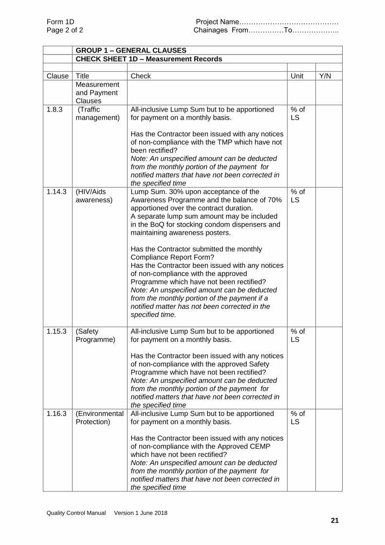
GROUP 1 – GENERAL CLAUSES
CHECK SHEET 1D – Measurement Records
Clause Title Check Unit Y/N
Measurement and Payment Clauses
1.8.3 (Traffic management)
All-inclusive Lump Sum but to be apportioned for payment on a monthly basis. Has the Contractor been issued with any notices of non-compliance with the TMP which have not been rectified? Note: An unspecified amount can be deducted from the monthly portion of the payment for notified matters that have not been corrected in the specified time
% of LS
1.14.3 (HIV/Aids awareness)
Lump Sum. 30% upon acceptance of the Awareness Programme and the balance of 70% apportioned over the contract duration. A separate lump sum amount may be included in the BoQ for stocking condom dispensers and maintaining awareness posters. Has the Contractor submitted the monthly Compliance Report Form? Has the Contractor been issued with any notices of non-compliance with the approved Programme which have not been rectified? Note: An unspecified amount can be deducted from the monthly portion of the payment if a notified matter has not been corrected in the specified time.
% of LS
1.15.3 (Safety Programme)
All-inclusive Lump Sum but to be apportioned for payment on a monthly basis. Has the Contractor been issued with any notices of non-compliance with the approved Safety Programme which have not been rectified? Note: An unspecified amount can be deducted from the monthly portion of the payment for notified matters that have not been corrected in the specified time
% of LS
1.16.3 (Environmental Protection)
All-inclusive Lump Sum but to be apportioned for payment on a monthly basis. Has the Contractor been issued with any notices of non-compliance with the Approved CEMP which have not been rectified? Note: An unspecified amount can be deducted from the monthly portion of the payment for notified matters that have not been corrected in the specified time
% of LS
Form 1D Project Name…………………………………… Page 2 of 2 Chainages From……………To………………..
Quality Control Manual Version 1 June 2018
22
Clause Title Check Unit Y/N
1.17.3 (Quality Control Plan)
All-inclusive Lump Sum but to be apportioned for payment on a monthly basis. Has the Contractor been issued with any notices of non-compliance with the Approved QCP which have not been rectified? Note: An unspecified amount can be deducted from the monthly portion of the payment for notified matters that have not been corrected in the specified time
% of LS
1.18.9 (Community Liaison)
All-inclusive Lump Sum but to be apportioned for payment on a monthly basis. Has the Contractor submitted the monthly summary of community liaison activities? Has the Contractor been issued with any notices of non-compliance with the required community liaison activities which have not been rectified? Note: An unspecified amount can be deducted from the monthly portion of the payment for notified matters that have not been corrected in the specified time
% of LS
Notes
Name ………………………………………
Signature ……………………………………….
Date ………………………………

Form 2A Project Name…………………………………… Page 1 of 1 Chainages From……………To………………..
Quality Control Manual Version 1 June 2018
23
GROUP 2 – ESTABLISHMENT
CHECK SHEET 2A - Checks Required before physical works commence
Clause Title Check Y/N Response if N Default is “issue instruction”)
NOT RELEVANT

Form 2B Project Name…………………………………… Page 1 of 1 Chainages From……………To………………..
Quality Control Manual Version 1 June 2018
24
GROUP 2 – ESTABLISHMENT
CHECK SHEET 2B - Checks Require During or After Physical Works
Clause Title Check Y/N Response if N (default is “issue instruction”)
2.1.1 General Do all accommodation units, offices, sheds and storage units meet the requirements of the relevant Health and Safety Regulations?
Are suitable arrangements in place for the collection and disposal of wastes?
2.2.2 Construction Supervisor’s Office
Is the office erected in compliance with the specified requirements and in the correct location within one month of contract award by letter of acceptance?
Has all the specified furniture and equipment been delivered?
2.3 Notice Boards
Have the required notice boards been erected on the site in conformance with the details on the drawings?
After completion, have the notice boards been removed and the sites where they were located left in a neat and tidy condition?
Notes
Name ………………………………………
Signature ……………………………………….
Date ………………………………

Form 2C Project Name…………………………………… Page 1 of 1 Chainages From……………To………………..
Quality Control Manual Version 1 June 2018
25
GROUP 2 – ESTABLISHMENT
CHECK SHEET 2C – Laboratory or Field Tests Required
clause Title Check Satisfactory Test results provided?
NOT RELEVANT
Form 2D Project Name…………………………………… Page 1 of 1 Chainages From……………To………………..
Quality Control Manual Version 1 June 2018
26
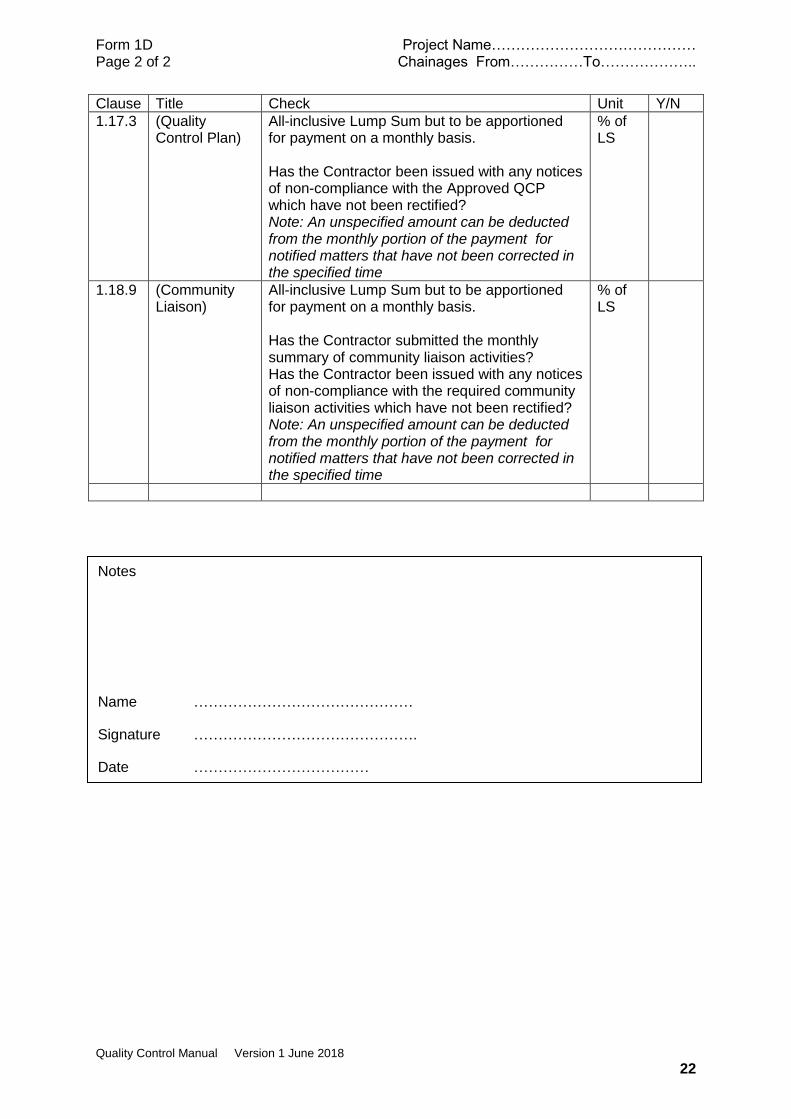
GROUP 2 – ESTABLISHMENT
CHECK SHEET 2D – Measurement Records
Clause Title Check Unit Y/N
2.1.2 Establishment Item in Bill
Is the Contractor established on the site in conformance with all the issues listed in this clause of the Specification to the satisfaction of the Construction Supervisor?
LS
2.1.4 Demobilisation Has demobilisation covering all items listed in this clause been completed to the satisfaction of the Construction Supervisor?
LS
Notes
Name ………………………………………
Signature ……………………………………….
Date ………………………………
Form 3A Project Name…………………………………… Page 1 of 2 Chainages From……………To………………..
Quality Control Manual Version 1 June 2018
27
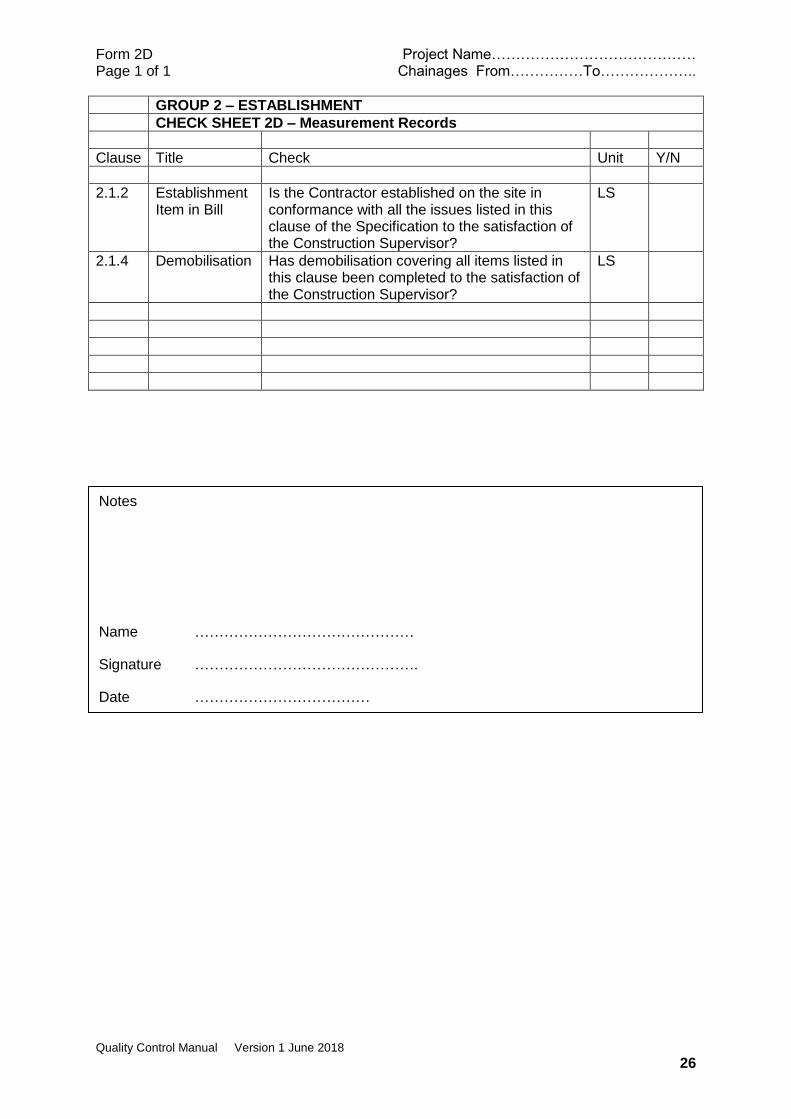
GROUP 3 - CLEARING AND GRUBBING
CHECK SHEET 3A - Checks Required before physical works commence
Clause Title Check Y/N Response if N Default is “issue instruction”)
3.1 Clearing and Grubbing
Is the ‘Area’ to be cleared covered by items (i) to (iv) of this sub-clause and/or clearly marked on the drawings? Note: It is suggested that the extent of the clearing limits be staked out
Issue instructions to designate the ‘Area’
Have any trees which are to be preserved been clearly indicated?
Mark trees to be preserved
Have any necessary instructions for Grubbing been issued? Note: the term ‘objectionable material’ is not defined. Suggest this is confined to material above ground level eg piles of trash, car wrecks. Objectionable material below ground level will be addressed in GROUP 4 EARTHWORKS
Issue any necessary instructions
Have items that are to be removed but which are not covered by the Pay Item for Clearing and Grubbing been measured? Note: this covers concrete headwalls, culverts, foundations
Carry out joint measure
3.1.1 Clearing Has the Contractor taken the necessary precautions to prevent damage to structures and other private or public property?
Issue instruction
3.1.2 Grubbing and Stripping of Topsoil
Has suitable ‘selected material’ been proposed and approved for the backfilling of holes from which obstructions are removed?
Instruct Contractor to submit proposal
Have any necessary instructions for the stockpiling and/or transport of topsoil been issued? Note: If drawings or the Supplementary Specification do not show where topsoil is to be a stockpiled an instruction may be required.
Issue instructions as necessary
3.2 Clearing of Stream Crossing Sites
Have necessary instructions for limits of work and felling of nearby trees been issued?
Issue instructions as necessary
3.3 Clearing of Existing Drainage Paths
Are any/all slips or slumps less than 5m3? Arrange joint measure of slips greater than 5m3
Form 3A Project Name…………………………………… Page 2 of 2 Chainages From……………To………………..
Quality Control Manual Version 1 June 2018
28
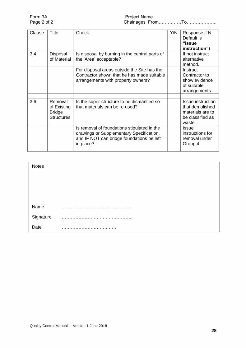
Clause Title Check Y/N Response if N Default is “issue instruction”)
3.4 Disposal of Material
Is disposal by burning in the central parts of the ’Area’ acceptable?
If not instruct alternative method.
For disposal areas outside the Site has the Contractor shown that he has made suitable arrangements with property owners?
Instruct Contractor to show evidence of suitable arrangements
3.6 Removal of Existing Bridge Structures
Is the super-structure to be dismantled so that materials can be re-used?
Issue instruction that demolished materials are to be classified as waste
Is removal of foundations stipulated in the drawings or Supplementary Specification, and IF NOT can bridge foundations be left in place?
Issue instructions for removal under Group 4
Notes
Name ………………………………………
Signature ……………………………………….
Date ………………………………
Form 3B Project Name…………………………………… Page 1 of 1 Chainages From……………To………………..
Quality Control Manual Version 1 June 2018
29
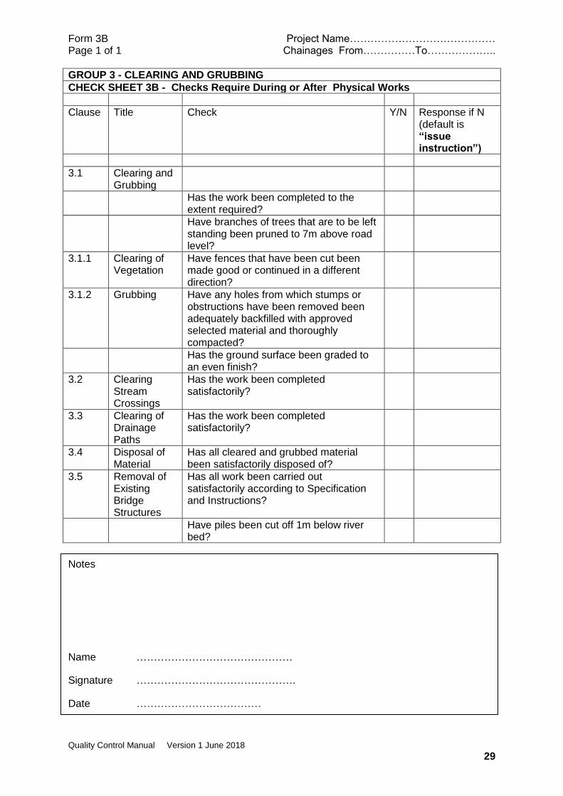
GROUP 3 - CLEARING AND GRUBBING
CHECK SHEET 3B - Checks Require During or After Physical Works
Clause Title Check Y/N Response if N (default is “issue instruction”)
3.1 Clearing and Grubbing
Has the work been completed to the extent required?
Have branches of trees that are to be left standing been pruned to 7m above road level?
3.1.1 Clearing of Vegetation
Have fences that have been cut been made good or continued in a different direction?
3.1.2 Grubbing Have any holes from which stumps or obstructions have been removed been adequately backfilled with approved selected material and thoroughly compacted?
Has the ground surface been graded to an even finish?
3.2 Clearing Stream Crossings
Has the work been completed satisfactorily?
3.3 Clearing of Drainage Paths
Has the work been completed satisfactorily?
3.4 Disposal of Material
Has all cleared and grubbed material been satisfactorily disposed of?
3.5 Removal of Existing Bridge Structures
Has all work been carried out satisfactorily according to Specification and Instructions?
Have piles been cut off 1m below river bed?
Notes
Name ………………………………………
Signature ……………………………………….
Date ………………………………
Form 3C Project Name…………………………………… Page 1 of 1 Chainages From……………To………………..
Quality Control Manual Version 1 June 2018
30
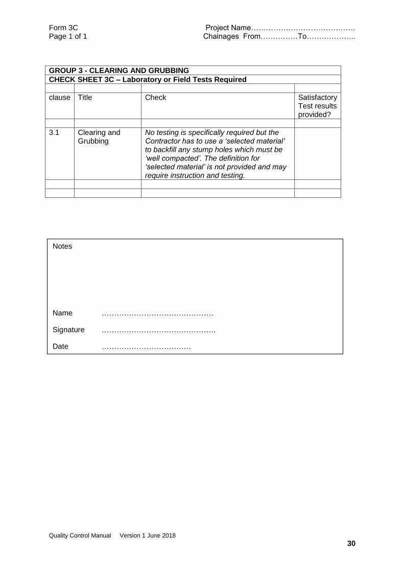
GROUP 3 - CLEARING AND GRUBBING
CHECK SHEET 3C – Laboratory or Field Tests Required
clause Title Check Satisfactory Test results provided?
3.1 Clearing and Grubbing
No testing is specifically required but the Contractor has to use a ‘selected material’ to backfill any stump holes which must be ‘well compacted’. The definition for ‘selected material’ is not provided and may require instruction and testing.
Notes
Name ………………………………………
Signature ……………………………………….
Date ………………………………

Form 3D Project Name…………………………………… Page 1 of 1 Chainages From……………To………………..
Quality Control Manual Version 1 June 2018
31
GROUP 3 - CLEARING AND GRUBBING
CHECK SHEET 3D – Measurement Records
Clause Title Check Unit Y/N
3.1 Clearing and Grubbing
Measurement records should be jointly agreed for Concrete Headwalls, Wing walls, Box culverts, Foundations which are to be removed and paid under Pay Item 4.5.4
m3
Measurement Records should be made for pipe culverts which are to be removed and stacked or transported according to item 7.6 (Group 7)
L
3.1.2 Measurement records should be jointly agreed for stump holes that are to be backfilled with selected material and paid under item 4.23
m3
3.3 Clearing drainage paths
Measurement Records should be jointly agreed for any slips and slumps greater than 5m3.
Slips and Slumps less than 5m3 are deemed to be included in the linear metre rate for clearing drainage paths
m3
3.5 Measurement and Payment
Clearing and Grubbing Note: Clearing, Grubbing and Topsoil removal to a depth of 150mm mm is paid under a single item. This item also covers stockpiling and/or transportation of topsoil.
hectare
Stream Crossings No.
Existing Drainage Paths m
3.6 Removal of Existing Bridge Structures
Should normally be a lump sum but may need separate measurement of foundations if instructions have been issued for removal of foundations under GROUP 4.
Notes
Name ………………………………………
Signature ……………………………………….
Date ………………………………

Form 4A Project Name…………………………………… Page 1 of 2 Chainages From……………To………………..
Quality Control Manual Version 1 June 2018
32
GROUP 4 - EARTHWORKS
CHECK SHEET 4A - Checks Required before physical works commence
Clause Title Check Y/N Response if N Default is “issue instruction”)
4.20.1 and 4.22.1
Measure-ment and Payment for General Excavation and Embank-ment
Has a topographical level survey been carried out after the completion of clearing and grubbing works under GROUP 3? Note: Sub-clause states “The cross sectional area to be used shall be that area bounded by the required finished sub grade, the required side slopes and the original ground level as it exists after clearing, grubbing and topsoil stripping operations have been completed”.
4.2.1 Dimensions Have any necessary instructions been issued regarding changes to dimensions, slopes or levels shown on drawings?
4.13 Use of Explosives
Has the Contractor given at least ten (10) days’ notice of any intention to excavate by blasting and supplied full details of the location and the methods he proposes to adopt?
This is a Hold Point
Has the blast management plan been submitted and approved Note: AS 2187.2 requires a blast management plan to be prepared and that no blasting is to be carried until the plan has been approved by a competent person. The plan must include, but is not limited to, risk management; a site safety plan; and blast design.
This is a Hold Point
4.14.4 and 4.15.4
Notice Has the Contractor submitted samples of the material proposed for use in the upper layer of embankment fill, at least 7 days prior to commencement of the work?
This is a Hold Point
4.18 Borrow Has the Contractor demonstrated that he has planned the earthworks operations to maximise the use of suitable materials obtained from excavations and to minimise the requirements for the use of Borrow? Note: This may require a detailed method statement including assessment of different types of materials and including a Mass/Haul diagram
Do not approve the use of Borrow until evidence of earthworks planning is produced
4.19.1 Fill to Structural Foundation - General
Has the Contractor submitted the proposed construction procedure for approval prior to commencement of the work?
This is a Hold Point
4.19.5.1
Fill to Bridge abutments-General
Has the Contractor submitted the proposed method for the backfill of bridge abutments for prior approval?
This is a Hold Point
Form 4A Project Name…………………………………… Page 2 of 2 Chainages From……………To………………..
Quality Control Manual Version 1 June 2018
33
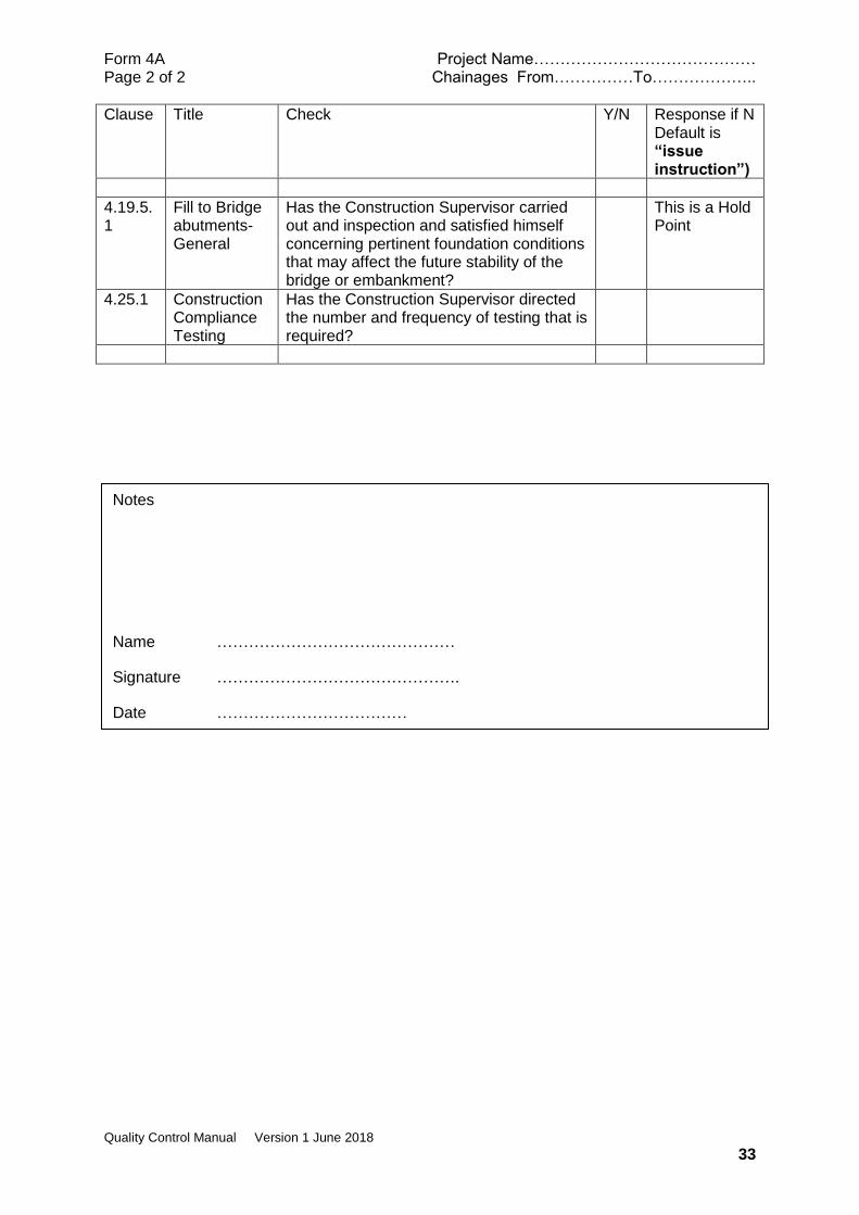
Clause Title Check Y/N Response if N Default is “issue instruction”)
4.19.5.1
Fill to Bridge abutments-General
Has the Construction Supervisor carried out and inspection and satisfied himself concerning pertinent foundation conditions that may affect the future stability of the bridge or embankment?
This is a Hold Point
4.25.1 Construction Compliance Testing
Has the Construction Supervisor directed the number and frequency of testing that is required?
Notes
Name ………………………………………
Signature ……………………………………….
Date ………………………………
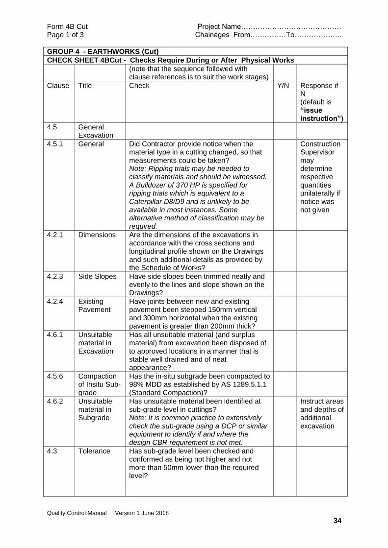
Form 4B Cut Project Name…………………………………… Page 1 of 3 Chainages From……………To………………..
Quality Control Manual Version 1 June 2018
34
GROUP 4 - EARTHWORKS (Cut)
CHECK SHEET 4BCut - Checks Require During or After Physical Works
(note that the sequence followed with clause references is to suit the work stages)
Clause Title Check Y/N Response if N (default is “issue instruction”)
4.5 General Excavation
4.5.1 General Did Contractor provide notice when the material type in a cutting changed, so that measurements could be taken? Note: Ripping trials may be needed to classify materials and should be witnessed. A Bulldozer of 370 HP is specified for ripping trials which is equivalent to a Caterpillar D8/D9 and is unlikely to be available in most instances. Some alternative method of classification may be required.
Construction Supervisor may determine respective quantities unilaterally if notice was not given
4.2.1 Dimensions Are the dimensions of the excavations in accordance with the cross sections and longitudinal profile shown on the Drawings and such additional details as provided by the Schedule of Works?
4.2.3 Side Slopes Have side slopes been trimmed neatly and evenly to the lines and slope shown on the Drawings?
4.2.4 Existing Pavement
Have joints between new and existing pavement been stepped 150mm vertical and 300mm horizontal when the existing pavement is greater than 200mm thick?
4.6.1 Unsuitable material in Excavation
Has all unsuitable material (and surplus material) from excavation been disposed of to approved locations in a manner that is stable well drained and of neat appearance?
4.5.6 Compaction of Insitu Sub-grade
Has the in-situ subgrade been compacted to 98% MDD as established by AS 1289.5.1.1 (Standard Compaction)?
4.6.2 Unsuitable material in Subgrade
Has unsuitable material been identified at sub-grade level in cuttings? Note: It is common practice to extensively check the sub-grade using a DCP or similar equipment to identify if and where the design CBR requirement is not met.
Instruct areas and depths of additional excavation
4.3 Tolerance Has sub-grade level been checked and conformed as being not higher and not more than 50mm lower than the required level?
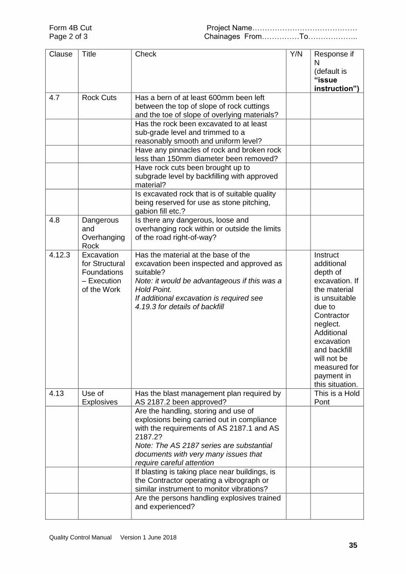
Form 4B Cut Project Name…………………………………… Page 2 of 3 Chainages From……………To………………..
Quality Control Manual Version 1 June 2018
35
Clause Title Check Y/N Response if N (default is “issue instruction”)
4.7 Rock Cuts Has a bern of at least 600mm been left between the top of slope of rock cuttings and the toe of slope of overlying materials?
Has the rock been excavated to at least sub-grade level and trimmed to a reasonably smooth and uniform level?
Have any pinnacles of rock and broken rock less than 150mm diameter been removed?
Have rock cuts been brought up to subgrade level by backfilling with approved material?
Is excavated rock that is of suitable quality being reserved for use as stone pitching, gabion fill etc.?
4.8 Dangerous and Overhanging Rock
Is there any dangerous, loose and overhanging rock within or outside the limits of the road right-of-way?
4.12.3 Excavation for Structural Foundations – Execution of the Work
Has the material at the base of the excavation been inspected and approved as suitable? Note: it would be advantageous if this was a Hold Point. If additional excavation is required see 4.19.3 for details of backfill
Instruct additional depth of excavation. If the material is unsuitable due to Contractor neglect. Additional excavation and backfill will not be measured for payment in this situation.
4.13 Use of Explosives
Has the blast management plan required by AS 2187.2 been approved?
This is a Hold Pont
Are the handling, storing and use of explosions being carried out in compliance with the requirements of AS 2187.1 and AS 2187.2? Note: The AS 2187 series are substantial documents with very many issues that require careful attention
If blasting is taking place near buildings, is the Contractor operating a vibrograph or similar instrument to monitor vibrations?
Are the persons handling explosives trained and experienced?
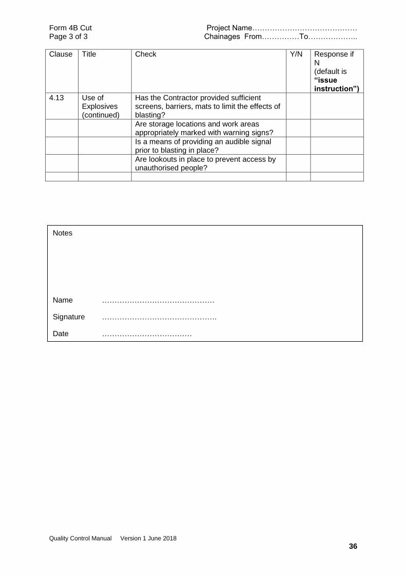
Form 4B Cut Project Name…………………………………… Page 3 of 3 Chainages From……………To………………..
Quality Control Manual Version 1 June 2018
36
Clause Title Check Y/N Response if N (default is “issue instruction”)
4.13 Use of Explosives (continued)
Has the Contractor provided sufficient screens, barriers, mats to limit the effects of blasting?
Are storage locations and work areas appropriately marked with warning signs?
Is a means of providing an audible signal prior to blasting in place?
Are lookouts in place to prevent access by unauthorised people?
Notes
Name ………………………………………
Signature ……………………………………….
Date ………………………………
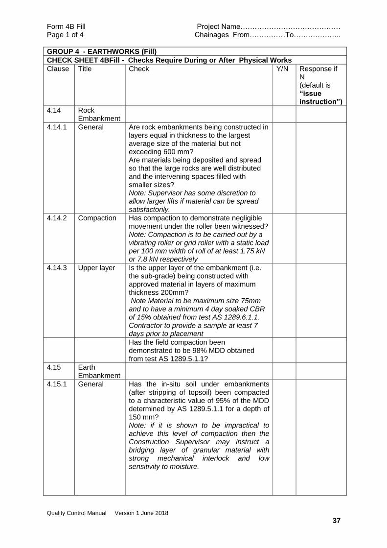
Form 4B Fill Project Name…………………………………… Page 1 of 4 Chainages From……………To………………..
Quality Control Manual Version 1 June 2018
37
GROUP 4 - EARTHWORKS (Fill)
CHECK SHEET 4BFill - Checks Require During or After Physical Works
Clause Title Check Y/N Response if N (default is “issue instruction”)
4.14 Rock Embankment
4.14.1 General Are rock embankments being constructed in layers equal in thickness to the largest average size of the material but not exceeding 600 mm? Are materials being deposited and spread so that the large rocks are well distributed and the intervening spaces filled with smaller sizes? Note: Supervisor has some discretion to allow larger lifts if material can be spread satisfactorily.
4.14.2 Compaction Has compaction to demonstrate negligible movement under the roller been witnessed? Note: Compaction is to be carried out by a vibrating roller or grid roller with a static load per 100 mm width of roll of at least 1.75 kN or 7.8 kN respectively
4.14.3 Upper layer Is the upper layer of the embankment (i.e. the sub-grade) being constructed with approved material in layers of maximum thickness 200mm? Note Material to be maximum size 75mm and to have a minimum 4 day soaked CBR of 15% obtained from test AS 1289.6.1.1. Contractor to provide a sample at least 7 days prior to placement
Has the field compaction been demonstrated to be 98% MDD obtained from test AS 1289.5.1.1?
4.15 Earth Embankment
4.15.1 General Has the in-situ soil under embankments (after stripping of topsoil) been compacted to a characteristic value of 95% of the MDD determined by AS 1289.5.1.1 for a depth of 150 mm? Note: if it is shown to be impractical to achieve this level of compaction then the Construction Supervisor may instruct a bridging layer of granular material with strong mechanical interlock and low sensitivity to moisture.
Form 4B Fill Project Name…………………………………… Page 3 of 4 Chainages From……………To………………..
Quality Control Manual Version 1 June 2018
38
Clause Title Check Y/N Response if N (default is “issue instruction”)
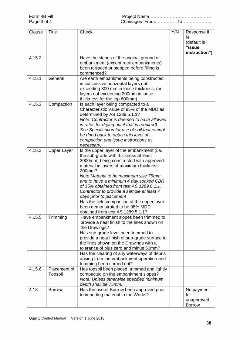
4.15.2 Have the slopes of the original ground or embankment (except rock embankments) been terraced or stepped before filling is commenced?
4.15.1 General Are earth embankments being constructed in successive horizontal layers not exceeding 300 mm in loose thickness, (or layers not exceeding 200mm in loose thickness for the top 600mm)
4.15.2 Compaction Is each layer being compacted to a Characteristic Value of 95% of the MDD as determined by AS 1289.5.1.1? Note: Contractor is deemed to have allowed in rates for drying out if that is required) See Specification for use of soil that cannot be dried back to obtain this level of compaction and issue instructions as necessary.
4.15.3 Upper Layer Is the upper layer of the embankment (i.e. the sub-grade with thickness at least 3000mm) being constructed with approved material in layers of maximum thickness 200mm? Note Material to be maximum size 75mm and to have a minimum 4 day soaked CBR of 15% obtained from test AS 1289.6.1.1. Contractor to provide a sample at least 7 days prior to placement
Has the field compaction of the upper layer been demonstrated to be 98% MDD obtained from test AS 1289.5.1.1?
4.15.5 Trimming Have embankment slopes been trimmed to provide a neat finish to the lines shown on the Drawings?
Has sub-grade level been trimmed to provide a neat finish of sub-grade surface to the lines shown on the Drawings with a tolerance of plus zero and minus 50mm?
Has the clearing of any waterways of debris arising from the embankment operation and trimming been carried out?
4.15.6 Placement of Topsoil
Has topsoil been placed, trimmed and lightly compacted on the embankment slopes? Note: Unless otherwise specified minimum depth shall be 75mm.
4.18 Borrow Has the use of Borrow been approved prior to importing material to the Works?
No payment for unapproved Borrow

Form 4B Fill Project Name…………………………………… Page 3 of 4 Chainages From……………To………………..
Quality Control Manual Version 1 June 2018
39
Clause Title Check Y/N Response if N (default is “issue instruction”)
Are Borrow pits being excavated so that they will drain?
Have Borrow Pits been staked out and cross-sectioned prior to commencement of excavation?
No excavation allowed until pit staked out
Have side slopes of Borrow Pits been trimmed and dressed to suitable slopes?
4.19 Fill for Structural Foundations
4.19.1 General Has the proposed construction method been submitted and approved?
Do not allow work to commence
4.19.2 Placing fill Has fill of sub-base standard been placed in maximum 200mm layers and compacted to 95%MDD determined from AS 1289.5.1.1 (Standard Compaction)
4.19.3 Backfill below foundation
Does the backfill to any over excavation of a structural foundation consist of lean mix concrete or sub-base quality material?
Reject other materials
If Sub-base material has it been placed in maximum 200mm layers and compacted to 95% MDD determined from AS 1289.5.1.1 (Standard Compaction)
4.19.4 Backfill to Excavation
Has the backfill of the excavation after installation of the foundation been carried out using an approved material?
Has the backfill been placed in even layers not exceeding 300 mm thick and compacted to at least 95% MDD in accordance with AS 1289.5.1.1. (standard compaction)
4.19.5 Fill to bridge abutments
Has the Contractor received approval for the proposed method of carrying out the work?
No work to commence until consent given to method
Does backfill material conform to sub-base requirements? Note: Compaction requirement for backfill is not stipulated but needs to be carried out to a high standard as settlement behind abutments is a common problem. 100% MDD from Modified Compaction would be a good standard

Form 4B Fill Project Name…………………………………… Page 3 of 4 Chainages From……………To………………..
Quality Control Manual Version 1 June 2018
40
Clause Title Check Y/N Response if N (default is “issue instruction”)
4.19.5 Fill to bridge abutments (continued)
Has a drainage layer been constructed according to the drawings or otherwise as described in the Specification?
Notes
Name ………………………………………
Signature ……………………………………….
Date ………………………………

Form 4C Project Name…………………………………… Page 1 of 1 Chainages From……………To………………..
Quality Control Manual Version 1 June 2018
41
GROUP 4 - EARTHWORKS
CHECK SHEET 4C – Laboratory or Field Tests Required
clause Title Check Y/N Satisfactory Test results provided?
4.5.6 Compaction of In-situ Subgrade in Excavation
Subgrade to be compacted to 98% MDD obtained under AS 1289.5.1.1 (Standard Compaction)
4.6.2 Unsuitable Material in Sub-grade
Testing is required to demonstrate that sub-grade has the minimum design CBR value, commonly using a DCP. Contractor testing should be witnessed or testing should be carried out independently
If unsuitable material is replaced with approved selected material then retesting for compaction will be required.
4.14.3 Rock Embankment – Upper Layer
Material for upper layer (at least the top 300mm ) to be maximum size 75mm and demonstrate 4 day soaked CBR of 15% (Test AS 1289.6.1.1)
Field compaction to be 98% MDD obtained from test AS 1289.5.1.1 (Standard Compaction)
4.15.1 Earth Embankments-General
Insitu soil underlying embankments to be compacted to 95% MDD obtained from AS 1289.5.1.1 (Standard Compaction)
4.15.2 Compaction Each layer of embankment soil to be compacted to 95% MDD obtained from AS 1289.5.1.1 (Standard Compaction)
4.15.3 Upper layer Material for upper layer (at least the top 300mm) to be maximum size 75mm and demonstrate 4 day soaked CBR of 15% (Test AS 1289.6.1.1)
Field compaction of upper layer to be 98% MDD obtained from test AS 1289.5.1.1 (Standard Compaction)
4.19.2 Fill below structural foundations
Field compaction of fill to be 95% MDD obtained from test AS 1289.5.1.1 (Standard Compaction)
4.19.3 Backfill below structural foundations
Field compaction of backfill (sub-base quality material) to be 95% MDD obtained from test AS 1289.5.1.1 (Standard Compaction)
4.19.4 Backfill to excavation for structural foundations
Field compaction of fill to be 95% MDD obtained from test AS 1289.5.1.1 (Standard Compaction)
Notes
Name ………………………………………
Signature ………………………………………. Date …………..
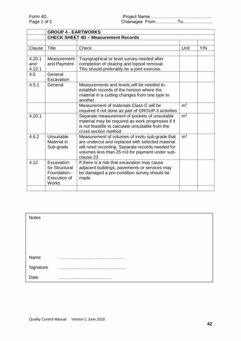
Form 4D Project Name…………………………………… Page 1 of 1 Chainages From……………To………………..
Quality Control Manual Version 1 June 2018
42
GROUP 4 - EARTWORKS
CHECK SHEET 4D – Measurement Records
Clause Title Check Unit Y/N
4.20.1 and 4.22.1
Measurement and Payment
Topographical or level survey needed after completion of clearing and topsoil removal. This should preferably be a joint exercise.
4.5 General Excavation
4.5.1 General Measurements and levels will be needed to establish records of the horizon where the material in a cutting changes from one type to another.
Measurement of materials Class C will be required if not done as part of GROUP 3 activities
m3
4.20.1 Separate measurement of pockets of unsuitable material may be required as work progresses if it is not feasible to calculate unsuitable from the cross section method
m3
4.6.2 Unsuitable Material in Sub-grade
Measurement of volumes of insitu sub-grade that are undercut and replaced with selected material will need recording. Separate records needed for volumes less than 25 m3 for payment under sub-clause 23
m3
4.12 Excavation for Structural Foundation -Execution of Works
If there is a risk that excavation may cause adjacent buildings, pavements or services may be damaged a pre-condition survey should be made.
Notes
Name ………………………………………
Signature ……………………………………….
Date ………………………………
Form 5A Project Name…………………………………… Page 1 of 1 Chainages From……………To………………..
Quality Control Manual Version 1 June 2018
43
GROUP 5 - BASE AND SUB-BASE PAVEMENT COURSES
CHECK SHEET 5A - Checks Required before physical works commence
Clause Title Check Y/N Response if N Default is “issue instruction”)
5.2 Materials
5.2.1 Material Source Assessment
Has the Contractor submitted the material source assessment report at least 10 days prior to planned delivery of material to stockpile or pavement?
Delivery should not commence
Does the assessment include an investigation of geological site characteristics and source material properties, and describe the extraction and production operations and plant capacity to process the material?
Instruct that the report to be amended
Has the material source been classified into one of the material groups nominated in the Specification and does the assessment show that the material meets all the requirements without addition of imported material?
Is the material classification for Base and Sub-base shown on the Drawings or Supplementary Specification? Note: If not indicated the default requirement is Base to be Class 2.1 and Sub-base to be Class 3.2
5.2.3 Coronous Material
If it is proposed to use coronous material, has a source been approved?
Has the method of selection and processing been approved prior to full scale production?
Has the Contractor demonstrated that the material complies with all the specified requirements?
5.2.4 Cinder or Scoria
Has the Contractor proposed to use scoria and has a source been approved?
Has the method of selection and processing been approved prior to full scale production?
Has the Contractor demonstrated that the material complies with all the specified requirements?
5.3.2 Stockpile Are lot sizes, number and frequency of tests detailed in a Supplementary Specification?
Construction Supervisor to issue directive
Notes
Name ………………………………………
Signature ………………………………………. Date …………………………

Form 5B Project Name…………………………………… Page 1 of 3 Chainages From……………To………………..
Quality Control Manual Version 1 June 2018
44
GROUP 5 - BASE AND SUB-BASE PAVEMENT COURSES
CHECK SHEET 5B - Checks Require During or After Physical Works
Clause Title Check Y/N Response if N (default is “issue instruction”)
5.2 Materials
5.2.2 Material Types
Has imported material been added to a source material?
Further testing will be required
5.3.2 Stockpile Are stockpiles located on clear, even, firm, and well drained ground and well indicated as to content?
Are separate stockpiles at least 2 metres apart?
Are lot sizes, number and frequency of tests detailed in a Supplementary Specification?
Construction Supervisor to issue directive
5.4 Construct-ion
5.4.1 Mainten-ance of Sub-grade and Pavement Layers
Has the Contractor adequately maintained the condition of the sub-grade or pavement layer upon which pavement material is to be placed?
Instruct reinstatement measures (Contractor’s expense)
5.4.2 Overlay of Existing Formation
If material is to be added to an existing pavement has the top been suitably scarified?
Instruct depth to be scarified
Is the total depth of scarified and added material within the specified layer thickness limits? Note: minimum 75 mm to maximum 250mm
5.4.4 Moisture Content
Is the moisture content of the pavement material to be compacted at or near to the Optimum Moisture Content?
Add water or dry back before compaction
5.4.5 Surface Finish
Does the final unbound pavement layer have a uniform surface free from loose or segregated and contaminated areas with course particle slightly exposed? Note: if coronous material is being used the exposure of course particles may not be practicable
Instruct additional brooming, watering and rolling or rip and rework as may be appropriate
5.4.6 Application of Prime Coat
Have the levels, compaction and surface finish of the base course surface been approved?
Bituminous surfacing cannot commence
Form 5B Project Name…………………………………… Page 2 of 3 Chainages From……………To………………..
Quality Control Manual Version 1 June 2018
45
Clause Title Check Y/N Response if N (default is “issue instruction”)
5.5 Product Standards
5.5.1 Horizontal Alignment
Is the location of any point on the pavement within ±50mm of the corresponding point in the contract documents? Note: An unconstrained edge (no kerb, channel or edge strip) will need to be overbuilt slightly to ensure that compaction can be achieved over the carriageway design width. In this circumstance the plus tolerance should be interpreted pragmatically.
5.5.2 Surface Finish
Do the vertical alignment tolerances comply with the specified requirements? Note:
Pavement
Course
Primary
Tolerance
(mm)
3m Straight Edge
Deviation Limit
(mm)
Base
Course
Sub Base
Course
+ 15
+ 15
5
8
Is the crossfall within 0.5% of the specified value? Note: Crossfall is measured within the boundaries of a cross-section element which has a constant fall between any two points more than 2 metres apart, except for portions of cross-sections designed with lesser width, for which sections the crossfall shall be measured between the extreme edges of the section; measurement is transverse to the centre line
Does the surface evenness meet the specified requirements?
5.5.2 Compaction Have pavements using Type 1 material been compacted to a Characteristic value of 98% MDD obtained from AS 1289.5.2.1 (Modified Compaction)
Have pavements using any other material, including coronous, cinder and scoria material been compacted to a Characteristic value of 98% MDD obtained from AS 1289.5.2.1 (Modified Compaction)
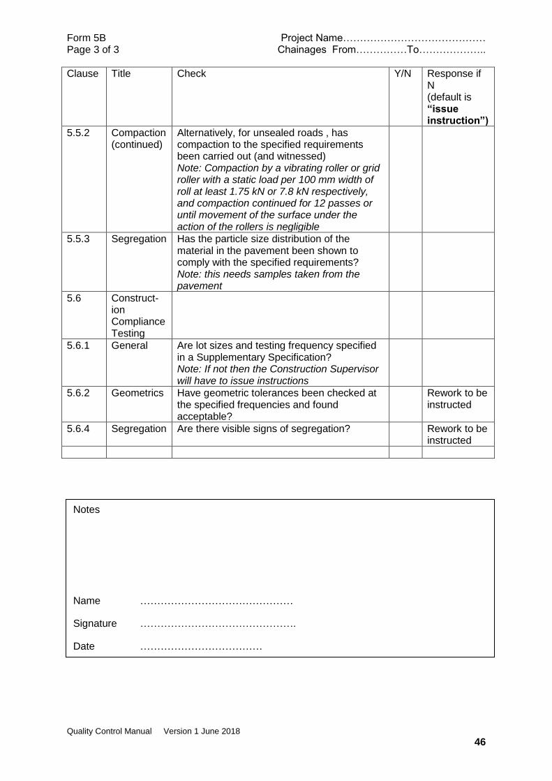
Form 5B Project Name…………………………………… Page 3 of 3 Chainages From……………To………………..
Quality Control Manual Version 1 June 2018
46
Clause Title Check Y/N Response if N (default is “issue instruction”)
5.5.2 Compaction (continued)
Alternatively, for unsealed roads , has compaction to the specified requirements been carried out (and witnessed) Note: Compaction by a vibrating roller or grid roller with a static load per 100 mm width of roll at least 1.75 kN or 7.8 kN respectively, and compaction continued for 12 passes or until movement of the surface under the action of the rollers is negligible
5.5.3 Segregation Has the particle size distribution of the material in the pavement been shown to comply with the specified requirements? Note: this needs samples taken from the pavement
5.6 Construct-ion Compliance Testing
5.6.1 General Are lot sizes and testing frequency specified in a Supplementary Specification? Note: If not then the Construction Supervisor will have to issue instructions
5.6.2 Geometrics Have geometric tolerances been checked at the specified frequencies and found acceptable?
Rework to be instructed
5.6.4 Segregation Are there visible signs of segregation? Rework to be instructed
Notes
Name ………………………………………
Signature ……………………………………….
Date ………………………………
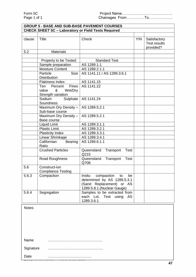
Form 5C Project Name…………………………………… Page 1 of 1 Chainages From……………To………………..
Quality Control Manual Version 1 June 2018
47
GROUP 5 - BASE AND SUB-BASE PAVEMENT COURSES
CHECK SHEET 5C – Laboratory or Field Tests Required
clause Title Check Y/N Satisfactory Test results provided?
5.2 Materials
Property to be Tested Standard Test
Sample preparation AS 1289.1.1
Moisture Content AS 1289.2.1.1
Particle Size Distribution
AS 1141.11 / AS 1289.3.6.1
Flakiness Index AS 1141.15
Ten Percent Fines value & Wet/Dry Strength variation
AS 1141.22
Sodium Sulphate Soundness
AS 1141.24
Maximum Dry Density – Sub-base course
AS 1289.5.2.1
Maximum Dry Density – Base course
AS 1289.5.2.1
Liquid Limit AS 1289.3.1.1
Plastic Limit AS 1289.3.2.1
Plasticity Index AS 1289.3.3.1
Linear Shrinkage AS 1289.3.4.1
Californian Bearing Ratio
AS 1289.6.1.1
Crushed Particles Queensland Transport Test Q215
Road Roughness Queensland Transport Test Q708
5.6 Construct-ion Compliance Testing
5.6.3 Compaction Insitu compaction to be determined by AS 1289.5.3.1 (Sand Replacement) or AS 1289.5.8.1.(Nuclear Gauge)
5.6.4 Segregation Samples to be extracted from each Lot. Test using AS 1289.3.6.1
Notes
Name ………………………………………
Signature ……………………………………….
Date ………………………………
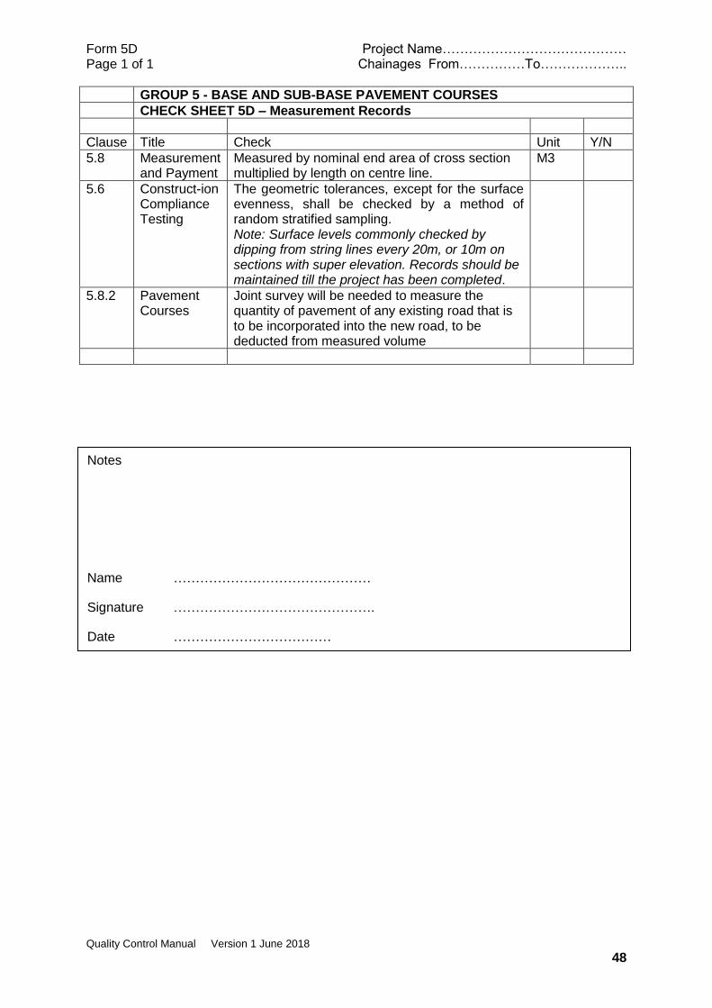
Form 5D Project Name…………………………………… Page 1 of 1 Chainages From……………To………………..
Quality Control Manual Version 1 June 2018
48
GROUP 5 - BASE AND SUB-BASE PAVEMENT COURSES
CHECK SHEET 5D – Measurement Records
Clause Title Check Unit Y/N
5.8 Measurement and Payment
Measured by nominal end area of cross section multiplied by length on centre line.
M3
5.6 Construct-ion Compliance Testing
The geometric tolerances, except for the surface evenness, shall be checked by a method of random stratified sampling. Note: Surface levels commonly checked by dipping from string lines every 20m, or 10m on sections with super elevation. Records should be maintained till the project has been completed.
5.8.2 Pavement Courses
Joint survey will be needed to measure the quantity of pavement of any existing road that is to be incorporated into the new road, to be deducted from measured volume
Notes
Name ………………………………………
Signature ……………………………………….
Date ………………………………

Form 6A Project Name…………………………………… Page 1 of 2 Chainages From……………To………………..
Quality Control Manual Version 1 June 2018
49
GROUP 6 – HAND PACKED STONE PAVEMENT
CHECK SHEET 6A - Checks Required before physical works commence
Clause Title Check Y/N Response if N Default is “issue instruction”)
6.2 Materials
6.2.1 Stone Has the parent rock been approved? Note:
• Uniaxial Compressive Strength >75MPa
• Los Angeles Abrasion <25%
• Sodium Sulphate Soundness <10% loss
6.2.2 Bedding Material
Has the bedding material been approved?
6.2.3 Joint filling and Binding Material
Has the joint filling material been approved? Note: material shall be non-plastic, angular, well graded, crushed stone or natural sand which is free from deleterious material and shall have:
• Fineness Modulus of sand fraction shall not be less than 1.80.(FM obtained from the sum of the cumulative percentages of aggregate retained on each of the standard sieves ranging from 9.5 mm to 150 micron and dividing this sum by 100)
• Fraction passing 75 micron sieve shall not exceed 10%
Recommended target grading
Sieve
Designation
Percentage by
weight passing
square mesh sieves
25 mm 100
10 mm 60-100
2.00 mm 40-70
0.425 mm 25-45
0.075 mm 0-10
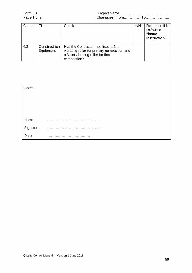
Form 6B Project Name…………………………………… Page 1 of 2 Chainages From……………To………………..
Quality Control Manual Version 1 June 2018
50
Clause Title Check Y/N Response if N Default is “issue instruction”)
6.3 Construct-ion Equipment
Has the Contractor mobilised a 1 ton vibrating roller for primary compaction and a 3 ton vibrating roller for final compaction?
Notes
Name ………………………………………
Signature ……………………………………….
Date ………………………………

Form 6B Project Name…………………………………… Page 1 of 2 Chainages From……………To………………..
Quality Control Manual Version 1 June 2018
51
GROUP 6 – HAND PACKED STONE PAVEMENT
CHECK SHEET 6B - Checks Require During or After Physical Works
Clause Title Check Y/N Response if N (default is “issue instruction”)
6.2 Materials Has the parent rock providing the source of stone been approved?
Are stones free from vegetation, soft particles and excess clay or any other substance, which is considered deleterious?
Are individual large stones approximately 100 to 150mm in size and roughly cubic in shape with uniform texture? Note: Ratios between dimensions of each stone shall be in range of 0.7 to 1.
6.2.2 Bedding Material
Is the bedding material clean sharp sand or quarry-crushed-dust free from clay coating, organic debris and other deleterious materials?
6.2.3 Joint filling and Blinding Material
Is the material used to fill the voids between the large and small wedging stones acceptable?
6.4 Construct-ion Method
6.4.1 Preparation of the Foundation
Have sufficient setting out pins, pegs and string lines been established to ensure that the final shape of each pavement layer confirms with the Drawings?
Is the Sub-base free from deformations, ruts, soft spots or other defects?
Surface to be re-scarified and sufficient new material added to attain the correct shape.
6.4.2 Shoulder Construct-ion
Are the shoulders being constructed in advance to the thickness indicated in the Drawings and are arrangements for drainage of the roadbase layer (through the shoulder) being incorporated?
6.4.3 Bedding Layer
Is the bedding layer being constructed with approved material to a compacted thickness of 50-60mm?
Is compaction being varied out with 0.8 – 1 ton rollers operating in a direction parallel to the centre line and working from the edge towards the centre?
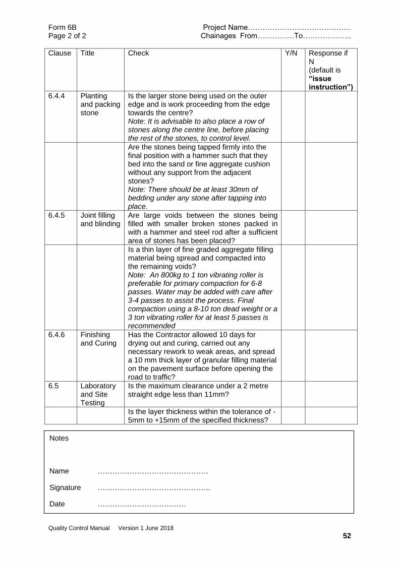
Form 6B Project Name…………………………………… Page 2 of 2 Chainages From……………To………………..
Quality Control Manual Version 1 June 2018
52
Clause Title Check Y/N Response if N (default is “issue instruction”)
6.4.4 Planting and packing stone
Is the larger stone being used on the outer edge and is work proceeding from the edge towards the centre? Note: It is advisable to also place a row of stones along the centre line, before placing the rest of the stones, to control level.
Are the stones being tapped firmly into the final position with a hammer such that they bed into the sand or fine aggregate cushion without any support from the adjacent stones? Note: There should be at least 30mm of bedding under any stone after tapping into place.
6.4.5 Joint filling and blinding
Are large voids between the stones being filled with smaller broken stones packed in with a hammer and steel rod after a sufficient area of stones has been placed?
Is a thin layer of fine graded aggregate filling material being spread and compacted into the remaining voids? Note: An 800kg to 1 ton vibrating roller is preferable for primary compaction for 6-8 passes. Water may be added with care after 3-4 passes to assist the process. Final compaction using a 8-10 ton dead weight or a 3 ton vibrating roller for at least 5 passes is recommended
6.4.6 Finishing and Curing
Has the Contractor allowed 10 days for drying out and curing, carried out any necessary rework to weak areas, and spread a 10 mm thick layer of granular filling material on the pavement surface before opening the road to traffic?
6.5 Laboratory and Site Testing
Is the maximum clearance under a 2 metre straight edge less than 11mm?
Is the layer thickness within the tolerance of -5mm to +15mm of the specified thickness?
Notes
Name ………………………………………
Signature ……………………………………….
Date ………………………………
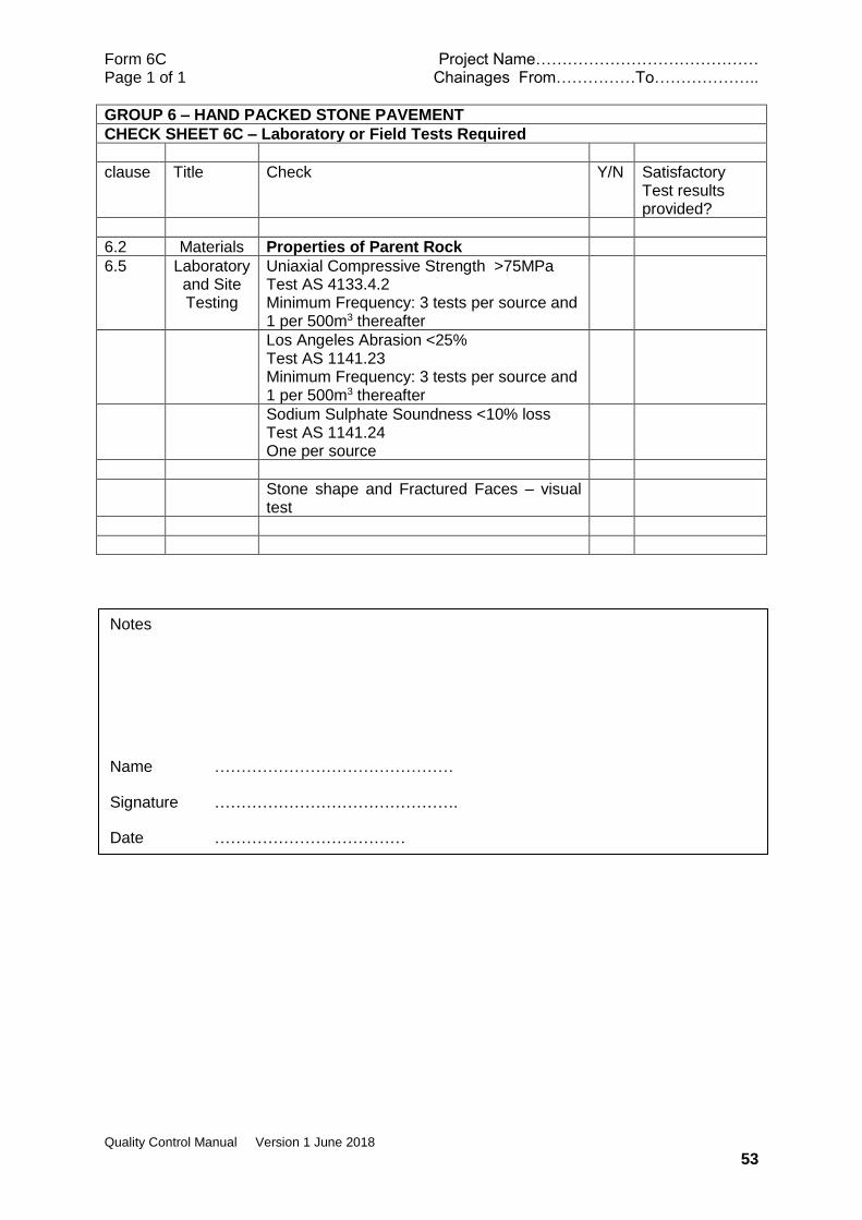
Form 6C Project Name…………………………………… Page 1 of 1 Chainages From……………To………………..
Quality Control Manual Version 1 June 2018
53
GROUP 6 – HAND PACKED STONE PAVEMENT
CHECK SHEET 6C – Laboratory or Field Tests Required
clause Title Check Y/N Satisfactory Test results provided?
6.2 Materials Properties of Parent Rock
6.5 Laboratory and Site Testing
Uniaxial Compressive Strength >75MPa Test AS 4133.4.2 Minimum Frequency: 3 tests per source and 1 per 500m3 thereafter
Los Angeles Abrasion <25% Test AS 1141.23 Minimum Frequency: 3 tests per source and 1 per 500m3 thereafter
Sodium Sulphate Soundness <10% loss Test AS 1141.24 One per source
Stone shape and Fractured Faces – visual test
Notes
Name ………………………………………
Signature ……………………………………….
Date ………………………………

Form 6D Project Name…………………………………… Page 1 of 1 Chainages From……………To………………..
Quality Control Manual Version 1 June 2018
54
GROUP 6 – HAND PACKED STONE PAVEMENT
CHECK SHEET 6D – Measurement Records
Clause Title Check Unit Y/N
6.6 Measurement and Payment
All in rate m2
Notes
Name ………………………………………
Signature ……………………………………….
Date ………………………………

Form 7A Project Name…………………………………… Page 1 of 1 Chainages From……………To………………..
Quality Control Manual Version 1 June 2018
55
GROUP 7 – REINFORCED CONCRETE PAVEMENT
CHECK SHEET 7A - Checks Required before physical works commence
Clause Title Check Y/N Response if N Default is “issue instruction”)
7.2 Materials
7.2.1 Reinforce-ment
Use Check Sheet for GROUP15
7.2.2 Concrete Use Check Sheet for GROUP 16
Notes
Name ………………………………………
Signature ……………………………………….
Date ………………………………
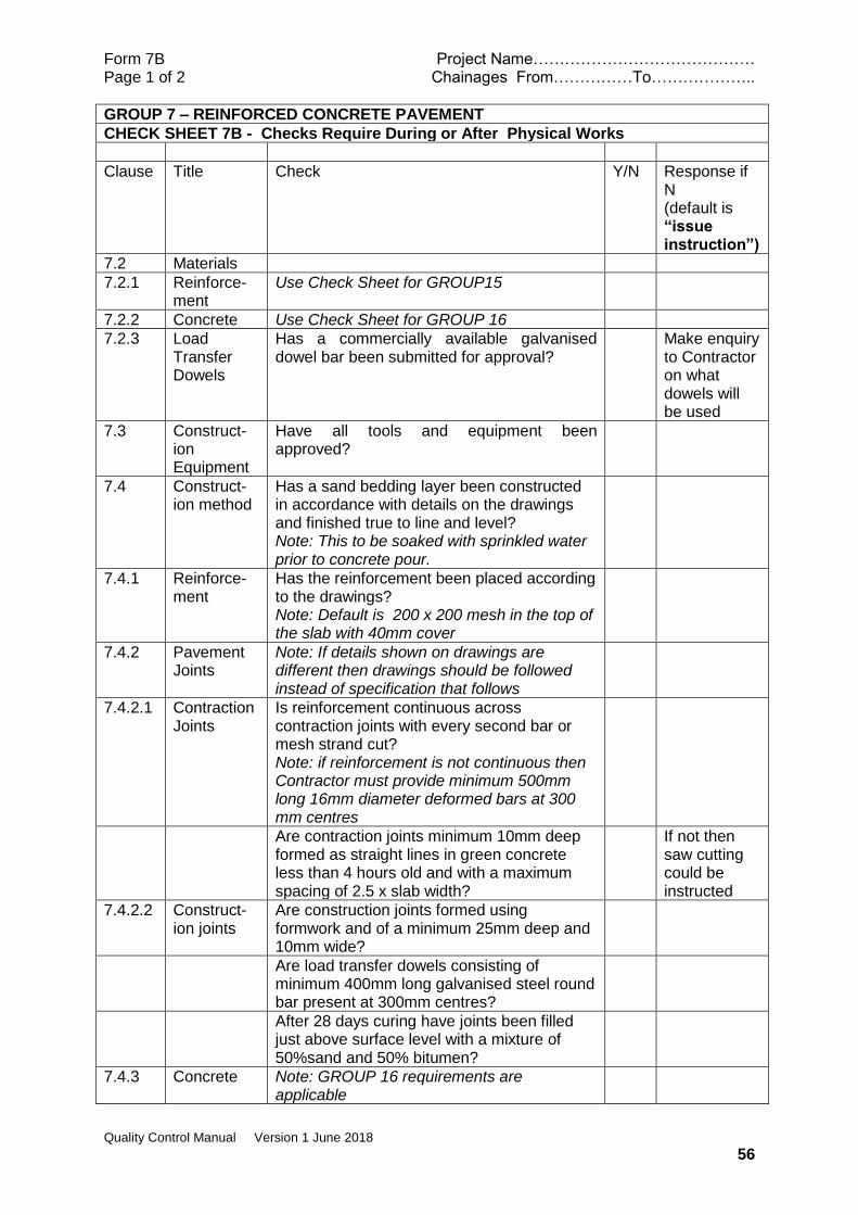
Form 7B Project Name…………………………………… Page 1 of 2 Chainages From……………To………………..
Quality Control Manual Version 1 June 2018
56
GROUP 7 – REINFORCED CONCRETE PAVEMENT
CHECK SHEET 7B - Checks Require During or After Physical Works
Clause Title Check Y/N Response if N (default is “issue instruction”)
7.2 Materials
7.2.1 Reinforce-ment
Use Check Sheet for GROUP15
7.2.2 Concrete Use Check Sheet for GROUP 16
7.2.3 Load Transfer Dowels
Has a commercially available galvanised dowel bar been submitted for approval?
Make enquiry to Contractor on what dowels will be used
7.3 Construct-ion Equipment
Have all tools and equipment been approved?
7.4 Construct-ion method
Has a sand bedding layer been constructed in accordance with details on the drawings and finished true to line and level? Note: This to be soaked with sprinkled water prior to concrete pour.
7.4.1 Reinforce-ment
Has the reinforcement been placed according to the drawings? Note: Default is 200 x 200 mesh in the top of the slab with 40mm cover
7.4.2 Pavement Joints
Note: If details shown on drawings are different then drawings should be followed instead of specification that follows
7.4.2.1 Contraction Joints
Is reinforcement continuous across contraction joints with every second bar or mesh strand cut? Note: if reinforcement is not continuous then Contractor must provide minimum 500mm long 16mm diameter deformed bars at 300 mm centres
Are contraction joints minimum 10mm deep formed as straight lines in green concrete less than 4 hours old and with a maximum spacing of 2.5 x slab width?
If not then saw cutting could be instructed
7.4.2.2 Construct-ion joints
Are construction joints formed using formwork and of a minimum 25mm deep and 10mm wide?
Are load transfer dowels consisting of minimum 400mm long galvanised steel round bar present at 300mm centres?
After 28 days curing have joints been filled just above surface level with a mixture of 50%sand and 50% bitumen?
7.4.3 Concrete Note: GROUP 16 requirements are applicable
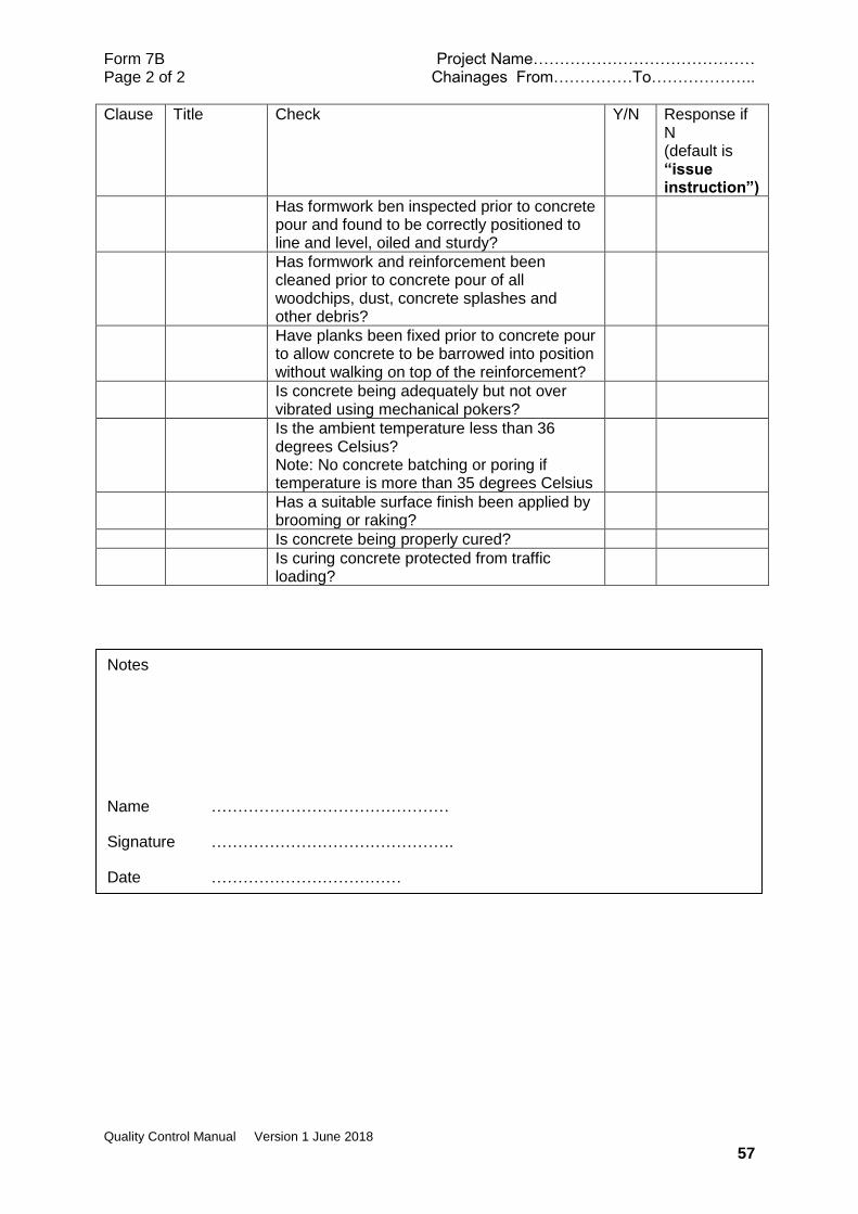
Form 7B Project Name…………………………………… Page 2 of 2 Chainages From……………To………………..
Quality Control Manual Version 1 June 2018
57
Clause Title Check Y/N Response if N (default is “issue instruction”)
Has formwork ben inspected prior to concrete pour and found to be correctly positioned to line and level, oiled and sturdy?
Has formwork and reinforcement been cleaned prior to concrete pour of all woodchips, dust, concrete splashes and other debris?
Have planks been fixed prior to concrete pour to allow concrete to be barrowed into position without walking on top of the reinforcement?
Is concrete being adequately but not over vibrated using mechanical pokers?
Is the ambient temperature less than 36 degrees Celsius? Note: No concrete batching or poring if temperature is more than 35 degrees Celsius
Has a suitable surface finish been applied by brooming or raking?
Is concrete being properly cured?
Is curing concrete protected from traffic loading?
Notes
Name ………………………………………
Signature ……………………………………….
Date ………………………………

Form 7C Project Name…………………………………… Page 1 of 1 Chainages From……………To………………..
Quality Control Manual Version 1 June 2018
58
GROUP 7 – REINFORCED CONCRETE PAVEMENT
CHECK SHEET 7C – Laboratory or Field Tests Required
clause Title Check Y/N Response
7.2 Materials GROUP 16 to apply
7.5 Laboratory and Site Testing
Slump test for every batch or as directed Test AS 1012.3.1
Notes
Name ………………………………………
Signature ……………………………………….
Date ………………………………

Form 7D Project Name…………………………………… Page 1 of 1 Chainages From……………To………………..
Quality Control Manual Version 1 June 2018
59
GROUP 7 – REINFORCED CONCRETE PAVEMENT
CHECK SHEET 7D – Measurement Records
Clause Title Check Unit Y/N
7.6 Measurement and Payment
All in rate m2
Dowels are not specifically mentioned but if not in the Bill of Quantities as a separate item they must be assumed to be included in the m2 rate. If they are a separate item then an agreed record (no of each type) will be useful
Notes
Name ………………………………………
Signature ……………………………………….
Date ………………………………
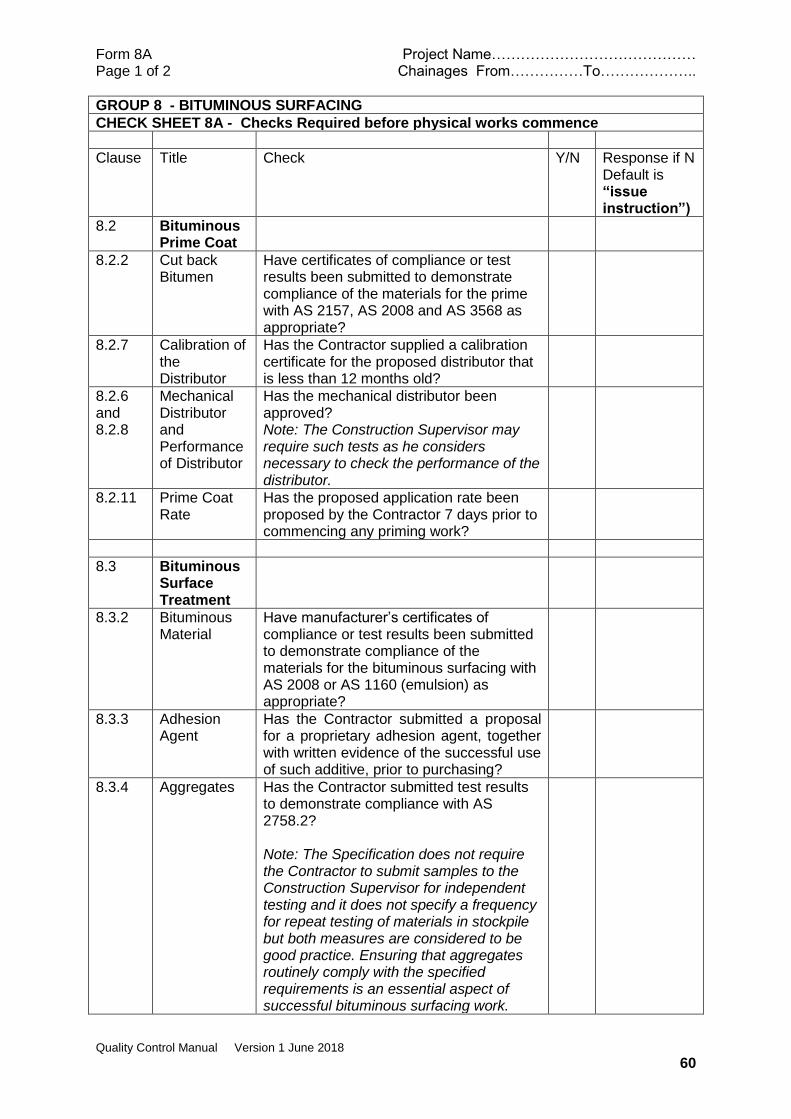
Form 8A Project Name…………………………………… Page 1 of 2 Chainages From……………To………………..
Quality Control Manual Version 1 June 2018
60
GROUP 8 - BITUMINOUS SURFACING
CHECK SHEET 8A - Checks Required before physical works commence
Clause Title Check Y/N Response if N Default is “issue instruction”)
8.2 Bituminous Prime Coat
8.2.2 Cut back Bitumen
Have certificates of compliance or test results been submitted to demonstrate compliance of the materials for the prime with AS 2157, AS 2008 and AS 3568 as appropriate?
8.2.7 Calibration of the Distributor
Has the Contractor supplied a calibration certificate for the proposed distributor that is less than 12 months old?
8.2.6 and 8.2.8
Mechanical Distributor and Performance of Distributor
Has the mechanical distributor been approved? Note: The Construction Supervisor may require such tests as he considers necessary to check the performance of the distributor.
8.2.11 Prime Coat Rate
Has the proposed application rate been proposed by the Contractor 7 days prior to commencing any priming work?
8.3 Bituminous Surface Treatment
8.3.2 Bituminous Material
Have manufacturer’s certificates of compliance or test results been submitted to demonstrate compliance of the materials for the bituminous surfacing with AS 2008 or AS 1160 (emulsion) as appropriate?
8.3.3 Adhesion Agent
Has the Contractor submitted a proposal for a proprietary adhesion agent, together with written evidence of the successful use of such additive, prior to purchasing?
8.3.4 Aggregates Has the Contractor submitted test results to demonstrate compliance with AS 2758.2? Note: The Specification does not require the Contractor to submit samples to the Construction Supervisor for independent testing and it does not specify a frequency for repeat testing of materials in stockpile but both measures are considered to be good practice. Ensuring that aggregates routinely comply with the specified requirements is an essential aspect of successful bituminous surfacing work.

Form 8A Project Name…………………………………… Page 1 of 2 Chainages From……………To………………..
Quality Control Manual Version 1 June 2018
61
Clause Title Check Y/N Response if N Default is “issue instruction”)
8.3.8 Plant and Equipment
Has the Contractor submitted details of the proposed equipment which demonstrates that it meets the requirements of this sub-clause of the Specification? Note: Although not specified it is common practice to require 2 rollers to mitigate the risk of a mechanical breakdown
8.3.10 Application Rate
Has the Contractor submitted for approval the details of the proposed application rate of bituminous binder material and cover aggregate at least seven (7) days prior to any sealing works commencing? Note: The application rate of bituminous binder material and cover aggregate shall be determined by the Contractor using the Update of the Austroads Sprayed Seal Design Method (AP-T68-06) and Update of Double / Double Design for Austroads Sprayed Seal Method (AP-T236-13) and Towards Incorporating Heavy Vehicles into the Austroads Sprayed Seal Design Method (AP-T260-14). The Contractor shall provide full design calculations including details of any assumptions
Notes
Name ………………………………………
Signature ……………………………………….
Date ………………………………
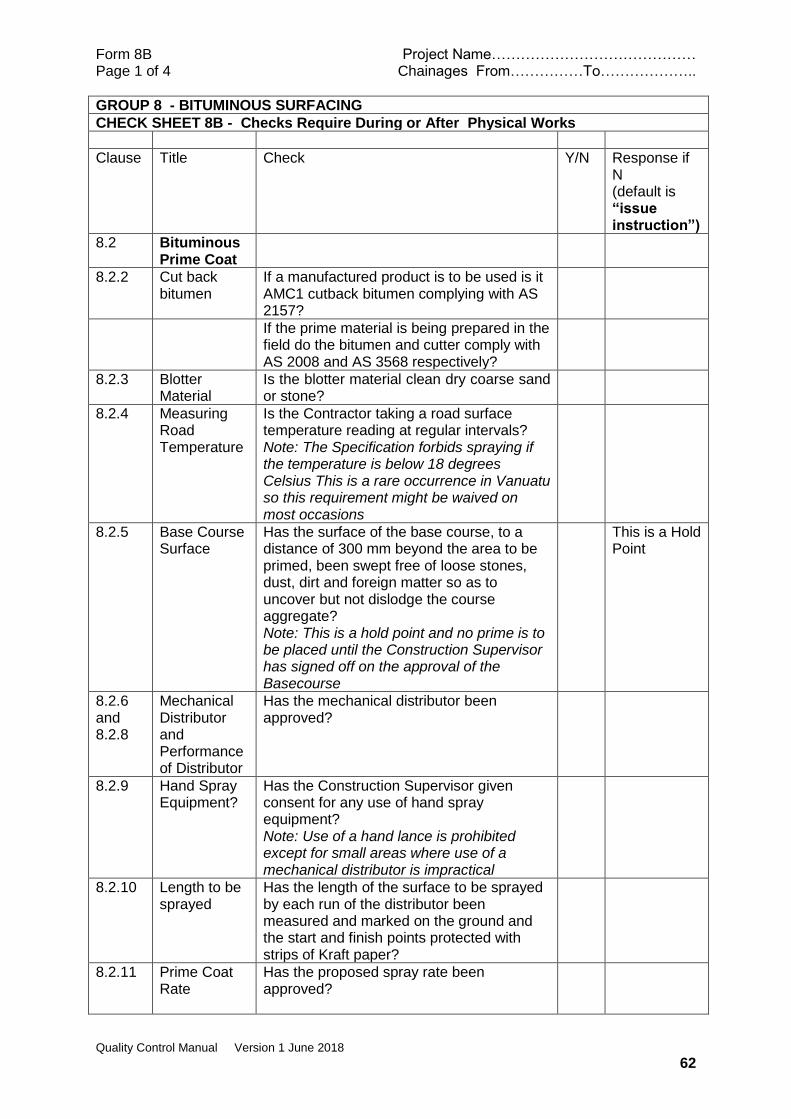
Form 8B Project Name…………………………………… Page 1 of 4 Chainages From……………To………………..
Quality Control Manual Version 1 June 2018
62
GROUP 8 - BITUMINOUS SURFACING
CHECK SHEET 8B - Checks Require During or After Physical Works
Clause Title Check Y/N Response if N (default is “issue instruction”)
8.2 Bituminous Prime Coat
8.2.2 Cut back bitumen
If a manufactured product is to be used is it AMC1 cutback bitumen complying with AS 2157?
If the prime material is being prepared in the field do the bitumen and cutter comply with AS 2008 and AS 3568 respectively?
8.2.3 Blotter Material
Is the blotter material clean dry coarse sand or stone?
8.2.4 Measuring Road Temperature
Is the Contractor taking a road surface temperature reading at regular intervals? Note: The Specification forbids spraying if the temperature is below 18 degrees Celsius This is a rare occurrence in Vanuatu so this requirement might be waived on most occasions
8.2.5 Base Course Surface
Has the surface of the base course, to a distance of 300 mm beyond the area to be primed, been swept free of loose stones, dust, dirt and foreign matter so as to uncover but not dislodge the course aggregate? Note: This is a hold point and no prime is to be placed until the Construction Supervisor has signed off on the approval of the Basecourse
This is a Hold Point
8.2.6 and 8.2.8
Mechanical Distributor and Performance of Distributor
Has the mechanical distributor been approved?
8.2.9 Hand Spray Equipment?
Has the Construction Supervisor given consent for any use of hand spray equipment? Note: Use of a hand lance is prohibited except for small areas where use of a mechanical distributor is impractical
8.2.10 Length to be sprayed
Has the length of the surface to be sprayed by each run of the distributor been measured and marked on the ground and the start and finish points protected with strips of Kraft paper?
8.2.11 Prime Coat Rate
Has the proposed spray rate been approved?
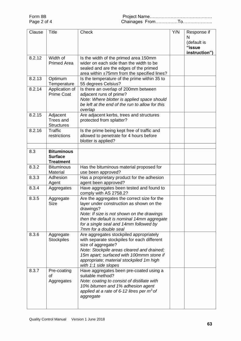
Form 8B Project Name…………………………………… Page 2 of 4 Chainages From……………To………………..
Quality Control Manual Version 1 June 2018
63
Clause Title Check Y/N Response if N (default is “issue instruction”)
8.2.12 Width of Primed Area
Is the width of the primed area 150mm wider on each side than the width to be sealed and are the edges of the primed area within ±75mm from the specified lines?
8.2.13 Optimum Temperature
Is the temperature of the prime within 35 to 55 degrees Celsius?
8.2.14 Application of Prime Coat
Is there an overlap of 200mm between adjacent runs of prime? Note: Where blotter is applied space should be left at the end of the run to allow for this overlap
8.2.15 Adjacent Trees and Structures
Are adjacent kerbs, trees and structures protected from splatter?
8.2.16 Traffic restrictions
Is the prime being kept free of traffic and allowed to penetrate for 4 hours before blotter is applied?
8.3 Bituminous Surface Treatment
8.3.2 Bituminous Material
Has the bituminous material proposed for use been approved?
8.3.3 Adhesion Agent
Has a proprietary product for the adhesion agent been approved?
8.3.4 Aggregates Have aggregates been tested and found to comply with AS 2758.2?
8.3.5 Aggregate Size
Are the aggregates the correct size for the layer under construction as shown on the drawings? Note: If size is not shown on the drawings then the default is nominal 14mm aggregate for a single seal and 14mm followed by 7mm for a double seal
8.3.6 Aggregate Stockpiles
Are aggregates stockpiled appropriately with separate stockpiles for each different size of aggregate? Note: Stockpile areas cleared and drained; 15m apart; surfaced with 100mmm stone if appropriate; material stockpiled 1m high with 1:1 side slopes
8.3.7 Pre-coating of Aggregates
Have aggregates been pre-coated using a suitable method? Note: coating to consist of distillate with 10% bitumen and 1% adhesion agent applied at a rate of 6-12 litres per m3.of aggregate
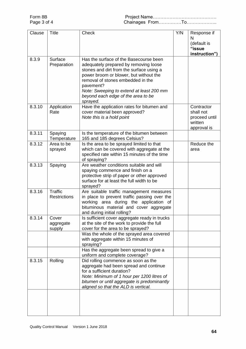
Form 8B Project Name…………………………………… Page 3 of 4 Chainages From……………To………………..
Quality Control Manual Version 1 June 2018
64
Clause Title Check Y/N Response if N (default is “issue instruction”)
8.3.9 Surface Preparation
Has the surface of the Basecourse been adequately prepared by removing loose stones and dirt from the surface using a power broom or blower, but without the removal of stones embedded in the pavement? Note: Sweeping to extend at least 200 mm beyond each edge of the area to be sprayed.
8.3.10 Application Rate
Have the application rates for bitumen and cover material been approved? Note this is a hold point
Contractor shall not proceed until written approval is
8.3.11 Spaying Temperature
Is the temperature of the bitumen between 165 and 185 degrees Celsius?
8.3.12 Area to be sprayed
Is the area to be sprayed limited to that which can be covered with aggregate at the specified rate within 15 minutes of the time of spraying?
Reduce the area
8.3.13 Spaying Are weather conditions suitable and will spaying commence and finish on a protective strip of paper or other approved surface for at least the full width to be sprayed?
8.3.16 Traffic Restrictions
Are suitable traffic management measures in place to prevent traffic passing over the working area during the application of bituminous material and cover aggregate and during initial rolling?
8.3.14 Cover aggregate supply
Is sufficient cover aggregate ready in trucks at the site of the work to provide the full cover for the area to be sprayed?
Was the whole of the sprayed area covered with aggregate within 15 minutes of spraying?
Has the aggregate been spread to give a uniform and complete coverage?
8.3.15 Rolling Did rolling commence as soon as the aggregate had been spread and continue for a sufficient duration? Note: Minimum of 1 hour per 1200 litres of bitumen or until aggregate is predominantly aligned so that the ALD is vertical.
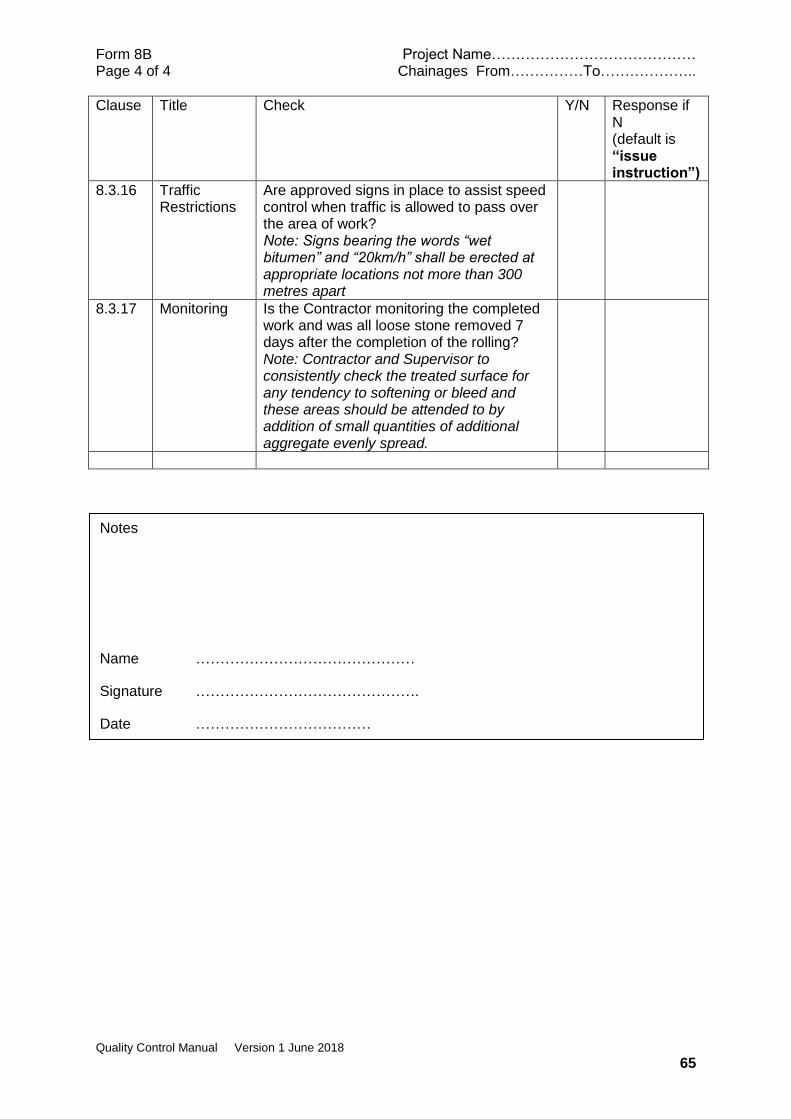
Form 8B Project Name…………………………………… Page 4 of 4 Chainages From……………To………………..
Quality Control Manual Version 1 June 2018
65
Clause Title Check Y/N Response if N (default is “issue instruction”)
8.3.16 Traffic Restrictions
Are approved signs in place to assist speed control when traffic is allowed to pass over the area of work? Note: Signs bearing the words “wet bitumen” and “20km/h” shall be erected at appropriate locations not more than 300 metres apart
8.3.17 Monitoring Is the Contractor monitoring the completed work and was all loose stone removed 7 days after the completion of the rolling? Note: Contractor and Supervisor to consistently check the treated surface for any tendency to softening or bleed and these areas should be attended to by addition of small quantities of additional aggregate evenly spread.
Notes
Name ………………………………………
Signature ……………………………………….
Date ………………………………
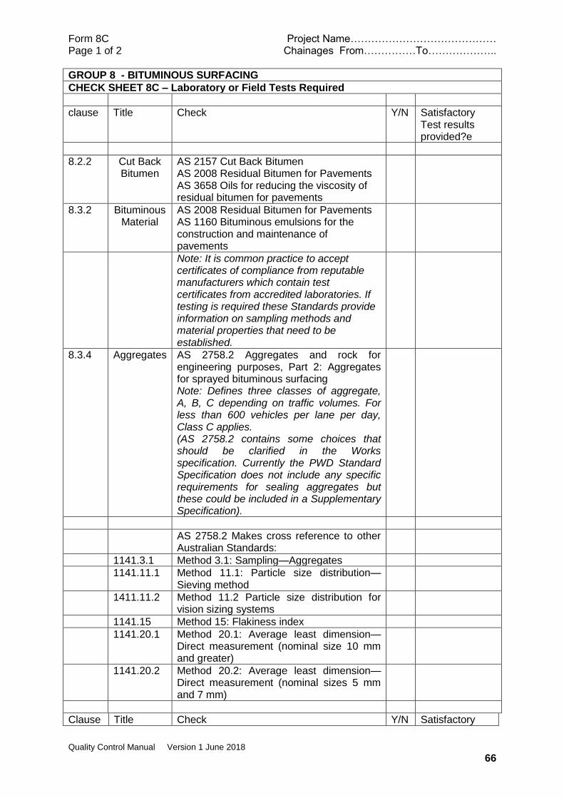
Form 8C Project Name…………………………………… Page 1 of 2 Chainages From……………To………………..
Quality Control Manual Version 1 June 2018
66
GROUP 8 - BITUMINOUS SURFACING
CHECK SHEET 8C – Laboratory or Field Tests Required
clause Title Check Y/N Satisfactory Test results provided?e
8.2.2 Cut Back Bitumen
AS 2157 Cut Back Bitumen AS 2008 Residual Bitumen for Pavements AS 3658 Oils for reducing the viscosity of residual bitumen for pavements
8.3.2 Bituminous Material
AS 2008 Residual Bitumen for Pavements AS 1160 Bituminous emulsions for the construction and maintenance of pavements
Note: It is common practice to accept certificates of compliance from reputable manufacturers which contain test certificates from accredited laboratories. If testing is required these Standards provide information on sampling methods and material properties that need to be established.
8.3.4 Aggregates AS 2758.2 Aggregates and rock for engineering purposes, Part 2: Aggregates for sprayed bituminous surfacing Note: Defines three classes of aggregate, A, B, C depending on traffic volumes. For less than 600 vehicles per lane per day, Class C applies. (AS 2758.2 contains some choices that should be clarified in the Works specification. Currently the PWD Standard Specification does not include any specific requirements for sealing aggregates but these could be included in a Supplementary Specification).
AS 2758.2 Makes cross reference to other Australian Standards:
1141.3.1 Method 3.1: Sampling—Aggregates
1141.11.1 Method 11.1: Particle size distribution—Sieving method
1411.11.2 Method 11.2 Particle size distribution for vision sizing systems
1141.15 Method 15: Flakiness index
1141.20.1 Method 20.1: Average least dimension—Direct measurement (nominal size 10 mm and greater)
1141.20.2 Method 20.2: Average least dimension—Direct measurement (nominal sizes 5 mm and 7 mm)
Clause Title Check Y/N Satisfactory
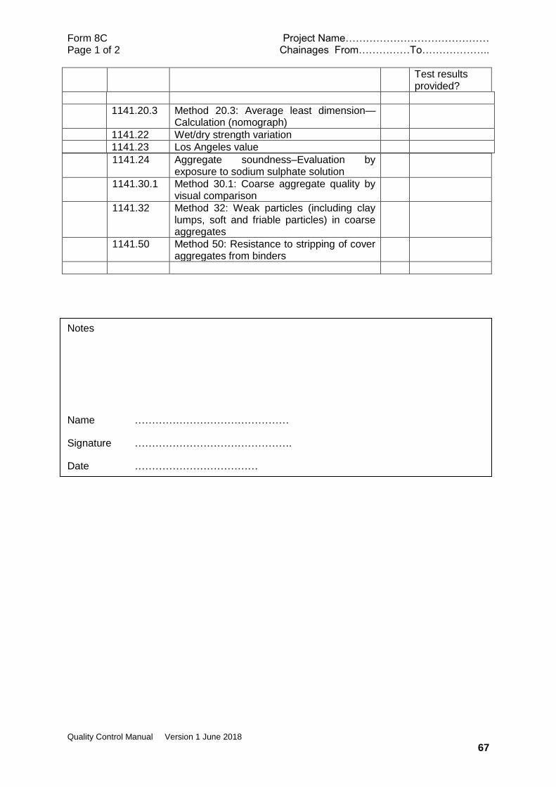
Form 8C Project Name…………………………………… Page 1 of 2 Chainages From……………To………………..
Quality Control Manual Version 1 June 2018
67
Test results provided?
1141.20.3 Method 20.3: Average least dimension—Calculation (nomograph)
1141.22 Wet/dry strength variation
1141.23 Los Angeles value
1141.24 Aggregate soundness–Evaluation by exposure to sodium sulphate solution
1141.30.1 Method 30.1: Coarse aggregate quality by visual comparison
1141.32 Method 32: Weak particles (including clay lumps, soft and friable particles) in coarse aggregates
1141.50 Method 50: Resistance to stripping of cover aggregates from binders
Notes
Name ………………………………………
Signature ……………………………………….
Date ………………………………
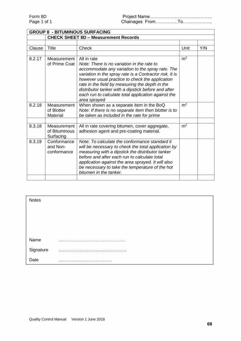
Form 8D Project Name…………………………………… Page 1 of 1 Chainages From……………To………………..
Quality Control Manual Version 1 June 2018
68
GROUP 8 - BITUMINOUS SURFACING
CHECK SHEET 8D – Measurement Records
Clause Title Check Unit Y/N
8.2.17 Measurement of Prime Coat
All in rate Note: There is no variation in the rate to accommodate any variation to the spray rate. The variation in the spray rate is a Contractor risk. It is however usual practice to check the application rate in the field by measuring the depth in the distributor tanker with a dipstick before and after each run to calculate total application against the area sprayed
m2
8.2.18 Measurement of Blotter Material
When shown as a separate item in the BoQ Note: If there is no separate item then blotter is to be taken as included in the rate for prime
m2
8.3.18 Measurement of Bituminous Surfacing
All in rate covering bitumen, cover aggregate, adhesion agent and pre-coating material.
m2
8.3.19 Conformance and Non-conformance
Note: To calculate the conformance standard it will be necessary to check the total application by measuring with a dipstick the distributor tanker before and after each run to calculate total application against the area sprayed. It will also be necessary to take the temperature of the hot bitumen in the tanker.
Notes
Name ………………………………………
Signature ……………………………………….
Date ………………………………
Form 9A Project Name…………………………………… Page 1 of 3 Chainages From……………To………………..
Quality Control Manual Version 1 June 2018
69
GROUP 9 - DRAINAGE
CHECK SHEET 9A - Checks Required before physical works commence
Clause Title Check Y/N Response if N Default is “issue instruction”)
9.1 General Do the drawings show all initially planned drainage lines with sufficient details for construction i.e. alignment and levels, type and size?
9.2 Materials
9.2.1 Reinforced Concrete Pipes
Has the Contractor demonstrated satisfactorily that RC pipes that have or will be brought to the Site have been manufactured in conformance to AS 4058?
Do not accept until compliance has been demonstrated
Has testing in accordance with AS 4058 been carried out at the place of manufacture in the presence of the Construction Supervisor? Note: if precast pipes are being imported and the manufacturer has a QA system that is accredited to ISO 9004 standard or uses a third party certification scheme, then consideration might be given to relaxing this requirement. AS 4058 allows a third part product certification scheme
Are pipes delivered to Site the correct type and class? Note: Default is rubber ring spigot and socket joints and class 3
Are pipes delivered to Site free from defects and damage?
Reject or Instruct testing or other measures in regard to damaged or repaired pipes
9.2.3 Corrugated Steel
Has the Contractor satisfactorily demonstrated that corrugated steel pipes that have or will be brought to the Site have been manufactured in conformance to AS 2041?
Do not accept until compliance has been demonstrated
9.2.3.1 Nestable and Boltable
Have plates been shop rolled to increase the vertical dimension by 5%
Query this requirement
9.2.3.2 Helical lock seam
Has the Contractor satisfactorily demonstrated that helical lock seam pipes that have or will be brought to the Site have been manufactured in conformance to AS 1761?
Do not accept until compliance has been demonstrated
Are there any welded joints in the pipes?

Form 9A Project Name…………………………………… Page 2 of 3 Chainages From……………To………………..
Quality Control Manual Version 1 June 2018
70
Clause Title Check Y/N Response if N Default is “issue instruction”)
9.2.4 Precast Concrete Box Culverts
Has the Contractor satisfactorily demonstrated that precast concrete box culverts that have or will be brought to the Site have been manufactured in conformance to AS 1597?
Do not accept until compliance has been demonstrated
Has testing in accordance with AS 1597 been carried out at the place of manufacture in the presence of the Construction Supervisor? Note: if precast concrete culverts are being imported and the manufacturer has a QA system that is accredited to ISO 9004 standard or uses a third party certification scheme, then consideration might be given to relaxing this requirement. AS 527 allows these methods of product compliance
Are the date of manufacture and the name of trademark of the manufacturer marked on each culvert section?
Are box culverts delivered to Site the correct class?
Are pipes delivered to Site free from defects and damage?
Reject or Instruct testing or other measures in regard to damaged or repaired pipes
If a Contractor’s design is required for an insitu base slab, has this been provided and approved?
Are the proposed lifting arrangements considered to be satisfactory?
If the whole of the box culvert is to be manufactured on the Site, have the required design details and method statement been provided (at least two weeks prior to proposed start of manufacture)
9.4.5 Placing Precast Concrete Box Culvert
Have installation instructions been provided by the manufacturer or shown on drawings?
9.3 Excavation and Bedding
Has the method for disposal of surplus excavated material been approved?
Is trench construction method required?

Form 9A Project Name…………………………………… Page 3 of 3 Chainages From……………To………………..
Quality Control Manual Version 1 June 2018
71
Clause Title Check Y/N Response if N Default is “issue instruction”)
9.4 Placing Have all fasteners for bolted corrugated metal structures been shown to comply with AS 1112?
9.4.3.1 Corrugated Steel Pipe - Helical Lock Seal
Have pipes and coupling bands been given hot dipped bitumen coating as part of the manufacturing process?
Have the ends of helical lock seal pipes been re-rolled with 4 annular corrugations of 68mm where joints will be made on site?
9.7 Taking Up and Stacking
Are any instructions required for taking up existing culverts?
9.10 Subsoil Drainage
Has the Contractor satisfactorily demonstrated that sub-soil drains that have or will be brought to the Site have been manufactured in conformance to AS 2439.1?
Do not accept until compliance has been demonstrated
Are construction details and locations shown on drawings? Type A construction is the default if details not shown on drawings.
Instruct locations if necessary.
9.11 Lined Drains
9.11.2 Stone pitched Lined Drains
Is rock proposed for the work suitable? Note: Sound, durable stones with size not less than .001 m3 with least dimension of 75mm
9.11.4 Precast Concrete Lined drains
Has the Contractor submitted details of formwork and casting procedures for precast concrete units for prior approval? Note: Manufacture should not commence until procedures have been approved
9.13 Kerbs, Channels and Edge Strips
9.13.3 Cast Insitu by extrusion Machine
Has the Contractor provided a satisfactory test section?
Notes
Name ………………………………………
Signature ……………………………………….
Date ………………………………
Form 9B Project Name…………………………………… Page 1 of 6 Chainages From……………To………………..
Quality Control Manual Version 1 June 2018
72
GROUP 9 - DRAINAGE
CHECK SHEET 9B - Checks Require During or After Physical Works
Clause Title Check Y/N Response if N (default is “issue instruction”)
9.2.2 Mortar for Joints
Are the constituents and moisture content of mortar for jointing satisfactory?
9.2.3.2 Helical lock seam
Have any/all field cut ends been treated as specified?
9.3 Excavation and Bedding
Has excavation been carried out to the correct line and levels?
Is width of trench acceptable? Note :(Minimum of culvert width plus 600mm and not excessively wider).
Has the foundation material in trench bottom been inspected prior to placing of bedding material and pipes? Note: It would be useful if this was a Hold Point
If foundation material is suitable, has it been compacted satisfactorily?
If foundation is rock has additional 150mm been excavated?
Has this additional rock excavation been backfilled with compacted selected material?
If foundation material (other than rock) is unacceptable has the depth (and width) of additional excavation been instructed? Note: width to be 1.5 x culvert diameter or span
Is bedding material acceptable and has it been adequately shaped? Note: Minimum depth 75mm plus one tenth of the culvert diameter for shaping
9.4 Placing
9.4.1 Reinforced Concrete Pipe
Is installation progressing from the outlet end towards the inlet end and are socket ends facing in the upstream direction?
If there is a ‘top side has this been placed correctly?
Are conditions suitable for mortar jointing to commence?
If the culvert has more than one barrel are they spaced in accordance with the drawing?
Have pipes been placed without undue settlement and damage?
9.4.2 Corrugated Steel Pipe - Nestable
Is installation progressing from the inlet end towards the outlet end with bottom sheets one sheet ahead of full circle construction?
Form 9B Project Name…………………………………… Page 2 of 6 Chainages From……………To………………..
Quality Control Manual Version 1 June 2018
73
Clause Title Check Y/N Response if N Default is “issue instruction”)
When sections are added are they outside the one already placed?
Are longitudinal joints in the same horizontal plane and circumferential joints staggered?
Have joints been covered with a suitable geotextile cloth prior to commencing backfilling?
If the culvert has more than one barrel are they spaced in accordance with the drawing?
Have pipes been placed without undue settlement and damage?
9.4.3 Corrugated Steel Pipe Bolted
Is work progressing from the outlet end with all bottom plates being placed first?
9.4.3.2 Corrosion Protection
Have bottom plates been painted on the outside before placing?
9.4.3 Corrugated Steel Pipe Bolted
Is placing of side and top plates commencing from the inlet end and with side plate only sufficiently ahead of top plates to ensure stability?
Have bolts been left untightened until all plates ae assembled?
After all plates are assembled have all bolts been inserted and tightened then rechecked?
If the culvert has more than one barrel are they spaced in accordance with the drawing?
9.4.3.1 Corrugated Steel Pipe-Helical Lockseal
Is installation according to AS 1726? Note the following requirements which differ from other parts of the Standard Specification
(i) If foundation material is unsuitable trench width to be 2 x diameter
(ii) If rock foundation extra excavation is the lesser of diameter/4 or 250mm
(iii) loose (iv) granular material of 12 mm
maximum aggregate size shall cover the shaped bedding of a firm foundation to a depth sufficient to allow the corrugations to become filled with the material.
Form 9B Project Name…………………………………… Page 3 of 6 Chainages From……………To………………..
Quality Control Manual Version 1 June 2018
74
Clause Title Check Y/N Response if N Default is “issue instruction”)
Have all field cut ends been prepared and painted as specified?
Have joints been covered with a suitable geotextile prior to backfilling?
If the culvert has more than one barrel are they spaced in accordance with the drawing?
Have pipes been placed without undue settlement and damage?
9.4.3.2 Corrosion Protection of Corrugated Steel Pipes
Has a suitable protective coating been applied?
9.4.5 Precast Concrete Box Culverts
Are the manufacturer’s instructions or other approved installation method been followed?
Has a gap of 15mm been maintained between adjacent cells?
Has the gap been filled with approved filler?
Are mortared joints protected from the sun for 48 hours?
9.5 Backfilling Has approval been given for backfilling to commence? Note: It is a hold point for inspection and approval to be given before backfill commences
Is the backfill material suitable? Note: Granular material; Maximum size 75mm; at least 50% <2.36 mm; no boulders or organic material; maximum PI of 12.
Is the backfill being placed in layers not exceeding 150mm?
Is the backfill being placed on both sides of the culvert at the same time with a maximum difference in level of 150mm?
Is material under the haunches and near the sides being compacted with hand held equipment?
Is compaction being tested and meeting the required standard?
Has adequate cover material been placed above the top of the culvert? Note 300mm above top and one diameter either side or half the wall height for embankment condition and full depth of trench for trench condition.
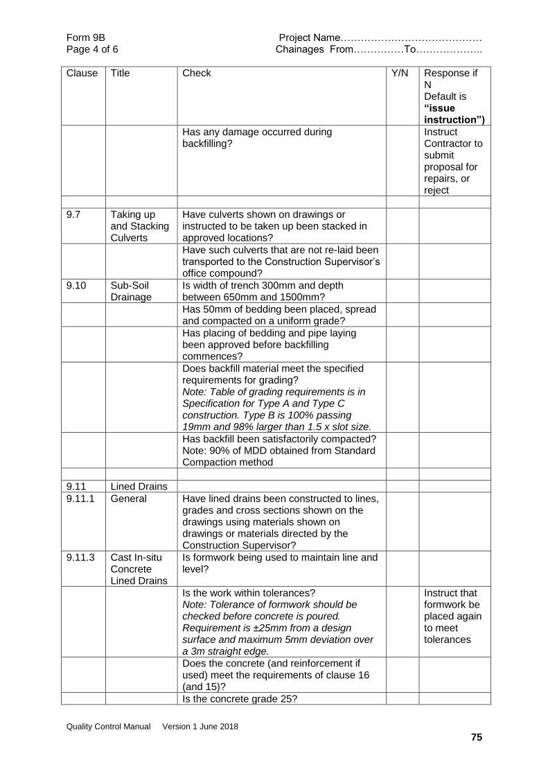
Form 9B Project Name…………………………………… Page 4 of 6 Chainages From……………To………………..
Quality Control Manual Version 1 June 2018
75
Clause Title Check Y/N Response if N Default is “issue instruction”)
Has any damage occurred during backfilling?
Instruct Contractor to submit proposal for repairs, or reject
9.7 Taking up and Stacking Culverts
Have culverts shown on drawings or instructed to be taken up been stacked in approved locations?
Have such culverts that are not re-laid been transported to the Construction Supervisor’s office compound?
9.10 Sub-Soil Drainage
Is width of trench 300mm and depth between 650mm and 1500mm?
Has 50mm of bedding been placed, spread and compacted on a uniform grade?
Has placing of bedding and pipe laying been approved before backfilling commences?
Does backfill material meet the specified requirements for grading? Note: Table of grading requirements is in Specification for Type A and Type C construction. Type B is 100% passing 19mm and 98% larger than 1.5 x slot size.
Has backfill been satisfactorily compacted? Note: 90% of MDD obtained from Standard Compaction method
9.11 Lined Drains
9.11.1 General Have lined drains been constructed to lines, grades and cross sections shown on the drawings using materials shown on drawings or materials directed by the Construction Supervisor?
9.11.3 Cast In-situ Concrete Lined Drains
Is formwork being used to maintain line and level?
Is the work within tolerances? Note: Tolerance of formwork should be checked before concrete is poured. Requirement is ±25mm from a design surface and maximum 5mm deviation over a 3m straight edge.
Instruct that formwork be placed again to meet tolerances
Does the concrete (and reinforcement if used) meet the requirements of clause 16 (and 15)?
Is the concrete grade 25?
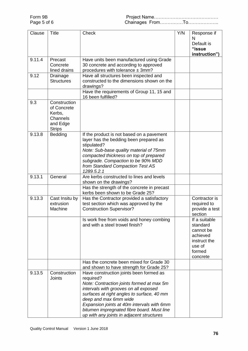
Form 9B Project Name…………………………………… Page 5 of 6 Chainages From……………To………………..
Quality Control Manual Version 1 June 2018
76
Clause Title Check Y/N Response if N Default is “issue instruction”)
9.11.4 Precast Concrete lined drains
Have units been manufactured using Grade 30 concrete and according to approved procedures with tolerance ± 3mm?
9.12 Drainage Structures
Have all structures been inspected and constructed to the dimensions shown on the drawings?
Have the requirements of Group 11, 15 and 16 been fulfilled?
9.3 Construction of Concrete Kerbs, Channels and Edge Strips
9.13.8 Bedding If the product is not based on a pavement layer has the bedding been prepared as stipulated? Note: Sub-base quality material of 75mm compacted thickness on top of prepared subgrade. Compaction to be 90% MDD from Standard Compaction Test AS 1289.5.2.1
9.13.1 General Are kerbs constructed to lines and levels shown on the drawings?
Has the strength of the concrete in precast kerbs been shown to be Grade 25?
9.13.3 Cast Insitu by extrusion Machine
Has the Contractor provided a satisfactory test section which was approved by the Construction Supervisor?
Contractor is required to provide a test section
Is work free from voids and honey combing and with a steel trowel finish?
If a suitable standard cannot be achieved instruct the use of formed concrete
Has the concrete been mixed for Grade 30 and shown to have strength for Grade 25?
9.13.5 Construction Joints
Have construction joints been formed as required? Note: Contraction joints formed at max 5m intervals with grooves on all exposed surfaces at right angles to surface, 40 mm deep and max 6mm wide Expansion joints at 40m intervals with 6mm bitumen impregnated fibre board. Must line up with any joints in adjacent structures

Form 9B Project Name…………………………………… Page 6 of 6 Chainages From……………To………………..
Quality Control Manual Version 1 June 2018
77
Clause Title Check Y/N Response if N Default is “issue instruction”)
9.13.6 Curing Is all insitu concrete being cured in a satisfactory manner?
9.13.7 Tolerances Are alignments of kerbs and channels smooth with tolerance of ±10mm?
Notes
Name ………………………………………
Signature ……………………………………….
Date ………………………………
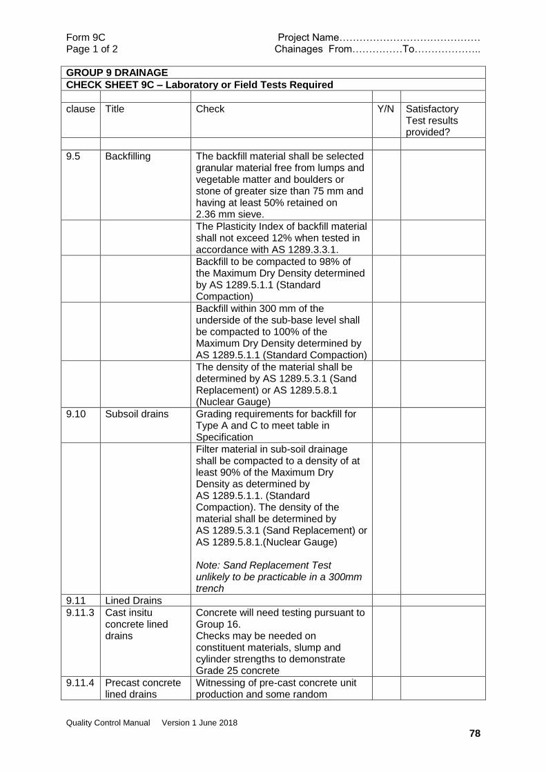
Form 9C Project Name…………………………………… Page 1 of 2 Chainages From……………To………………..
Quality Control Manual Version 1 June 2018
78
GROUP 9 DRAINAGE
CHECK SHEET 9C – Laboratory or Field Tests Required
clause Title Check Y/N Satisfactory Test results provided?
9.5 Backfilling The backfill material shall be selected granular material free from lumps and vegetable matter and boulders or stone of greater size than 75 mm and having at least 50% retained on 2.36 mm sieve.
The Plasticity Index of backfill material shall not exceed 12% when tested in accordance with AS 1289.3.3.1.
Backfill to be compacted to 98% of the Maximum Dry Density determined by AS 1289.5.1.1 (Standard Compaction)
Backfill within 300 mm of the underside of the sub-base level shall be compacted to 100% of the Maximum Dry Density determined by AS 1289.5.1.1 (Standard Compaction)
The density of the material shall be determined by AS 1289.5.3.1 (Sand Replacement) or AS 1289.5.8.1 (Nuclear Gauge)
9.10 Subsoil drains Grading requirements for backfill for Type A and C to meet table in Specification
Filter material in sub-soil drainage shall be compacted to a density of at least 90% of the Maximum Dry Density as determined by AS 1289.5.1.1. (Standard Compaction). The density of the material shall be determined by AS 1289.5.3.1 (Sand Replacement) or AS 1289.5.8.1.(Nuclear Gauge) Note: Sand Replacement Test unlikely to be practicable in a 300mm trench
9.11 Lined Drains
9.11.3 Cast insitu concrete lined drains
Concrete will need testing pursuant to Group 16. Checks may be needed on constituent materials, slump and cylinder strengths to demonstrate Grade 25 concrete
9.11.4 Precast concrete lined drains
Witnessing of pre-cast concrete unit production and some random

Form 9C Project Name…………………………………… Page 1 of 2 Chainages From……………To………………..
Quality Control Manual Version 1 June 2018
79
independent materials and concrete testing may be advisable
clause Title Check Y/N Response
9.13.3 Cast Insitu by extrusion Machine
Concrete strength of 25MPa required. Random verification testing is recommended
9.13.8 Preparation and Bedding
Compaction testing of bedding to 90% MDD using AS 1289.5.2.1
Notes
Name ………………………………………
Signature ……………………………………….
Date ………………………………
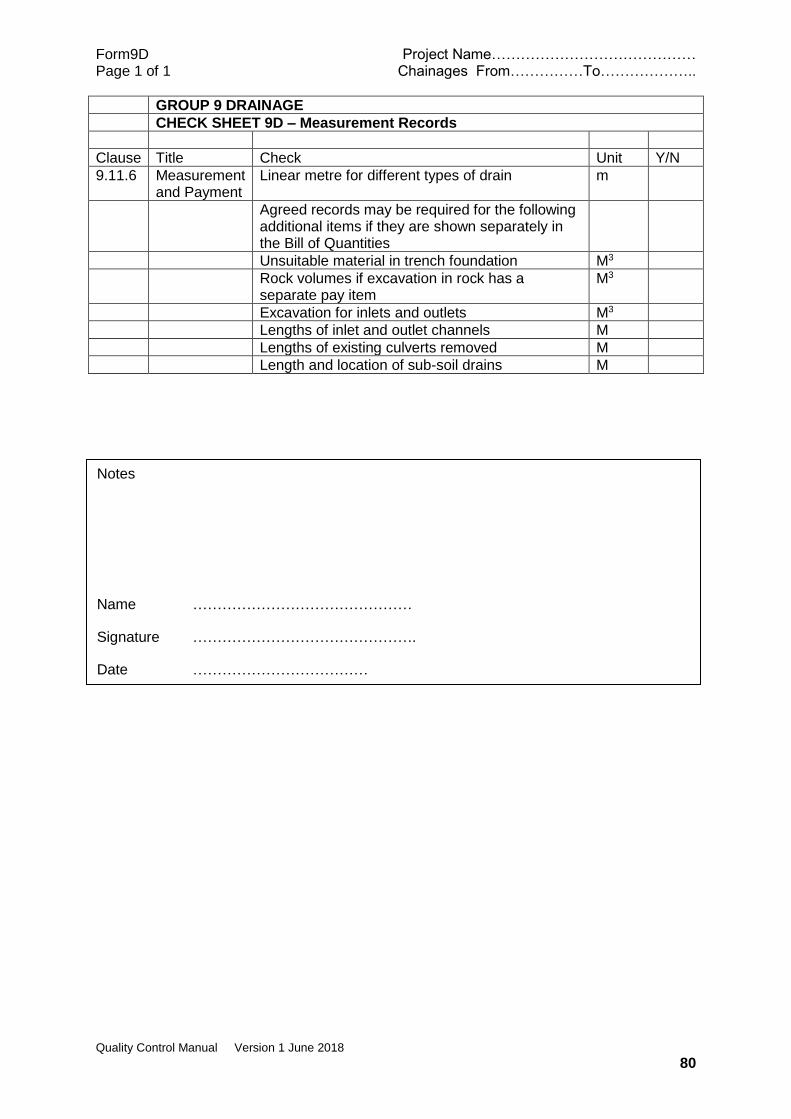
Form9D Project Name…………………………………… Page 1 of 1 Chainages From……………To………………..
Quality Control Manual Version 1 June 2018
80
GROUP 9 DRAINAGE
CHECK SHEET 9D – Measurement Records
Clause Title Check Unit Y/N
9.11.6 Measurement and Payment
Linear metre for different types of drain m
Agreed records may be required for the following additional items if they are shown separately in the Bill of Quantities
Unsuitable material in trench foundation M3
Rock volumes if excavation in rock has a separate pay item
M3
Excavation for inlets and outlets M3
Lengths of inlet and outlet channels M
Lengths of existing culverts removed M
Length and location of sub-soil drains M
Notes
Name ………………………………………
Signature ……………………………………….
Date ………………………………

Form 10A Project Name…………………………………… Page 1 of 2 Chainages From……………To………………..
Quality Control Manual Version 1 June 2018
81
GROUP 10 – ROAD FURNITURE AND MARKINGS
CHECK SHEET 10A - Checks Required before physical works commence
Clause Title Check Y/N Response if N Default is “issue instruction”)
10.1 Road Signs
General Do the drawings and/or Schedules show all the road signs that will be required and their locations? Note: AS 1742.2 contains information on the positioning of signs
Prepare and issue a schedule
10.1.2 Standard Has the Contractor shown satisfactory evidence that all signs that have or will be delivered to the Site are manufactured in accordance with AS 1743? Not: The Standard provides graphics, layout and size requirements together with an abridged materials and manufacturing specification
Do retroreflective materials conform in colour and Grade to AS 1743 Appendix C for Class 2 materials and with AS 1906.1? Note: There is no Appendix C or mention of Class 2 materials in AS 1743. This appears to be an error in the Specification
Are details of sign construction, including sign materials, stiffeners, posts, fasteners and foundations shown on drawings or in the Supplementary Specification?
Construction Supervisor may need to issue additional information
10.2 Guard Rails Are the locations and details of guard rails shown on the drawings and/or schedules?
Construction Supervisor may need to issue additional information
10.2.2 Timber posts for guardrail
If the Contractor intends to use timber posts, is the timber of an acceptable type and strength group and has it been pressure treated with preservative? Note: Strength group SD3 to AS 2878. Pressure treated with chrome arsenic solution with retention 0.032 gram per cubic centimetre
Approval needed prior to construction
10.2.3 Steel Beam Guard Rail
Has the Contractor demonstrated that guard rails that have or will be delivered to the site meet the specified requirements? Note: Guard Rails to be Armco Flexbeam or similar approved. Surface treatment to AS 1627.4 of 1627.5 then galvanising to AS 4680
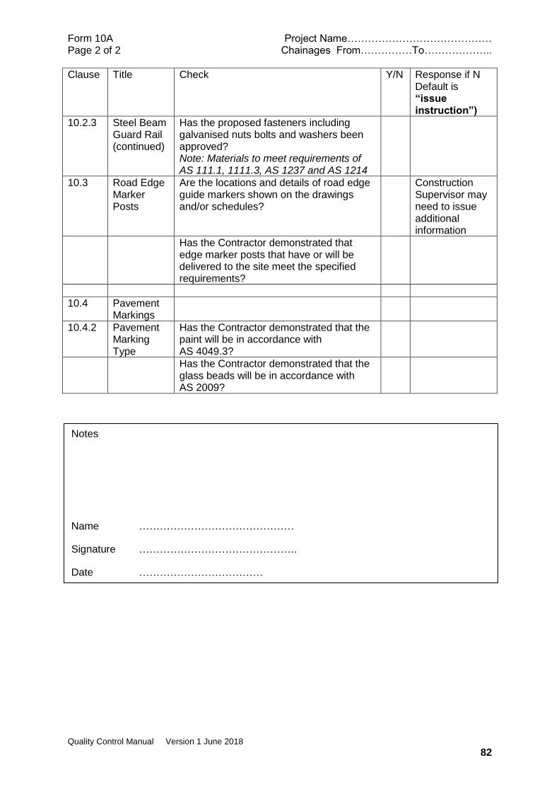
Form 10A Project Name…………………………………… Page 2 of 2 Chainages From……………To………………..
Quality Control Manual Version 1 June 2018
82
Clause Title Check Y/N Response if N Default is “issue instruction”)
10.2.3 Steel Beam Guard Rail (continued)
Has the proposed fasteners including galvanised nuts bolts and washers been approved? Note: Materials to meet requirements of AS 111.1, 1111.3, AS 1237 and AS 1214
10.3 Road Edge Marker Posts
Are the locations and details of road edge guide markers shown on the drawings and/or schedules?
Construction Supervisor may need to issue additional information
Has the Contractor demonstrated that edge marker posts that have or will be delivered to the site meet the specified requirements?
10.4 Pavement Markings
10.4.2 Pavement Marking Type
Has the Contractor demonstrated that the paint will be in accordance with AS 4049.3?
Has the Contractor demonstrated that the glass beads will be in accordance with AS 2009?
Notes
Name ………………………………………
Signature ……………………………………….
Date ………………………………
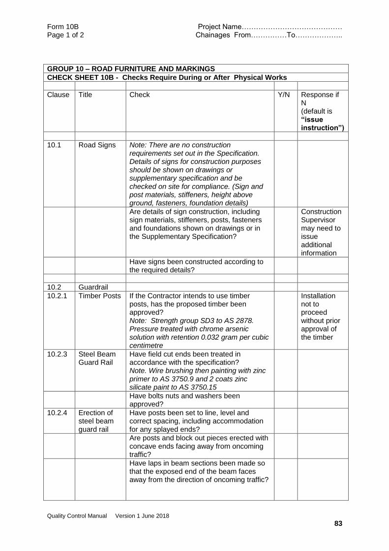
Form 10B Project Name…………………………………… Page 1 of 2 Chainages From……………To………………..
Quality Control Manual Version 1 June 2018
83
GROUP 10 – ROAD FURNITURE AND MARKINGS
CHECK SHEET 10B - Checks Require During or After Physical Works
Clause Title Check Y/N Response if N (default is “issue instruction”)
10.1 Road Signs Note: There are no construction requirements set out in the Specification. Details of signs for construction purposes should be shown on drawings or supplementary specification and be checked on site for compliance. (Sign and post materials, stiffeners, height above ground, fasteners, foundation details)
Are details of sign construction, including sign materials, stiffeners, posts, fasteners and foundations shown on drawings or in the Supplementary Specification?
Construction Supervisor may need to issue additional information
Have signs been constructed according to the required details?
10.2 Guardrail
10.2.1 Timber Posts If the Contractor intends to use timber posts, has the proposed timber been approved? Note: Strength group SD3 to AS 2878. Pressure treated with chrome arsenic solution with retention 0.032 gram per cubic centimetre
Installation not to proceed without prior approval of the timber
10.2.3 Steel Beam Guard Rail
Have field cut ends been treated in accordance with the specification? Note. Wire brushing then painting with zinc primer to AS 3750.9 and 2 coats zinc silicate paint to AS 3750.15
Have bolts nuts and washers been approved?
10.2.4 Erection of steel beam guard rail
Have posts been set to line, level and correct spacing, including accommodation for any splayed ends?
Are posts and block out pieces erected with concave ends facing away from oncoming traffic?
Have laps in beam sections been made so that the exposed end of the beam faces away from the direction of oncoming traffic?

Form 10B Project Name…………………………………… Page 2 of 2 Chainages From……………To………………..
Quality Control Manual Version 1 June 2018
84
Clause Title Check Y/N Response if N (default is “issue instruction”)
Are bolts at slotted expansion joints located in the centre of the slot and not so tight as to prevent sliding?
Are all other bolts as tight as possible?
10.3 Road Edge Marker Posts
Are the road edge marker posts the type shown on the Drawings and are they positioned and spaced as shown on the Drawings?
10.4 Pavement Markings
10.4.4 Pavement Condition
Is the surface clean and dry and in suitable condition for application of paint?
10.4.2 Pavement Marking Type
Have the type of paint and glass beads been approved?
10.4.3 Paint for Road Marking
Is the paint white except at bridge hazard markings where it is yellow type 2? Note: There is no mention of type 2 in AS4049.3
Is paint applied with a dry thickness (excluding glass beads) of 0.3 mm for longitudinal lines and 0.2mm for transverse lines? Note: AS 4049.3 states that a minimum wet film thickness of 0.5 mm is needed for Type D beads. For type B beads optimum wet film thickness is 300 to 400 g/m2.
10.4.5 Reflective Glass Beads
Have the type of beads to be used been approved?
Is the rate of bead retention 400g/m2 for Type D (longitudinal lines) and 300 g/m2 for Transverse lines? Note: There is no simple way to check retention so it is suggested that the rate of application is checked as being 500g/m2 for Type D and 300 g/m2 for Type B which is the recommended application rate in AS 2009 for a smooth substrate.
Notes
Name ………………………………………
Signature ……………………………………….Date ………………………
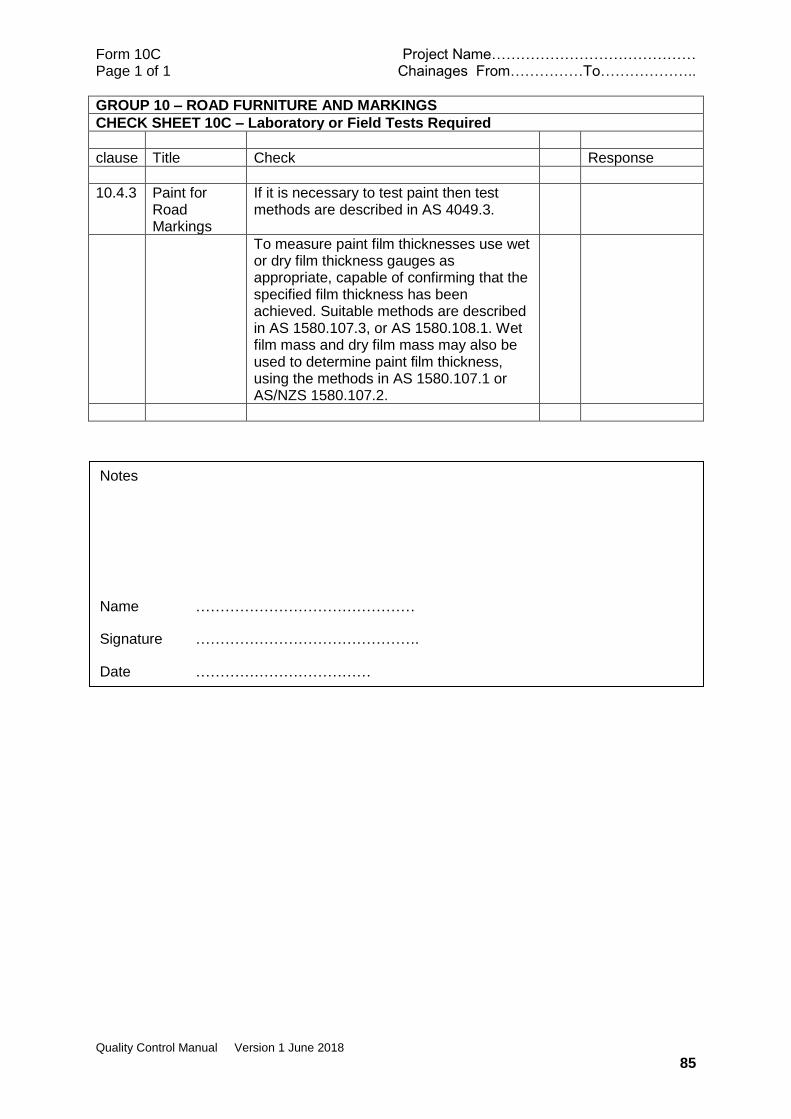
Form 10C Project Name…………………………………… Page 1 of 1 Chainages From……………To………………..
Quality Control Manual Version 1 June 2018
85
GROUP 10 – ROAD FURNITURE AND MARKINGS
CHECK SHEET 10C – Laboratory or Field Tests Required
clause Title Check Response
10.4.3 Paint for Road Markings
If it is necessary to test paint then test methods are described in AS 4049.3.
To measure paint film thicknesses use wet or dry film thickness gauges as appropriate, capable of confirming that the specified film thickness has been achieved. Suitable methods are described in AS 1580.107.3, or AS 1580.108.1. Wet film mass and dry film mass may also be used to determine paint film thickness, using the methods in AS 1580.107.1 or AS/NZS 1580.107.2.
Notes
Name ………………………………………
Signature ……………………………………….
Date ………………………………
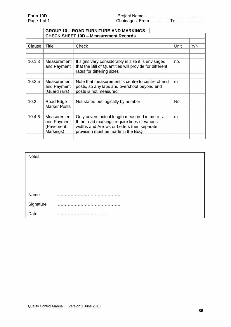
Form 10D Project Name…………………………………… Page 1 of 1 Chainages From……………To………………..
Quality Control Manual Version 1 June 2018
86
GROUP 10 – ROAD FURNITURE AND MARKINGS
CHECK SHEET 10D – Measurement Records
Clause Title Check Unit Y/N
10.1.3 Measurement and Payment
If signs vary considerably in size it is envisaged that the Bill of Quantities will provide for different rates for differing sizes
no.
10.2.5 Measurement and Payment (Guard rails)
Note that measurement is centre to centre of end posts, so any laps and overshoot beyond end posts is not measured
m
10.3 Road Edge Marker Posts
Not stated but logically by number No.
10.4.6 Measurement and Payment (Pavement Markings)
Only covers actual length measured in metres. If the road markings require lines of various widths and Arrows or Letters then separate provision must be made in the BoQ.
m
Notes
Name ………………………………………
Signature ……………………………………….
Date ………………………………

Form 11A Project Name…………………………………… Page 1 of 1 Chainages From……………To………………..
Quality Control Manual Version 1 June 2018
87
GROUP 11 – MASONARY FOR STRUCTURES
CHECK SHEET 11A - Checks Required before physical works commence
Clause Title Check Y/N Response if N Default is “issue instruction”)
11.1 Stone Pitching
Is the proposed stone sound and durable with a minimum dimension of 150 mm and a maximum of 450 mm?
11.2 Rock walling
11.2.1 General Does the proposed rock consist of sound durable stones, of not less than 0.016 cubic metres in volume, at least 150 millimetres in vertical dimension and 300 millimetres in both horizontal dimensions?
11.2.2 Cement Grouted Rock Walling
Does the proposed rock consist of sound durable stones, of not less than 0.016 cubic metres in volume, at least 150 millimetres in vertical dimension and 200 millimetres in both horizontal dimensions Note: Specified Volume is inconsistent with dimensions. It is suggested that the dimensions take precedence as it is intended that smaller sizes of stone can be used in cement grouted walls as compared to dry stone walls
Notes
Name ………………………………………
Signature ……………………………………….
Date ………………………………

Form 11B Project Name…………………………………… Page 1 of 2 Chainages From……………To………………..
Quality Control Manual Version 1 June 2018
88
GROUP 11 – MASONARY FOR STRUCTURES
CHECK SHEET 11B - Checks Require During or After Physical Works
Clause Title Check Y/N Response if N (default is “issue instruction”)
11.1 Stone Pitching
11.1.1 General Do stones have a minimum dimension of 150 mm and a maximum of 450 mm?
Are stones being roughly dressed?
11.1.2 Mortar for grouting
Does mortar for stone pitching consist of 1 part cement to two parts sand and just sufficient water to be of a workable consistency?
11.1.3 Laying Is the surface on which stones are to be placed stable, and if it is embankment fill has it been well compacted?
Is a cut off wall required and is it being constructed according to drawings or as described in this clause? Note: Cut Off Wall is required if foundation material is erodible. Minimum wall thickness 450 mm. Minimum depth not specified but 450 mm suggested. Fill trench with mortar to 60% of the maximum stone dimension. Place stones. Repeat till trench filled. Place stone pitching in tight contact with wall.
Are the stones well bedded in mortar with additional mortar trowelled to a depth of 60 percent of the maximum thickness?
Are the larger stones used as toe stones at edges or in aprons and do the stones fit together closely and present an even top surface?
Are weep holes included?
11.1.4 Cement Grouting
Is mortar being well rodded into the voids between stones to a depth of at least 75mm from the surface?
Is the grouted stone being kept damp for 48 hours after placing
11.2 Rock Walling
11.2.1 General Is the stone sound and durable, not less than 0.016 cubic metres in volume, at least 150 millimetres in vertical dimension and 300 millimetres in both horizontal dimensions? Note: smaller stones may be used for wedging.
If the wall is not founded on rock has it been bedded in a trench at least 300mm deep?

Form 11B Project Name…………………………………… Page 2 of 2 Chainages From……………To………………..
Quality Control Manual Version 1 June 2018
89
Clause Title Check Y/N Response if N (default is “issue instruction”)
11.2.1 General (continued)
Is the stone being roughly dressed and placed in courses with vertical joints staggered?
11.2.2 Cement Grouted Rock walling
Note: minimum dimension may be reduced to 200mm for cement grouted walls, and smaller packing stones can still be used
Is each layer of stone being firmly embedded in cement mortar with a gap of 25mm between stone faces? Note: Mortar is 2 parts sand to one part cement and just sufficient water to be of workable consistency
Are weep holes being included?
11.2.4 Feathering Have grouted walls been finished on top with a 25mm layer of mortar bevelled at a slope of 3:1 to drain water to the front face?
Notes
Name ………………………………………
Signature ……………………………………….
Date ………………………………

Form 11C Project Name…………………………………… Page 1 of 1 Chainages From……………To………………..
Quality Control Manual Version 1 June 2018
90
GROUP 11 – MASONARY FOR STRUCTURES
CHECK SHEET 11C – Laboratory or Field Tests Required
clause Title Check
NOT RELEVANT
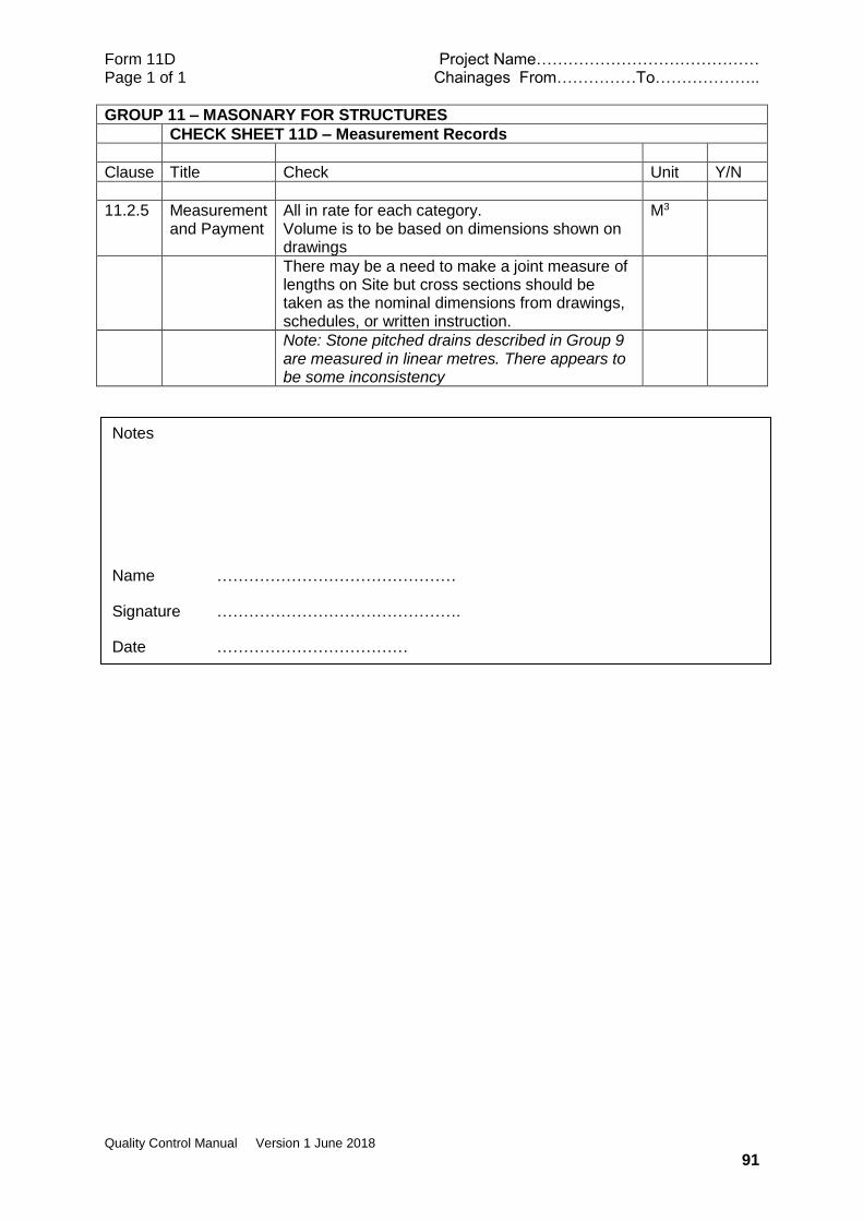
Form 11D Project Name…………………………………… Page 1 of 1 Chainages From……………To………………..
Quality Control Manual Version 1 June 2018
91
GROUP 11 – MASONARY FOR STRUCTURES
CHECK SHEET 11D – Measurement Records
Clause Title Check Unit Y/N
11.2.5 Measurement and Payment
All in rate for each category. Volume is to be based on dimensions shown on drawings
M3
There may be a need to make a joint measure of lengths on Site but cross sections should be taken as the nominal dimensions from drawings, schedules, or written instruction.
Note: Stone pitched drains described in Group 9 are measured in linear metres. There appears to be some inconsistency
Notes
Name ………………………………………
Signature ……………………………………….
Date ………………………………
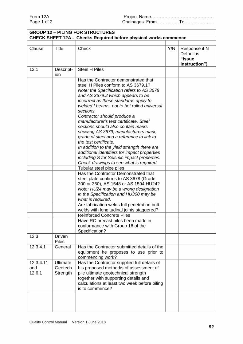
Form 12A Project Name…………………………………… Page 1 of 2 Chainages From……………To………………..
Quality Control Manual Version 1 June 2018
92
GROUP 12 – PILING FOR STRUCTURES
CHECK SHEET 12A - Checks Required before physical works commence
Clause Title Check Y/N Response if N Default is “issue instruction”)
12.1 Descript-ion
Steel H Piles
Has the Contractor demonstrated that steel H Piles conform to AS 3679.1? Note: the Specification refers to AS 3678 and AS 3679.2 which appears to be incorrect as these standards apply to welded I beams, not to hot rolled universal sections. Contractor should produce a manufacturer’s test certificate. Steel sections should also contain marks showing AS 3679; manufacturers mark, grade of steel and a reference to link to the test certificate. In addition to the yield strength there are additional identifiers for impact properties including S for Seismic impact properties. Check drawings to see what is required.
Tubular steel pipe piles
Has the Contractor Demonstrated that steel plate confirms to AS 3678 (Grade 300 or 350), AS 1548 or AS 1594 HU24? Note: HU24 may be a wrong designation in the Specification and HU300 may be what is required.
Are fabrication welds full penetration butt welds with longitudinal joints staggered?
Reinforced Concrete Piles
Have RC precast piles been made in conformance with Group 16 of the Specification?
12.3 Driven Piles
12.3.4.1 General Has the Contractor submitted details of the equipment he proposes to use prior to commencing work?
12.3.4.11 and 12.6.1
Ultimate Geotech. Strength
Has the Contractor supplied full details of his proposed method/s of assessment of pile ultimate geotechnical strength together with supporting details and calculations at least two week before piling is to commence?
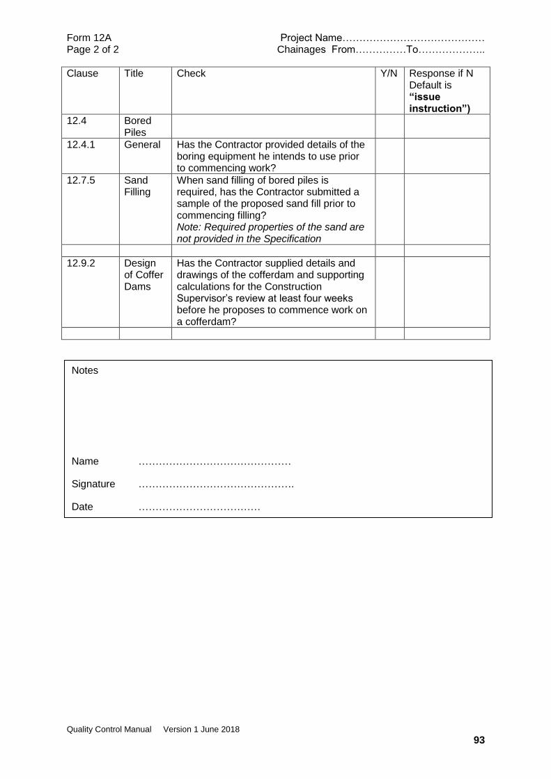
Form 12A Project Name…………………………………… Page 2 of 2 Chainages From……………To………………..
Quality Control Manual Version 1 June 2018
93
Clause Title Check Y/N Response if N Default is “issue instruction”)
12.4 Bored Piles
12.4.1 General Has the Contractor provided details of the boring equipment he intends to use prior to commencing work?
12.7.5 Sand Filling
When sand filling of bored piles is required, has the Contractor submitted a sample of the proposed sand fill prior to commencing filling? Note: Required properties of the sand are not provided in the Specification
12.9.2 Design of Coffer Dams
Has the Contractor supplied details and drawings of the cofferdam and supporting calculations for the Construction Supervisor’s review at least four weeks before he proposes to commence work on a cofferdam?
Notes
Name ………………………………………
Signature ……………………………………….
Date ………………………………

Form 12B Project Name…………………………………… Page 1of 4 Chainages From……………To………………..
Quality Control Manual Version 1 June 2018
94
GROUP 12 – PILING FOR STRUCTURES
CHECK SHEET 12B - Checks Require During or After Physical Works
In sequence of activities
Clause Title Check Y/N Response if N (default is “issue instruction”)
12.1 Description If Steel H piles are to be used, have they been approved? Note: For additional site check Steel sections should contain marks showing AS; manufacturers mark; grade of steel; and a reference link to the test certificate.
If tubular steel piles are to be used, have the piles been approved?
Do steel piles have suitable reinforced toes or shoes for driving? Note: Unless shown otherwise on drawings pile toes should be cut off square to the longitudinal axis and not protrude.
If protective coatings are required for steel piles, have these been applied in conformance with clause 18.9.4 and 18.10 of the Specification?
If RC concrete piles are to be used, have the piles been approved?
12.3 Driven Piles
12.3.2 Handling Have RC piles reached an age of 28 days since casting?
Are suitable arrangements for lifting and stacking in place?
12.3.3 Preparation for driving
Do RC piles have a driving shoe as shown on drawings?
Have piles been pitched at the correct rake?
Is a suitable pile helmet in place with adequate cushioning between the helmet and the pile?
12.3.6 Pile Driving Records
Prior to driving have the pile number and overall length been marked on it near the head by stamping into the metal or other suitable means?
Has each pile been marked legibly by painting at intervals of five hundred (500) millimetres with marks to indicate the distance from the pile toe?
12.3.4 Method of Driving
12.1 General Has the Contractor mobilised adequate pile driving equipment?
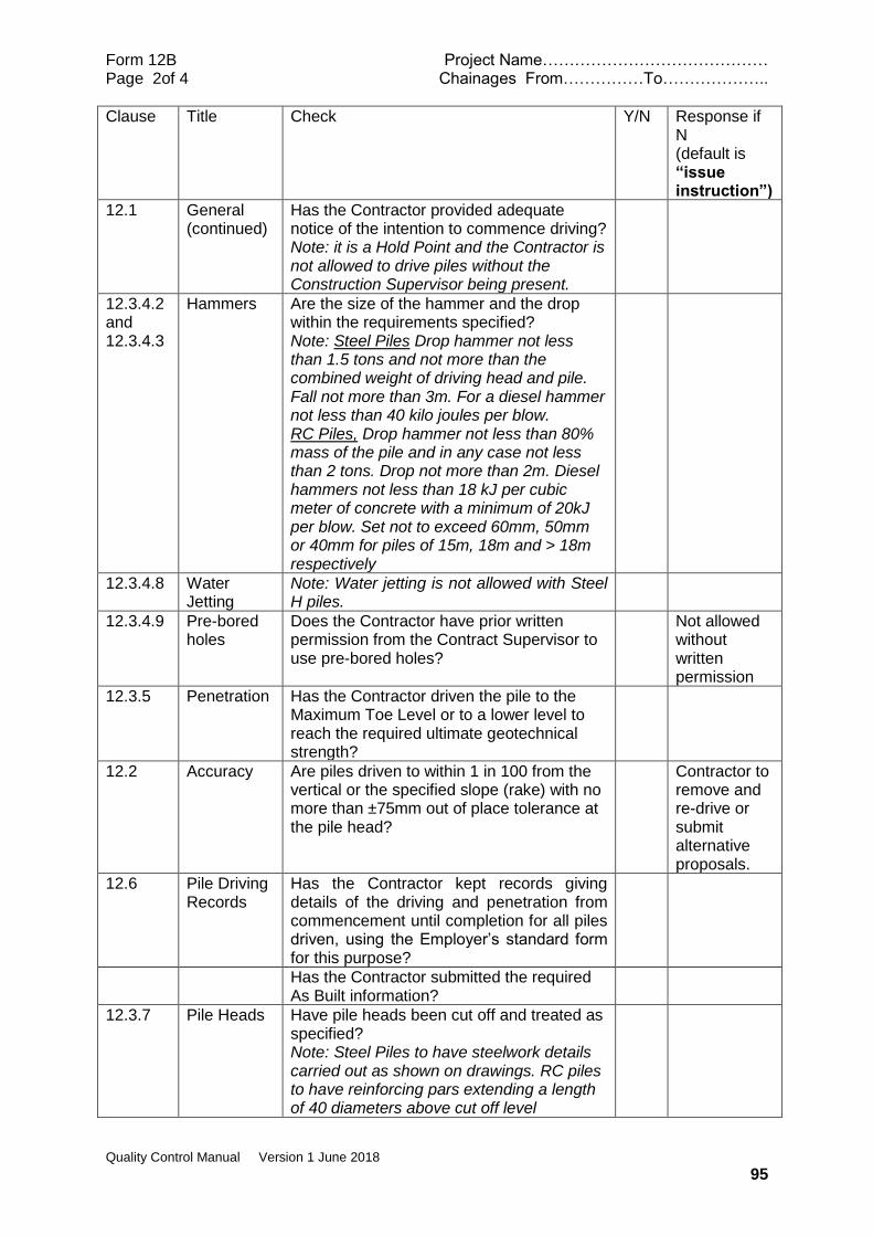
Form 12B Project Name…………………………………… Page 2of 4 Chainages From……………To………………..
Quality Control Manual Version 1 June 2018
95
Clause Title Check Y/N Response if N (default is “issue instruction”)
12.1 General (continued)
Has the Contractor provided adequate notice of the intention to commence driving? Note: it is a Hold Point and the Contractor is not allowed to drive piles without the Construction Supervisor being present.
12.3.4.2 and 12.3.4.3
Hammers Are the size of the hammer and the drop within the requirements specified? Note: Steel Piles Drop hammer not less than 1.5 tons and not more than the combined weight of driving head and pile. Fall not more than 3m. For a diesel hammer not less than 40 kilo joules per blow. RC Piles, Drop hammer not less than 80% mass of the pile and in any case not less than 2 tons. Drop not more than 2m. Diesel hammers not less than 18 kJ per cubic meter of concrete with a minimum of 20kJ per blow. Set not to exceed 60mm, 50mm or 40mm for piles of 15m, 18m and > 18m respectively
12.3.4.8 Water Jetting
Note: Water jetting is not allowed with Steel H piles.
12.3.4.9 Pre-bored holes
Does the Contractor have prior written permission from the Contract Supervisor to use pre-bored holes?
Not allowed without written permission
12.3.5 Penetration Has the Contractor driven the pile to the Maximum Toe Level or to a lower level to reach the required ultimate geotechnical strength?
12.2 Accuracy Are piles driven to within 1 in 100 from the vertical or the specified slope (rake) with no more than ±75mm out of place tolerance at the pile head?
Contractor to remove and re-drive or submit alternative proposals.
12.6 Pile Driving Records
Has the Contractor kept records giving details of the driving and penetration from commencement until completion for all piles driven, using the Employer’s standard form for this purpose?
Has the Contractor submitted the required As Built information?
12.3.7 Pile Heads Have pile heads been cut off and treated as specified? Note: Steel Piles to have steelwork details carried out as shown on drawings. RC piles to have reinforcing pars extending a length of 40 diameters above cut off level
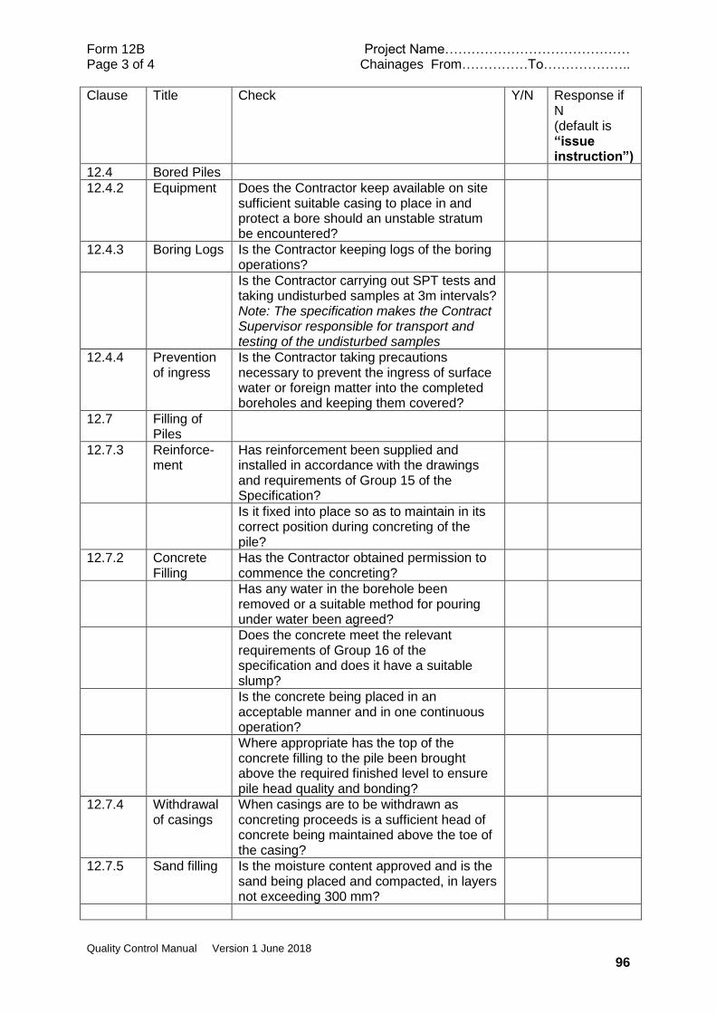
Form 12B Project Name…………………………………… Page 3 of 4 Chainages From……………To………………..
Quality Control Manual Version 1 June 2018
96
Clause Title Check Y/N Response if N (default is “issue instruction”)
12.4 Bored Piles
12.4.2 Equipment Does the Contractor keep available on site sufficient suitable casing to place in and protect a bore should an unstable stratum be encountered?
12.4.3 Boring Logs Is the Contractor keeping logs of the boring operations?
Is the Contractor carrying out SPT tests and taking undisturbed samples at 3m intervals? Note: The specification makes the Contract Supervisor responsible for transport and testing of the undisturbed samples
12.4.4 Prevention of ingress
Is the Contractor taking precautions necessary to prevent the ingress of surface water or foreign matter into the completed boreholes and keeping them covered?
12.7 Filling of Piles
12.7.3 Reinforce-ment
Has reinforcement been supplied and installed in accordance with the drawings and requirements of Group 15 of the Specification?
Is it fixed into place so as to maintain in its correct position during concreting of the pile?
12.7.2 Concrete Filling
Has the Contractor obtained permission to commence the concreting?
Has any water in the borehole been removed or a suitable method for pouring under water been agreed?
Does the concrete meet the relevant requirements of Group 16 of the specification and does it have a suitable slump?
Is the concrete being placed in an acceptable manner and in one continuous operation?
Where appropriate has the top of the concrete filling to the pile been brought above the required finished level to ensure pile head quality and bonding?
12.7.4 Withdrawal of casings
When casings are to be withdrawn as concreting proceeds is a sufficient head of concrete being maintained above the toe of the casing?
12.7.5 Sand filling Is the moisture content approved and is the sand being placed and compacted, in layers not exceeding 300 mm?

Form 12B Project Name…………………………………… Page 4 of 4 Chainages From……………To………………..
Quality Control Manual Version 1 June 2018
97
Clause Title Check Y/N Response if N (default is “issue instruction”)
12.9 Coffer Dams and Caissons
This is a Hold Point
12.9.2 Design Have the design and drawings for the coffer dam been approved in prior to work commencing?
12.9.3 Removal Have all materials and temporary islands been removed and suitably disposed of?
12.9.4 Caissons Have caissons been positioned accurately to line and level?
Notes
Name ………………………………………
Signature ……………………………………….
Date ………………………………

Form 12C Project Name…………………………………… Page 1 of 1 Chainages From……………To………………..
Quality Control Manual Version 1 June 2018
98
GROUP 12 – PILING FOR STRUCTURES
CHECK SHEET 12C – Laboratory or Field Tests Required
clause Title Check Satisfactory Test results provided?
12.1 Description Reinforced Concrete piles to be manufactured in conformance with Group 15 and 16 of the Specification.
Checks need to be made on quality control during manufacture, whether on or off the Site.
12.4.3 Bored Piles SPT testing at 3m intervals by Contractor Note: AS 1289.6.3.1
Undisturbed samples to be taken at 3m intervals by Contractor for transport and testing by Contract Supervisor Note: No tests specified and consultation with the designer may be required. Soil classification tests would be the minimum (particle size distribution, liquid and plastic limits) but shear strength testing may also be required
12.6.2 Static Load Testing
Test Method is set out in the Specification
12.7.2 Concrete filling
Slump tests and concrete cylinder tests will be required
12.7.5 Sand Filling Requirements not specified but should be a clean, well graded sand with suggested particle size limits 80% passing the 2.36 mm sieve and not more than 10% passing the .075 mm sieve.
Notes
Name ………………………………………
Signature ……………………………………….
Date ………………………………
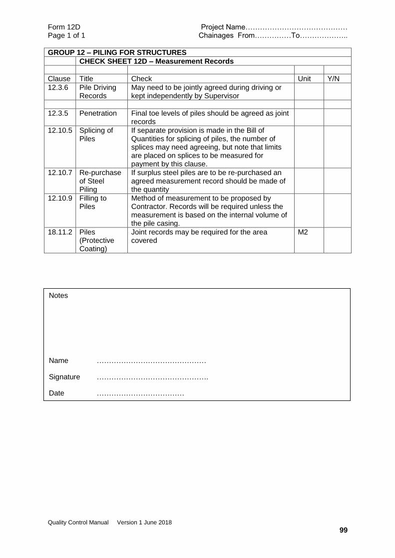
Form 12D Project Name…………………………………… Page 1 of 1 Chainages From……………To………………..
Quality Control Manual Version 1 June 2018
99
GROUP 12 – PILING FOR STRUCTURES
CHECK SHEET 12D – Measurement Records
Clause Title Check Unit Y/N
12.3.6 Pile Driving Records
May need to be jointly agreed during driving or kept independently by Supervisor
12.3.5 Penetration Final toe levels of piles should be agreed as joint records
12.10.5 Splicing of Piles
If separate provision is made in the Bill of Quantities for splicing of piles, the number of splices may need agreeing, but note that limits are placed on splices to be measured for payment by this clause.
12.10.7 Re-purchase of Steel Piling
If surplus steel piles are to be re-purchased an agreed measurement record should be made of the quantity
12.10.9 Filling to Piles
Method of measurement to be proposed by Contractor. Records will be required unless the measurement is based on the internal volume of the pile casing.
18.11.2 Piles (Protective Coating)
Joint records may be required for the area covered
M2
Notes
Name ………………………………………
Signature ……………………………………….
Date ………………………………
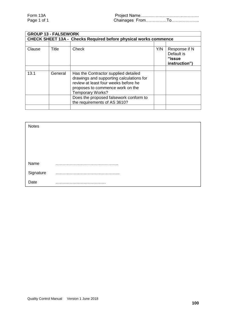
Form 13A Project Name…………………………………… Page 1 of 1 Chainages From……………To………………..
Quality Control Manual Version 1 June 2018
100
GROUP 13 - FALSEWORK
CHECK SHEET 13A - Checks Required before physical works commence
Clause Title Check Y/N Response if N Default is “issue instruction”)
13.1 General Has the Contractor supplied detailed drawings and supporting calculations for review at least four weeks before he proposes to commence work on the Temporary Works?
Does the proposed falsework conform to the requirements of AS 3610?
Notes
Name ………………………………………
Signature ……………………………………….
Date ………………………………

Form 13B Project Name…………………………………… Page 1 of 1 Chainages From……………To………………..
Quality Control Manual Version 1 June 2018
101
GROUP 13 - FALSEWORK
CHECK SHEET 13B - Checks Require During or After Physical Works
Clause Title Check Y/N Response if N (default is “issue instruction”)
13.1 General Has the Construction Supervisor provided written consent for the proposed falsework?
Is the falsework being erected in accordance with the approved design and drawings?
Is the falsework on a suitable foundation?
Has the release of falsework support to the permanent works been agreed?
Has all temporary works material been removed and the site made good to the satisfaction of the Construction Supervisor?
Notes
Name ………………………………………
Signature ……………………………………….
Date ………………………………

Form 13C Project Name…………………………………… Page 1 of 1 Chainages From……………To………………..
Quality Control Manual Version 1 June 2018
102
GROUP 13 - FALSEWORK
CHECK SHEET 13C – Laboratory or Field Tests Required
clause Title Check
NOT RELEVANT

Form 13D Project Name…………………………………… Page 1 of 1 Chainages From……………To………………..
Quality Control Manual Version 1 June 2018
103
GROUP 13 - FALSEWORK
CHECK SHEET 13D – Measurement Records
Clause Title Check Unit Y/N
Contractor responsibility to cover costs of temporary works in other rates
Photographic Records would be useful
Notes
Name ………………………………………
Signature ……………………………………….
Date ………………………………
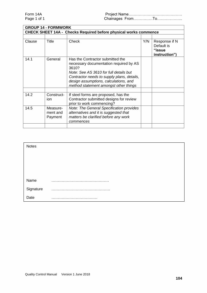
Form 14A Project Name…………………………………… Page 1 of 1 Chainages From……………To………………..
Quality Control Manual Version 1 June 2018
104
GROUP 14 - FORMWORK
CHECK SHEET 14A - Checks Required before physical works commence
Clause Title Check Y/N Response if N Default is “issue instruction”)
14.1 General Has the Contractor submitted the necessary documentation required by AS 3610? Note: See AS 3610 for full details but Contractor needs to supply plans, details, design assumptions, calculations, and method statement amongst other things
14.2 Construct-ion
If steel forms are proposed, has the Contractor submitted designs for review prior to work commencing?
14.5 Measure-ment and Payment
Note: The General Specification provides alternatives and it is suggested that matters be clarified before any work commences
Notes
Name ………………………………………
Signature ……………………………………….
Date ………………………………
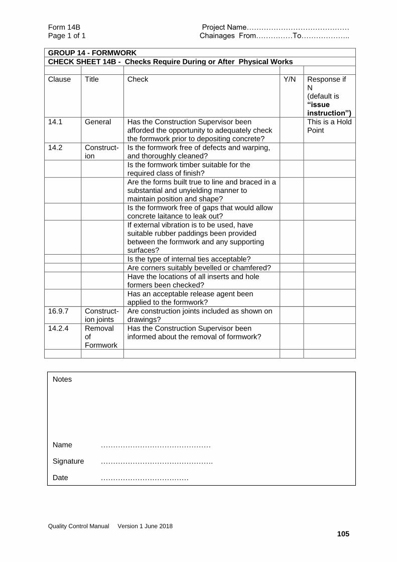
Form 14B Project Name…………………………………… Page 1 of 1 Chainages From……………To………………..
Quality Control Manual Version 1 June 2018
105
GROUP 14 - FORMWORK
CHECK SHEET 14B - Checks Require During or After Physical Works
Clause Title Check Y/N Response if N (default is “issue instruction”)
14.1 General Has the Construction Supervisor been afforded the opportunity to adequately check the formwork prior to depositing concrete?
This is a Hold Point
14.2 Construct-ion
Is the formwork free of defects and warping, and thoroughly cleaned?
Is the formwork timber suitable for the required class of finish?
Are the forms built true to line and braced in a substantial and unyielding manner to maintain position and shape?
Is the formwork free of gaps that would allow concrete laitance to leak out?
If external vibration is to be used, have suitable rubber paddings been provided between the formwork and any supporting surfaces?
Is the type of internal ties acceptable?
Are corners suitably bevelled or chamfered?
Have the locations of all inserts and hole formers been checked?
Has an acceptable release agent been applied to the formwork?
16.9.7 Construct-ion joints
Are construction joints included as shown on drawings?
14.2.4 Removal of Formwork
Has the Construction Supervisor been informed about the removal of formwork?
Notes
Name ………………………………………
Signature ……………………………………….
Date ………………………………

Form 14C Project Name…………………………………… Page 1 of 1 Chainages From……………To………………..
Quality Control Manual Version 1 June 2018
106
GROUP 14 - FORMWORK
CHECK SHEET 14C – Laboratory or Field Tests Required
clause Title Check
NOT RELEVANT
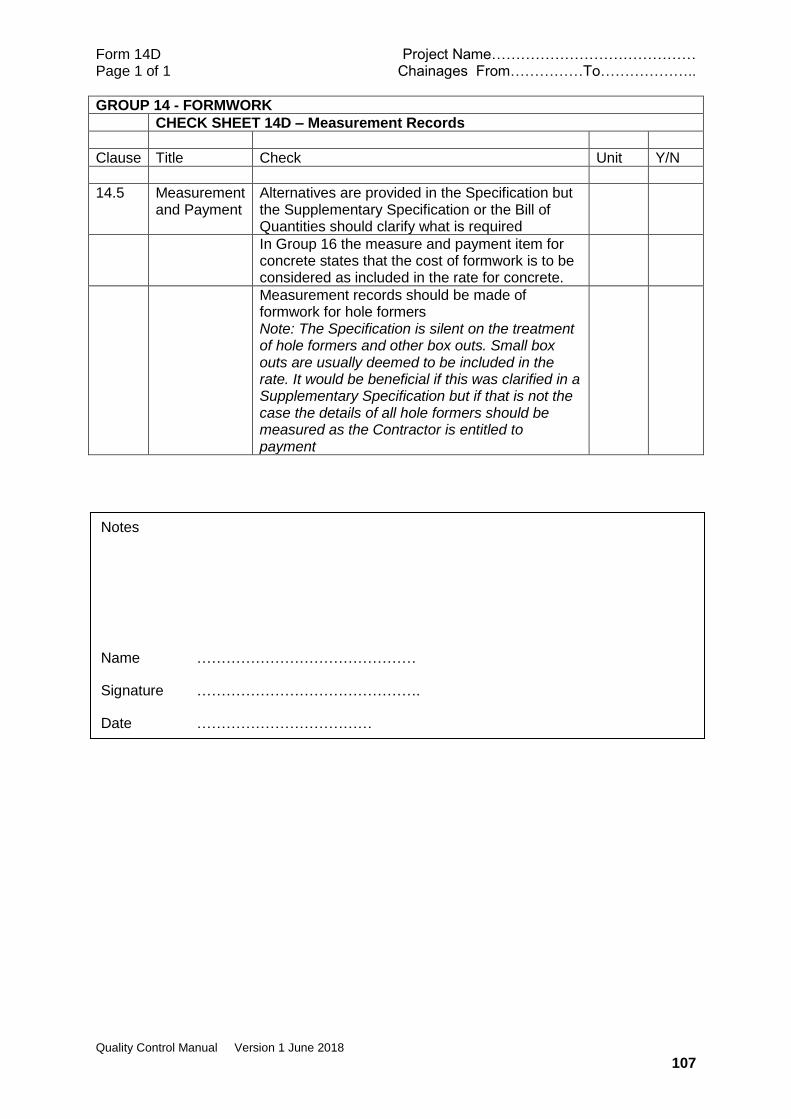
Form 14D Project Name…………………………………… Page 1 of 1 Chainages From……………To………………..
Quality Control Manual Version 1 June 2018
107
GROUP 14 - FORMWORK
CHECK SHEET 14D – Measurement Records
Clause Title Check Unit Y/N
14.5 Measurement and Payment
Alternatives are provided in the Specification but the Supplementary Specification or the Bill of Quantities should clarify what is required
In Group 16 the measure and payment item for concrete states that the cost of formwork is to be considered as included in the rate for concrete.
Measurement records should be made of formwork for hole formers Note: The Specification is silent on the treatment of hole formers and other box outs. Small box outs are usually deemed to be included in the rate. It would be beneficial if this was clarified in a Supplementary Specification but if that is not the case the details of all hole formers should be measured as the Contractor is entitled to payment
Notes
Name ………………………………………
Signature ……………………………………….
Date ………………………………

Form 15A Project Name…………………………………… Page 1 of 1 Chainages From……………To………………..
Quality Control Manual Version 1 June 2018
108
GROUP 15 STEEL REINFORCEMENT
CHECK SHEET 15A - Checks Required before physical works commence
Clause Title Check Y/N Response if N Default is “issue instruction”)
15.2 Materials Has the Contractor provided an acceptable Manufacturer’s test certificate for the reinforcement proposed for use three weeks prior to planned commencement of steel fixing?
If the Contractor has not provided an acceptable test certificate, has the Contractor provided the appropriate number of test pieces at least 3 weeks prior to planned commencement of steel fixing? Note: one test piece for each 5 tonnes of steel reinforcement to be used with a minimum of 2 test pieces from each bar size
If the Contractor wishes to substitute an equivalent fabric to replace placed bars shown on drawings, has he submitted a detailed proposal with satisfactory supporting evidence?
15.4 Cutting and Bending
Has the Contractor submitted a Reinforcement Bending Schedule showing bar mark, shape code (AS 1100.501), bent lengths, cut length and weights at least three weeks prior to the commencement of cutting and bending of reinforcement?
Notes
Name ………………………………………
Signature ……………………………………….
Date ………………………………
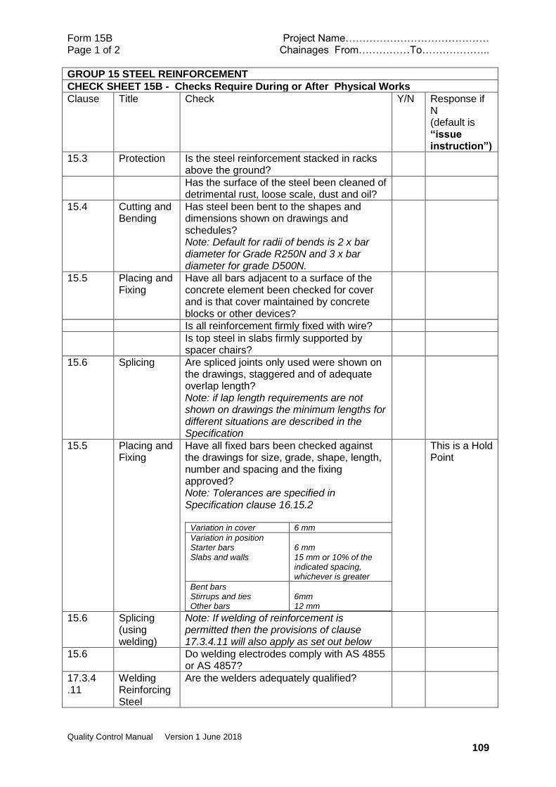
Form 15B Project Name…………………………………… Page 1 of 2 Chainages From……………To………………..
Quality Control Manual Version 1 June 2018
109
GROUP 15 STEEL REINFORCEMENT
CHECK SHEET 15B - Checks Require During or After Physical Works
Clause Title Check Y/N Response if N (default is “issue instruction”)
15.3 Protection Is the steel reinforcement stacked in racks above the ground?
Has the surface of the steel been cleaned of detrimental rust, loose scale, dust and oil?
15.4 Cutting and Bending
Has steel been bent to the shapes and dimensions shown on drawings and schedules? Note: Default for radii of bends is 2 x bar diameter for Grade R250N and 3 x bar diameter for grade D500N.
15.5 Placing and Fixing
Have all bars adjacent to a surface of the concrete element been checked for cover and is that cover maintained by concrete blocks or other devices?
Is all reinforcement firmly fixed with wire?
Is top steel in slabs firmly supported by spacer chairs?
15.6 Splicing Are spliced joints only used were shown on the drawings, staggered and of adequate overlap length? Note: if lap length requirements are not shown on drawings the minimum lengths for different situations are described in the Specification
15.5 Placing and Fixing
Have all fixed bars been checked against the drawings for size, grade, shape, length, number and spacing and the fixing approved? Note: Tolerances are specified in Specification clause 16.15.2
Variation in cover 6 mm
Variation in position Starter bars Slabs and walls
6 mm 15 mm or 10% of the indicated spacing, whichever is greater
Bent bars Stirrups and ties Other bars
6mm 12 mm
This is a Hold Point
15.6 Splicing (using welding)
Note: If welding of reinforcement is permitted then the provisions of clause 17.3.4.11 will also apply as set out below
15.6 Do welding electrodes comply with AS 4855 or AS 4857?
17.3.4 .11
Welding Reinforcing Steel
Are the welders adequately qualified?
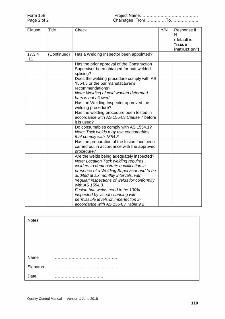
Form 15B Project Name…………………………………… Page 2 of 2 Chainages From……………To………………..
Quality Control Manual Version 1 June 2018
110
Clause Title Check Y/N Response if N (default is “issue instruction”)
17.3.4 .11
(Continued) Has a Welding Inspector been appointed?
Has the prior approval of the Construction Supervisor been obtained for butt welded splicing?
Does the welding procedure comply with AS 1554.3 or the bar manufacturer’s recommendations? Note: Welding of cold worked deformed bars is not allowed
Has the Welding Inspector approved the welding procedure?
Has the welding procedure been tested in accordance with AS 1554.3 Clause 7 before it is used?
Do consumables comply with AS 1554.1? Note: Tack welds may use consumables that comply with 1554.3
Has the preparation of the fusion face been carried out in accordance with the approved procedure?
Are the welds being adequately inspected? Note: Location Tack welding requires welders to demonstrate qualification in presence of a Welding Supervisor and to be audited at six monthly intervals, with ‘regular’ inspections of welds for conformity with AS 1554.3. Fusion butt welds need to be 100% inspected by visual scanning with permissible levels of imperfection in accordance with AS 1554.3 Table 9.2
Notes
Name ………………………………………
Signature ……………………………………….
Date ………………………………

Form 15C Project Name…………………………………… Page 1 of 1 Chainages From……………To………………..
Quality Control Manual Version 1 June 2018
111
GROUP 15 STEEL REINFORCEMENT
CHECK SHEET 15C – Laboratory or Field Tests Required
clause Title Check Response
15.2 Materials If a manufacturer’s test certificate is not provided then tests will be needed as described in Appendix C of AS 4671
Notes
Name ………………………………………
Signature ……………………………………….
Date ………………………………

Form 15D Project Name…………………………………… Page 1 of 1 Chainages From……………To………………..
Quality Control Manual Version 1 June 2018
112
GROUP 15 STEEL REINFORCEMENT
CHECK SHEET 15D – Measurement Records
Clause Title Check Unit Y/N
15.9 Measurement and Payment
Reinforcing bars measured in tons with spliced joints shown on drawings included in the measured quantity. Additional spliced joints agreed for the benefit of the Contractor are not measured. Note: Bending schedules should provide a reliable means of measure
ton
Mesh is measured in square meters placed but the measured quantity is to exclude the laps
M2
Notes
Name ………………………………………
Signature ……………………………………….
Date ………………………………
Form 16A Project Name…………………………………… Page 1 of 2 Chainages From……………To………………..
Quality Control Manual Version 1 June 2018
113
GROUP 16 – CONCRETE FOR STRUCTURES
CHECK SHEET 16A - Checks Required before physical works commence
Clause Title Check Y/N Response if N Default is “issue instruction”
16.5 Materials
16.4 Inspection Has the Contractor provided 48 hours’ notice of his intention to pour concrete?
16.5.6 Testing Has the Contractor provided 50kg of course aggregate and 25kg of fine aggregate for testing by the Construction Supervisor? Note: Notice period for the delivery of aggregates not provided but samples have to be tested for conformance with AS 2758.1 before they can be used which will take several days
It is a Hold Point that aggregates shall be approved in writing prior to being used.
16.6 Concrete Proportions and Design
16.6.2 Grouts Has the Contractor provided details of the proposed mix design (for grout) and 6 standard test specimens?
16.6.3 General Has the Contractor provided details of the concrete mix he proposes to use for each particular Grade of concrete for prior approval? Note: refer to Specification clause 16.6.3 for details required.
16.6.4 Preliminary Mixes
Has the Contractor made preliminary mixes of Grades 40, 30, 25, 20 and 15 concrete, using the approved materials, under closely controlled laboratory conditions in the presence of the Construction Supervisor?
Has the Contractor made nine cylinders from each preliminary mix and tested them as described? Note: 3 tested at 7 days and 6 tested at 28 days.
Have the preliminary mixes been approved?
16.8.2 Ready Mixed Concrete
Has the Contractor obtained prior approval for any intended supplier of Ready Mixed Concrete?

Form 16A Project Name…………………………………… Page 1 of 2 Chainages From……………To………………..
Quality Control Manual Version 1 June 2018
114
16.9.1 Program Has the Contractor submitted a program detailing the sequence and timing of all concrete pours and curing periods for a structure, 7days prior to planned commencement?
Notes
Name ………………………………………
Signature ……………………………………….
Date ………………………………
Form 16B Project Name…………………………………… Page 1 of 4 Chainages From……………To………………..
Quality Control Manual Version 1 June 2018
115
GROUP 16 – CONCRETE FOR STRUCTURES
CHECK SHEET 16B - Checks Require During or After Physical Works
Clause Title Check Y/N Response if N (default is “issue instruction”)
16.4 Inspection Has the underlying ground condition been approved (under Group 4 of the Specification) prior to placing any blinding concrete?
16.5 Materials
16.5.2 Cement Is the cement Ordinary Portland Cement Type GP (General Purpose) that complies with AS 3972? Note: Manufacturer’s certificate may be required unless brand is well known
Has the Contractor obtained written permission if he intends to use cement other than Ordinary Portland Cement Type GP Note: Other types of cement not allowed without written permission
16.5.7 Storage Is cement being stored above ground level in weatherproof sheds?
Can any lumps of cement that are present be broken by applying only finger pressure?
Cement not to be used
16.5.3 Water Is the water for the concrete clean and free of salts?
Test method?
16.5.4 Fine Aggregate
Has the sand been tested and approved?
If the source of sand is beach sand has it been stockpiled and thoroughly washed prior to use?
16.5.5 Course Aggregates
Has the course aggregate been tested and approved?
Is the size of the course aggregate size compatible with the use of the concrete? Note: 40mm for mass concrete, 20mm for reinforced concrete and 10mm for plinths
16.5.7 Storage Are aggregates stored on well drained concrete slabs?
15.5.8 Admixtures Have admixtures in concrete been given prior approval?
16.6.4 Preliminary Mixes
Have the preliminary mixes been approved?
16.7 Control of Concrete Quality
16.7.1 General Is the Contractor sampling the concrete and preparing an adequate number of test cylinders as required?
Form 16B Project Name…………………………………… Page 2 of 4 Chainages From……………To………………..
Quality Control Manual Version 1 June 2018
116
Clause Title Check Y/N Response if N (default is “issue instruction”)
16.7.2 Sampling and Testing
Is the Contractor sampling and testing in accordance with appropriate parts of AS 1012? Note: It is considered that the relevant parts are 1012.1 Sampling of Concrete 1012.3.1 Slump Test 1012.8.1 Compression and Indirect tensile test specimens 1012.9 Compressive Strength Tests one sample of 2 cylinders per 15m3 concrete for testing at 28 days (but with a minimum of 2 samples of 2 cylinders per casting day) For initial use of trial mix, one additional cylinder a day for the first 6 days to be tested at 7 days.
16.8 Batching and Mixing
16.8.1 On Site Is site batched concrete being prepared by weigh batching and mixed using an approved type of mixer rotating at the correct speed?
Is the minimum mixing time after all materials have been added 2 minutes?
Is the mix being placed within 45 minutes of charging the mixer? Note: if temperature is more than 32 oC then time for placing to be reduced to 30 minutes
Is weighing equipment used for batching concrete in accordance with the requirements of AS 1379? Note: The main requirement is the need for a calibration certificate less than 6 months old
16.8.2 Ready Mixed Concrete
Has the concrete temperature been checked and the concrete found acceptable for pouring? Note:
Concrete
temperature at
time of placing
Maximum elapsed
time from charging
of mixer
<32°C
32°C - 35°C
>35°C
60 minutes
45 minutes
Not Acceptable
No concrete to be used if temperature >35 oC (unless retarder has been added in which case discretion is allowed)

Form 16B Project Name…………………………………… Page 3 of 4 Chainages From……………To………………..
Quality Control Manual Version 1 June 2018
117
Clause Title Check Y/N Response if N (default is “issue instruction”)
16.9 Placing and Compacting
16.9.2 Placing Have formwork and reinforcement been checked and approved prior to placing concrete?
This is a Hold Point
Are chutes made of metal or metal lined and clean?
Is concrete being placed in a continuous manner?
Is the maximum concrete drop less than 2 m?
Vertical pipe to be used
16.9.3 Placing Concrete under water
Has prior approval been obtained for placing concrete under water?
Has the mix been adjusted to increase the cement content by 25%?
Is a tremie being used in such a manner that the concrete does not come into contact with water?
16.9.5 Compaction of Concrete
Is there one vibrator of an approved type for every 5m3 of concrete to be poured but with a minimum of 2?
Is at least one vibrator available as a reserve?
Are vibrators being inserted not more than 500mm apart?
Are vibrators being inserted so as to penetrate previously placed layers and vibration continued until air bubble cease to appear?
Are vibrators withdrawn slowly with an insertion period of at least 7 seconds but without over vibration causing segregation?
16.9.6 Concrete for Bridge Decks
Is concrete in bridge decks being poured in approximately 2m wide strips transverse to the girders?
16.11.3 Finishing Bridge decks
Have bridge decks been finished by hand screeding and power floating to the correct levels?
Has the deck been finished by brooming transversely to a rough surface?
16.11.4 Curing Are slabs being cured for 14 days and other elements for 7 days? Note: Adequate procedures for curing are an essential part of good concrete. The intention is to keep the concrete fully saturated during the curing period.
Form 16B Project Name…………………………………… Page 4 of 4 Chainages From……………To………………..
Quality Control Manual Version 1 June 2018
118
Clause Title Check Y/N Response if N (default is “issue instruction”)
Has a membrane curing compound conforming to AS 3799 been approved for use?
16.12 Bituminous Paint to Concrete Surfaces
If bituminous paint is required to concrete surfaces (e.g. earth retaining walls) has the type of paint been approved and is it being applied in accordance with the manufacturer’s recommendations?
16.13 No Fines Concrete
If no fines concrete is shown on the drawings is it being constructed according to the information on the drawings and/or the requirements of clause 16.13 of the specification?
16.14 Tolerances Do the final surfaces of concrete structures comply with the specified tolerances? Note:
Variations from vertical plumb
6mm in 3m plus 2mm, with a maximum limit of 20mm
Variations in location of sleeves and block outs
6mm
Variations in X-section dimensions of columns and beam
Minus 6mm Plus 12mm
Footings Variation of dimensions on plan Misplacement of eccentricity Reduction in thickness
Minus 12mm 2% of width with a maximum of 50 mm 5% of specified thickness
Notes
Name ………………………………………
Signature ……………………………………….
Date ………………………………
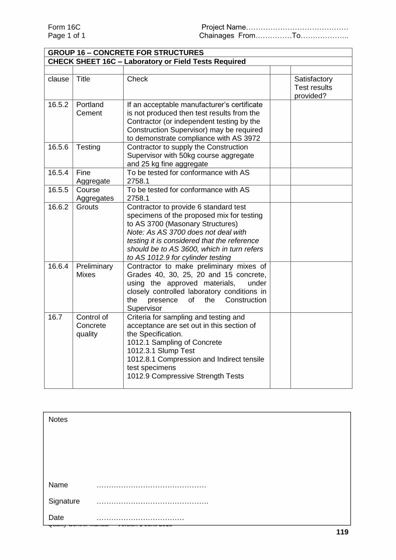
Form 16C Project Name…………………………………… Page 1 of 1 Chainages From……………To………………..
Quality Control Manual Version 1 June 2018
119
GROUP 16 – CONCRETE FOR STRUCTURES
CHECK SHEET 16C – Laboratory or Field Tests Required
clause Title Check Satisfactory Test results provided?
16.5.2 Portland Cement
If an acceptable manufacturer’s certificate is not produced then test results from the Contractor (or independent testing by the Construction Supervisor) may be required to demonstrate compliance with AS 3972
16.5.6 Testing Contractor to supply the Construction Supervisor with 50kg course aggregate and 25 kg fine aggregate
16.5.4 Fine Aggregate
To be tested for conformance with AS 2758.1
16.5.5 Course Aggregates
To be tested for conformance with AS 2758.1
16.6.2 Grouts Contractor to provide 6 standard test specimens of the proposed mix for testing to AS 3700 (Masonary Structures) Note: As AS 3700 does not deal with testing it is considered that the reference should be to AS 3600, which in turn refers to AS 1012.9 for cylinder testing
16.6.4
Preliminary Mixes
Contractor to make preliminary mixes of Grades 40, 30, 25, 20 and 15 concrete, using the approved materials, under closely controlled laboratory conditions in the presence of the Construction Supervisor
16.7 Control of Concrete quality
Criteria for sampling and testing and acceptance are set out in this section of the Specification. 1012.1 Sampling of Concrete 1012.3.1 Slump Test 1012.8.1 Compression and Indirect tensile test specimens 1012.9 Compressive Strength Tests
Notes
Name ………………………………………
Signature ……………………………………….
Date ………………………………
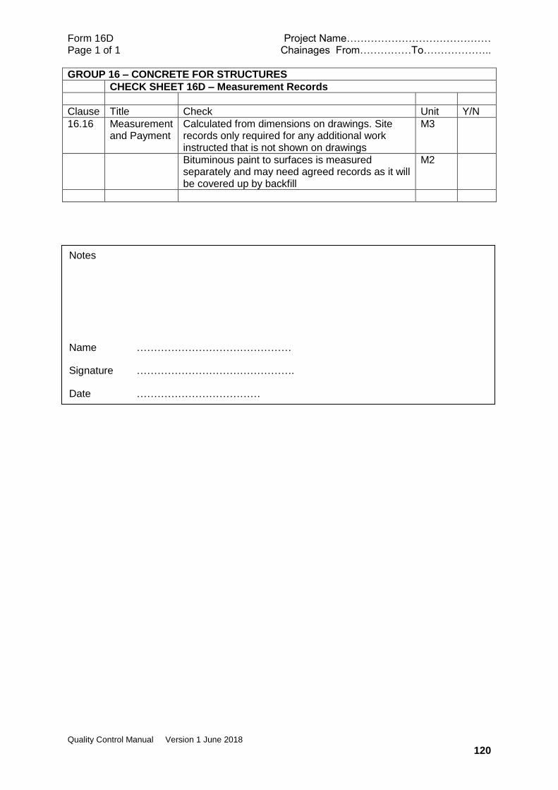
Form 16D Project Name…………………………………… Page 1 of 1 Chainages From……………To………………..
Quality Control Manual Version 1 June 2018
120
GROUP 16 – CONCRETE FOR STRUCTURES
CHECK SHEET 16D – Measurement Records
Clause Title Check Unit Y/N
16.16 Measurement and Payment
Calculated from dimensions on drawings. Site records only required for any additional work instructed that is not shown on drawings
M3
Bituminous paint to surfaces is measured separately and may need agreed records as it will be covered up by backfill
M2
Notes
Name ………………………………………
Signature ……………………………………….
Date ………………………………

Form 17A Project Name…………………………………… Page 1 of 3 Chainages From……………To………………..
Quality Control Manual Version 1 June 2018
121
GROUP 17 – STRUCTURAL STEELWORK
CHECK SHEET 17A - Checks Required before physical works commence
Clause Title Check Y/N Response if N Default is “issue instruction”)
17.1.3 Notice of Intention to Commence Work
Has the Contractor advised where the steelwork will be fabricated at least 6 weeks prior to the planned commencement of fabrication? Note: The Specification does not stipulate the time in which the Construction Supervisor has to respond but given the requirement of 17.1.4 and 17.1.1 below a maximum period of 14 days would appear necessary
17.1.4 Sub-Contractors
Has the Construction Supervisor given written approval for any proposed sub-contractor for the fabrication work?
This is a Hold Point
17.1.3 Notice of Intention to Commence Work
Has the date for commencement of fabrication been confirmed 7 days prior to commencement?
17.1.1 Drawings, Procedures and Program
Has the Contractor, at least 1 month prior to commencing any fabrication, submitted three copies of the relevant Workshop Drawings to the Construction Supervisor for review? Note: These Drawings shall clearly show all sizes, dimensions, markings and connections including loose packs, and shall set out the position sizes and length of all welds, nuts, bolts and washers as are necessary for the complete fabrication, assembly and erection of the steelwork. The Specification does not make this a Hold Point. The Specification does not give a time for a response but it is considered that this needs to be within a period of 14 days from receipt.
Has the Contractor submitted for review, fourteen (14) days before the commencement of fabrication, his complete program of work, including details of procedures entailing weld sequences, distortion control, preheating Note: The Specification does not make this a Hold Point
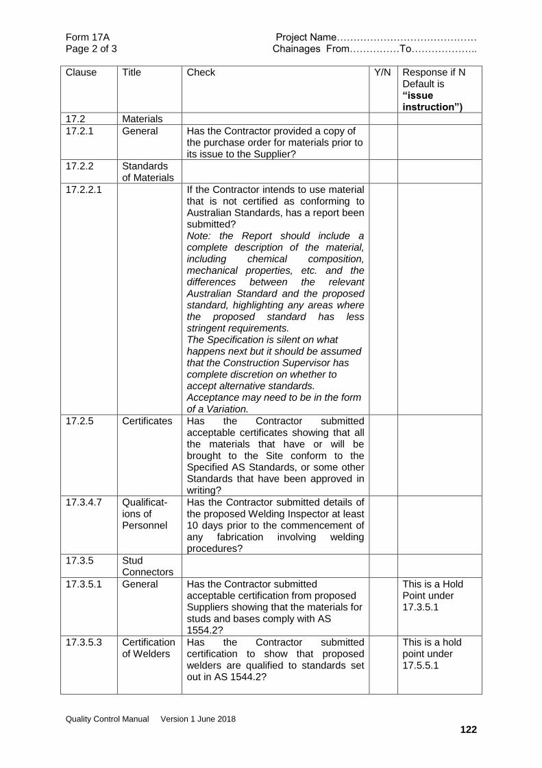
Form 17A Project Name…………………………………… Page 2 of 3 Chainages From……………To………………..
Quality Control Manual Version 1 June 2018
122
Clause Title Check Y/N Response if N Default is “issue instruction”)
17.2 Materials
17.2.1 General Has the Contractor provided a copy of the purchase order for materials prior to its issue to the Supplier?
17.2.2 Standards of Materials
17.2.2.1 If the Contractor intends to use material that is not certified as conforming to Australian Standards, has a report been submitted? Note: the Report should include a complete description of the material, including chemical composition, mechanical properties, etc. and the differences between the relevant Australian Standard and the proposed standard, highlighting any areas where the proposed standard has less stringent requirements. The Specification is silent on what happens next but it should be assumed that the Construction Supervisor has complete discretion on whether to accept alternative standards. Acceptance may need to be in the form of a Variation.
17.2.5 Certificates Has the Contractor submitted acceptable certificates showing that all the materials that have or will be brought to the Site conform to the Specified AS Standards, or some other Standards that have been approved in writing?
17.3.4.7 Qualificat-ions of Personnel
Has the Contractor submitted details of the proposed Welding Inspector at least 10 days prior to the commencement of any fabrication involving welding procedures?
17.3.5 Stud Connectors
17.3.5.1 General Has the Contractor submitted acceptable certification from proposed Suppliers showing that the materials for studs and bases comply with AS 1554.2?
This is a Hold Point under 17.3.5.1
17.3.5.3 Certification of Welders
Has the Contractor submitted certification to show that proposed welders are qualified to standards set out in AS 1544.2?
This is a hold point under 17.5.5.1
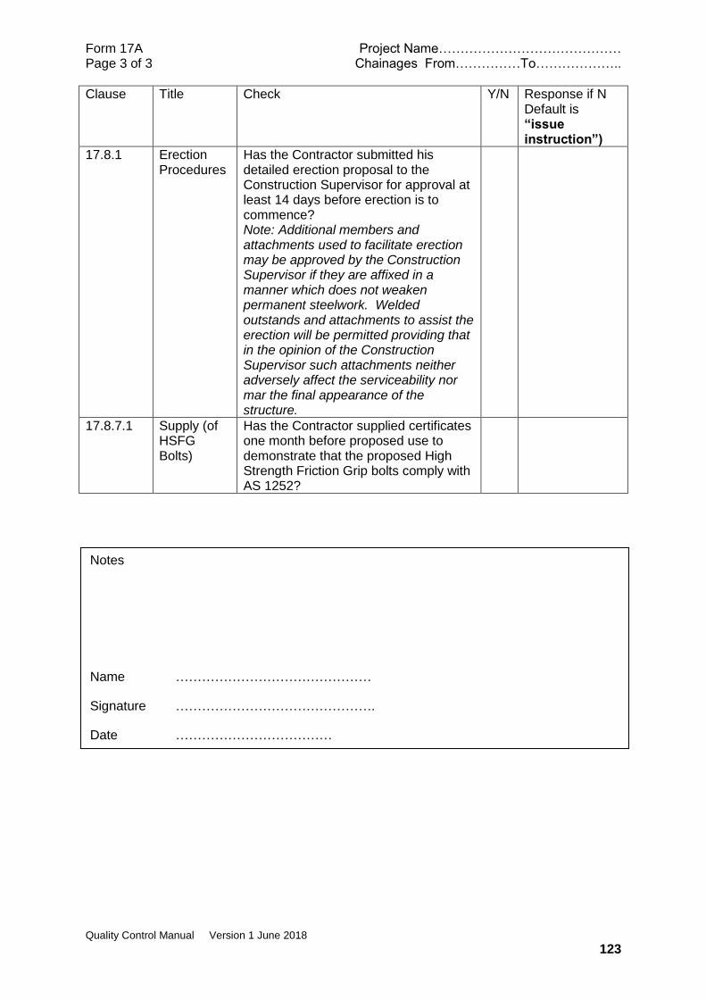
Form 17A Project Name…………………………………… Page 3 of 3 Chainages From……………To………………..
Quality Control Manual Version 1 June 2018
123
Clause Title Check Y/N Response if N Default is “issue instruction”)
17.8.1 Erection Procedures
Has the Contractor submitted his detailed erection proposal to the Construction Supervisor for approval at least 14 days before erection is to commence? Note: Additional members and attachments used to facilitate erection may be approved by the Construction Supervisor if they are affixed in a manner which does not weaken permanent steelwork. Welded outstands and attachments to assist the erection will be permitted providing that in the opinion of the Construction Supervisor such attachments neither adversely affect the serviceability nor mar the final appearance of the structure.
17.8.7.1 Supply (of HSFG Bolts)
Has the Contractor supplied certificates one month before proposed use to demonstrate that the proposed High Strength Friction Grip bolts comply with AS 1252?
Notes
Name ………………………………………
Signature ……………………………………….
Date ………………………………
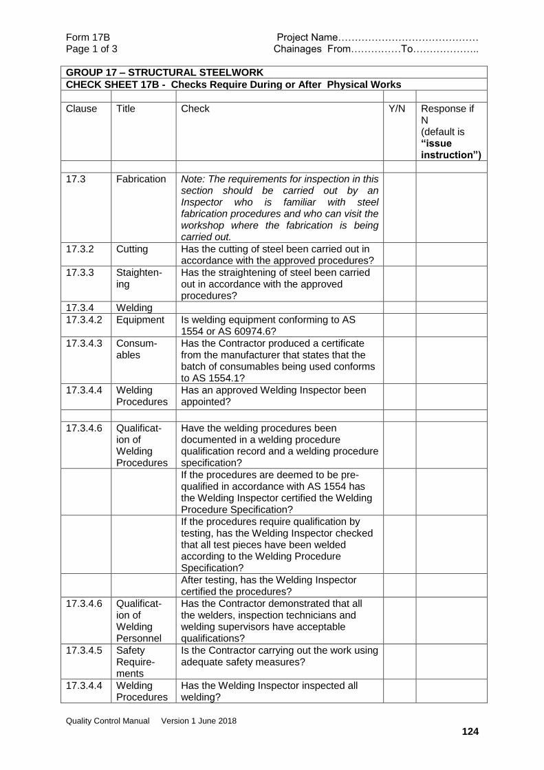
Form 17B Project Name…………………………………… Page 1 of 3 Chainages From……………To………………..
Quality Control Manual Version 1 June 2018
124
GROUP 17 – STRUCTURAL STEELWORK
CHECK SHEET 17B - Checks Require During or After Physical Works
Clause Title Check Y/N Response if N (default is “issue instruction”)
17.3 Fabrication Note: The requirements for inspection in this section should be carried out by an Inspector who is familiar with steel fabrication procedures and who can visit the workshop where the fabrication is being carried out.
17.3.2 Cutting Has the cutting of steel been carried out in accordance with the approved procedures?
17.3.3 Staighten-ing
Has the straightening of steel been carried out in accordance with the approved procedures?
17.3.4 Welding
17.3.4.2 Equipment Is welding equipment conforming to AS 1554 or AS 60974.6?
17.3.4.3 Consum-ables
Has the Contractor produced a certificate from the manufacturer that states that the batch of consumables being used conforms to AS 1554.1?
17.3.4.4 Welding Procedures
Has an approved Welding Inspector been appointed?
17.3.4.6 Qualificat-ion of Welding Procedures
Have the welding procedures been documented in a welding procedure qualification record and a welding procedure specification?
If the procedures are deemed to be pre-qualified in accordance with AS 1554 has the Welding Inspector certified the Welding Procedure Specification?
If the procedures require qualification by testing, has the Welding Inspector checked that all test pieces have been welded according to the Welding Procedure Specification?
After testing, has the Welding Inspector certified the procedures?
17.3.4.6 Qualificat-ion of Welding Personnel
Has the Contractor demonstrated that all the welders, inspection technicians and welding supervisors have acceptable qualifications?
17.3.4.5 Safety Require-ments
Is the Contractor carrying out the work using adequate safety measures?
17.3.4.4 Welding Procedures
Has the Welding Inspector inspected all welding?

Form 17B Project Name…………………………………… Page 2 of 3 Chainages From……………To………………..
Quality Control Manual Version 1 June 2018
125
Clause Title Check Y/N Response if N Default is “issue instruction”
17.3.4.9 Inspection of Welds
Are welds being inspected in accordance with methods nominated in AS 1554.1 and the requirements of clause 17.3.4.9 of the Specification?
17.3.4 .11
Welding of Reinforcing Steel
Note: Requirements under this section have been covered in Group 15 of the manual
17.3.5.1 Shear Connectors
Has material and welder certification been provided and accepted?
This is a Hold Point
17.3.5.4 Testing of Finished Stud Welds
Has every stud been tested by ring testing and, if necessary, bend testing as specified?
Have studs that failed the tests been satisfactorily repaired?
17.3.6 Holes for bolts
Are all holes being formed by drilling, with any burrs and defects removed? Note: Punching is not allowed
Are reamed and fitted holes being prepared using templates and pilot drilling to 3mm less than final size?
Are final hole sizes 2mm larger than the bolt size? Note: The inner plies of a structural connection fastened by high-strength (friction grip) bolts may have a diameter not be more than 3 mm larger than the nominal diameter of the bolt.
17.3.7 Marking Are all parts carefully marked to facilitate final assembly?
17.4 Trial Assembly
Have trial assemblies been carried out as required in the presence of the Construction Supervisor?
17.5 Tolerances Has all fabrication work been carried out to tolerances shown on the drawings or otherwise in accordance with AS 4100 Clause 14.4?
17.7 Delivery to Site
Have all parts been inspected and passed prior to leaving the Contractor’s workshop for delivery to Site?
This is a Hold Point
Are all components adequately protected from damage during delivery?
17.8 Erection
17.8.1 and 17.8.2
Erection Procedures and Additional Members
Has the Contractor’s proposed erection procedures been submitted and approved?
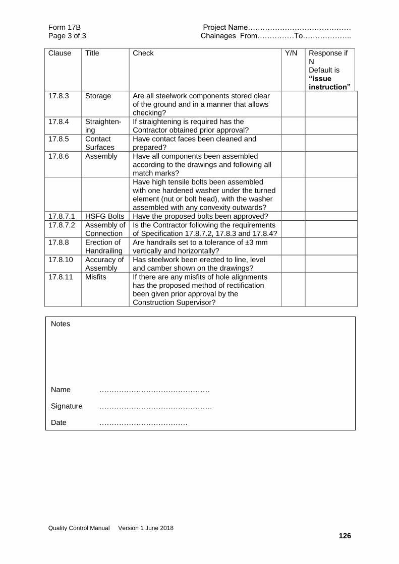
Form 17B Project Name…………………………………… Page 3 of 3 Chainages From……………To………………..
Quality Control Manual Version 1 June 2018
126
Clause Title Check Y/N Response if N Default is “issue instruction”
17.8.3 Storage Are all steelwork components stored clear of the ground and in a manner that allows checking?
17.8.4 Straighten-ing
If straightening is required has the Contractor obtained prior approval?
17.8.5 Contact Surfaces
Have contact faces been cleaned and prepared?
17.8.6 Assembly Have all components been assembled according to the drawings and following all match marks?
Have high tensile bolts been assembled with one hardened washer under the turned element (nut or bolt head), with the washer assembled with any convexity outwards?
17.8.7.1 HSFG Bolts Have the proposed bolts been approved?
17.8.7.2 Assembly of Connection
Is the Contractor following the requirements of Specification 17.8.7.2, 17.8.3 and 17.8.4?
17.8.8 Erection of Handrailing
Are handrails set to a tolerance of ±3 mm vertically and horizontally?
17.8.10 Accuracy of Assembly
Has steelwork been erected to line, level and camber shown on the drawings?
17.8.11 Misfits If there are any misfits of hole alignments has the proposed method of rectification been given prior approval by the Construction Supervisor?
Notes
Name ………………………………………
Signature ……………………………………….
Date ………………………………

Form 17C Project Name…………………………………… Page 1 of 1 Chainages From……………To………………..
Quality Control Manual Version 1 June 2018
127
GROUP 17 – STRUCTURAL STEELWORK
CHECK SHEET 17C – Laboratory or Field Tests Required
clause Title Check
No on site testing
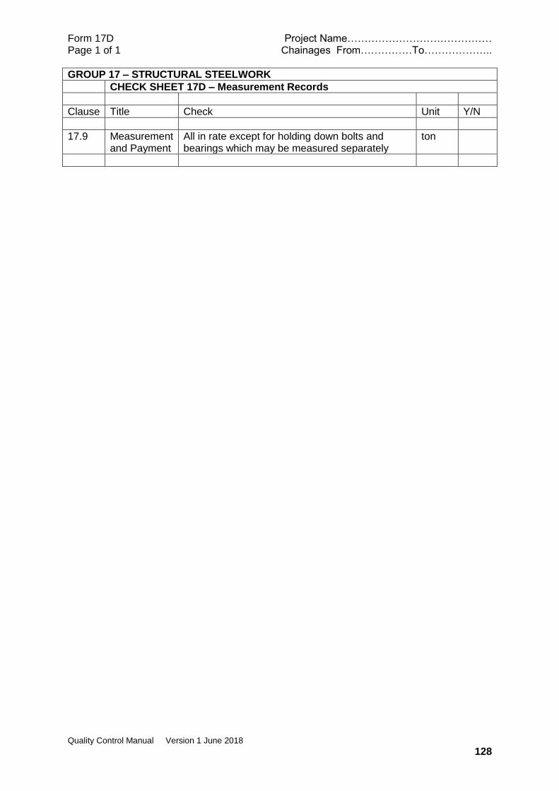
Form 17D Project Name…………………………………… Page 1 of 1 Chainages From……………To………………..
Quality Control Manual Version 1 June 2018
128
GROUP 17 – STRUCTURAL STEELWORK
CHECK SHEET 17D – Measurement Records
Clause Title Check Unit Y/N
17.9 Measurement and Payment
All in rate except for holding down bolts and bearings which may be measured separately
ton
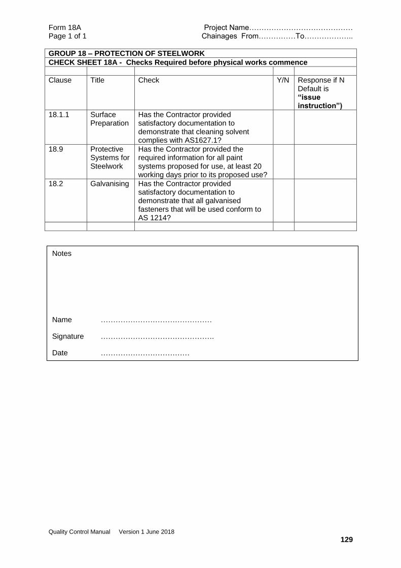
Form 18A Project Name…………………………………… Page 1 of 1 Chainages From……………To………………..
Quality Control Manual Version 1 June 2018
129
GROUP 18 – PROTECTION OF STEELWORK
CHECK SHEET 18A - Checks Required before physical works commence
Clause Title Check Y/N Response if N Default is “issue instruction”)
18.1.1 Surface Preparation
Has the Contractor provided satisfactory documentation to demonstrate that cleaning solvent complies with AS1627.1?
18.9 Protective Systems for Steelwork
Has the Contractor provided the required information for all paint systems proposed for use, at least 20 working days prior to its proposed use?
18.2 Galvanising Has the Contractor provided satisfactory documentation to demonstrate that all galvanised fasteners that will be used conform to AS 1214?
Notes
Name ………………………………………
Signature ……………………………………….
Date ………………………………
Form 18B Project Name…………………………………… Page 1 of 1 Chainages From……………To………………..
Quality Control Manual Version 1 June 2018
130
GROUP 18 – PROTECTION OF STEELWORK
CHECK SHEET 18B - Checks Require During or After Physical Works
Clause Title Check Y/N Response if N (default is “issue instruction”)
18.1 Shop Painting
18.1.1 Surface Preparation
Following the trial erection (Group 17.4), has the surface of all steelwork been adequately cleaned with approved solvent and prepared to Class 3 of AS 1672.4?
18.1.2 Priming Have all surfaces (except those specified as not to be primed) been given an approved Prime Coat? Note: Surfaces that are not to be primed are described in clause 18.1.3)
18.2 Galvanising Has the Contractor carried out any tests that are required to be carried out under AS 4680?
18.3 Field Painting
18.3.2 Painting Is the paint system approved? Note: It should be the one that was submitted for prior approval under clause 18.9?
Is the paint being applied in accordance with the Manufacturer’s instructions?
18.4 Transport and Storage
Is the paint being stored in accordance with the Manufacturer’s recommendations?
Is the paint less than 12 months old or within its recommended shelf life?
18.6 Repairs to Damaged Surfaces
Have damaged areas of protective coating been cleaned back to base metal and the edges of the damaged area bevelled?
Has the touch up paint been applied to overlap existing paint by 50mm?
18.8 Completed Joints
Have the unpainted but exposed parts of HSFG joints, including exposed parts of bolts, been painted as specified within 10 days of the joints being inspected and approved?
18.9.3 Seismic Restraints
Have seismic restraints that are not to be covered in concrete been protected as specified in this clause of the Specification?
Notes
Name ………………………………………
Signature …………………………… Date ………………
Form 18C Project Name…………………………………… Page 1 of 1 Chainages From……………To………………..
Quality Control Manual Version 1 June 2018
131
GROUP 18 – PROTECTION OF STEELWORK
CHECK SHEET 18C – Laboratory or Field Tests Required
clause Title Check Response
18.9.2 (e)
Application Coating thicknesses will need checking with paint gauges. Prime Coat to be 75 microns and top coats 100 microns
Notes
Name ………………………………………
Signature ……………………………………….
Date ………………………………
Form 18D Project Name…………………………………… Page 1 of 1 Chainages From……………To………………..
Quality Control Manual Version 1 June 2018
132
GROUP 18 – PROTECTION OF STEELWORK
CHECK SHEET 18D – Measurement Records
Clause Title Check Unit Y/N
17.9 Measurement and Payment
Included in the rate for steelwork.
Form 19A Project Name…………………………………… Page 1 of 1 Chainages From……………To………………..
Quality Control Manual Version 1 June 2018
133
GROUP 19 – MISCELLANEOUS BRIDGEWORK ITEMS
CHECK SHEET 19A - Checks Required before physical works commence
Clause Title Check Y/N Response if N Default is “issue instruction”)
19.2.2 Elastomeric Bearing
Has the Contractor submitted test certificates giving the physical properties and mechanical properties for each bearing proposed for use? Note: All bearings shall be indelibly marked with appropriate bearing type number and a unique number for correlation to test certificates.
Does the elastomer conform to AS 5100.4 with hardness IRHD 60 ±5?
19.3.4 Waterstop Has a brand of waterstop been proposed for approval?
19.3.5 Joint Filler Has the brand and type of the jointing material been submitted for approval?
Has the Contractor submitted test certificates detailing the compressive stress/strain relationship for the joint filler? Note: The stress to compress the joint filler to 50 percent of its original thickness shall be not less than 0.1 MPa and not greater than 0.3MPa.
19.3.6 Joint Sealant
Has the brand of the joint sealant been submitted for approval?
Notes
Name ………………………………………
Signature ……………………………………….
Date ………………………………
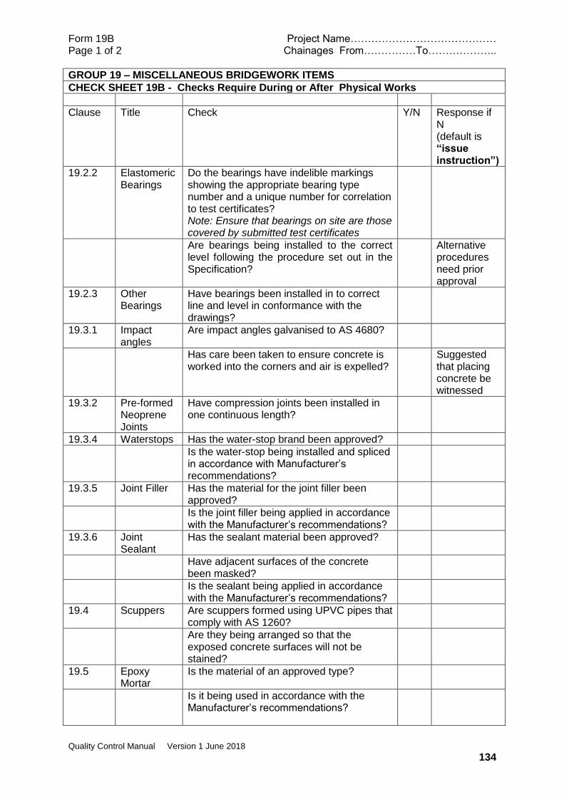
Form 19B Project Name…………………………………… Page 1 of 2 Chainages From……………To………………..
Quality Control Manual Version 1 June 2018
134
GROUP 19 – MISCELLANEOUS BRIDGEWORK ITEMS
CHECK SHEET 19B - Checks Require During or After Physical Works
Clause Title Check Y/N Response if N (default is “issue instruction”)
19.2.2 Elastomeric Bearings
Do the bearings have indelible markings showing the appropriate bearing type number and a unique number for correlation to test certificates? Note: Ensure that bearings on site are those covered by submitted test certificates
Are bearings being installed to the correct level following the procedure set out in the Specification?
Alternative procedures need prior approval
19.2.3 Other Bearings
Have bearings been installed in to correct line and level in conformance with the drawings?
19.3.1 Impact angles
Are impact angles galvanised to AS 4680?
Has care been taken to ensure concrete is worked into the corners and air is expelled?
Suggested that placing concrete be witnessed
19.3.2 Pre-formed Neoprene Joints
Have compression joints been installed in one continuous length?
19.3.4 Waterstops Has the water-stop brand been approved?
Is the water-stop being installed and spliced in accordance with Manufacturer’s recommendations?
19.3.5 Joint Filler Has the material for the joint filler been approved?
Is the joint filler being applied in accordance with the Manufacturer’s recommendations?
19.3.6 Joint Sealant
Has the sealant material been approved?
Have adjacent surfaces of the concrete been masked?
Is the sealant being applied in accordance with the Manufacturer’s recommendations?
19.4 Scuppers Are scuppers formed using UPVC pipes that comply with AS 1260?
Are they being arranged so that the exposed concrete surfaces will not be stained?
19.5 Epoxy Mortar
Is the material of an approved type?
Is it being used in accordance with the Manufacturer’s recommendations?
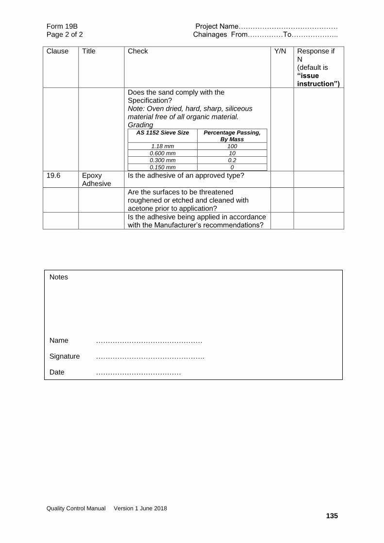
Form 19B Project Name…………………………………… Page 2 of 2 Chainages From……………To………………..
Quality Control Manual Version 1 June 2018
135
Clause Title Check Y/N Response if N (default is “issue instruction”)
Does the sand comply with the Specification? Note: Oven dried, hard, sharp, siliceous material free of all organic material. Grading
AS 1152 Sieve Size
Percentage Passing, By Mass
1.18 mm 100
0.600 mm 10
0.300 mm 0.2
0.150 mm 0
19.6 Epoxy Adhesive
Is the adhesive of an approved type?
Are the surfaces to be threatened roughened or etched and cleaned with acetone prior to application?
Is the adhesive being applied in accordance with the Manufacturer’s recommendations?
Notes
Name ………………………………………
Signature ……………………………………….
Date ………………………………

Form 19C Project Name…………………………………… Page 1 of 1 Chainages From……………To………………..
Quality Control Manual Version 1 June 2018
136
GROUP 19 – MISCELLANEOUS BRIDGEWORK ITEMS
CHECK SHEET 19C – Laboratory or Field Tests Required
clause Title Check Satisfactory Test results provided?
19.2.2 Elastomeric Bearings
Strength of mortar under bearings will need to be tested and confirmed AS 1012.8.1 and AS 1012.9
19.4 Epoxy Mortar
Sand may need testing for moisture content and grading.
Notes
Name ………………………………………
Signature ……………………………………….
Date ………………………………

Form 19D Project Name…………………………………… Page 1 of 1 Chainages From……………To………………..
Quality Control Manual Version 1 June 2018
137
GROUP 19 – MISCELLANEOUS BRIDGEWORK ITEMS
CHECK SHEET19 D – Measurement Records
Clause Title Check Unit Y/N
19.7 Measurement and Payment
Payment by number of each item
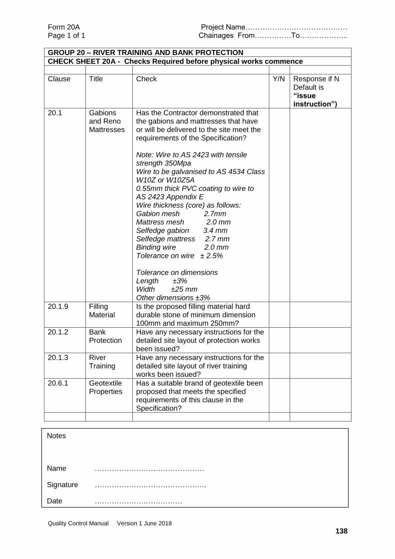
Form 20A Project Name…………………………………… Page 1 of 1 Chainages From……………To………………..
Quality Control Manual Version 1 June 2018
138
GROUP 20 – RIVER TRAINING AND BANK PROTECTION
CHECK SHEET 20A - Checks Required before physical works commence
Clause Title Check Y/N Response if N Default is “issue instruction”)
20.1 Gabions and Reno Mattresses
Has the Contractor demonstrated that the gabions and mattresses that have or will be delivered to the site meet the requirements of the Specification? Note: Wire to AS 2423 with tensile strength 350Mpa Wire to be galvanised to AS 4534 Class W10Z or W10Z5A 0.55mm thick PVC coating to wire to AS 2423 Appendix E Wire thickness (core) as follows: Gabion mesh 2.7mm Mattress mesh 2.0 mm Selfedge gabion 3.4 mm Selfedge mattress 2.7 mm Binding wire 2.0 mm Tolerance on wire ± 2.5% Tolerance on dimensions Length ±3% Width ±25 mm Other dimensions ±3%
20.1.9 Filling Material
Is the proposed filling material hard durable stone of minimum dimension 100mm and maximum 250mm?
20.1.2 Bank Protection
Have any necessary instructions for the detailed site layout of protection works been issued?
20.1.3 River Training
Have any necessary instructions for the detailed site layout of river training works been issued?
20.6.1 Geotextile Properties
Has a suitable brand of geotextile been proposed that meets the specified requirements of this clause in the Specification?
Notes
Name ………………………………………
Signature ……………………………………….
Date ………………………………
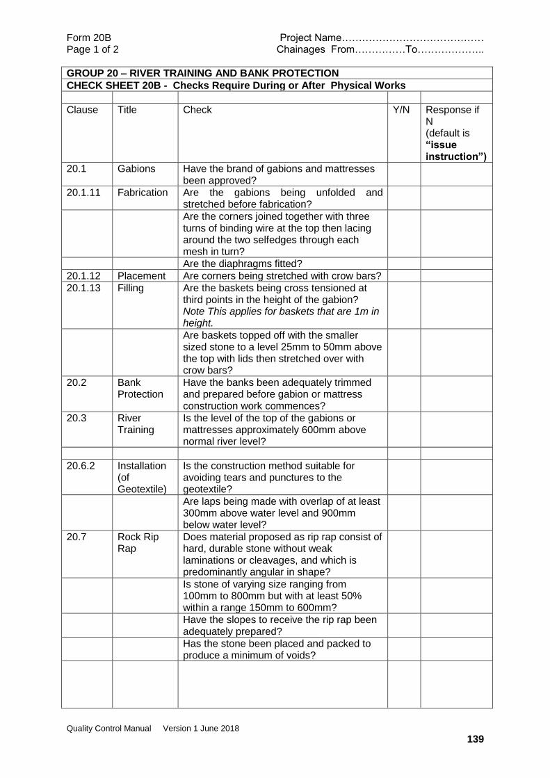
Form 20B Project Name…………………………………… Page 1 of 2 Chainages From……………To………………..
Quality Control Manual Version 1 June 2018
139
GROUP 20 – RIVER TRAINING AND BANK PROTECTION
CHECK SHEET 20B - Checks Require During or After Physical Works
Clause Title Check Y/N Response if N (default is “issue instruction”)
20.1 Gabions Have the brand of gabions and mattresses been approved?
20.1.11 Fabrication Are the gabions being unfolded and stretched before fabrication?
Are the corners joined together with three turns of binding wire at the top then lacing around the two selfedges through each mesh in turn?
Are the diaphragms fitted?
20.1.12 Placement Are corners being stretched with crow bars?
20.1.13 Filling Are the baskets being cross tensioned at third points in the height of the gabion? Note This applies for baskets that are 1m in height.
Are baskets topped off with the smaller sized stone to a level 25mm to 50mm above the top with lids then stretched over with crow bars?
20.2 Bank Protection
Have the banks been adequately trimmed and prepared before gabion or mattress construction work commences?
20.3 River Training
Is the level of the top of the gabions or mattresses approximately 600mm above normal river level?
20.6.2 Installation (of Geotextile)
Is the construction method suitable for avoiding tears and punctures to the geotextile?
Are laps being made with overlap of at least 300mm above water level and 900mm below water level?
20.7 Rock Rip Rap
Does material proposed as rip rap consist of hard, durable stone without weak laminations or cleavages, and which is predominantly angular in shape?
Is stone of varying size ranging from 100mm to 800mm but with at least 50% within a range 150mm to 600mm?
Have the slopes to receive the rip rap been adequately prepared?
Has the stone been placed and packed to produce a minimum of voids?

Form 20B Project Name…………………………………… Page 2 of 2 Chainages From……………To………………..
Quality Control Manual Version 1 June 2018
140
Clause Title Check Y/N Response if N (default is “issue instruction”)
20.8 Concrete Armouring
If concrete armouring is shown on the drawings has it been manufactured and placed as required?
Notes
Name ………………………………………
Signature ……………………………………….
Date ………………………………

Form 20C Project Name…………………………………… Page 1 of 1 Chainages From……………To………………..
Quality Control Manual Version 1 June 2018
141
GROUP 20 – RIVER TRAINING AND BANK PROTECTION
CHECK SHEET 20C – Laboratory or Field Tests Required
clause Title Check
NOT RELEVANT
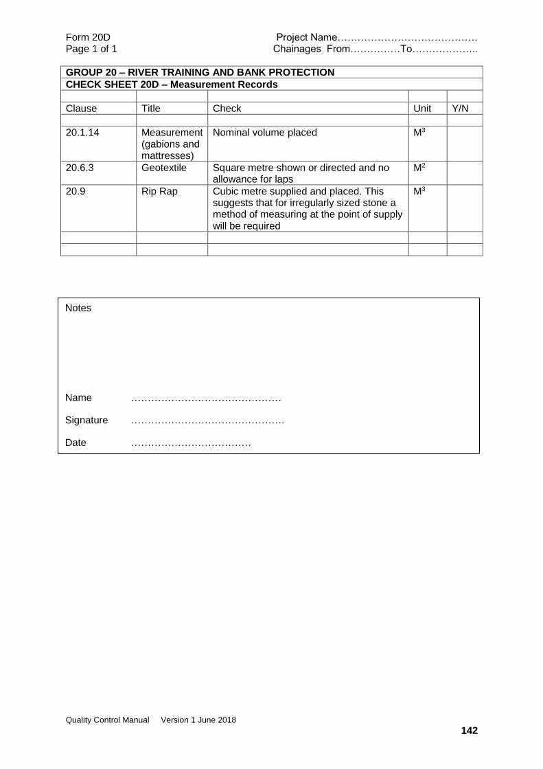
Form 20D Project Name…………………………………… Page 1 of 1 Chainages From……………To………………..
Quality Control Manual Version 1 June 2018
142
GROUP 20 – RIVER TRAINING AND BANK PROTECTION
CHECK SHEET 20D – Measurement Records
Clause Title Check Unit Y/N
20.1.14 Measurement (gabions and mattresses)
Nominal volume placed M3
20.6.3 Geotextile Square metre shown or directed and no allowance for laps
M2
20.9 Rip Rap Cubic metre supplied and placed. This suggests that for irregularly sized stone a method of measuring at the point of supply will be required
M3
Notes
Name ………………………………………
Signature ……………………………………….
Date ………………………………
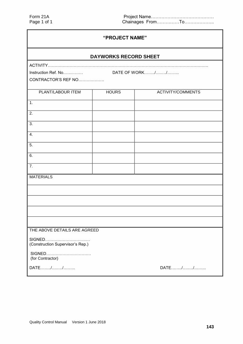
Form 21A Project Name…………………………………… Page 1 of 1 Chainages From……………To………………..
Quality Control Manual Version 1 June 2018
143
“PROJECT NAME”
DAYWORKS RECORD SHEET
ACTIVITY……………………………………………………………………………………………………….
Instruction Ref. No.…..……… DATE OF WORK……../….…./……...
CONTRACTOR’S REF NO……………….
PLANT/LABOUR ITEM
HOURS ACTIVITY/COMMENTS
1.
2.
3.
4.
5.
6.
7.
MATERIALS
THE ABOVE DETAILS ARE AGREED SIGNED…………………………… (Construction Supervisor’s Rep.) SIGNED…………………………… (for Contractor) DATE……../….…./……... DATE……../….…./……...

Form ATC 1 Project Name…………………………………… Page 1 of 1 Chainages From……………To………………..
Quality Control Manual Version 1 June 2018
APPENDIX A Forms for Contractor Notifications
Forms for Approval to Commence
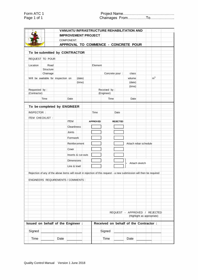
Form ATC 1 Project Name…………………………………… Page 1 of 1 Chainages From……………To………………..
Quality Control Manual Version 1 June 2018
VANUATU INFRASTRUCTURE REHABILITATION AND
IMPROVEMENT PROJECT
COMPONENT:
APPROVAL TO COMMENCE - CONCRETE POUR
To be submitted by CONTRACTOR
REQUEST TO POUR
Location Road Element
Structure
Chainage Concrete pour : class
Will be available for inspection on (date) volume m3
(time) (date)
(time)
Requested by : Received by :
(Contractor) (Engineer)
Time Date Time Date
To be completed by ENGINEER
INSPECTOR : Time Date
ITEM CHECKLIST :
ITEM APPROVED REJECTED
Cleanliness
Joints
Formwork
Reinforcement Attach rebar schedule
Cover
Inserts & cut-outs
Dimensions
Line & level
Rejection of any of the above items will result in rejection of this request - a new submission will then be required
ENGINEERS REQUIREMENTS / COMMENTS :
REQUEST - APPROVED / REJECTED
(Highlight as appropriate)
Issued on behalf of the Engineer : Received on behalf of the Contractor :
Signed Signed
Time Date Time Date
Attach sketch
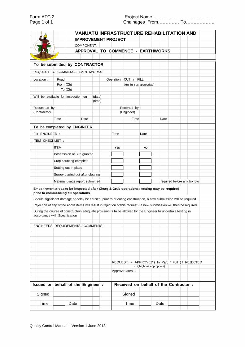
Form ATC 2 Project Name…………………………………… Page 1 of 1 Chainages From……………To………………..
Quality Control Manual Version 1 June 2018
VANUATU INFRASTRUCTURE REHABILITATION AND
IMPROVEMENT PROJECT
COMPONENT:
APPROVAL TO COMMENCE - EARTHWORKS
To be submitted by CONTRACTOR
REQUEST TO COMMENCE EARTHWORKS
Location : Road Operation : CUT / FILL
From (Ch) (Highlight as appropriate)
To (Ch)
Will be available for inspection on (date)
(time)
Requested by : Received by :
(Contractor) (Engineer)
Time Date Time Date
To be completed by ENGINEER
For ENGINEER : Time Date
ITEM CHECKLIST :
ITEM YES NO
Possession of Site granted
Crop counting complete
Setting out in place
Survey carried out after clearing
Material usage report submitted required before any borrow
Should significant damage or delay be caused, prior to or during construction, a new submission will be required
Rejection of any of the above items will result in rejection of this request - a new submission will then be required
During the course of construction adequate provision is to be allowed for the Engineer to undertake testing in
accordance with Specification
ENGINEERS REQUIREMENTS / COMMENTS :
REQUEST - APPROVED ( In Part / Full ) / REJECTED (Highlight as appropriate)
Approved area :
Issued on behalf of the Engineer : Received on behalf of the Contractor :
Signed Signed
Time Date Time
Embankment areas to be inspected after Cleag & Grub operations : testing may be required
prior to commencing fill operations
Date
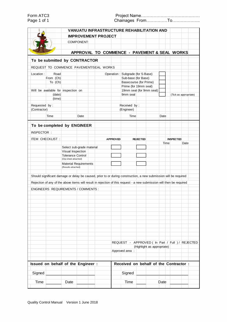
Form ATC3 Project Name…………………………………… Page 1 of 1 Chainages From……………To………………..
Quality Control Manual Version 1 June 2018
VANUATU INFRASTRUCTURE REHABILITATION AND
IMPROVEMENT PROJECT
COMPONENT:
APPROVAL TO COMMENCE - PAVEMENT & SEAL WORKS
To be submitted by CONTRACTOR
REQUEST TO COMMENCE PAVEMENT/SEAL WORKS
Location : Road Operation : Subgrade (for S-Base)
From (Ch) Sub-base (for Base)
To (Ch) Basecourse (for Prime)
Prime (for 19mm seal)
Will be available for inspection on 19mm seal (for 9mm seal)
(date) 9mm seal (Tick as appropriate)
(time)
Requested by : Received by :
(Contractor) (Engineer)
Time Date Time Date
To be completed by ENGINEER
INSPECTOR :
ITEM CHECKLIST : APPROVED REJECTED INSPECTED
Time Date
Select sub-grade material
Visual Inspection
Tolerance Control(Dip sheet attached)
Material Requirements(Results attached)
Should significant damage or delay be caused, prior to or during construction, a new submission will be required
Rejection of any of the above items will result in rejection of this request - a new submission will then be required
ENGINEERS REQUIREMENTS / COMMENTS :
REQUEST - APPROVED ( In Part / Full ) / REJECTED
(Highlight as appropriate)
Approved area :
Issued on behalf of the Engineer : Received on behalf of the Contractor :
Signed Signed
Time Date Time Date

Quality Control Manual Version 1 June 2018
APPENDIX B Site Record Forms
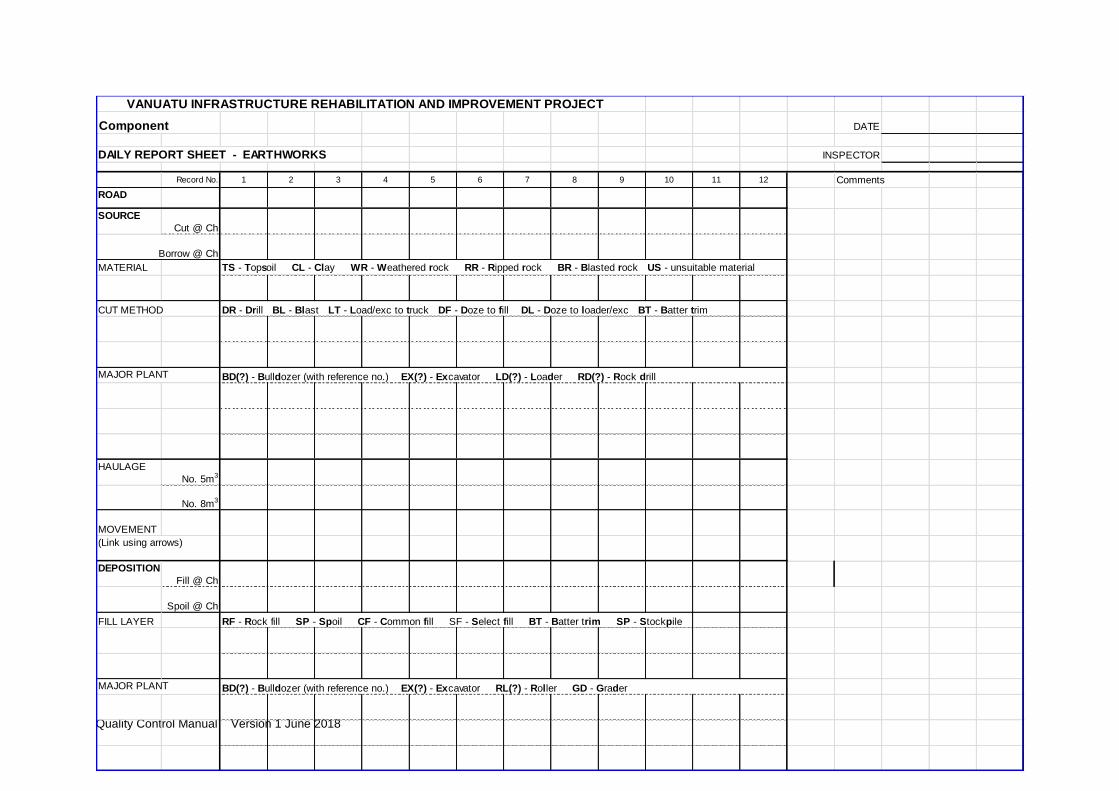
Quality Control Manual Version 1 June 2018
VANUATU INFRASTRUCTURE REHABILITATION AND IMPROVEMENT PROJECT
Component DATE
DAILY REPORT SHEET - EARTHWORKS INSPECTOR
Record No. 1 2 3 4 5 6 7 8 9 10 11 12 Comments
ROAD
SOURCE
Cut @ Ch
Borrow @ Ch
MATERIAL
CUT METHOD DR - Drill BL - Blast LT - Load/exc to truck DF - Doze to fill DL - Doze to loader/exc BT - Batter trim
MAJOR PLANT
HAULAGE
No. 5m3
No. 8m3
MOVEMENT
(Link using arrows)
DEPOSITION
Fill @ Ch
Spoil @ Ch
FILL LAYER RF - Rock fill SP - Spoil CF - Common fill SF - Select fill BT - Batter trim SP - Stockpile
MAJOR PLANT
TS - Topsoil CL - Clay WR - Weathered rock RR - Ripped rock BR - Blasted rock US - unsuitable material
BD(?) - Bulldozer (with reference no.) EX(?) - Excavator LD(?) - Loader RD(?) - Rock drill
BD(?) - Bulldozer (with reference no.) EX(?) - Excavator RL(?) - Roller GD - Grader

Quality Control Manual Version 1 June 2018
VANUATU INFRASTRUCTURE REHABILITATION AND IMPROVEMENT PROJECT
COMPONENT: DATE
DAILY REPORT SHEET - DRAINAGE (Culvert Installation) INSPECTOR
Record No. 1 2 3 4 5 6 Abbreviations
LOCATIONRoad
Chainage
Portion
DETAILSPurpose
Type
No. Barrels
Size
Material
WORK ITEM(s) Comments
MAJOR PLANT
LABOUR
Foreman/LH
Carpenter
Steel fixer
Labourer
Roads (allocate abbreviation)
Indicate as appropriate
HW(LorR) - Half w idth FW - Full w idth
CC - Cross culvert AC - Access
culvert SD - Storm drain DT -
Duct
CR(1/2…) - Crane BD(1/2…) - Bulldozer
EX(1/2…) - Excavator CT(No off) - Concrete
SW - Site Works EX(S/H) - Soft/Hard Excavation
PL - Pipe Laying RB(B/W/S/H) - Fix Rebar
(Base/Walls/Soffit/Headwall) FW(B/W/S/H) - Fix
Formwork CP(B/W/S/H) - Concrete Pour FP - Fix
panels BF - Backfill CH(I/O) - Chute(Inlet/Outlet)
P - Pipe B - Box A - Arch
Indicate as appropriate
Indicate as appropriate - size in mm's
PC - Precast concrete IC - Insitu
concrete CM(SorA) - Corrugated
metal (Steel or Aluminium) PVC
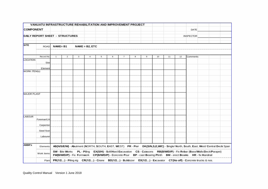
Quality Control Manual Version 1 June 2018
VANUATU INFRASTRUCTURE REHABILITATION AND IMPROVEMENT PROJECT
COMPONENT DATE
DAILY REPORT SHEET - STRUCTURES INSPECTOR
ROAD
Record No. 1 2 3 4 5 6 7 8 9 10 11 12 Comments
LOCATION
Site
Element
WORK ITEM(s)
MAJOR PLANT
LABOUR
Foreman/LH
Carpenter
Steel fixer
Labourer
Elements
Work items
Plant PR(1/2…) - Piling rig CR(1/2…) - Crane BD(1/2…) - Bulldozer EX(1/2…) - Excavator CT(No off) - Concrete trucks & nos.
SITENAME= B1 NAME = B2, ETC
ABBR'sAB(N/S/E/W) - Abutment (NORTH, SOUTH, EAST, WEST) PR - Pier DK(S/N,S,E,W/C) - Single/ North, South, East, West/ Central Deck Span
SW - Site Works PL - Piling EX(S/H) - Soft/Hard Excavation CS - Caissons RB(B/W/D/P) - Fix Rebar (Base/Walls/Deck/Parapet)
FW(B/W/D/P) - Fix Formwork CP(B/W/D/P) - Concrete Pour BP - cast Bearing Plinth BM - erect Beams HR - fix Handrail
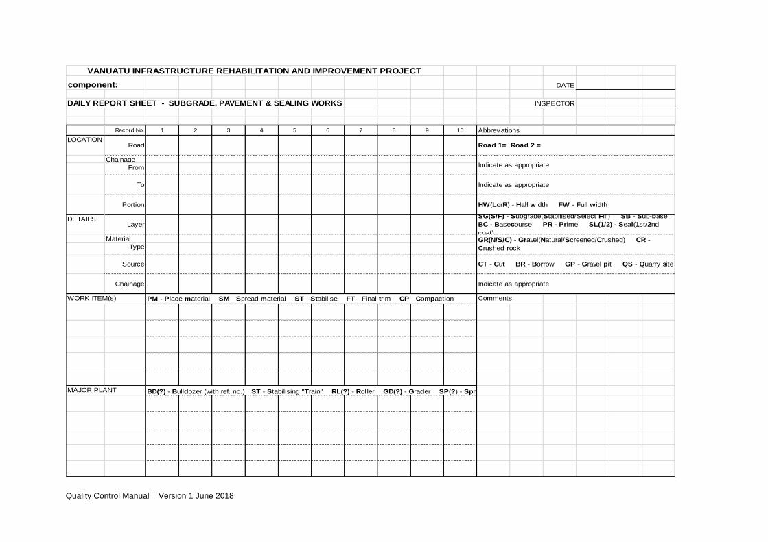
Quality Control Manual Version 1 June 2018
VANUATU INFRASTRUCTURE REHABILITATION AND IMPROVEMENT PROJECT
component: DATE
DAILY REPORT SHEET - SUBGRADE, PAVEMENT & SEALING WORKS INSPECTOR
Record No. 1 2 3 4 5 6 7 8 9 10 Abbreviations
LOCATIONRoad
Chainage
From
To
Portion
DETAILSLayer
Material
Type
Source
Chainage
WORK ITEM(s) Comments
MAJOR PLANT
Road 1= Road 2 =
SG(S/F) - Subgrade(Stabilised/Select Fill) SB - Sub-base
BC - Basecourse PR - Prime SL(1/2) - Seal(1st/2nd
coat)
BD(?) - Bulldozer (with ref. no.) ST - Stabilising "Train" RL(?) - Roller GD(?) - Grader SP(?) - Sprayer
PM - Place material SM - Spread material ST - Stabilise FT - Final trim CP - Compaction
Indicate as appropriate
GR(N/S/C) - Gravel(Natural/Screened/Crushed) CR -
Crushed rock
HW(LorR) - Half w idth FW - Full w idth
Indicate as appropriate
Indicate as appropriate
CT - Cut BR - Borrow GP - Gravel pit QS - Quarry site

Quality Control Manual Version 1 June 2018
APPENDIX C - Guidance for Additional Sheets
Additional sheets will be required for projects that contain a Supplementary Specification.
These should be prepared by the Project Manager at the commencement of the project as
soon as the Supplementary Specification has been finalised

Quality Control Manual Version 1 June 2018
[insert document reference eg Supplementary Specification Group 4]
CHECK SHEET [ insert sheet no and A,B,C or D] A = Requirements Before Physical Works Commence B = Requirements During or After Physical Works C = Laboratory or Field Tests Required D = Measurement Records
Clause Title Check Y/N Response if N (default is “issue instruction”)
[insert clasue reference
[insert clause title]
[Summarise the requirement to ve verified in the form of a question to which the answer is either ‘Ye” or “No”]
[insert any further guidance that inspectors may need]