Quality Audit report of Carriage Workshop Kharagpur, SE...
24
Quality Audit report of Carriage Workshop Kharagpur, SE Rly Report no. 77/2012 MAY 2012 ( Audit is done by CWM, ECoR ) Co-ordinated by Quality Assurance ( Mechanical ) Directorate Research Designs & Standards Organisation Manak Nagar, Lucknow - 226011
Transcript of Quality Audit report of Carriage Workshop Kharagpur, SE...

Quality Audit report
of
Carriage Workshop
Kharagpur, SE Rly
Report no. 77/2012
MAY 2012
( Audit is done by CWM, ECoR )
Co-ordinated by
Quality Assurance ( Mechanical ) Directorate
Research Designs & Standards Organisation Manak Nagar, Lucknow - 226011

Page 1 of 23 Carriage Workshop – KGP, SE Rly May 2012
Quality audit Report of Kharagpur Carriage Workshop, South Eastern Railway
1.0 Introduction
Railway Board vide letter no. 2012/M(W)814/5 dated 20.3.12 has instructed RDSO/ Zonal Railways to conduct quality audit of coaching depots and workshops. CWM/ECoR was assigned to carry out audit of Kharagpur Workshop, South Eastern Railway.
1.1 Audit Team – Shri Arjun Mundiya, CWM,MCSW, Shri P P Beura, JE, Bogie Shop Shri M K Das, JE, Wheel Shop.
1.2 Date of Audit – 02.05.2012.
1.3 Escorting officers from workshop – S/Shri Sita Ram Sinku, CWM, Shri Amit Sinha, DyCME(carriage), Shri P. Prabhakar, DyCME(production).
1.4 Scope of audit - Quality audit of Roller bearing, Wheels and axles, Bogie overhauling, Maintenance of brake block hanger, Interior fittings (furnishings) and Air brake system, availability of infrastructure and M& P facilities etc.
During the audit, the strengths and areas needing further attention were discussed. 2.0 Brief of visit
Kharagpur Workshop is one of the largest workshops of Indian Railways carrying out POH of coaches, EMUs, Electric locomotives and Diesel locomotives within one boundary wall. The audit was carried out in the areas of coach POH activities.
The targeted out turn is 139 coaches per month inclusive of 25 AC coaches. In addition, 7 motor coaches and 17.5 trailer coaches of EMU rakes are turned out every month. The bogie overhauling requirement of 226 nos. for coaching depots is also being met by the workshop.
3.0 Strengths
3.1 For cutting of stainless steel trough floor longitudinally, plasma cutting machine with
guided torch is being used. Similarly, the coach panel cutting on corrosion repair coaches is also done using guided torch plasma cutting machine.
3.2 Blue colour Epoxy flooring being done in toilets of GSCN coaches is aesthetically superior to PVC flooring and also ensures proper slope to avoid water stagnation.
3.3 In order to prevent unevenness getting developed on toilet floors fitted with stainless inlays, the fabricated channel frame is laid below the inlays.
3.4 The paint shop roof is provided with wind turbines to effectively extract paint fumes. 3.5 In seat/berth repair/manufacturing, felt strips are put between the rexin and metal
edges, so that tearing of the former is avoided.
3.6 BSS hangers are being subjected to elongation tests.

Page 2 of 23 Carriage Workshop – KGP, SE Rly May 2012
3.7 The machine for crack detection of coil springs has a mechanized loading and unloading system which is a highly productive.
3.8 The workshop has huge covered area with crainage facility.
4.0 Weaknesses
4.1 Wheel turning is the weak area as all the three wheel lathes are old.
4.2 EOT cranes particularly the gantry rails are worn out which leads to frequent replacement of crane wheels.
4.3 Bearing cleaning plant and Axle Box cleaning plant are required for improving maintenance.
4.4 Though roller bearing shop is well laid out, general maintenance leaves lot of room for improvement. The shop is not dust free.
4.5 The dismounting of roller bearings from IOH due bogie wheel sets is carried out on condition basis. Otherwise only re-greasing is being done. This practice needs review in view of 8 (eight) hot axle cases leading to coach detachments during 2011-12.
4.6 Cleaning of bogies is inadequate. Shot blasting is being done only for 2 bogies per day against average arising of 12 bogies per day.
4.7 Magnaflux testing of block hangers is not being done.
4.8 The system of fitment of brake lever bushes is very crude. These are fitted using hammer.
4.9 Bogie load testing machine is not available as such it is not being done.
4.10 Pipes & pipes brackets and other air brake equipments are being tested with 7 kg/cm2 air pressure instead of 10 kg/cm2

Page 3 of 23 Carriage Workshop – KGP, SE Rly May 2012
CHECK SHEET FOR QUALITY AUDIT OF WHEEL SETS AND ROLLER BEARINGS FOR BG COACHES OF ICF DESIGN
(BASED ON CAMTECH MAINTENANCE MANUAL FOR BG COACHES OF ICF DESIGN AND TECHNICAL PAMPHLET C-7817)
During the audit at Kharagpur Workshop Wheel shop under–mentioned activities as recommended CAMTECH manual and C-87817 technical pamphlet have been checked for compliance. Wherever the activities are not perfo4rmed correctly methods adopted or the natures of non-compliance have been recorded:
SN REQUIREMENTS CLAUSE OBSERVATIONS 1. Check that wheel gauge (1600+2/-1) is being
measured at 3 location 60º apart. 1001 c (ia) Being followed.
2. Check that wheel dia is being measured with the help of trammel gauge with least count of 0.5mm or wheel dia measuring gauge of least count of 0.1mm. Check that wheel flanges are being checked with the help of wheel profile gauge and thickness and height of flanges is being measured. The difference in tread dia of the two wheels on the same axle permitted is 0.5mm max and this is being measured. Check that wheels turned out from wheel shop are according to shop issue sizes.
1001 c (i) (b & d)
Being followed.
ICF/BEML solid New-915 Shop issue-836 3. Check that each axles are being thoroughly cleaned for
inspection & inspected for pitting, ovality, taper, ridges & ultrasonically as per RDSO procedure.
Taper must not exceed – 0.015/0.01mm
Out of roundness must not exceed-0.015/0.02mm
1001 (i) (e) Being followed.
4. Check that wheels are being categorized into following categories after pre-inspection. (i) Normal repair wheels. (ii) Wheels requiring replacement of Axle. (iii) Wheels requiring replacement of Wheel discs
1002 Being followed.
5. The wheel should be inspected for rejectable defects in accordance with CMI/K003.
1001 c (i) (c) Being done.
6. Check that wheels are being turned to WWP & machining standard is N11 to IS:3073.
C-7817 Being followed.
7. Check that when wheels sent for turning with roller bearings, a protective cover is provided.
C-7817 Being done.
8. Check that new axles are being machined as per the correct drawing dimensions.
1003 b Being followed.
9. Check that dimensions of finished journals is being measured with micrometer at 3 points along length of the journal both on horizontal & vertical axis.
C-7817 Being followed.
10. Check that axles are being given ultrasonic flaw detection test.
1001 c (e) Being done.
11. Check that the bore & the wheel seats are having specified surface finish & correct interference fit and pressing in pressure interference allowed – 0.20 to 0.24mm Surface finish – 1.6 microns Pressing in pressure – 400 to 600 kg./mm dia of wheel seat.
1003 Being followed.
12. Check that after dropping of axle boxes and roller bearing dismounted, the journal dia is being checked and wheels are being ultrasonic tested for flaw detection.
1003 Being followed.
13. Check that cleaned wheel seat and bore on wheel is being lubricated with a mixture of basic carbonate white lead and boiled linseed oil in the proportion of 1.2 kg of white lead to 1 lt. of boiled linseed oil.
1003 Being followed.
14. Check that wheel press is equipped with a dial pressure gauge and pressure recording gauge with
1003 Being done
Page 4 of 23 Carriage Workshop – KGP, SE Rly May 2012
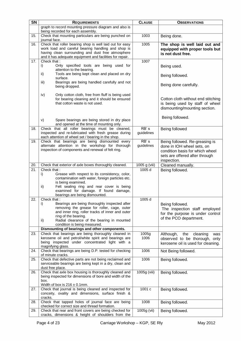
SN REQUIREMENTS CLAUSE OBSERVATIONS graph to record mounting pressure diagram and also is being recorded for each assembly.
15. Check that mounting particulars are being punched on journal face.
1003 Being done.
16. Check that roller bearing shop is well laid out for easy work load and careful bearing handling and shop is having clean surrounding and dust free atmosphere and it has adequate equipment and facilities for repair.
1005 The shop is well laid out and equipped with proper tools but is not dust free.
17. Check that : i) Only specified tools are being used for
attention to the bearing. ii) Tools are being kept clean and placed on dry
surface. iii) Bearings are being handled carefully and not
being dropped. iv) Only cotton cloth, free from fluff is being used
for bearing cleaning and it should be ensured that cotton waste is not used.
v) Spare bearings are being stored in dry place
and opened at the time of mounting only.
1007 Being used. Being followed. Being done carefully. Cotton cloth without end stitching is being used by staff of wheel dismounting/mounting section. Being followed.
18. Check that all roller bearings must be cleaned, inspected and re-lubricated with fresh grease during each attention of wheel set / bearing in the shop.
RB’ s guidelines
Being followed
19. Check that bearings are being dismounted every alternate attention in the workshop for thorough inspection of components and renewal of felt ring.
RB’ s guidelines
Being followed. Re-greasing is done in IOH wheel sets, on condition basis for which wheel sets are offered after through inspection.
20. Check that exterior of axle boxes thoroughly cleaned. 1005 g (viii) Cleaned manually. 21. Check that :
i) Grease with respect to its consistency, color, contamination with water, foreign particles etc. is being examined.
ii) Felt sealing ring and rear cover is being examined for damage. If found damage, bearings are being dismounted.
1005 d Being followed.
22. Check that : i) Bearings are being thoroughly inspected after
removing the grease for roller, cage, outer and inner ring, roller tracks of inner and outer ring of the bearing.
ii) Radial clearance of the bearing in mounted condition is being measured.
1005 d Being followed. The inspection staff employed for the purpose is under control of the PCO department.
Dismounting of bearings and other components. 23. Check that bearings are being thoroughly cleaned in
kerosene oil and petrol/white spirit and bearings are being inspected under concentrated light with a magnifying glass.
1005g 1006
Although, the cleaning was observed to be thorough, only kerosene oil is used for cleaning.
24. Check that bearings are being D.P. tested for checking of minute cracks.
1006 Not Being followed.
25. Check that defective parts are not being reclaimed and serviceable bearings are being kept in a dry, clean and dust free place.
1006 Being followed.
26. Check that axle box housing is thoroughly cleaned and being inspected for dimensions of bore and width of the box. Width of box is 216 ± 0.1mm.
1005g (viii) Being followed.
27. Check that journal is being cleaned and inspected for conceity, ovality and dimensions, surface finish & cracks.
1001 c Being followed.
28. Check that tapped holes of journal face are being checked for correct size and thread formation.
1008 Being followed.
29. Check that rear and front covers are being checked for cracks, dimensions & height of shoulders from the
1005g (vii) Being followed.

Page 5 of 23 Carriage Workshop – KGP, SE Rly May 2012
SN REQUIREMENTS CLAUSE OBSERVATIONS face.
30. Check that locking bolts are of correct size and of specified quality & are being inspected for any damage.
1005g (iii) Being followed.
31. Check that retaining ring and ring are being inspected for flatness and dimensions.
1005g (iv) Being followed.
32. Check that dismounted collars are not being reused. 1005g (v) Being followed. 33. Check that felt ring of dismounted box is not being
reused and new felt ring is being fitted after proper treatment.
1005g (vi) Being followed.
34. Check that bearings are being heated in oil bath / induction heater before fitment in the temperature range of 100
0 C to 120
0 C and ensure that temperature
of bearing does not exceed 1200 C.
1006 b Being followed.
35. Check that end locking bolts are being tightened with torque wrenches with specified torque value. 11 to 12 kgm for M16 bolts 15 to 16 kgm for M20 bolts.
1005 d Being followed.
36. Check that only specified quantity of grease is being used to pack the bearings. 2.0 kg for SKF make 1.75 kg for other makes.
1005 f Volumetric containers for grease of 2.0 Kg and 1.75 Kg (2 for each) are available.
37 Check that grease drums are being stored in vertical position in a covered space.
1005 f Checked, found OK.

Page 6 of 23 Carriage Workshop – KGP, SE Rly May 2012
LIST OF TOOLS & PLANT FOR WHEELS & AXLES
S.N M&P / Tools Remarks
1 EOT crane 5 tonne available
2 Wheel profiling lathe Available
3 Axle journal turning and burnishing lathe Available
4 Axle journal grinding machine for assembled wheel
set
Not available
5 Hydraulic wheel press with facility for mounting
pressure diagram
Available
6 Axle turning lathe Available
7 Vertical turning lathe Available
11 Axle centering machine Not Available
12 Axle end drilling machine Available
13 Axle grinder Not available
LIST OF TOOLS & PLANT FOR ROLLER BEARINGS
S.
N
M&P / Tools Remarks
1 Automatic roller bearing cleaning plant with 3-stage cleaning of pre-wash, wash and hot water rinsing.
Available.
2 Axle box cleaning plant with bosch tank and spray jet cleaning in closed chamber, having conveyor facility
Available without conveyor facility.
3 Axle box extractor Available
4 Hydraulic dismounting equipment for direct mounted spherical roller bearing.
Available
5 Induction heater with demagnetising device Available
6 Torque wrench and torque wrench tester. Available
7 Feeler gauge set. Available
8 Outside micrometer for journal and shoulder diameter measurement.
Available
9 Three legged inside micrometer with 0.05mm least count for inner race bore Measurement.
Available
10 Magnifying glass with light. Available
11 Volumetric containers for grease. Available
12 Thread ring gauges for end locking screw inspection. Available
13 Thread plug gauges for end locking holes. Available
14 Engraving/etching machine. Available

Page 7 of 23 Carriage Workshop – KGP, SE Rly May 2012
CHECK SHEET FOR QUALITY AUDIT OF
BOGIE OVERHAUL FOR BG COACHES OF ICF DESIGN (BASED ON CAMTECH MAINTENANCE MANUAL FOR BG COACHES
OF ICF DESIGN
While doing the audit, ensure that the below mentioned activities are carried out as specified in the Coaching Maintenance manual. Wherever the activities are not performed correctly indicate the method adopted or the nature of non-compliance. SN ACTIVITY CLAUSE OBSERVATIONS 1. Ensure that the bogies are washed with high pressure
hot water jet to remove all the dust/dirt etc. 316a Cleaning of bogies is inadequate.
High pressure cold water jet is available and Shot blasting of bogies being done through outsourcing, for which 02 bogies per day are transported to outside.
2. Ensure that all the components are dismantled as specified and sent to respective sections.
316b Being followed.
3. The bogie is checked for cracks. Also BSS bracket, axle guides, area surrounding the BSS brackets and axle guides and the welding joints of top and bottom Hangers of side frame are checked.
316c (i) Being followed. Cracks are checked with flame.
4. Ensure that down hand welding is ensured by using manipulator to repair the cracks.
Being followed.
5. The BSS brackets or axle guides if worn/damaged or cracked are replaced.
316c (ii) Being followed.
6. Ensure that Safety wire rope arrangement and safety straps should be used for brake beams as per revised RDSO instructions.
316c (iv) Being followed. Attended on condition basis.
7. Ensure that the squarencess and alignment of BSS brqckets and axle guides is checked using suitable gauges and relocated if necessary.
316c (v) 316c (vi)
Being followed.
8. The axle guides should be attended for crack/worn threads.
316c (vii) Attended for crack. Non-modified guides are changed with modified one.
9. Ensure that axle guides are welded with the help of welding fixtures.
316c (viii) Being followed.
10. The BSS bracket bushes and pins are replaced if damaged/worn.
316c (ix) Being followed.
11. Ensure that anchor link brackets are replaced when worn/damaged and attended for M12 threaded hole.
316c (x) Being followed.
12. Attention is paid to the brake hanger as specified. 316c (xi) 316c (xii)
Being followed.
13. The bolster is checked for twist/cracks and corrosion etc. and repair/replaced.
316d Being followed.
14. Ensure that the equilising stay brackets are repaired/replaced if necessary. Ensure that the various components i.e. the anchor link bracket, bushes in the stay rod bracket, centre pivot sleeve and bolster centre pivot sleeve is replaced/repaired if found worn/damaged/cracked/ corroded.
316f
316e
Being followed.
15. Ensure that centre pivot silent block and it’s sealing cap is replaced it found torn/damaged/ perished.
316d (v) 316d (viii)
Being followed.
16. Centre pivot pin is checked for chalk test and detection of cracks.
316d (ix) Being followed.
17. Ensure that force fit between salient blocks and sleeve and tolerances on pivot pin is maintained in every POH/IOH.
316d (x) Being followed.
18. Ensure that side bearers are attended to as specified. 316d (xi) Being followed. 19. The locations where the repairs have been carried out
or corroded are clean to bare metal and painted. 316d (xiii) Being followed.
20. The anchor links are replaced if worn/corroded or repaired if found cracked and tested by magna flux method.
316e (i) Being followed. DPT of anchor links is done.

Page 8 of 23 Carriage Workshop – KGP, SE Rly May 2012
SN ACTIVITY CLAUSE OBSERVATIONS 21. Ensure that the salient block is attended for rubber as
well as force fit. 316e (ii) Being followed.
22. Ensure that the equalising stay rod and pin are attended as specified.
316 f Being followed.
23. Clean the BSS hangers and check for cracks and wear. The hangers are replaced if wear exceeds 1mm.
316 h (i) Being followed.
24. Ensure that the magna flux crack detection equipment
is used for checking the cracks. 316 h (i) Being followed.
25. Ensure that the repair to BSS hangers is done as specified.
316 h (ii) Renewed on condition basis.
26. Hanger blocks are checked for cracks by magna flux test and worn hangers blocks are built up by using 2B electrodes and machined to size.
316 i Hanger block is checked visually. Magnaflux testing is not done.
27. Ensure that all the components i.e. upper and lower rubber washer, packing rings, guide rings, dust shield, guide bush dust shield spring and spring clip are replaced.
316j (ii) Being followed. Hytrel washers are replaced on condition basis. Other items are changed during POH. During IOH, dust shield and spring clip are replaced. Complaints are being lodged against premature changing of lower Hytrel washers.
28. The lower spring seat is checked and replaced/reclaimed if necessary.
317 Being followed.
29. The springs are cleaned thoroughly in Bosch tank. Being followed. 30. The springs are inspected by magna flux/chalk test to
detect cracks. Magnaflux testing is being done.
31. Each spring is subjected to incremental load as specified.
Being followed.
32. After load deflection, the springs are painted. Being followed. 33. The springs are grouped into three groups as per
deflection. Being followed.
34. Ensure that brake levers/bushes are replaced. 318 Bushes are fitted with hammer. 35. The components of brake gear such as worn brake
beams, brake head shoes, brake gear pins are replaced/repaired.
Being followed.
36. The brake gear pins should be used which are case hardened, crown finish and chromium plated.
318 Being followed
37. Ensure that maximum permissible clearance between brake gear pins and bush is 1.5mm.
Being followed. Visual checking is done.
38. All the brake gear components are given two coats of red oxide primer, 4 coats of bituminous solution and one coat of anti-corrosive black paint.
One coat of primer and one coat of anti corrosive black paint applied.
39. Ensure that a sub, store is available in the shop to ensure supply of proper components and sub assembly for bogie assembly.
319a Being ensured.
40. Ensure that during assembly, cotters are splitted min 45
0 and not slack in the pins modified levers hanger
pins are used to prevent the bush working of the lever hanger.
319b (ii) Being followed.
41. Ensure that while tightening guide cap guide bush sits tight against the rubber packing ring and holes, in the guide are in alignment with corresponding holes in the guide bush.
Cap type guides have been completely modified.
42. Ensure that the wheel sets are selected in such a way that the variation in the diameter of the wheels in the same bogie and in the same coach does not exceed the specified limits.
319d (i) Being followed.
43. The assembled bogie should be load tested on a bogie test stand where it is lowered up to its normal working load and height of the bolster top surface from rail level should be measured for comparison with pre-determined dimension corresponding to correct coach buffer height.
319d (v) Bogie load testing machine is not available.
44. Ensure that maximum modifications to different bogie components issued by RDSO are carried out during
Appendix D Being followed.

Page 9 of 23 Carriage Workshop – KGP, SE Rly May 2012
SN ACTIVITY CLAUSE OBSERVATIONS POH.
SHOCK ABSORBERS : 1. Ensure that shock absorber are given POH when the
capacity is beyond ± 20% of the specified value on after 4 lakhs kms or alternate POH which ever is earlier.
319f Being ensured.
2. The shock absorber is tested to measure its capacity in both tension and compression by developing the existing force at a velocity of 10cm per sec.
Being followed.
3. Ensure that the shock absorbers are properly painted covered and stamped.
Being done.

Page 10 of 23 Carriage Workshop – KGP, SE Rly May 2012
LIST OF TOOLS & PLANTS FOR BOGIES
LIFTING SHOP
Ball pin hammer Available
Chisel Available
Spanner Available
WASHING PLANT
Bosch tank Available.
Hot water jet system Available with cold water..
Waste water treatment plant Not available.
Bins and pallets Available
Jib crane Not Available
Fork lift Available
Platform truck Available
BOGIE SHOP
Ball pin hammer Available
Chisel Available
Standard spanner set Available
Welding transformer Available
Gas cutting plant Available
Bogie alignment gauges Available
Spring testing machine Available
Magna flux crack detector Available
Paint brushes Available
Floor scraper Not Available
Platform truck Available
Bogie test rig working stands available
Overhead crane Available
Bins and pallets Available
Fork lift Available
FITTING SHOP
Ball pein hammer Available
Chisel Available
Welding transformer Available
Gas cutting plant. Available
Hydraulic press Available
Measuring gauges Available
Centre lathe Available at M&S shop
Brake beam end turning m/c. Not available
Electrode heater Available
BSS hanger testing machine Not Available
Bins and pallets Available
Fork lift Available
Platform truck Available

Page 11 of 23 Carriage Workshop – KGP, SE Rly May 2012
CHECK SHEET FOR QUALITY AUDIT OF BRAKE BLOCK HANGER FOR BG COACHES OF ICF DESIGN
(BASED ON CAMTECH MAINTENANCE MANUAL)
While doing the audit, ensure that the below mentioned activities are carried out as specified in the Coaching Maintenance manual. Wherever the activities are not performed correctly indicate the method adopted or the nature of non-compliance.
SN Requirements Observations
1
Railway must conduct audit checks on the new supply of brake hanger received by them and should maintain records
The new supplies are RITES inspected and the material is stock item
2
Hanger should be removed from coaches during POH/IOH. They should be cleaned and checked visually for cracks, distortion or excessive corrosion. Hanger found serviceable should be
Checked for wear on the bore of the hole with the help of a plug gauge.
Magnaflux / chalk tested for any cracks before they are put into service.
Being followed.
Other observations:
1. TSO/LTO/Work Instructions on maintenance of brake block hanger: Work Instruction available.
2. Rejection of brake block hanger: 7.35% approx.(derived from last 06 months’ trends.) 3. Average POH/IOH attention: 170 coaches per month. 4. Procurement during last three years is as under:
Year Total procurement
2009-10 3600 nos.
2010-11 2549 nos
2011-12 3600 nos.
5. Procurement status of brake block hanger as per revised drawing: It is a stock item. 6. Details of brake block hangers checked and rejected are detailed as under:
Month BB hangers checked
Passed Rejected % rejection
Cause of rejection
Dimension Pitted M/flux
Oct, 11 2475 2320 155 6.26 90 32 33
Nov, 11 3187 3033 154 4.83 110 36 08
Dec, 11 3222 3004 218 6.76 120 50 48
Jan, 12 3185 2928 257 8.06 170 68 19
Feb, 12 3225 2959 266 8.24 185 51 30
Mar, 12 3075 2768 307 9.98 209 60 38
7. Last quality audit done (internal): - No internal audit has been done earlier. 8. Other observations:

Page 12 of 23 Carriage Workshop – KGP, SE Rly May 2012
CHECK SHEET FOR QUALITY AUDIT OF INTERIOR FITTINGS (FURNISHINGS) (BASED ON CHAPTER 11 OF CAMTECH MAINTENANCE MANUAL
FOR BG COACHES OF ICF DESIGN)
While doing the audit, activities are checked with regard to as specified in the maintenance manual. Wherever the activities are not performed correctly, the method adopted is indicated or the nature of non-compliance is recorded.
SN Requirements Clause Observations
1.0 Interior fittings such as panels, seats, berths, windows, lights, fans, sanitary fittings, etc. should be furnished as per Rly/RDSO standard for various types and classes of vehicle.
1101 Being followed.
2.0 Amenity Fittings – Various passenger amenities fittings should be provided as per table no.11.1 of Chapter 11 of CAMTECH manual
1102 Being followed.
3.0 Plastics, FRP and various other synthetic materials are now a days used which are light in weight and requires less maintenance and give better aesthetics. Status of implementation during POH
1103 Being followed.
3.1 Roof Paneling Sheet: 2 mm thick limpet asbestos sheet or 1.5 mm thick NFTC should be used.
1103a Being followed.
3.2 Side Wall Paneling: 3 mm thick thermosetting synthetic resin bonded decorative LP Sheets (C-9602) should be used.
1103b Being followed.
3.3 Use of other Plastic Materials :
SMC moulded window shutters, Wall protector and Axle box cover
Plastic Push Cock made of HDPE, PTMT and acetal material..
1103c Being followed.
4.0 Attention in Workshop :
Inspect interior fittings for corrosion and damage, Missing, defective fittings should be refitted/repaired.
All distorted/damaged panels should be replaced. No patch work allowed. While replacing the panels, care should be taken to match the colour and design.
After 5-7 years while attending corrosion on the roof sheets, deficient/damaged insulation should be replaced.
1103d Being followed.
5.0 Anti Pilferage Measures: To prevent theft, anti pilferage measures should be taken as advised by CME or RDSO.
1103e Being followed.
6.0 Window 1104
6.1 Window of non-AC coaches –
Check balancing mechanism of glass shutter from dripping.
Check spring loaded safety latch to prevent Louvre shutter from falling
1104a Being followed.
6.2 Window of AC Coaches : Sealed windows of both ICF or RCF design should meet the following requirement: 5.5 / 6 mm thick toughened safety glass (IS2553, Part-II) are used in window. A reflective sun control film of smoke grey colour is pasted on inside surface of outer glass.
1104b Being followed.

Page 13 of 23 Carriage Workshop – KGP, SE Rly May 2012
SN Requirements Clause Observations
6.3 Emergency openable window – It is provided as 4 nos. in Non AC coaches (3
rd window from both end).
2 nos. in AC coaches (3rd
window from both end)
1104c Being followed.
6.4 Lavatory Windows of Non AC coaches – FRP banjo type windows frosted glass are fitted in lab.
1104d Being followed.
6.5 Lavatory windows of AC coaches – Sealed type windows with frosted glass are fitted in lavatory of AC coaches.
1104e Being followed.
6.6 Maintenance of AC windows in workshops –
Replace broken, cracked, defected or scratched window.
Glass should be cleaned with lime and detergent before fitting.
The hinges of inner window frame should be checked well oiled before fitting.
The rubber beading between window and coach body should be replaced if found set, deteriorated or damaged to ensure air tightness.
The damaged FRP inner frames / holding frame should be replaced.
1104f Being followed.
6.7 Maintenance of windows of non-AC coaches in workshops –
All windows shutters should be fully removed from body shell at every 2
nd POH or when found defective
during pre-inspection.
When windows are not removed, the shutters should be checked for easy working by lifting and lowering them check, safety catches, rubber channels.
The entire window assembly should be dismantled and shutters removed. Broken or cracked glasses should be replaced with toughened glass.
Holes in the frames for safety catches , which have become oblong should either be plugged and re-drilled.
Torn, rusted or deteriorated wire gaze should be replaced by proper galvanized wire mesh.
The shutter should be checked for easy working in grooves after rubber channels are replaced. Balancing mechanism for the shutter should be dismantled and repaired.
Spring tension should be correctly adjusted such that the shutter can easily be lifted and positioned wherever required.
The wire gauge should be cleaned with a wire brush and blown with compressed air.
On body side door windows of Non AC coaches safety bars should be provided.
1104g Being followed.
7.0 FLOOR 1105
7.1 Flooring arrangement in a coach – The flooring in a coach consists of a compreg sub-floor covered with PVC sheet. It should be done as per proper ICF drawing.
1105b Being followed.
7.2 Material description
12 mm thick compreg floor board as per RDSO Sp. No.C-9407 (Revised) type-II should be used whenever floor boards of complete coaches require replacement.
When only part of the floor is to be replaced, repair to floor should be carried out by using plywood to IS-303-1975 Grade-A fully treated for protection against fungi, termite, marine bores and other insecticides
1105c

Page 14 of 23 Carriage Workshop – KGP, SE Rly May 2012
SN Requirements Clause Observations
and requirement of preventive treatment to IS:5539.
PVC flooring – 2 mm thick homogeneous vinyl flooring as per RDSO sp.no. C-8515 (Rev 2). Alternatively PVC flooring as per revised specification RDSO/2006/CG12 (Rev1) to be procured.
Adhesive – Neoprene based rubber adhesive of Dunlop S-758 or Fevicol SR-998 make or equivalent quality.
7.3 Attachment & Fixing i) Laying procedure for sub flooring
12mm thick compreg floor board as per RDSO sp.no. C-9407 (Revised) type II should be laid properly in level to the cross member/trough floor. Compreg sheet should be coated with water sealing compound to Sp.no. IS:7084-1973.
Drill holes on the compreg floor board and cross member/trough floors and should be fixed by self tapping counter sunk screw as per drgs.
Any gap between compreg floor board should be filled with epoxy putty. Try to minimize the gap. 5 kgs of epoxy putty should be prepared as under: French Chalk - 2.1 kg Resin HSK - 2.1 kg Acetone commeical - 0.4 kg Accelerator - 0.2 kg Catalyst - 0.2 kg Total 5.0 kg
The self tapping screw head should also be leveled by applying epoxy putty.
The coach floor should be sweeped and cleaned thoroughly before laying the PVC floor sheets/rolls.
ii) Laying of PVC Flooring
PVC roll/sheet should be opened on half the width of coach and should be left for 30 to 40 minutes to enable it to lie flat on the floor.
Proper marking the position of pillars, seat frame etc on the PVC and cut neatly around the pillars and frames.
The roll should be folded half way and spread a thin and even layer of adhesive (Dunlop S-758 or Fevicol SR-998 make or equivalent) on the compreg sub-floor.
Adhesive should also be applied on the rough reverse side of PVC flooring thinly and evenly.
Approx. 30 minutes should be allowed for solvent evaporation to prevent solvent vapours being entrapped.
No welding operation should be allowed during laying of PVC as adhesive is flammable agent.
After adhesive work of 1st roll is over, apply pressure
with a steel roller of 25 kgs to obtain perfect adhesion between PVC flooring and compreg sub-floor and also to eliminate air being entrapped.
The 2nd
roll should be laid in position overlapping the 1
st sheet by about 5 to 10 mm while spreading the
roll, it should be ensured that the cuts on PVC flooring match with pillars or partition and seat frames.
iii) Thermo – welding (Hot Air Welding) Proper thermo welding of PVC flooring is necessary for obtaining satisfactory bonding/results.
iv) Grooving A grooving tool (hand or automatic) along with a straight edge/scale should be used to groove the butting edges of the seam to approximately two third of the thickness of the wear layer of PVC flooring. v) Welding
1105d Being followed. Being followed. Readymade putty is procured. Being followed. Being followed. Being followed. Being followed. Being followed. Being followed. Being followed. Being followed. Being followed. Being followed. Being followed.

Page 15 of 23 Carriage Workshop – KGP, SE Rly May 2012
SN Requirements Clause Observations
Seams should be thermo welded with a hot air gun using flexible transparent vinyl welding cord. vi) Trimming When the weld has cooled to room temperature, it should be trimmed off flush to the surface of the material with a trimming spatula.
Being followed. Being followed. Being followed.
7.4 Lavatory Flooring The cracked damaged or worn out PVC sheets should be removed and a new single piece PVC sheet should be pasted over stainless steel inlay. No patch work should be done in the lavatory flooring.
1105e Being followed. 1. Fabricated channels are being laid below stainless steel inlays to ensure proper floor slope & to avoid unevenness. 2. Epoxy flooring is also introduced.
7.5 Special Tools and Equipments i) Hot air welding equipment – 750 watts capacity with control device on the torch. ii) Roller with handle for pressing the weld deposits. iii) Welding Rod 2 mm dia PVC electrode. iv) Recommended procedure for welding of flexible PVC-to IS : 8002 - 1976 v) Adhesive - Dunlop S-758 or Fevicol SR-998 make or equivalent vi) Water proof sealing compound to IS : 1580-1960
1105f Tools and equipments are available.
7.6 Maintenance Instructions i) The cracked, damaged, or worn out PVC flooring sheets should be removed, Swollen or otherwise damaged floor boards should be renewed and a new PVC patch of same colour should be pasted. The joints of PVC patch should be properly thermo welded to prevent seepage of water. ii) The coaches undergoing corrosion repair should be provided with PVC flooring as per RDSO pamphlet no. C-9001.
1105g Being followed.
8.0 Seats and Berths 1106
8.1 The upholstery material used for seats & berths of different classes of coaches should be provided as per latest guidelines of RB and RDSO
1106a Being followed.
8.2 Maintenance in Workshops
The berths and seats found defective due to opening of stitches, cracks/tron/faded rexine or sagged cushion should be removed from coach and sent to Trimming shop for repairs.
After stripping the seats, backrest, berths, armrests, etc., completely the frame should be examined for distortion/crack.
Following measures should be taken to improve the quality of upholstery work. - Rounding of corners of berths and seats - Use of nylon sewing threads - Use of straight edge rexine cutting machine - Use of pneumatic staplers.
Reclining Seats of Chair Cars - The reclining chairs should be removed from the
chair cars in every POH and sent to fitting and trimming shops for overhaul.
- After the Chairs are repaired and assembled, they should be tested for easy movement and
1106b Being followed. Being followed. Being followed. Being followed.

Page 16 of 23 Carriage Workshop – KGP, SE Rly May 2012
SN Requirements Clause Observations
firm securing in all reclining positions. - The component should be painted all over
except sliding and rotating surfaces which should be well greased.
- After assembly, the chair should be tested for ease or rotation and proper locking.
9.0 DOORS 1107 9.1 Examination in workshop
i) Body side doors –
Doors should be checked for ease of working and corrosion. If found heavily corroded, they should be removed and repaired as per RDSO technical pamphlet C7602 (Rev -1)
The top and bottom bearing pivots should be checked for worn ridges. If ridges are found, they should be removed and if the condition warrants, the pivot should be replaced.
The door handles, guard key locks and safety latches on the doors should be checked for smooth and easy working.
Dust excluding devices in the form of a rubber tube is fitted all around on the door. This should be checked and if perished, or torn or decayed should be renewed.
Of door safety latches are found bent or jammed they should be repaired ensuring proper working.
ii) Sliding Doors Sliding doors of upper class compartments
Sliding doors should be removed in every POH.
Top roller race and top guide rails should be checked for smooth working and replaced when worn more than 1mm on each part.
The door stops at the top and bottom should be checked and adjusted.
The ball bearing in the top guide rollers should be checked, greased and refitted or replaced as necessary. The ridges from the roller V surfaces should be removed or, if worn too small, the rollers should be replaced.
The automatic lock, specially its lock casing should be checked for cracks at its flanges. If cracked, it should be replaced.
If the door operating rod is broken it should be replaced.
Thee pins of the lock should be cleaned, oiled and refitted.
The internal door locking latches and the tower bolts should be checked for ease of working.
Ensure that gap between the door and the panel does not exceed 4.5mm
Broken glass in the observation windows should be replaced.
Sliding doors of luggage vans
Sliding doors should be removed at every POH. All corroded and damaged panels, louvers and members should be cut out and replaced.
Roller assembly should be removed and stripped. It should be replaced if found worn beyond 3 mm.
Other component should be examined and repaired or replaced as required.
Perished / torn rubber sealing should be replaced.
After assembling the components, the moving parts of the assembly should be greased before fitting them in position on the door.
The bottom guide, door handle and door locking arrangement should be examined and repaired or replaced as required.
1107a Being followed. Being followed. Sliding doors are examined in position and removed whenever necessary.

Page 17 of 23 Carriage Workshop – KGP, SE Rly May 2012
SN Requirements Clause Observations
After repair, the door assembly should be checked preferably in a fixture for its alignment of the top rollers and the bottom guide.
iii) Vestibule Doors a) sliding doors – these should be attended as
given in section (ii) above b) Flap doors – they should be checked for ease of
working damage to their panels, hinges, locking bolts and other parts and necessary repairs carried out.
c) Rolling shutters – they should be checked for ease of working and damages and necessary repairs carried out.
It should be ensured be ensured that the locking arrangement for the sliding doors / flap doors / rolling shutters are provided and are in working condition. iv) Corridor inter communication doors of air conditions coaches – All damaged or perished lining should be replaced to ensure proper sealing. Door closer should be tested and defective door closer should be overhauled before fitting.
Being followed. Being followed.
10.0 VESTIBULE 1108 10.1 UIC type rubber vestibule (RDSO sketch-99056) and
foot plate arrangement i) Conversion of UIC type vestibule ii) The existing stock may be provided with
UIC type vestibule as per RDSO SK-99056.
1108a 100% conversion has been done.
10.2 Maintenance during POH
Steel frame complete should be examined for deformation corrosion. Defective components should be repaired. The deformed vertical channels should be straightened by heating and putting inwards by suitable chain and screw tensioning mechanism.
LP sheet should be examined on the inside of frame. If found dirty and stained, should be washed and cleaned. For vestibules without LP sheet, painting may be done.
Conditions of upper and lateral rubber flanges should be examined for wear or cuts. The cracked portion upto 300mm on lateral side flange may be repaired by rubber patch and rubber solution. It should be replaced if found beyond repair.
The fixing screws and nuts for rubber flanges should be examined. It should be tighten if found loose or should be replaced if found missing.
The support brackets for foot plate should be examined. The deformed or corroded brackets which are beyond repair should be replaced. Perished or missing rubber sheets should be replaced.
The foot plate should be cleaned with wire brush to remove muck, dirt etc. the foot plate arrangement should be examined for wear, deformation or corrosion. If found beyond repair foot plate should be replaced. Broken bearing piece, holding bracket, pins should be examined for wear, broken or welding
1108(b) Being followed. Being followed. Being followed. Being followed. Being followed. Being followed.

Page 18 of 23 Carriage Workshop – KGP, SE Rly May 2012
SN Requirements Clause Observations
crack. The foot plate should be painted with anti corrosive paint.
The holding device for foot plate should be examined. It should be replaced/repaired as per requirement. The hand rail should be examined for breakage etc.
The bracket assembly and connecting components (if provided) should be examined for coupling the UIC vestibules with conventional vestibules. Reformed or missing components should be replaced.
After completion of repairs all components should be painted with one coat of red oxide zinc chromate primer.
Being followed. Not provided any more. Being followed.
11 Provision of upgraded material in coaches with 18 month POH interval. Items as per enclosed annexure are procured and fitted.
Being followed.

Page 19 of 23 Carriage Workshop – KGP, SE Rly May 2012
CHECK SHEET FOR QUALITY AUDIT OF AIR BRAKE SYSTEM
(BASED ON MAINTENANCE MANUAL G-97 OF AIR BRAKE SYSTEM FOR FREIGHT STOCK AS WELL AS CHAPTER 4 OF CAMTECH MAINTENANCE
MANUAL FOR BG COACHES
SN Requirements Clause Remarks
1.0 Distributor Valve (Annexure-I of G-97). 1.1 Check that dismantling/assembly of DV
assembly and Pipe bracket is being done as per maintenance manual of respective manufacturer.
2.1 of G 97
Being followed.
1.2 Check that all the components have been replaced of POH kit irrespective of condition.
2.2 of G 97
Being followed.
1.3 Check that DVs have been tested for all the parameters as given in their format on a test bench.
3.1 of G 97
Being followed. A digitized DV test bench is available with latest facilities.
1.4 Check that pipe bracket is being tested for leakage with 10 kg/cm
2 air pressure.
3.2 of G 97
Being followed. The actual air-pressure available is 7-8 Kg/cm
2
1.5 DV of BOBRN/BOBR wagon shall be tested for parameters as covered in Annexure – XII
3.3 of G 97
N/A
1.6 The distributer valves not meeting any of the requirements must be attended as per procedure covered in manufacturer maintenance manual and retested for all parameters.
3.4 of G 97
Being followed.
1.7 Check that overhauled DVs are being stenciled as below (i) Workshop & Railway. (ii) Month & Year.
4 of G 97
Being followed. Printed aluminum plates are punched and affixed.
1.8 Check that overhauled and tested DVs are being stored in a clean & dry place.
5 (I) of G 97
Being followed.
1.9 Check that all inlet points of DV & pipe bracket are covered with protective cap.
5(II) of G 97
Fully covered in plastic bags and tagged.
1.10 Check that specified tools are available for DV repair.
6 of G 97
Available.
1.11 Check that overhauling is being done by trained persons
8 of G 97
Overhauling is being done by trained persons.
2.0 Brake Cylinder (Annexure-II of G-97) Coaching stock has been converted to BMBC arrangement.
2.1 Brake cylinder is dismantled as specified with correct tools
2.0 of G 97
Being done.
2.2 Check that all the components of brake cylinder have been thoroughly degreased and cleaned.
2.1.8 of G 97
Being done.
2.3 Check that all the components have been thoroughly inspected for damage, cracks or welding, dent etc and ensure that damaged components have been replaced.
2.1 & 2.2 of G 97
Being done and damaged component are being changed.
2.4 Check that release springs have been checked for their free height. (610mm min.)
2.2 of G 97
This is being done and springs are changed on condition basis.
2.5 Check that following components have been replaced and available in adequate nos. (i) Piston Packing (ii) Wear ring (iii) Bush
2.3 of G 97
Available.
2.6 Check those small amounts of grease have been applied before assembly. Brake cylinder is assembled as specified with correct tools.
2.4 of G 97
This is being followed. Tools are available for assembling Bk. cylinder.
2.7 Check that strength test of cylinder with 10 kg/cm
2 is being carried out.
3.1 of G 97
Being followed.
2.8 Check that pressure tightness test is being carried out as per procedure.
3.2 of G 97
Being followed.
2.9 Check that brake cylinders are being painted with black enamel.
4 of G 97
Being followed.
2.10 Check that overhauled brake cylinders are being 5.1.2 Being followed.

Page 20 of 23 Carriage Workshop – KGP, SE Rly May 2012
SN Requirements Clause Remarks stored in proper way and inlet and outlet parts have been plugged with protective cap.
of G 97
2.11 Ensure that a test stand is available for brake cylinder testing
6 of G 97
Being followed.
2,12 Avoid damage to piston packing by dull edge thin bladed tool.
Being followed.
3.0 Dirt-collector (Annexure-III) 3.1 Check that all parts are being cleaned properly. 2.2
of G 97 Being followed.
3.2 Check that Gasket & Leather washer is being renewed.
2.3 of G 97
Being followed.
3.3 Check that all the parts are being inspected for damage including filter.
2.4 of G 97
Being followed.
3.4 Check that dirt collector are being tested on test stand with the air pressure of 10 kg/cm
2.
3 of G 97
Being followed.
3.5 Check that overhauled dirt collectors are being stored in a dry & clean space and inlet & outlet parts are being plugged with protective cap.
5 of G 97
Being followed.
4.0 Angle Cock (Annexure-IV) 4.1 Check that all the components are being
cleaned properly. 2.2
of G 97 Being followed.
4.2 Check that ‘O’ ring & seat are being renewed irrespective of condition.
2.3 Being followed.
4.3 Check that all the components have been inspected for any damage.
2.4 of G 97
Being followed.
4.4 Check that spring is being checked for tension and also for dimension (12mm).
2.4.5 of G 97
Being followed.
4.5 Check that angle cock is being tested on a test stand with air pressure of 10 kg/cm
2.
3 of G 97
Being followed.
4.6 Check that overhauled angle cocks are being stored in a dry and clean space.
5 of G 97
Being followed.
4.7 Check that inlet & outlet parts are being plugged with protective caps.
6 Being followed.
5.0 Auxiliary Reservoir (Annexure-V) 5.1 The auxiliary reservoir should be overhauled in
every POH. Check that auxiliary reservoir is being cleaned from outside and inside with wire brush and dry air jet after properly draining.
2.1 of G 97
Overhauling is done in position.
5.2 Examine for visual damages. The auxiliary reservoir having deep cuts on surfaces may be rejected.
2.2 of G 97
Being followed.
5.3 Check that rust preventive is being applied from inside surface of reservoir.
2.3 of G 97
Being followed.
5.4 Check that reservoir is being painted with black enamel from outside.
2.4 of G 97
Being followed.
5.5 Check that leather washer is being replaced irrespective of condition.
2.6 of G 97
Being followed.
5.6 Check that Teflon tape is being used over drain plug for making leak proof joints.
2.7 of G 97
Being followed.
5.7 Check that reservoirs are being tested with 10 kg/cm
2 hydraulic & air pressure for leakage.
3 of G 97
Being followed.
5.8 The auxiliary reservoir should be stored in such a way to prevent the following:
a) Damage due to hitting each other. b) The flange surface should be
prevented from damages. c) Outside paint should not be damaged. d) Check that parts are being plugged
with protective caps
5 of G 97
Being followed.
6.0 Hose Coupling (Annexure-VI) 6.1 Check that hose coupling is being thoroughly
inspected for any damage, corroded and ensure that damaged hose are not being used.
2 of G 97
Being followed.
6.2 Remove the gasket and thoroughly clean the coupling head specially the internal groove for housing gasket.
2.3 of G 97
Being followed.
6.3 Check that hose coupling are being tested for 3 Being followed.

Page 21 of 23 Carriage Workshop – KGP, SE Rly May 2012
SN Requirements Clause Remarks leakage at the air pressure of 10 kg/cm
2. of G 97
6.4 Check that hose coupling are being stored at dry & clean space and outlet & inlet parts are being plugged with protective caps.
5 of G 97
Being followed.
7.0 Guards Emergency Brake Valve(Annexure-VII) 7.1 Check that valves are being properly cleaned
with the help of wire brush. 2.1
of G 97 Being followed.
7.2 Dismantle the valve completely as per manufacturer’s procedure.
Being followed.
7.3 Check that ‘O’ ring & sealing ring are being replaced.
2.3 of G 97
Being followed.
7.4 Check that valves are being tested in accordance with manufacturer’s
3 of G 97
Being followed.
7.5 Check that overhauled valves are being stored properly and inlet & out parts are being plugged with protective caps.
5 of G 97
Being followed.
8.0 Isolating Cock (Annexure-VIII) 8.1 Check that isolating cocks are being overhauled
and tested in accordance with manufacturer’s maintenance manual.
2&3 of G 97
Done in position.
8.2 Check that equipment for testing is available. 4 Available. 8.3 Check that repaired valves are protected from
dust & moisture. 5 Being followed.
9.0 Pipes, Joints & Support bracket (Annexure-X) 9.1 Check that gasket is being removed from flange
joints and old one is scrapped. 2.1
of G 97 Being followed.
9.2 Check that pipes & joints are being cleaned from outside.
2.2 of G 97
Being followed.
9.3 Check that pipes & joints are being cleaned the inside by jet of dry air & all dirt and other particles are being removed.
2.3 of G 97
Being followed.
9.4 Check that gaskets groove of flange joints is being properly cleaned.
2.6 of G 97
Being followed.
9.5 Check that pipe is painted from outside.
2.8 of G 97
Being followed.
9.6 Check that pipes & joints are being re-cleaned by dry air at least 5 minutes.
2.9 of G 97
Being followed.
9.7 Check that ends of the pipes are being plugged with protection caps and are being only removed at the time of fitment.
2.10 of G 97
Being followed.
9.8 Check that testing of the pipe is being done with 10 kg/cm
2 dry air pressure before removal and
after re-fitment.
3 of G 97
Being followed.
9.9 Check that removed pipes are being kept in set and are being fitted on same wagon.
5 of G 97
Being followed.
9.10 Check that all gaskets are being renewed. 6 of G 97
Being followed.
10.0 Others: 10.1 POH kit for C3W and KE design DV as listed in
annexure XIII/1 & 3 are stocked at depot G 97 Stocked adequately.
10.2 POH kits of other air brake components as listed in annexure are stocked at depot.
G 97 Stocked adequately.
11.0 Slack adjuster 11.1 Overhauling facility for slack adjuster is available
and all Tools & equipments are available. 812 (C)(a) CAMTECH
Available.
11.2 The slack adjuster shall be overhauled at the time of POH of rolling stock. While dismantling or assembling it is essential to use special tools . Each component of slack adjuster shall be examined. Worn out parts shall be checked according to the limits.
812 (C)(b) CAMTECH
Being followed.
11.3 Any spring which does not conform to the requirements should not be used.
812 (C)(b)-I
CAMTECH
Being followed.
11.4 During POH must change items as per G-92 should be replaced
812 (C)(a)-II
CAMTECH
Being followed.

Page 22 of 23 Carriage Workshop – KGP, SE Rly May 2012
SN Requirements Clause Remarks 11.5 After cleaning and inspection, all parts of slack
adjuster should be coated with semi fluid grease SERVOGEM-2 or equivalent before undertaking re-assembly
812 (D) CAMTECH
Being followed.
11.6 The following should be ensured: a) The place of overhauling must be clean
and free from dust. b) Ensure that no foreign matter/particle
remain inside the subassemblies during re-assembly
c) All rubber gasket, sealing ring, washers must be replaced during overhauling.
d) Specified tools and fixtures be used for disassembly and assembly operations.
812 (E) CAMTECH
Being followed.
11.7 After overhauling, the testing of slack adjuster is carried out in a test rack for take up (Pay in test) and Pay out test
812 (F) CAMTECH
Being followed.
11.8 The slack adjuster is given a coat of anti-corrosive paint, excluding the adjuster tube 41
812 (G) CAMTECH
Being followed.
11.9 A & e dimension are adjusted correctly during brake rigging setting.
812 (H) CAMTECH
Being followed.
12.0 Passenger assembly alarm signal device for coaches (Chapter IV of CAMTECH) 12.1 The passenger emergency alarm signal device
should be completely dismantled and overhauled during every POH
419a Being followed.
12.2 The tools and fixtures required for overhauling of PESD are available.
419b Tools & fixtures are available.
12.3 The passenger emergency alarm signal device after removing from the coach should be disassembled as specified.
419c Being followed.
12.4 Cleaning of Parts Clean all the metallic parts using kerosene
or equivalent solvent. Dry all the components using low pressure
compressed air. Ensure smooth scratch less finish of the
bore for the displacement of the piston assembly.
419d Being followed.
12.5 Replacement of Parts Inspect all moving parts for abnormal wear,
tear, crack and deformation. Replace the part if found defective. Replace the ‘O’ ring and other rubber parts. Replace the spring of ramp in case of
cracks, kinks or permanent set. Replace damaged threaded screws
419e Being followed.
12.6 Assembly To assemble the passenger emergency
alarm signal device follow the instruction for disassembly in the reverse sequence.
Lubricate the pivot, roller and moving parts and ensure smooth operation of the components.
419f Being followed.
12.7 Passenger emergency alarm signal device are tested for leakage test and functional test as specified. Test bench is available.
419g Being followed.
13.0 Passenger emergency alarm valve (PEAV) (Chapter IV of CAMTECH) 420 of CAMTECH 13.1 For effective and reliable functioning
overhauling should be done every POH 420a Being followed.
13.2 Tools and fixtures as specified for overhauling are available.
420b Being followed.
13.3 PEAV is overhauled as per specified procedure. 420c & d Being followed. 13.4 During scheduled overhauling all
rubber and rubber bonded parts should be replaced
420e Being followed.

Page 23 of 23 Carriage Workshop – KGP, SE Rly May 2012
SN Requirements Clause Remarks 13.5 Passenger emergency alarm valve are tested for
electric test, leakage test and functional test as specified. Test bench is available.
420g Being followed.
14.0 Check valve (Chapter IV of CAMTECH) 421 of CAMTECH 14.1 The check valve with choke is completely
dismantled and overhauled once in every POH 421 Being followed.
14.2 Tools and fixtures as specified for overhauling are available.
421a Being followed.
14.3 Check valve is overhauled as per specified procedure
421b Being followed.
14.4 Replacement of Parts Replace all rubber parts. Replace the spring if it has kinks or crack
mark or if the spring has lost its stiffness or is heavily corroded.
Replace the choke of 3mm if screwing slot is damaged or threads are heavily corroded.
Inspect the valve seat of body for any minor scratch and lap the seat to remove such scratch marks.
421b (iii) Being followed.
14.5 After overhauling fix the check valve with choke on the test bench and test as per procedure.
421b (v)
Being followed.
15.0 ISOLATING COCK (Chapter IV of CAMTECH) 15.1 The isolating cocks are to be completely
dismantled and overhauled once in every POH
422 Being followed.
15.2 Tools and fixtures as specified for overhauling are available
422a Being followed.
Isolating cocks are overhauled as per specified procedure Replace all rubber parts and gland packing etc
422b Being followed.
After overhauling isolating cocks are tested on the test bench as per procedure.
422c Being followed.