Quality Assurance and Quality Control for Water Treatment Utilities ...
32
Quality Assurance and Quality Control for Water Treatment Utilities Standard – Drinking Water Quality Management EPB 542 November 15, 2012
Transcript of Quality Assurance and Quality Control for Water Treatment Utilities ...
Quality Assurance and Quality Control for Water Treatment Utilities Standard – Drinking Water
Quality Management
EPB 542
November 15, 2012
Table of Contents
Page No. 1. General .................................................................................................................................3 2. Rationale for Adopting QA/QC Measures ...........................................................................3 3. Risk Based Approach to QA/QC .........................................................................................4 4. Policy and Commitment to Safe Drinking Water ................................................................5 5. Evaluation of Drinking Water Supply System.....................................................................6 6. Implementation of Operational Procedures and Process Control ........................................7 7. Verification of Treated Water Quality .................................................................................9 8. Emergency Plan ...................................................................................................................9 9. Training of Water Utility Personnel ....................................................................................9 10. Record Maintenance and Reporting...................................................................................10 Appendix A ................................................................................................................................11 Appendix B ................................................................................................................................12 Appendix C ................................................................................................................................20 Appendix D ................................................................................................................................22 Appendix E ................................................................................................................................24 Appendix F ................................................................................................................................24 Appendix G ................................................................................................................................25 Appendix H ................................................................................................................................30 Glossary ................................................................................................................................32 References ................................................................................................................................32
Quality Assurance and Quality Control for Water Treatment Utilities Standard 2

1. General The purpose of this document is to assist a drinking water system owner or management group in preparing a Quality Assurance and Quality Control (QA/QC) policy. Quality assurance/quality control measures for water treatment utilities refer to a set of activities that are to be undertaken to ensure compliance and above all, ensure that the water is safe for public consumption in a sustainable manner. In general, quality assurance (QA) refers to the overall management system that includes the organization, planning, data collection, quality control, documentation, evaluation and reporting activities of the group; quality control (QC) refers to the routine technical activities whose purpose is, essentially, error control and thereby ensure the production of accurate and reliable results. Together, QA and QC help to produce data of known quality, enhance the credibility of an organization in reporting monitoring results, and ultimately help the organization to achieve the desired goals. In the case of water treatment utilities, QA/QC applies to the overall Drinking Water Quality Management System (DWQMS). 2. Rationale for Adopting QA/QC Measures Drinking water suppliers are responsible for providing high quality drinking water to consumers. High quality drinking water refers to aesthetically appealing water, free of both pathogens (disease causing organisms) and chemical contaminants that have been known to cause undesirable health effects upon the affected individuals. In 2001, the City of North Battleford experienced an unprecedented occurrence of Cryptosporodium in drinking water supplies that made several hundreds of people ill. As a result, a Commission of Inquiry was ordered by the Government of Saskatchewan to look into matters relating to the safety of the public drinking water in the City of North Battleford and examine the policies and regulations of the provincial government. The commission put forward a report containing the recommendations that are to be implemented by the water treatment utilities and the regulator. One of the recommendations of the report stated that ‘Each permit to operate a surface water treatment plant should require as a condition to operate that there exist a quality control/quality assurance written policy in place that is acceptable to the regulator. Subsequently, the Government of Saskatchewan replaced the Water Pollution Control and Waterworks Regulations with a new regulation, The Water Regulations, 2002. In section 43 of the new Water Regulations, 2002, it was stated that “On and after December 2003, every permittee of a waterworks supplying water intended or used for human consumptive use shall have in place a written quality assurance and quality control policy that is satisfactory to the minister” (Now replaced with section 41 of The Waterworks and Sewage Works Regulations). Additionally, the regulations require that records be reviewed by the permittee, which may be the administrator or designate on the municipal council, on a monthly basis and that any problems or upsets be reported to the Water Security Agency. These aspects shall also be part of the stated QA/QC policy and approach to water management. A DWQMS as presented in this document, recognizes that one of the keys to ensuring clean, safe and secure water drinking water is to implement QA/QC measures throughout the drinking water system, from source to the consumers tap; this will enable to block or curtail the entry of pathogens and chemical contaminants at any point in the drinking water supply system. Furthermore, development and adoption of QA/QC measures will provide a high level of assurance/confidence to the regulators and consumers that the treatment systems are in place to produce safe and high quality drinking water. Additional benefits of implementing QA/QC measures include: • public health protection by providing safe water to the consumers; • protected source waters; • well maintained treatment and distribution systems; • good management of costs involved in treating and supplying the water; • identification of potential hazards and elimination of the hazards through risk assessment; • provides a framework for communication with the consumers (public) and with employees; • provides an opportunity for water utility managers and employees to identify their areas of responsibility
and become involved; • increased involvement of stakeholders and public; • reduction in health care costs; and • increased environmental protection. The owners of water treatment utilities shall show leadership in managing the quality of water supplied by them. One of the essential elements of effective management of drinking water quality is commitment to continually
Quality Assurance and Quality Control for Water Treatment Utilities Standard 3
improve the performance of the waterworks. The DWQMS (QA/QC measures) provides a comprehensive strategy to manage the quality of drinking water from catchment to consumer. Some aspects of the DWQMS extend to responsibilities beyond the owners of water treatment utilities and implementation generally requires collaboration and consultation with other agencies including the Water Security Agency, Saskatchewan Health, SaskWater, Saskatchewan Urban Municipalities Association and the Saskatchewan Association of Rural Municipalities. For example, source water protection can be achieved through watershed/aquifer management plan. It is important that those responsible for the waterworks be involved in this process. 3. Risk Based Approach to QA/QC The adoption of a risk-based approach, which includes the identification of hazards from catchment to consumer and the assessment of risks or their potential impact on drinking water quality, is essential to have an efficient water supply system management. Hazard identification and risk assessment are essential tools for understanding the vulnerability of a drinking water supply and planning effective risk management strategies to assure drinking water quality and safety. Hazard refers to a source of (potential) harm to the functioning of any aspect of the drinking water system or human health. Risk refers to the chance or possibility of a hazard causing this harm to the functioning of any aspect of the drinking water system or human health. All potential hazards and hazardous events shall be included and documented regardless of whether or not they are under direct control of drinking water supplier. The hazard identification and risk assessment shall be reviewed and updated on a periodic basis. Once potential hazards and their causes have been identified, the level of risk associated with each hazard shall be estimated so that priorities for action can be established and documented. It is also essential to ensure that staff are involved and familiar with the process of hazard identification and risk assessment. Some examples of typical hazardous events and causes are listed below: Examples of Potential Hazardous/Contamination Events a) catchments, groundwater systems, storage reservoirs, and intakes:
• variations in raw water quality; • sewage, industrial, and septic tank discharges; • chemical (fertilizer or pesticide) use in catchment areas; • major spills;]\ • surrounding land use (eg: agriculture, forestry, industrial area, mining, disposal or landfill sites); • storm water flows and discharges; • unconfined and shallow aquifers; • groundwater under direct influence of surface water; • inadequate well-head protection and unhygienic practices; • saline aquifers, contaminated aquifers; • seasonal variations (heavy rainfalls, droughts); • open/uncovered reservoirs; • unsuitable intake location; • algal blooms; • soil erosion; and • bush fires and natural disasters.
b) treatment systems: significant flow variations through water treatment; • inappropriate treatment processes; • improper design of treatment units; • use of unapproved or contaminated water treatment chemicals and materials; • chemical dosing failures; • inadequate mixing; • inadequate filter operation and backwash recycling; • inadequate operational monitoring; • inadequate disinfection; • equipment malfunctions; • failure of alarms and monitoring equipment; • power failures; and
Quality Assurance and Quality Control for Water Treatment Utilities Standard 4

• sabotage and natural disasters. c) storage reservoirs and distribution systems:
• open/uncovered reservoirs; • human, animal, and bird access; • sediment build up and slimes; • use of unapproved coating materials; • aged pipes; • corrosion of reservoirs and piping system; • contamination due to cross-connections and backflow; • biofilms, sloughing and regrowth; • pipe breaks/leaks; • inadequate system flushing and reservoir cleaning; • commissioning new pipe mains; • inadequate disinfection after construction; • inadequate pressure; • insufficient chlorine residual; • formation of disinfection by-products; • failure of alarms and monitoring equipment; and • natural disasters and sabotage.
d) consumers:potential consumer misuse; and • inappropriate plumbing and construction material.
As a general guidance, the QA/QC measures need to address the following key elements of the DWQMS: • policy and commitment to safe drinking water; • evaluation of drinking water supply system; • implementation of operational procedures and process control; • verification of treated water quality; • emergency response plan; • training of water utility personnel; and • record maintenance and reporting. 4. Policy and Commitment to Safe Drinking Water It is important for all of the water utility personnel to consider formalizing their commitments and priorities related to drinking water by developing policy statements that support public health goals. It is important for the policy to state the general commitment to providing safe drinking water, meeting consumer expectations, and complying with the legal requirements of the Water Security Agency. In general, policy statements list the specific areas of responsibilities assumed, goals for those areas of responsibility, and guidelines on how to achieve those goals. By establishing a water quality policy, regularly reviewing the requirements, taking action to implement the policy, and involving the participating partners - each member demonstrates his or her commitment to the drinking water quality management program and provides the means for communicating with the employees and with the consumers. A sample drinking water policy is included in Appendix A. It is important that the actions of decision-makers support effective implementation and maintenance of the program. An action or attitude that promotes awareness and commitment to high quality drinking water, continuous improvement, and employee motivation is essential to the success of a drinking water program. It is very important for the participants of the drinking water program to have an accountable leadership, appropriate staffing with properly trained personnel, and adequate financial resources.
Quality Assurance and Quality Control for Water Treatment Utilities Standard 5

5. Evaluation of Drinking Water Supply System The water supply source is the beginning of the drinking water system. In any drinking water system, preventing source water contamination is one of the effective means of minimizing contaminants from reaching consumers. The source water assessment process, however, is the first step in building a comprehensive program to protect drinking water supplies and to providing safe, aesthetically appealing, and reliable drinking water to the public. Impurities can be found in any natural water source. The quality of source waters used for drinking water is directly dependent on the quality of waters supplied by the watersheds (e.g. surface runoff, upstream surface water flow and ground water recharge). Some pollutants are harmful in small amounts, and can be difficult to remove once they have contaminated a water supply. Many occur naturally in the earth’s crust, such as arsenic and fluoride. Other potential sources of contamination include breakdown in septic tanks, sewer systems and municipal landfills; pesticides and fertilizers spread on cropland; fecal contamination from confined animal feeding operations; and industrial and municipal wastewater facilities that discharge into surface waters. Each of the contaminants listed above could end up in the source water and affect the drinking water delivered to the consumers. Therefore, the water treatment utilities should know what pollution sources are close to their intake and what type of contaminant(s) gain entry into the system. Rivers, lakes, streams, and reservoirs are the major sources for surface water, and the type of water source is an important factor that can affect raw water quality. Rivers act as the major conduits for water movement within the watershed. A stream/river with a large watershed in which a land use is predominantly farming, may experience large fluctuations in raw water turbidity, particularly after a rainfall event. If the source is a reservoir or lake with the same watershed characteristics, the potential for a large water turbidity fluctuations is minimized, due to the dilution and settling that occur in a reservoir/lake. There are many potential raw water quality problems for a surface water source, including: • turbidity – can be difficult to remove depending on the size and concentration of particles; • pathogens – can cause intestinal illness and other diseases; • natural organic matter (NOM) – difficult to remove and can form carcinogenic compounds while
combining with certain disinfectants; • algae – can cause taste and odor problems; and • synthetic organic compounds (SOCs) and inorganic compounds (IOCs) – can cause adverse health effects
and affect treatment decisions. One of the most important requirements for any water treatment system is the ability to meet the water quantity demands of consumers at all times; an adequate quantity of source water needs to be available to meet the highest anticipated demand of the consumers. It is important to determine whether the water treatment system has an adequate source of supply, because prolonged interruptions or reductions in the source water supply may cause low pressures in the distribution system that pose a public health hazard. Groundwater is obtained through wells dug or drilled into aquifers. Aquifers are geologic formations, or groups of formations that yield significant quantities of water to springs and wells. For ground water, many of the contaminants originally found in the surface water are removed as it seeps into the ground and through the aquifer, due to the natural filtration effect as water passes through soils and long travel times in the aquifer. Groundwater generally moves quite slowly, especially under non-pumping conditions. Gravity and pressure differences are important factors in groundwater movement. Unconfined aquifers interact closely with streams and lakes. In conditions where unconfined aquifers are close to the surface water, the aquifer feeds the stream or lake by discharging to the surface water. In these conditions, if drinking water is drawn from a surface water source, it is necessary to assess the nearby-unconfined aquifer. In the case of water treatment utilities drawing groundwater under the direct influence (GWUDI) of surface water, direct influence shall be determined in order to make an assessment of a system’s vulnerability. The determination shall be based on site-specific measurements of water quality and/or documentation of well construction characteristics and geology with field evaluation. In addition to source water assessment, it is necessary that all the water treatment utilities are required to evaluate the treatment system including disinfection, storage and distribution systems. As per section 35 of The Water Regulations (2002) (now section 32 of The Waterworks and Sewage Works Regulations), all the water treatment
Quality Assurance and Quality Control for Water Treatment Utilities Standard 6
utilities are required to complete an engineering waterworks system assessment (WSA). A WSA is intended to provide the regulator and the consumers with additional confidence in the system. WSA is also required to ensure that all the necessary preventive strategies are effective, precise and implemented properly. The details of WSA can be seen in EPB 233. 6. Implementation of Operational Procedures and Process Control In order to achieve a high quality drinking water supply it is necessary to have an effective control over the processes and activities that govern drinking water quality. A process control program shall include the preventive strategies by detailing the specific operational factors that will ensure that all processes and activities are carried out effectively and managed efficiently. All components of a process control program shall be documented with copies available to all. Documentation needs to include a description of: • operational procedures for relevant activities; • authorities and their responsibilities; • operational monitoring plans including:
o operational parameters to be monitored; o inspection requirements; o sampling location and frequency; o sampling methods and equipment; o checking and interpreting results; and o documentation and records management including how monitoring results are recorded and
stored; o reporting and communication requirements;
• maintenance procedures; and • preventive and corrective actions to be implemented. The capability and proper functioning of equipments in water treatment utilities is an important consideration in maintaining process control. The water treatment utility authorities shall ensure that the equipment and infrastructure associated with rapid mixing, flocculation, sedimentation, filtration and disinfection are designed properly and have sufficient capacity (size, volume, and detention time) to handle peak flow rates. Equipment and infrastructure shall also be capable of providing process flexibility and controllability. Requirements include: • where available, the use of online measuring devices which monitor operational parameters continuously; • automation where possible to respond to any changes in water quality; • backup equipment if failure of processes occurs; • backup facilities to protect against failure of power supplies; • the capability to control plant flow rates including filtration and backwash rates; • provisions to control the addition of chemicals at different dosages; • provisions for effective mixing facilities; and • suitable filter media and sufficient surface wash and backwash capability. The use and maintenance of appropriate monitoring equipment is also essential to providing accurate process control information. The equipment used in the water treatment utilities shall be accurate and sensitive to perform at the levels required. Wherever possible, it is desirable that monitoring be online and continuous with alarm systems so as to indicate when operational parameters are exceeded. Only appropriate chemicals and materials shall be used in the water treatment facilities. It shall conform to the Canadian standards or NSF. Operational monitoring of water quality and associated reporting requirements shall be established for all aspects of the water supply system and can include both measurement and observation. It shall be established on a site-specific basis. Measurement monitoring involves the use of suitable operational parameters to ensure that operational processes are functioning effectively. Parameters shall be selected to indicate operational effectiveness and provide an indication of potential contamination. Some of the parameters that can be used in the operational monitoring plan are shown in Table 1. The operational monitoring plan that is to be adopted by all of the water utilities is shown in the Appendix B When the target criteria or guideline values have not been met, as indicated by the operational monitoring plan, immediate preventive and corrective actions are required to optimize the plant operations and re-establish the
Quality Assurance and Quality Control for Water Treatment Utilities Standard 7
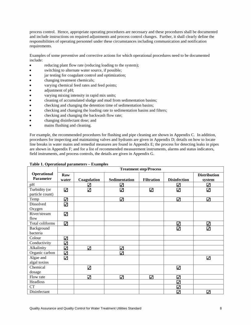
process control. Hence, appropriate operating procedures are necessary and these procedures shall be documented and include instructions on required adjustments and process control changes. Further, it shall clearly define the responsibilities of operating personnel under these circumstances including communication and notification requirements. Examples of some preventive and corrective actions for which operational procedures need to be documented include: • reducing plant flow rate (reducing loading to the system); • switching to alternate water source, if possible; • jar testing for coagulant control and optimization; • changing treatment chemicals; • varying chemical feed rates and feed points; • adjustment of pH; • varying mixing intensity in rapid mix units; • cleaning of accumulated sludge and mud from sedimentation basins; • checking and changing the detention time of sedimentation basins; • checking and changing the loading rate to sedimentation basins and filters; • checking and changing the backwash flow rate; • changing disinfectant dose; and • mains flushing and cleaning. For example, the recommended procedures for flushing and pipe cleaning are shown in Appendix C. In addition, procedures for inspecting and maintaining valves and hydrants are given in Appendix D; details on how to locate line breaks in water mains and remedial measures are found in Appendix E; the process for detecting leaks in pipes are shown in Appendix F; and for a list of recommended measurement instruments, alarms and status indicators, field instruments, and process controls, the details are given in Appendix G. Table 1. Operational parameters – Examples
Operational Parameter
Treatment step/Process Raw
water
Coagulation
Sedimentation
Filtration
Disinfection Distribution
system pH Turbidity (or particle count)
Temp Dissolved Oxygen
River/stream flow
Total coliforms Background bacteria
Colour Conductivity Alkalinity Organic carbon Algae and algal toxins
Chemical dosage
Flow rate Headloss CT Disinfectant
Quality Assurance and Quality Control for Water Treatment Utilities Standard 8

residual Disinfection by-products
Pressure 7. Verification of Treated Water Quality Verification of treated water quality provides an assessment of the performance of the system and the quality of water supplied to the consumers. This incorporates monitoring of treated water quality, which is considered as only one aspect of an overall preventive strategy to assure a safe and reliable drinking water supply to the consumers. It includes sampling and testing performed for assessing compliance with the water quality standards set by the Water Security Agency. Treated water quality monitoring differs from operational monitoring in such a way that it is the minimum (as set in the permit) required by the Water Security Agency and is a legal requirement. Operational monitoring goes beyond what is legally required and involves more in-depth and more frequent checks on the conditions that could affect the treatment. Operational monitoring plan serves as an early warning system whereby process optimization and changes can be implemented before treated water quality compliance is compromised. Key health-related characteristics under treated water quality monitoring include: • microbiological organisms (coliforms); • chemicals used in treatment processes, disinfectant residuals, and any DPBs; • turbidity; and • any health-related characteristic that can be reasonably expected to exceed the guideline value. However, characteristics related to significant aesthetic impacts shall also be monitored. The treated water quality monitoring plan that is to be adopted by all of the water utilities is shown in Appendix H. 8. Emergency Plan An emergency plan ensures the safety of the consumers who use the water from the drinking water system and is generally required in order to meet regulatory requirements. Responding promptly to incidents and emergencies helps to prevent unnecessary problems, protects consumers, and reduces potential contamination of the system and health care cost. Key areas to be addressed in emergency response plan include clearly specified: • response actions; • responsibilities for water treatment plant personnel during emergency situations; • plans for emergency water supplies; and • communication protocols including notification procedure (internal, regulatory, media, and public). Guidance on emergency response planning is available “Waterworks Emergency Planning Standard, EPB-540A” and as a template for community waterworks emergency response, “Example Waterworks Emergency Plan, EPB-241B”. Other related documents are “Water Quality Emergency Planning Standard – An Overview, EPB-541A” and “Water Quality Contingency Planning Standard, EPB-540B”. 9. Training of Water Utility Personnel Certification of water utility operators is mandatory in Saskatchewan. There are typically four classes of water system categories. In Saskatchewan, one or more persons who hold a valid operator certification shall supervise day-to-day operations of waterworks system. This person(s) shall be fully responsible for the operation and maintenance of the facility. The level of operator certification shall match or exceed the classification of the water treatment/distribution facilities. All of the details pertaining to operator certification and training are available in ‘the Saskatchewan Water and Wastewater Works Operator Certification Standards, EPB’ and ‘Available Training and Reading for Water and Wastewater Operators (EPB 149)’. Technological advancements in drinking water treatment system need all the water utility personnel to update their knowledge and skills, which require continuing education. A commitment to conduct/participate in research and development activities is essential to ensure continual improvement. Internal communication is also of prime importance. It is recommended that good communication be maintained among water utility personnel as well as between water utility personnel and regulators.
Quality Assurance and Quality Control for Water Treatment Utilities Standard 9

10. Record Maintenance and Reporting Records are essential for many reasons. They promote the efficiency of water treatment system, remind the operating personnel about their routine operation and maintenance, provide the basic system’s data and operator details and help in the preparation of reports. Precise and comprehensive records are key to an effective maintenance program. Water utility managers and operating personnel need to know what type of information is essential for their system and prepare and record the information accordingly. Further, they shall keep all the relevant information required for the operational and treated water quality monitoring plans. All the records shall bear the signature of the operating personnel in charge of the water treatment system and these records shall be available during the inspection of Environment Officer (EO) or other regulatory personnel.
Quality Assurance and Quality Control for Water Treatment Utilities Standard 10
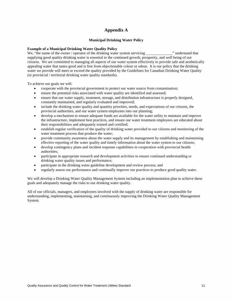
Appendix A
Municipal Drinking Water Policy Example of a Municipal Drinking Water Quality Policy We, “the name of the owner / operator of the drinking water system servicing ______________” understand that supplying good quality drinking water is essential to the continued growth, prosperity, and well being of our citizens. We are committed to managing all aspects of our water system effectively to provide safe and aesthetically appealing water that tastes good and is free from objectionable colour or odour. It is our policy that the drinking water we provide will meet or exceed the quality provided by the Guidelines for Canadian Drinking Water Quality (or provincial / territorial drinking water quality standards). To achieve our goals we will:
• cooperate with the provincial government to protect our water source from contamination; • ensure the potential risks associated with water quality are identified and assessed; • ensure that our water supply, treatment, storage, and distribution infrastructure is properly designed,
constantly maintained, and regularly evaluated and improved; • include the drinking water quality and quantity priorities, needs, and expectations of our citizens, the
provincial authorities, and our water system employees into our planning; • develop a mechanism to ensure adequate funds are available for the water utility to maintain and improve
the infrastructure, implement best practices, and ensure our water treatment employees are educated about their responsibilities and adequately trained and certified;
• establish regular verification of the quality of drinking water provided to our citizens and monitoring of the water treatment process that produce the water;
• provide community awareness about the water supply and its management by establishing and maintaining effective reporting of the water quality and timely information about the water system to our citizens;
• develop contingency plans and incident response capabilities in cooperation with provincial health authorities;
• participate in appropriate research and development activities to ensure continued understanding or drinking water quality issues and performance;
• participate in the drinking water guideline development and review process; and • regularly assess our performance and continually improve our practices to produce good quality water.
We will develop a Drinking Water Quality Management System including an implementation plan to achieve these goals and adequately manage the risks to our drinking water quality. All of our officials, managers, and employees involved with the supply of drinking water are responsible for understanding, implementing, maintaining, and continuously improving the Drinking Water Quality Management System.
Quality Assurance and Quality Control for Water Treatment Utilities Standard 11
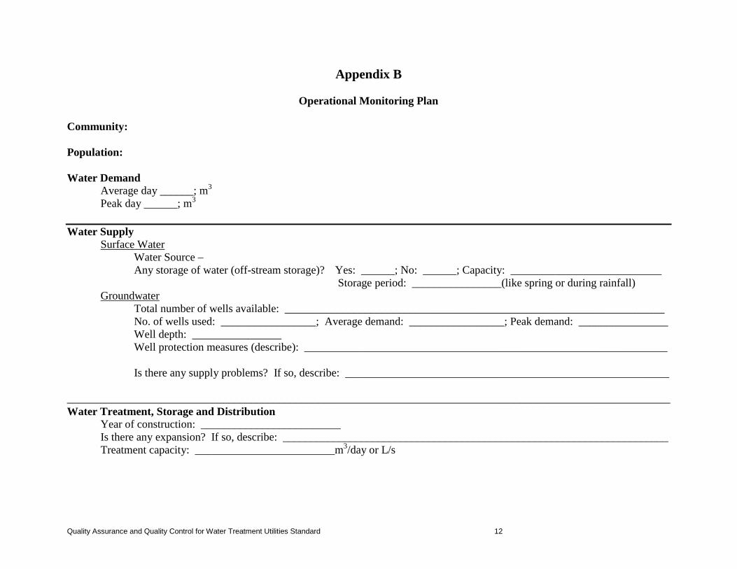
Appendix B
Operational Monitoring Plan Community: Population: Water Demand Average day ______; m3 Peak day ______; m3
Water Supply
Surface Water Water Source – Any storage of water (off-stream storage)? Yes: ______; No: ______; Capacity: ___________________________
Storage period: ________________(like spring or during rainfall) Groundwater
Total number of wells available: ____________________________________________________________________ No. of wells used: _________________; Average demand: _________________; Peak demand: ________________ Well depth: ________________ Well protection measures (describe): _________________________________________________________________
Is there any supply problems? If so, describe: __________________________________________________________
____________________________________________________________________________________________________________ Water Treatment, Storage and Distribution
Year of construction: _________________________ Is there any expansion? If so, describe: _____________________________________________________________________ Treatment capacity: _________________________m3/day or L/s
Quality Assurance and Quality Control for Water Treatment Utilities Standard 12
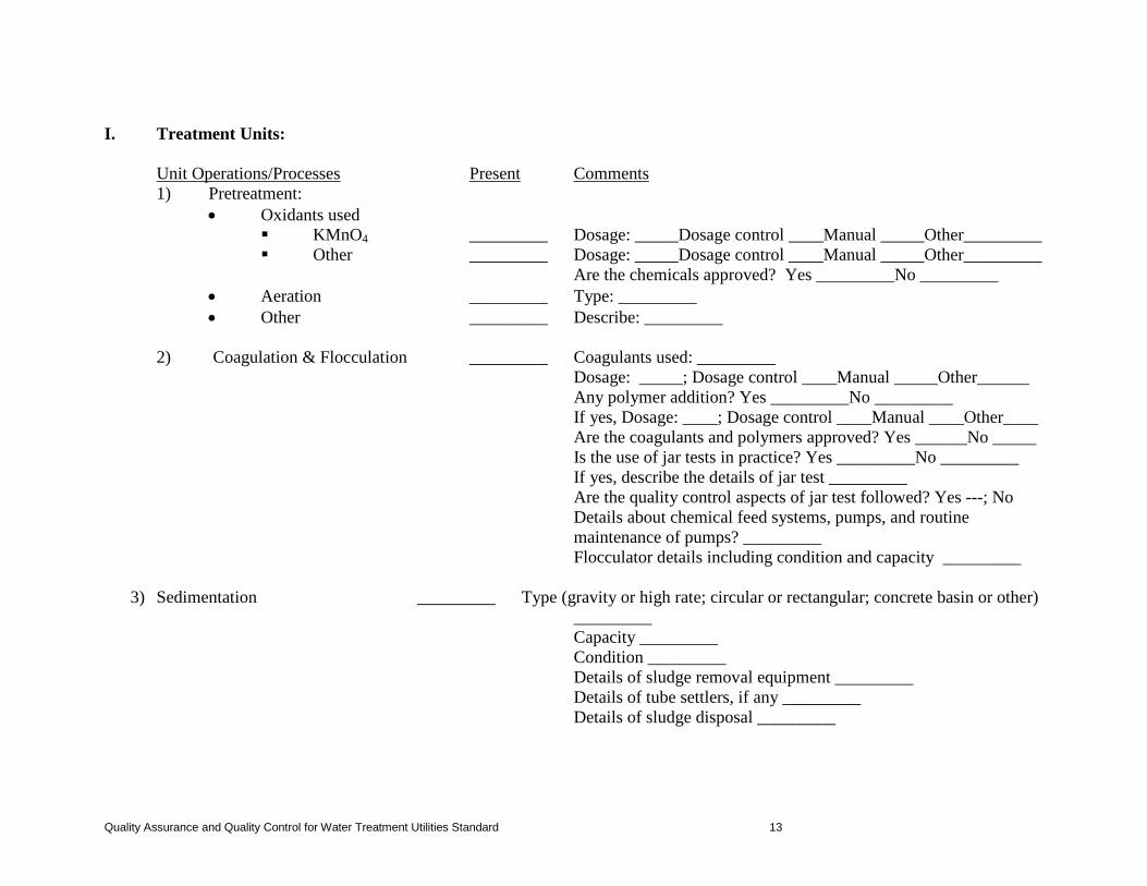
I. Treatment Units:
Unit Operations/Processes Present Comments
1) Pretreatment: • Oxidants used
KMnO4 _________ Dosage: _____Dosage control ____Manual _____Other_________ Other _________ Dosage: _____Dosage control ____Manual _____Other_________
Are the chemicals approved? Yes _________No _________ • Aeration _________ Type: _________ • Other _________ Describe: _________
2) Coagulation & Flocculation _________ Coagulants used: _________
Dosage: _____; Dosage control ____Manual _____Other______ Any polymer addition? Yes _________No _________ If yes, Dosage: ____; Dosage control ____Manual ____Other____ Are the coagulants and polymers approved? Yes ______No _____ Is the use of jar tests in practice? Yes _________No _________ If yes, describe the details of jar test _________ Are the quality control aspects of jar test followed? Yes ---; No
Details about chemical feed systems, pumps, and routine maintenance of pumps? _________
Flocculator details including condition and capacity _________
3) Sedimentation _________ Type (gravity or high rate; circular or rectangular; concrete basin or other) _________
Capacity _________ Condition _________ Details of sludge removal equipment _________ Details of tube settlers, if any _________ Details of sludge disposal _________
Quality Assurance and Quality Control for Water Treatment Utilities Standard 13
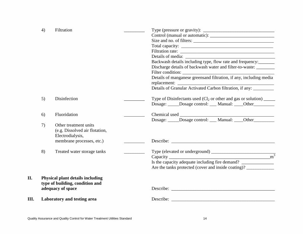
4) Filtration _________ Type (pressure or gravity): _______________________________ Control (manual or automatic): ____________________________ Size and no. of filters: ___________________________________ Total capacity: ________________________________________ Filtration rate: _________________________________________ Details of media: _______________________________________ Backwash details including type, flow rate and frequency:_______ Discharge details of backwash water and filter-to-waste: ________
Filter condition: ________________________________________ Details of manganese greensand filtration, if any, including media replacement: __________________________________________ Details of Granular Activated Carbon filtration, if any: _________
5) Disinfection _________ Type of Disinfectants used (Cl2 or other and gas or solution) _____
Dosage: _____Dosage control: ___ Manual: ____Other_________
6) Fluoridation _________ Chemical used _________________________________________ Dosage: _____Dosage control: ___ Manual: ____Other_________
7) Other treatment units (e.g. Dissolved air flotation, Electrodialysis, membrane processes, etc.) _________ Describe: _____________________________________________ 8) Treated water storage tanks _________ Type (elevated or underground) ____________________________
Capacity ____________________________________________m3 Is the capacity adequate including fire demand? ______________ Are the tanks protected (cover and inside coating)? ____________
II. Physical plant details including type of building, condition and
adequacy of space Describe: _____________________________________________ III. Laboratory and testing area Describe: _____________________________________________
Quality Assurance and Quality Control for Water Treatment Utilities Standard 14
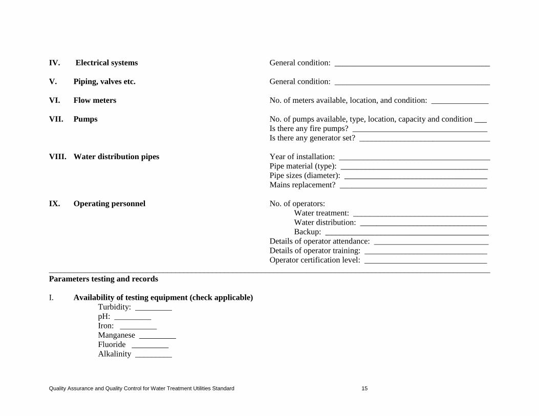
IV. Electrical systems General condition: ______________________________________
V. Piping, valves etc. General condition: ______________________________________
VI. Flow meters No. of meters available, location, and condition: ______________
VII. Pumps No. of pumps available, type, location, capacity and condition ___
Is there any fire pumps? _________________________________ Is there any generator set? ________________________________
VIII. Water distribution pipes Year of installation: _____________________________________ Pipe material (type): ____________________________________ Pipe sizes (diameter): ___________________________________ Mains replacement? ____________________________________
IX. Operating personnel No. of operators: Water treatment: _________________________________ Water distribution: _______________________________ Backup: ________________________________________ Details of operator attendance: ____________________________ Details of operator training: ______________________________ Operator certification level: ______________________________ ____________________________________________________________________________________________________________ Parameters testing and records I. Availability of testing equipment (check applicable) Turbidity: _________ pH: _________ Iron: _________ Manganese _________ Fluoride _________ Alkalinity _________
Quality Assurance and Quality Control for Water Treatment Utilities Standard 15
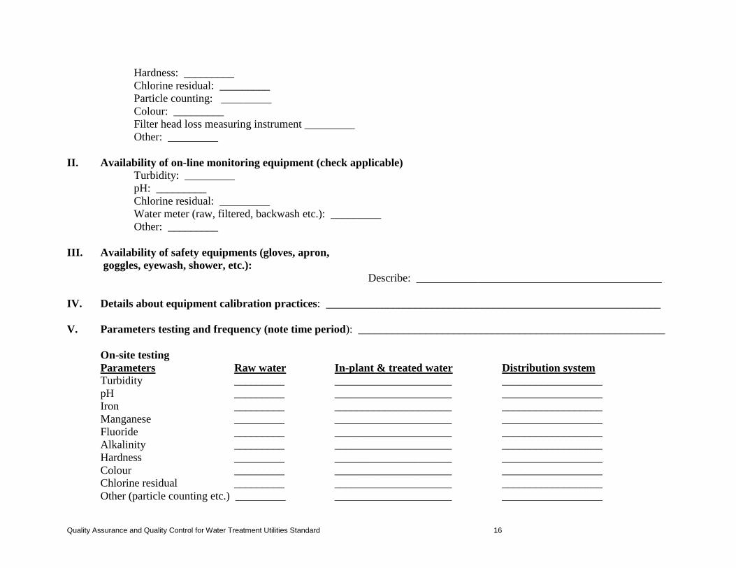
Hardness: _________ Chlorine residual: _________ Particle counting: _________ Colour: _________ Filter head loss measuring instrument _________ Other: _________ II. Availability of on-line monitoring equipment (check applicable) Turbidity: _________ pH: _________ Chlorine residual: _________ Water meter (raw, filtered, backwash etc.): _________ Other: _________ III. Availability of safety equipments (gloves, apron, goggles, eyewash, shower, etc.): Describe: ____________________________________________ IV. Details about equipment calibration practices: ____________________________________________________________ V. Parameters testing and frequency (note time period): _______________________________________________________ On-site testing Parameters Raw water In-plant & treated water Distribution system Turbidity _________ _____________________ __________________ pH _________ _____________________ __________________ Iron _________ _____________________ __________________ Manganese _________ _____________________ __________________ Fluoride _________ _____________________ __________________ Alkalinity _________ _____________________ __________________ Hardness _________ _____________________ __________________ Colour _________ _____________________ __________________ Chlorine residual _________ _____________________ __________________ Other (particle counting etc.) _________ _____________________ __________________
Quality Assurance and Quality Control for Water Treatment Utilities Standard 16
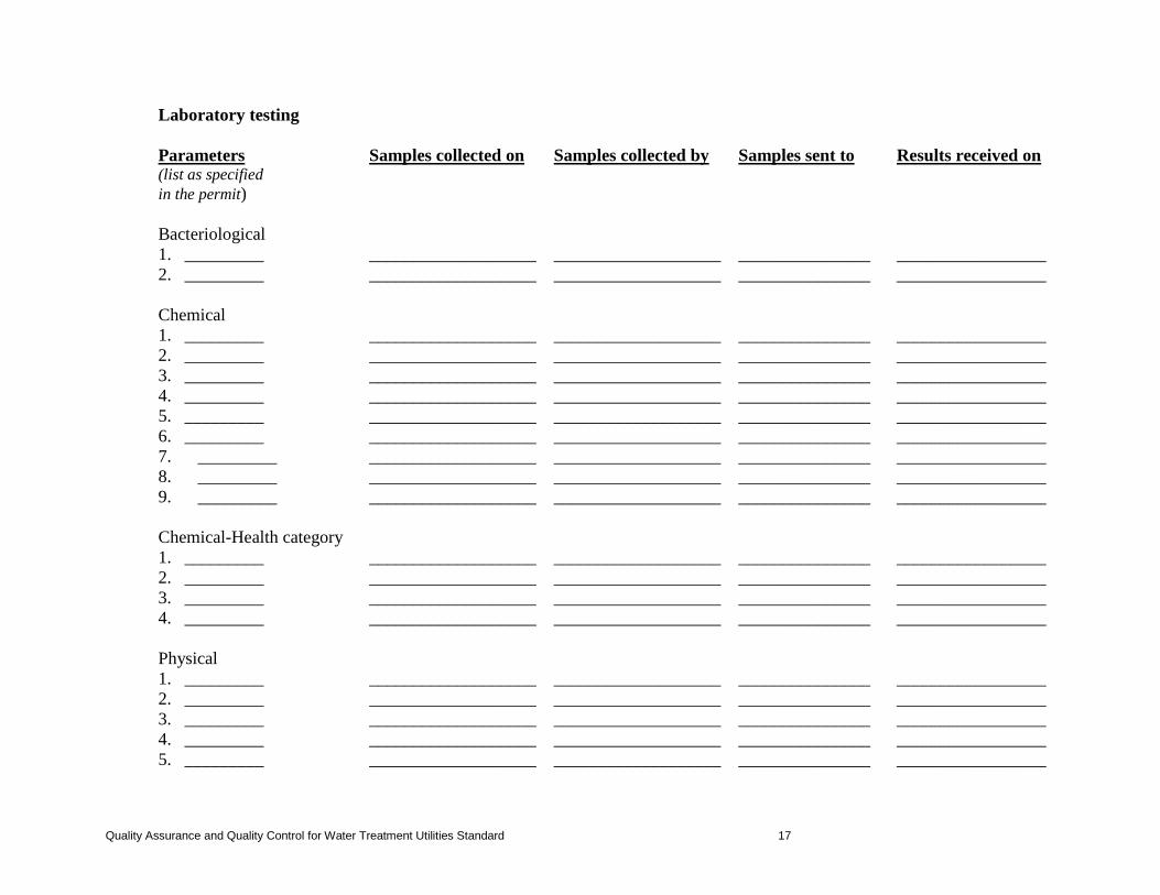
Laboratory testing Parameters Samples collected on Samples collected by Samples sent to Results received on
(list as specified in the permit)
Bacteriological
1. _________ ___________________ ___________________ _______________ _________________ 2. _________ ___________________ ___________________ _______________ _________________ Chemical 1. _________ ___________________ ___________________ _______________ _________________ 2. _________ ___________________ ___________________ _______________ _________________ 3. _________ ___________________ ___________________ _______________ _________________ 4. _________ ___________________ ___________________ _______________ _________________ 5. _________ ___________________ ___________________ _______________ _________________ 6. _________ ___________________ ___________________ _______________ _________________ 7. _________ ___________________ ___________________ _______________ _________________ 8. _________ ___________________ ___________________ _______________ _________________ 9. _________ ___________________ ___________________ _______________ _________________ Chemical-Health category 1. _________ ___________________ ___________________ _______________ _________________ 2. _________ ___________________ ___________________ _______________ _________________ 3. _________ ___________________ ___________________ _______________ _________________ 4. _________ ___________________ ___________________ _______________ _________________ Physical 1. _________ ___________________ ___________________ _______________ _________________ 2. _________ ___________________ ___________________ _______________ _________________ 3. _________ ___________________ ___________________ _______________ _________________ 4. _________ ___________________ ___________________ _______________ _________________ 5. _________ ___________________ ___________________ _______________ _________________
Quality Assurance and Quality Control for Water Treatment Utilities Standard 17
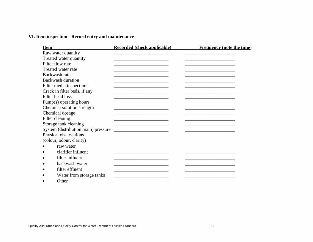
VI. Item inspection - Record entry and maintenance
Item Recorded (check applicable) Frequency (note the time) Raw water quantity _______________________ _____________________ Treated water quantity _______________________ _____________________ Filter flow rate _______________________ _____________________ Treated water rate _______________________ _____________________ Backwash rate _______________________ _____________________ Backwash duration _______________________ _____________________ Filter media inspections _______________________ _____________________ Crack in filter beds, if any _______________________ _____________________
Filter head loss _______________________ _____________________ Pump(s) operating hours _______________________ _____________________ Chemical solution strength _______________________ _____________________ Chemical dosage _______________________ _____________________ Filter cleaning _______________________ _____________________ Storage tank cleaning _______________________ _____________________ System (distribution main) pressure _______________________ _____________________ Physical observations (colour, odour, clarity) • raw water _______________________ _____________________ • clarifier influent _______________________ _____________________ • filter influent _______________________ _____________________ • backwash water _______________________ _____________________ • filter effluent _______________________ _____________________ • Water from storage tanks _______________________ _____________________ • Other _______________________ _____________________
Quality Assurance and Quality Control for Water Treatment Utilities Standard 18
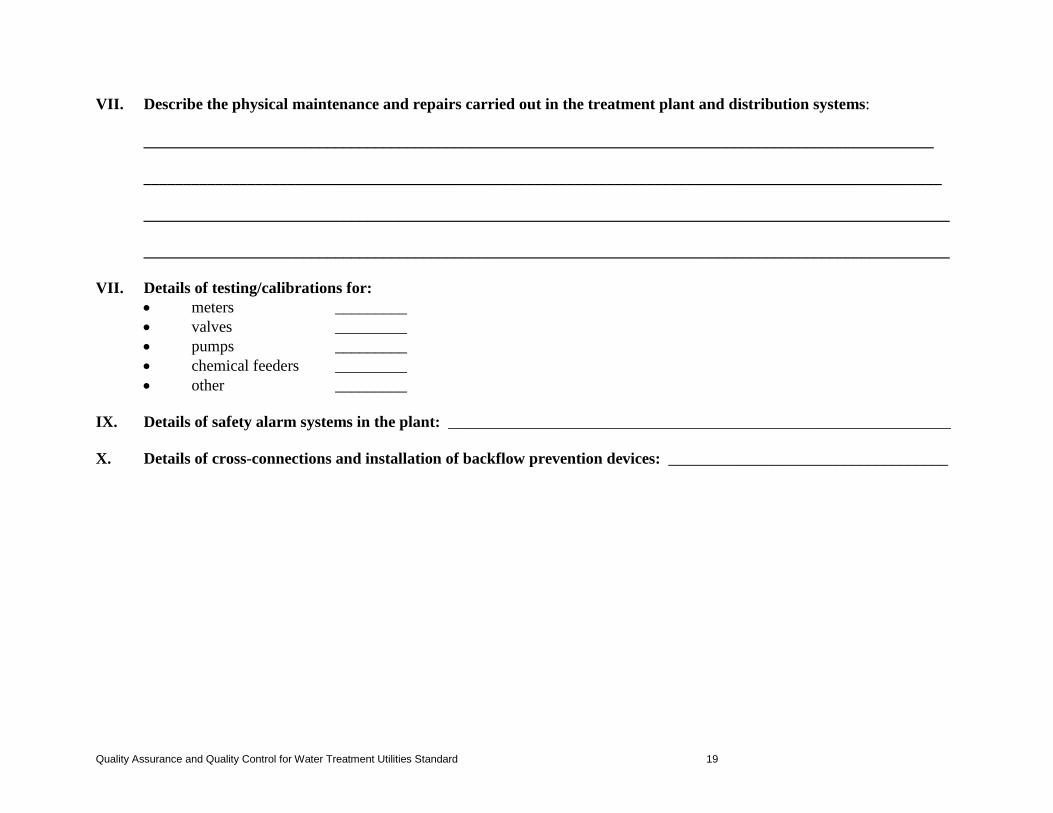
VII. Describe the physical maintenance and repairs carried out in the treatment plant and distribution systems: ___________________________________________________________________________________________________ ____________________________________________________________________________________________________ _____________________________________________________________________________________________________ _____________________________________________________________________________________________________ VII. Details of testing/calibrations for:
• meters _________ • valves _________ • pumps _________ • chemical feeders _________ • other _________
IX. Details of safety alarm systems in the plant: _______________________________________________________________ X. Details of cross-connections and installation of backflow prevention devices: ___________________________________
Quality Assurance and Quality Control for Water Treatment Utilities Standard 19
Appendix C
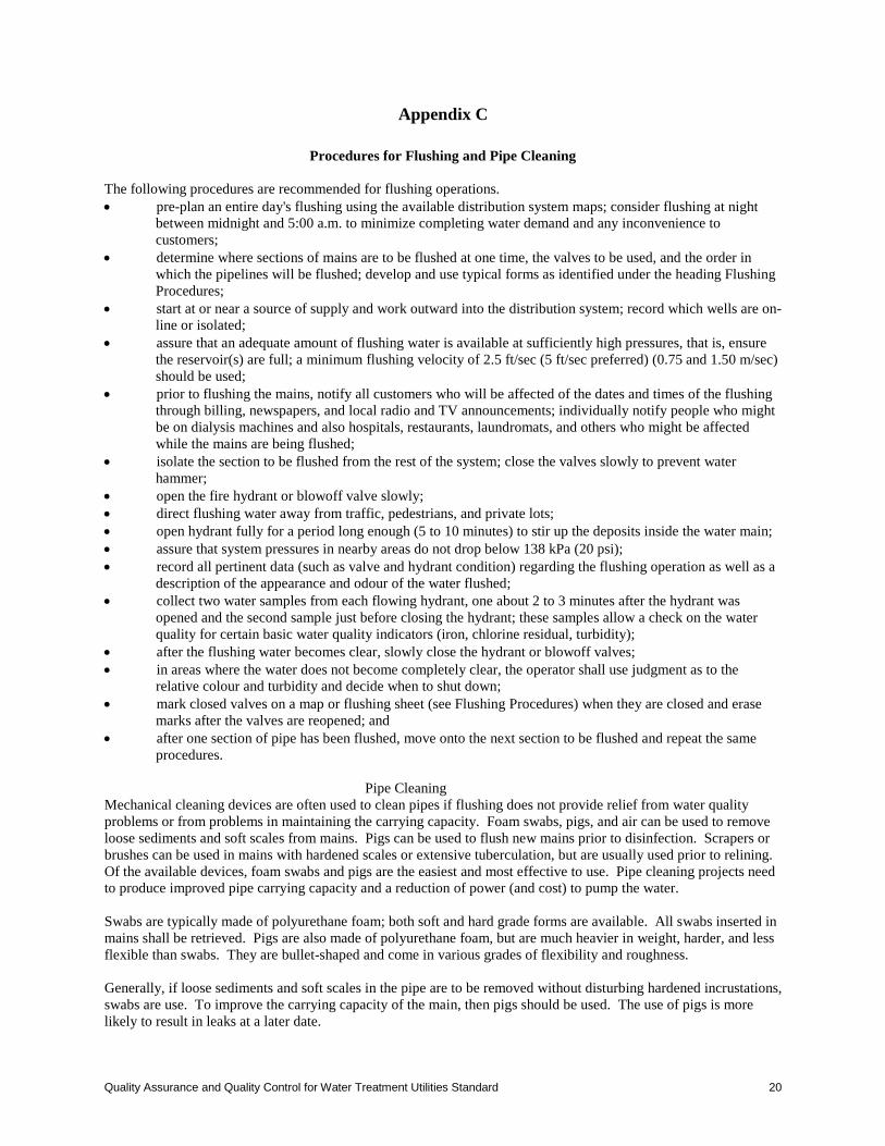
Procedures for Flushing and Pipe Cleaning The following procedures are recommended for flushing operations. • pre-plan an entire day's flushing using the available distribution system maps; consider flushing at night
between midnight and 5:00 a.m. to minimize completing water demand and any inconvenience to customers;
• determine where sections of mains are to be flushed at one time, the valves to be used, and the order in which the pipelines will be flushed; develop and use typical forms as identified under the heading Flushing Procedures;
• start at or near a source of supply and work outward into the distribution system; record which wells are on-line or isolated;
• assure that an adequate amount of flushing water is available at sufficiently high pressures, that is, ensure the reservoir(s) are full; a minimum flushing velocity of 2.5 ft/sec (5 ft/sec preferred) (0.75 and 1.50 m/sec) should be used;
• prior to flushing the mains, notify all customers who will be affected of the dates and times of the flushing through billing, newspapers, and local radio and TV announcements; individually notify people who might be on dialysis machines and also hospitals, restaurants, laundromats, and others who might be affected while the mains are being flushed;
• isolate the section to be flushed from the rest of the system; close the valves slowly to prevent water hammer;
• open the fire hydrant or blowoff valve slowly; • direct flushing water away from traffic, pedestrians, and private lots; • open hydrant fully for a period long enough (5 to 10 minutes) to stir up the deposits inside the water main; • assure that system pressures in nearby areas do not drop below 138 kPa (20 psi); • record all pertinent data (such as valve and hydrant condition) regarding the flushing operation as well as a
description of the appearance and odour of the water flushed; • collect two water samples from each flowing hydrant, one about 2 to 3 minutes after the hydrant was
opened and the second sample just before closing the hydrant; these samples allow a check on the water quality for certain basic water quality indicators (iron, chlorine residual, turbidity);
• after the flushing water becomes clear, slowly close the hydrant or blowoff valves; • in areas where the water does not become completely clear, the operator shall use judgment as to the
relative colour and turbidity and decide when to shut down; • mark closed valves on a map or flushing sheet (see Flushing Procedures) when they are closed and erase
marks after the valves are reopened; and • after one section of pipe has been flushed, move onto the next section to be flushed and repeat the same
procedures. Pipe Cleaning
Mechanical cleaning devices are often used to clean pipes if flushing does not provide relief from water quality problems or from problems in maintaining the carrying capacity. Foam swabs, pigs, and air can be used to remove loose sediments and soft scales from mains. Pigs can be used to flush new mains prior to disinfection. Scrapers or brushes can be used in mains with hardened scales or extensive tuberculation, but are usually used prior to relining. Of the available devices, foam swabs and pigs are the easiest and most effective to use. Pipe cleaning projects need to produce improved pipe carrying capacity and a reduction of power (and cost) to pump the water. Swabs are typically made of polyurethane foam; both soft and hard grade forms are available. All swabs inserted in mains shall be retrieved. Pigs are also made of polyurethane foam, but are much heavier in weight, harder, and less flexible than swabs. They are bullet-shaped and come in various grades of flexibility and roughness. Generally, if loose sediments and soft scales in the pipe are to be removed without disturbing hardened incrustations, swabs are use. To improve the carrying capacity of the main, then pigs should be used. The use of pigs is more likely to result in leaks at a later date.
Quality Assurance and Quality Control for Water Treatment Utilities Standard 20
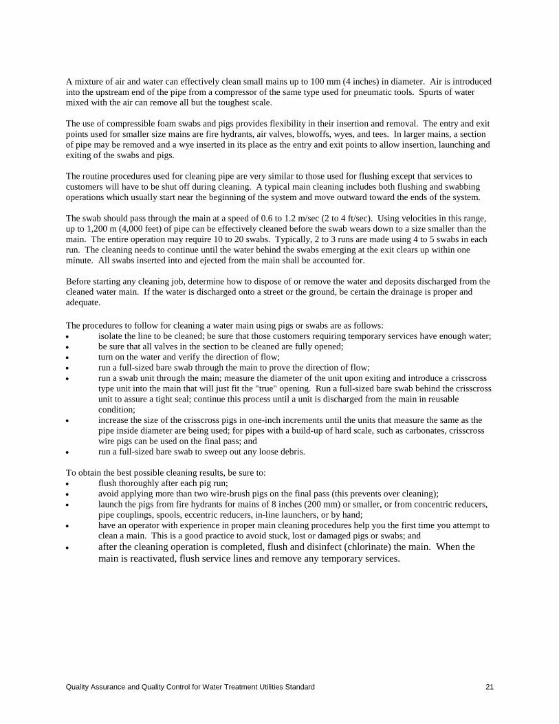
A mixture of air and water can effectively clean small mains up to 100 mm (4 inches) in diameter. Air is introduced into the upstream end of the pipe from a compressor of the same type used for pneumatic tools. Spurts of water mixed with the air can remove all but the toughest scale. The use of compressible foam swabs and pigs provides flexibility in their insertion and removal. The entry and exit points used for smaller size mains are fire hydrants, air valves, blowoffs, wyes, and tees. In larger mains, a section of pipe may be removed and a wye inserted in its place as the entry and exit points to allow insertion, launching and exiting of the swabs and pigs. The routine procedures used for cleaning pipe are very similar to those used for flushing except that services to customers will have to be shut off during cleaning. A typical main cleaning includes both flushing and swabbing operations which usually start near the beginning of the system and move outward toward the ends of the system. The swab should pass through the main at a speed of 0.6 to 1.2 m/sec (2 to 4 ft/sec). Using velocities in this range, up to 1,200 m (4,000 feet) of pipe can be effectively cleaned before the swab wears down to a size smaller than the main. The entire operation may require 10 to 20 swabs. Typically, 2 to 3 runs are made using 4 to 5 swabs in each run. The cleaning needs to continue until the water behind the swabs emerging at the exit clears up within one minute. All swabs inserted into and ejected from the main shall be accounted for. Before starting any cleaning job, determine how to dispose of or remove the water and deposits discharged from the cleaned water main. If the water is discharged onto a street or the ground, be certain the drainage is proper and adequate. The procedures to follow for cleaning a water main using pigs or swabs are as follows: • isolate the line to be cleaned; be sure that those customers requiring temporary services have enough water; • be sure that all valves in the section to be cleaned are fully opened; • turn on the water and verify the direction of flow; • run a full-sized bare swab through the main to prove the direction of flow; • run a swab unit through the main; measure the diameter of the unit upon exiting and introduce a crisscross
type unit into the main that will just fit the "true" opening. Run a full-sized bare swab behind the crisscross unit to assure a tight seal; continue this process until a unit is discharged from the main in reusable condition;
• increase the size of the crisscross pigs in one-inch increments until the units that measure the same as the pipe inside diameter are being used; for pipes with a build-up of hard scale, such as carbonates, crisscross wire pigs can be used on the final pass; and
• run a full-sized bare swab to sweep out any loose debris. To obtain the best possible cleaning results, be sure to: • flush thoroughly after each pig run; • avoid applying more than two wire-brush pigs on the final pass (this prevents over cleaning); • launch the pigs from fire hydrants for mains of 8 inches (200 mm) or smaller, or from concentric reducers,
pipe couplings, spools, eccentric reducers, in-line launchers, or by hand; • have an operator with experience in proper main cleaning procedures help you the first time you attempt to
clean a main. This is a good practice to avoid stuck, lost or damaged pigs or swabs; and • after the cleaning operation is completed, flush and disinfect (chlorinate) the main. When the
main is reactivated, flush service lines and remove any temporary services.
Quality Assurance and Quality Control for Water Treatment Utilities Standard 21
Appendix D
Procedures for Inspecting and Maintaining Valves and Hydrants
Procedures for Valves
Routine valve inspections shall be conducted by performing the following tasks: • verify the accuracy of the location of the valve boxes on the system map (if incorrect, change the map and
update the Master Copy); • after removing the valve box cover, inspect the stem and nut for damage or obvious leakage; • close the valve fully and record the number of turns to the fully closed position. Always close a valve
slowly to prevent water hammer; • reopen the valve to re-establish system flows; and • clean valve box cover seat; sometimes covers on valve boxes will come off when traffic passes over them
due to dirt in the seat. Exercising (opening and closing a valve) shall be done at the same time the valve inspection is made. Some manufacturers recommend that a valve stem never be left in a fully open or closed position. They recommend that after fully opening or closing a valve, back off the stem by one turn. Conditions of each system will determine how often the valves needs to be exercised, in general, it is recommended that all valves be exercised at least once a year. Planned exercising of valves verifies valve location, determines whether or not the valve works, and extends valve life by helping to clean incrustations from the valve seats and gates. Any valves which do not completely close or open shall be replaced. Valves which leak around the stems need to be repacked. To determine that a valve is closed, an aquaphone or other listening device can be used. Valves need to be exercised in both directions (fully closed and fully opened) and the number of turns and direction of operation recorded. Valves operating in a direction opposite to that which is standard for the system need to be identified and this fact recorded. The condition of the valve packing, stem, stem nut, and gearing shall be noted. A timely maintenance program needs to be initiated to correct any problems found during the inspection and exercising. An important factor in maintaining distribution system valves are the availability of current and correct maps of the distribution system. Each utility needs to verify their maps often so that it is accurate, and keep the map up to date by immediately recording any changes such as replacements or additions. Some water purveyors equip their service trucks with "gate books" which carry all of the pertinent valve information including location, direction of turning to close, and number of turns required. Maintaining current records is as important as maintaining current maps. A purveyor needs to develop a valve form to track important information. The location of a valve is obtained from a controlled survey bench mark or permanent reference point. The make of valve is important because different makes have different operating characteristics. The use of a simple valve numbering system keyed to up-to-date drawings is recommended. This procedure has proven to be quite helpful in locating valves rapidly and in communicating with others about particular valves. Road improvements require constant attention from water distribution system operators to ensure that valves are not lost. Valve boxes can be graded out or covered with pavement. The centre lines of roads, curb lines, and right-of-way lines are not to be used as reference points for locating valves, because they can change over time. Valves left closed in error can cause severe problems in a distribution system. Construction and maintenance crews operate valves as they do their work, and contractors and plumbers may operate valves without permission. Separate pressure zones in distribution systems may be established by closing valves, thus increasing the possibility of problems related to the incorrect use of valves. Unexplained problems with pressure and excessive operation of pumps in a given area have been traced to valves left closed or open in error. When crews change shifts during a project, valve closure and opening information shall be exchanged. Crew chiefs shall be certain all valves are restored to proper positions.
Quality Assurance and Quality Control for Water Treatment Utilities Standard 22
Proper advance planning is important. The valves that will be used to isolate a damaged valve shall be in good operating condition. When ordering repair parts, include the size, make, direction of opening, year of manufacture, and other pertinent information in order to assure that the correct repair parts will be received. Until the valve is isolated and opened up, it is difficult to determine what part of the valve is damaged. Therefore, have all replacement parts available before isolating the necessary section of the water main, excavating the valve, and making the repairs.
Procedures for Fire Hydrants Operators responsible for hydrant inspections need to be familiar with the various types of hydrants used in their system. There are two basic types of fire hydrants, the dry barrel and wet barrel. A hydrant has four principal parts: the inlet pipe which is connected to the main water supply, the main valve, the barrel and the head. The supplier should be contacted whenever necessary to obtain descriptive literature, operation and maintenance instructions, parts manuals or assistance on particular problems. In general, fire hydrants need to be inspected and maintained twice a year. These operations are often done in the spring and the fall. However, each hydrant needs to also be inspected after each use. Inspect dry-barrel hydrants after use, especially during freezing weather, to assure that the drain remains open when the hydrant is not in use. An additional source of information on fire hydrants is AWWA's Manual M17, Installation, Field Testing, and Maintenance of Fire Hydrants. Some general inspection and maintenance procedures used for hydrants include: • inspect for leakage and make corrections when necessary; • open hydrant fully, checking; • ease of operation; • flush hydrant to waste (take care for to direct flow); • remove all nozzle caps and inspect for thread nozzle and cap threads; • clean and lubricate outlet nozzle threads. • replace caps, tighten with a spanner wrench, then back off on the threads slightly so that the caps will not
be excessively tight but will leave sufficient frictional resistance to prevent removal by hand; • check for any exterior obstruction that could interfere with hydrant operation during an emergency; • check dry-barrel hydrants for proper drainage; • clean exterior of hydrant and repaint if necessary; • be sure that the auxiliary valve is in the fully opened position; • if a hydrant is inoperable, tag it with a clearly visible marking and immediately report the condition of this
fire hydrant to your fire department; and • prepare a record of your inspection and maintenance operations and any repair work. Hydrants can be partially protected against freezing by covering them with a box which can be quickly removed when the hydrant shall be used. To keep hydrants from freezing (those that won't drain in the winter due to frozen conditions), insert in the hydrant propylene glycol or some other non toxic NSF approved substance that won't freeze or cause water quality problems. Frozen hydrants may be thawed using electric current thawing or live steam injected through a hose into the hydrant barrel. Standardization of hydrants minimizes the requirement for stocking parts, simplifies repair procedures, and allows replacing only defective parts. Every water purveyor needs to keep a basic stock of repair parts on hand for immediate use. Fire hydrants are usually the only part of the distribution system regularly seen by the general public. Frequent painting of hydrants creates a favourable impression and is, therefore, a public relations tool. Fire hydrant caps or guards can be installed on the tops of fire hydrants to eliminate fire hydrant vandalism.
Quality Assurance and Quality Control for Water Treatment Utilities Standard 23
Appendix E
Locating and Remediating Line Breaks Breaks in water mains can occur at any time and every purveyor shall have an established, written response plan. After a break has been located, determine which valves must be closed to isolate the break. A good policy before shutting off any valves is to notify every consumer involved that they will be out of water for an estimated length of time. The purpose of this advance notification is to allow consumers to make any necessary preparations. If extensive damage is caused by the break (flooding and/or washouts), close the valves and isolate the section as soon as possible, even before notifying all consumers. After the valves are closed, a trash pump can be used to drain the hole. A backhoe or other equipment can be used to dig down to the break. Before entering the hole, determine the necessary shoring needed. Use the appropriate shoring. Remove the damaged section of pipe and as much silt and debris as possible from the remaining sections of the main by flushing or other methods. Replace the damaged section of pipe and/or valves using clamps and other fittings. Flush the entire section which was isolated using hydrants or drains. Disinfect the system by following the recommended standards for disinfecting mains. All new or repaired watermains must be disinfected according to the current edition of the AWWA Standard for Disinfecting Water Mains Standard C651-05. New lines shall be thoroughly flushed and chlorinated at a dosage of in accordance with C651-05. In short lines, and if portable chlorination equipment is not available, thorough flushing and maintenance of a free chlorine residual of 1.0 mg/L after 24 hours shall be carried out, with a test for residual chlorine being made at the end of the test period.
Appendix F
Processes for Detecting Leaks Leaks may originate from any weakened joint or fitting connection or from a damaged or corroded part of the pipe. Leaks are undesirable not only because they waste water, but because they can undermine pavements and other structures. Another undesirable effect of leaks is that the leak soaks the ground surrounding the pipe and in the event that pressure is lost in the pipe, the water, combined now with dirt and other contaminants, may backflow into the pipe. The total amount of leakage is also affected by the type of soil surrounding the leaking pipes. In coarse soils (sands) the leakage may continue for an extended period without detection, whereas in finer soils (clays) leaks are detected sooner on the surface. The process of locating a leak can be difficult and can become a troublesome and frustrating experience. Methods used to locate leaks include direct observation as well as use of sounding rods, listening devices, and data from a waste control study. The simplest method of leak detection is to search for and locate wet spots which might indicate the presence of a leak. Sometimes these are reported by the system's customers. However, even if a damp spot is found, it does not necessarily mean the leak can be easily found. The leak may be located directly below the damp area or it may be metres away. Often the leak is not located where it would be expected because water follows the path of least resistance to the ground surface. After the general location of the leak has been determined, a probe may be used to find the exact location. This probe is a sharp-pointed metal rod that is thrust into the ground and pulled up for inspection. If the rod is moist or muddy, the line of the leak is being followed. Do not probe into an area that has an electrical cable.
Quality Assurance and Quality Control for Water Treatment Utilities Standard 24
Listening devices are sound-intensifying equipment that is used in a systematic fashion to locate leaks. The simplest listening device is a steel bar held against the pipe or valve. The device is moved in the direction of increasing sound until the leak is found. Patented leak detectors use audiophones to pick up the sound of escaping water. Another method for locating leaks is the use of a leak noise correlator. This instrument locates leaks by noise intensity and the time it takes for the leak sound to travel to a pair of microphones placed on fittings (fire hydrants or stop valves) on each side of a suspected leak. Leak correlators are fairly accurate in locating a leak. The amount of water lost from the distribution system through leakage is only one component of the system's total water losses. The total amount of water lost from a distribution system from all sources is often referred to as "unaccounted for water" or non-revenue water (NRW). The NRW is the difference between the total amount of water produced and the total amount of water consumed. The amount of unaccounted for water lost by a distribution system is usually determined by conducting a water audit. Waste control or water audit studies are usually conducted when no specific reason can be found for a significant water loss in the system. Routine comparisons of water production and use needs to be made to determine the amount of NRW or unaccounted for water. When the loss exceeds 10 percent of the water produced corrective actions needs to be taken.
Appendix G
List of Measurements, Alarms, Status Indicators, etc. For plants of 1 ML/d (220,000 igpd) capacity and greater, the following instruments should be provided as a minimum for the relevant processes listed. Raw Water Instrumentation: • low-level switches to shut down the raw water pumps. These should be hard-wired to the starters; • running and trip indication for raw water pumps; and • raw water turbidity, pH, pressure, flow rate, and flow volume. Rapid Mixer: • running and trip indication. Flocculators: • running and trip indication; and • speed (if variable speed type). Solids Contact Clarifiers: • recirculator speed indication; • running and trip indication; • level indication; • blow down valve status; and • turbidity and pH following clarification. Softening: • if lime softening is used, pH following recarbonation; and • recarbonation CO2 feed status. Filter Instrumentation: • turbidity on each individual filter effluent and filter to waste. This can be a single instrument for each filter
if piping arrangement permits; • for constant rate filters: differential head loss across the filter media; • filter flow rate;
Quality Assurance and Quality Control for Water Treatment Utilities Standard 25

• where the backwash sequence is automated, provide open and close limit switches or position on all filter valves and status on backwash equipment; and
• filter run time. Backwash Instrumentation: • running and trip indication for backwash pump(s); • running and trip indication for air blowers (if air scour is used); • backwash flow rate and flow total; and • elapsed time since last backwash. Clearwell and Distribution Pump Instrumentation: • level indication for clearwell and other tanks; • running and trip indication for the distribution pumps; • low-level switches to shut down the distribution pumps. These should be hard-wired to the motor starters; • turbidity, chlorine residual, fluoride residual (if fluoridation is practised), pH, pressure, flow rate, and flow
total on plant discharge; • for variable speed pumps, indicate the pump speed. Chemical Systems: • running and trip indication for chemical loading, batching and pumping equipment; • low and high level alarms in storage bins, silos or tanks; • level indication for tanks; • weigh scales for hydrofluosilicic acid day tanks or storage if no day tank is used; • weigh scales for gaseous feed chemicals such as chlorine or sulphur dioxide; • speed indication on variable speed pumps; • rotameters (or other flow monitoring device) for carrier water feed systems; and • chemical feed flow rate is desirable but not mandatory. Miscellaneous Instrumentation: • run time meters on all pumps and major electrically driven equipment; • speed, run time, oil pressure and temperature gauges, fault signal switches and manual start and shut down
on engines; • where the plant is automated or operated remotely from either within the plant or outside, provide open and
close limit switches or position indicators on all major valves, status on all major equipment and security instruments including door switches, building temperature switches and smoke alarms; and
• any additional instrumentation recommended by equipment manufacturers. Alarms and Status Indication As a minimum, the following alarms need to be provided: • high turbidity on the raw water, clarifier effluent (if applicable), filter effluent, and plant discharge; • high and low pressure on the raw water line; • high flow rate on the raw water line. • high and low level in clarifiers or flocculators; • high torque on solids contact clarifier recirculator and rake; • high torque on flocculators; • high level in filters; • high and low level in chemical storage tanks; • high and low chemical feed rates (if measurement is provided); • high flow rate on each filter individually (also low flow rate on declining rate filters); • high and low levels in each clearwell, pumpwell, and reservoir; • high and low pH on the raw and treated water (if on-line measurements are provided); • high and low chlorine residual on the plant discharge (where online measurements are provided); • high head loss on the filters (if constant rate type); • trip or failure to run on each pump; • high and low pressure on the plant discharge line; • high flow rate on the plant discharge line;
Quality Assurance and Quality Control for Water Treatment Utilities Standard 26
• chlorine gas detection in the chlorine storage rooms; • chlorine scale low weight (where scales are equipped with transmitters); and • valve operation failure (where valves are provided with limit switches. Field Instruments
Level Instruments Where access to the top of the reservoir is convenient (such as in a clearwell), an ultrasonic level transmitter should be used. Where access to the bottom of the reservoir is convenient (such as at a tower or above-ground reservoir), a pressure transmitter can be used.
Flow Instruments On-line flow meters should generally be one of the following types: • turbine (or nutating disk); • magnetic; and • ultrasonic (either transit-time or Doppler). All of these types of instruments can be equipped to provide both flow rate and flow total measurements. Price, line size, flow rate, flow range, pipe material, required accuracy, and water quality will dictate the selection of the type of instrument.
Water Quality Instruments The most frequently used water quality measurements are turbidity, pH, and chlorine residual. On-line turbidity measurement is relatively inexpensive and should be provided in any plant, on the raw water, flocculator or clarifier effluent (if applicable), each filter effluent, and final plant discharge lines. In larger plants, on-line pH and chlorine residual are generally used, but manual testing can be done in smaller plants. Process Controls
Pumping Systems Regardless of the function of the pumping system, its control will normally be achieved through monitoring level, flow and/or pressure. The choice of control parameter(s) will depend on the system's function and features. Controls and monitoring for raw water pumping and finished water pumping are normally required.
Treatment Processes Travelling Screens Two methods may be used to control the operation of travelling screens: • simple manual start/stop which requires the presence of the operator to start and stop the screen. This
method is not recommended where sudden changes in raw water quality could result in heavy debris accumulation on the screens; and
• automatic activation by differential level or time. This method uses the differential level across the screen to provide the start condition. Once started, the screen needs to be run at least one "cycle" and stop automatically when the differential level is returned to the clean screen value.
Chemical Feed Systems Liquid/Gas Chemical Feed Basic chemical dose rate control can be achieved by flow pacing (i.e., adjusting chemical feed rate based on the flow of the stream it is to be injected into). This can be achieved using a variable speed metering pump (liquid) or flow control valve (gas) linked to a flowmeter on the receiving stream. For finer dosage adjustment, feed rate can also be controlled based on downstream instrumentation (e.g., residual chlorine analyzer providing feedback signal to chlorine dosing pump).
Quality Assurance and Quality Control for Water Treatment Utilities Standard 27

Dry Chemical Feed Dry chemical feed systems typically include a packaged bulk storage combination feeder and mixer. The feeder can be gravimetric or volumetric, and will be controlled by a 4-20 mA signal from the flow transmitter on the plant flowmeter. Rapid Mixing Control of the rapid mixer will be simply on or off; the unit should operate continuously whenever the plant is in operation. Flocculation Flocculation requirements should be addressed in terms of the unit process parameters. Clarification Careful monitoring and control is most important to successful clarification. Adequate instrumentation to measure water quality parameters (e.g., turbidity) prior to and after clarification is essential. Dissolved Air Flotation (DAF) The process variables in DAF are: • flowrate; • recycle rate; and • float removal cycle. Filtration Two types of filtration are used for water treatment: • rapid gravity filtration; and • slow sand filtration. Rapid Gravity Filtration (RGF) Constant Rate: Flow through a constant rate RGF is controlled by a flow control valve on the filter effluent or by influent flow splitting and filter level control. For the flow control type, the effluent valve position is controlled by a flowrate signal from a flow meter, usually located on the filter effluent. For the level control type, the effluent valve position is controlled by the water level in the filter. A filter run will be terminated, and the bed backwashed, based on one or any of the following: • run time; • headloss across the bed; • effluent turbidity; and • effluent particle count (optional). Declining Rate: Flow through a declining rate RGF is not directly controlled as is the case with constant rate RGF. The rate simply decreases as the filter plugs. An effluent valve with manually adjustable stops is set to ensure the flowrate through a clean bed is not excessive. Once set, this valve will return to the set position after backwash (or after being closed for maintenance, etc.). A filter run will be terminated based on one or any of the following: • run time; • effluent flowrate; • effluent turbidity; and • effluent particle count (optional). A time initiated backwash can be automatic. Smaller plants feeding smaller systems may benefit from backwashing overnight when demand is low - and the operator is not present. In such cases, a timer can be hard-wired into the filter control panel to initiate the backwash, or alternatively, the time control can be programmed into the plant's programmable logic controller (PLC).
Quality Assurance and Quality Control for Water Treatment Utilities Standard 28

Slow Sand Filtration Because of the very slow flow rate through SSF, headloss, flow rate, and effluent quality can remain very stable for many weeks. Adjustments to the flow rate can be made manually by the operator. Instrumentation should be provided to routinely monitor raw and treated water quality. A sudden increase in headloss accompanied by a reduction in flow rate signals that the filter is plugged.
Disinfection The dosage is controlled on the basis of the measured residual; an analyzer/ controller measures the residual downstream of the point of injection and adjusts the rate of injection accordingly via a control signal to the metering pump (liquid feed) or gas flow control valve (gas feed). Control System Documentation The following documents need to be provided following completion of the control system: • record drawings to show any changes to the original design and including any drawings produced during
construction; • annotated listings of control system programs and packaged system configuration; • manufacturer's literature for all control and instrumentation components; • final wiring diagrams complete with wire and terminal coding; • motor control schematics; • instrument loop diagrams; • panel wiring and layout details; • PLC or DCS wiring schematics; • instrument calibration sheets; and • operating instructions.
Quality Assurance and Quality Control for Water Treatment Utilities Standard 29
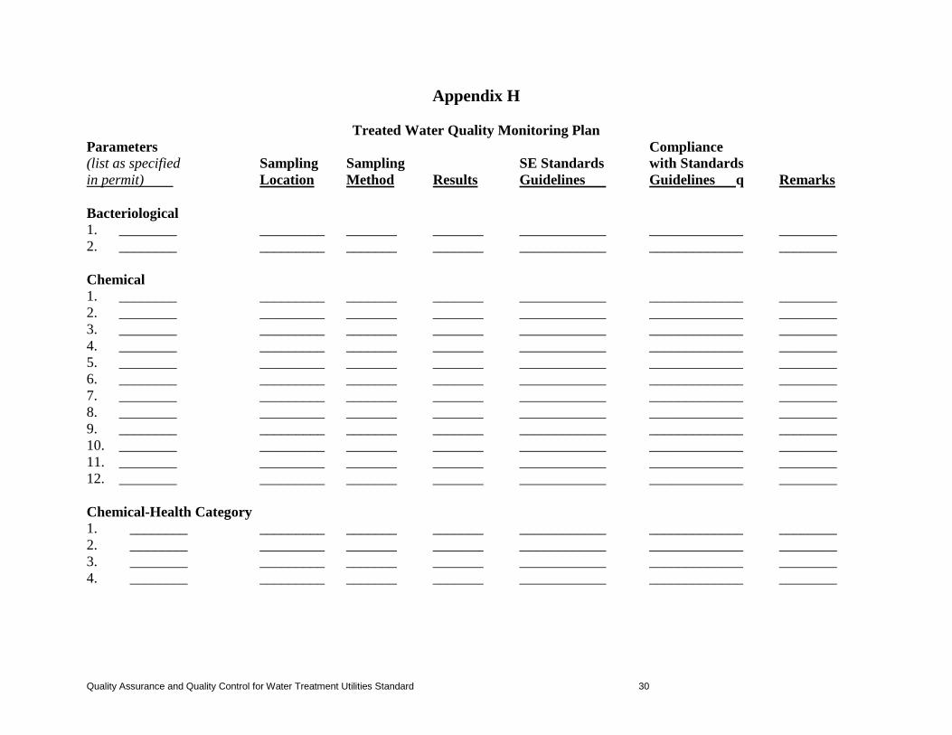
Appendix H
Treated Water Quality Monitoring Plan Parameters Compliance (list as specified Sampling Sampling SE Standards with Standards in permit) Location Method Results Guidelines Guidelines q Remarks Bacteriological 1. ________ _________ _______ _______ ____________ _____________ ________ 2. ________ _________ _______ _______ ____________ _____________ ________
Chemical 1. ________ _________ _______ _______ ____________ _____________ ________ 2. ________ _________ _______ _______ ____________ _____________ ________ 3. ________ _________ _______ _______ ____________ _____________ ________ 4. ________ _________ _______ _______ ____________ _____________ ________ 5. ________ _________ _______ _______ ____________ _____________ ________ 6. ________ _________ _______ _______ ____________ _____________ ________ 7. ________ _________ _______ _______ ____________ _____________ ________ 8. ________ _________ _______ _______ ____________ _____________ ________ 9. ________ _________ _______ _______ ____________ _____________ ________ 10. ________ _________ _______ _______ ____________ _____________ ________ 11. ________ _________ _______ _______ ____________ _____________ ________ 12. ________ _________ _______ _______ ____________ _____________ ________
Chemical-Health Category 1. ________ _________ _______ _______ ____________ _____________ ________ 2. ________ _________ _______ _______ ____________ _____________ ________ 3. ________ _________ _______ _______ ____________ _____________ ________ 4. ________ _________ _______ _______ ____________ _____________ ________
Quality Assurance and Quality Control for Water Treatment Utilities Standard 30

Physical 1. pH _________ _______ _______ ____________ _____________ ________ 2. Temperature _________ _______ _______ ____________ _____________ ________ 3. ____________ _________ _______ _______ ____________ _____________ ________ 4. ____________ _________ _______ _______ ____________ _____________ ________ 5. ____________ _________ _______ _______ ____________ _____________ ________ Other 1. Turbidity _________ _______ _______ ____________ _____________ ________ 2. Residual _________ _______ _______ ____________ _____________ ________ 3. Disinfectant _________ _______ _______ ____________ _____________ ________ 4. Concentration _________ _______ _______ ____________ _____________ ________
Quality Assurance and Quality Control for Water Treatment Utilities Standard 31
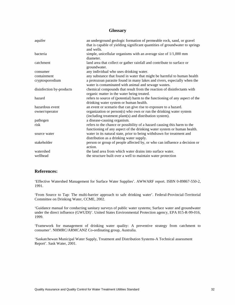
Glossary aquifer an underground geologic formation of permeable rock, sand, or gravel
that is capable of yielding significant quantities of groundwater to springs and wells.
bacteria simple, unicellular organisms with an average size of 1/1,000 mm diameter.
catchment land area that collect or gather rainfall and contribute to surface or groundwater.
consumer any individual who uses drinking water. containment any substance that found in water that might be harmful to human health cryptosporodium a protozoan parasite found in many lakes and rivers, especially when the
water is contaminated with animal and sewage wastes. disinfection by-products chemical compounds that result from the reaction of disinfectants with
organic matter in the water being treated. hazard refers to source of (potential) harm to the functioning of any aspect of the
drinking water system or human health. hazardous event an event or scenario that can give rise to exposure to a hazard. owner/operator organization or person(s) who own or run the drinking water system
(including treatment plant(s) and distribution system). pathogen a disease-causing organism. risk refers to the chance or possibility of a hazard causing this harm to the
functioning of any aspect of the drinking water system or human health. source water water in its natural state, prior to being withdrawn for treatment and
distribution as a drinking water supply. stakeholder person or group of people affected by, or who can influence a decision or
action. watershed the land area from which water drains into surface water. wellhead the structure built over a well to maintain water protection References: ‘Effective Watershed Management for Surface Water Supplies’. AWWARF report. ISBN 0-89867-550-2, 1991. ‘From Source to Tap: The multi-barrier approach to safe drinking water’. Federal-Provincial-Territorial Committee on Drinking Water, CCME, 2002. ‘Guidance manual for conducting sanitary surveys of public water systems; Surface water and groundwater under the direct influence (GWUDI)’. United States Environmental Protection agency, EPA 815-R-99-016, 1999. ‘Framework for management of drinking water quality: A preventive strategy from catchment to consumer’. NHMRC/ARMCANZ Co-ordinating group, Australia. ‘Saskatchewan Municipal Water Supply, Treatment and Distribution Systems-A Technical assessment Report’. Sask Water, 2001.
Quality Assurance and Quality Control for Water Treatment Utilities Standard 32

![[List University Name] Quality Assurance Program ... Assurance Foms/University... · [List University Name] Quality Assurance Program Description Document ... Quality Assurance Program](https://static.fdocuments.us/doc/165x107/5ab8c3d37f8b9aa6018d08ac/list-university-name-quality-assurance-program-assurance-fomsuniversitylist.jpg)