Qualitative Studies with Microwaves - University Of Illinois · Radar (up to 110GHz) Motion...
35
Qualitative Studies with Microwaves Physics 401, Spring 2017 Eugene V. Colla
Transcript of Qualitative Studies with Microwaves - University Of Illinois · Radar (up to 110GHz) Motion...
Qualitative Studies
with Microwaves
Physics 401, Spring 2017Eugene V. Colla
3/27/2017 Physics 401 2
This is two weeks Lab
The main goals of the Lab:
Refreshing the memory about the
electromagnetic waves propagation
Microwaves. Generating and detecting of
the microwaves
Microwaves optic experiments

3/27/2017 Physics 401 33/27/2017
The microwave range includes ultra-high frequency (UHF) (0.3–3 GHz),
super high frequency (SHF) (3–30 GHz), and extremely high frequency
(EHF) (30–300 GHz) signals.
Microwave
Electromagnetic spectrum* *by courtesy Wikipedia

3/27/2017 4
*by courtesy Wikipedia
Microwave oven (2.45GHz)Satellite TV (4-18GHz)
Communication
(0.8-2.69GHz)
Radar
(up to 110GHz)
Motion detector (10.4GHz)
Weather radar (8-12Ghz)
Physics 401
GPS 1.17-1.575 GHz

3/27/2017 Physics 401 53/27/2017
James Clerk Maxwell
(1831–1879)
D
0B D
H Jt
BE
t
If = 0 and J = 0 and taking in account that
(1) and (4) can be rewritten as
(1) (3)
(4)(2)
0y zx
E EED
x y z
DH
t
D E
B H
3/27/2017 Physics 401 63/27/2017
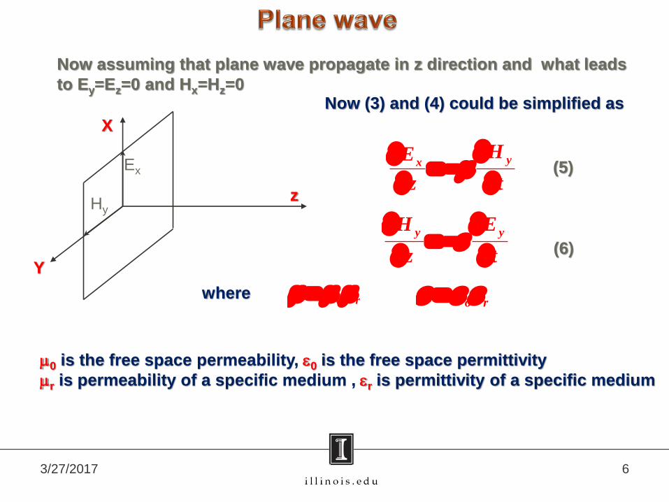
Now assuming that plane wave propagate in z direction and what leads
to Ey=Ez=0 and Hx=Hz=0
Y
X
z
Ex
Hy
Now (3) and (4) could be simplified as
y yH E
z t
yxHE
z t
whereo r
o r
0 is the free space permeability, 0 is the free space permittivity
r is permeability of a specific medium , r is permittivity of a specific medium
(5)
(6)

3/27/2017 Physics 401 73/27/2017
Combining (5) and (6) (see Lab write-up for more details) we finally can
get the equations of propagation of the plane wave:
Y
X
z
Ex
Hy
2 2
2 2 2
1x xE E
z v t
2 2
2 2 2
1y yH H
z v t
where1
v
(7) (8)
Solution for (7) and (8) can found as
0cos( )
x xE E t kx
0cos( - )
y yH H t kx
y xH E
or
x yE ZH
where Z
known as characteristic impedance of medium
k is wave vector and is defined as2
k
or k
v
0
0
377fs
Z ohms
For free space (r=1 and r=1)

3/27/2017 Physics 401 83/27/2017
Y
X
z
Ex
Hy
1v
0cos( )
x xE E t kx
0cos( - )
y yH H t kx
y xH E
x yE ZHZ
2k
or k
v
0
0
377fs
Z ohms
For free space (r=1 and r=1)

3/27/2017 Physics 401 93/27/2017
Vacuum tubes: klystron, magnetron, traveling wave tube
Solid state devices: FET, tunneling diodes, Gunn diodes
Tunable frequency
from 9 to 10GHz;
maximum output
power 20mW
426A
Microwave oven magnetron;
typical power 0.7-1.5kW
Heated cathode as
electron source
3/27/2017 Physics 401 103/27/2017
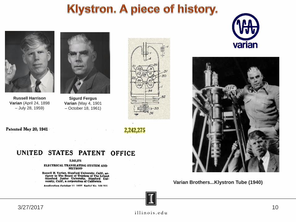
Russell Harrison
Varian (April 24, 1898
– July 28, 1959)
Sigurd Fergus
Varian (May 4, 1901
– October 18, 1961)
Varian Brothers...Klystron Tube (1940)

3/27/2017 Physics 401 113/27/2017
Generating of the microwaves. Klystron.
Single transit klystron Reflection klystron
Advantages: well defined
frequencies,
high power
output
High power klystron
used in Canberra Deep
Space Communications
Complex (courtesy of
Wikipedia)

3/27/2017 123/27/2017
2K25 Klystron
GENERAL CHARACTERISTICS
Frequency Range ·······················8,500 to 9,660 Mc
Cathode Oxide-coated, indirectly heated
Heater Voltage····································6.3Volts
Heater Current···························0.44 Amperes
3/27/2017 Physics 401 133/27/2017
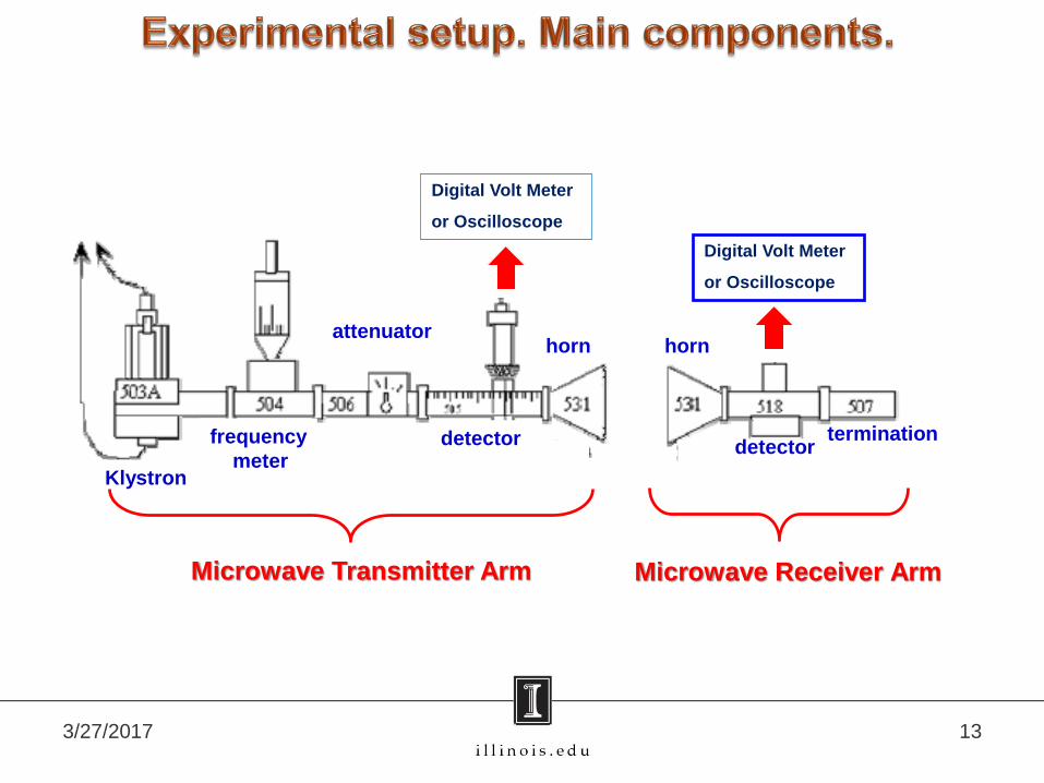
Klystron
frequency
meter
attenuator
detector
horn horn
detectortermination
Microwave Transmitter Arm Microwave Receiver Arm
Digital Volt Meter
or Oscilloscope
Digital Volt Meter
or Oscilloscope

3/27/2017 Physics 401 143/27/2017
Experimental setup. Main components.
Attenuator
KlystronFrequency meter detector
3/27/2017 Physics 401 153/27/2017
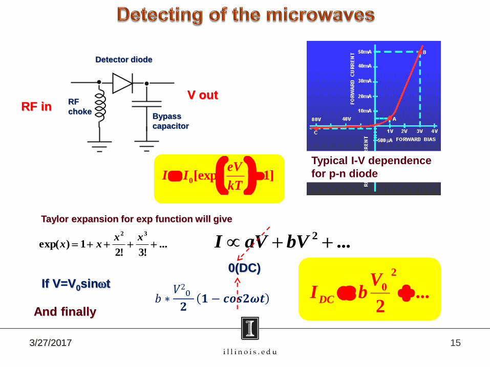
0[exp 1]
eVI I
kT
Typical I-V dependence
for p-n diode
Taylor expansion for exp function will give:
...!3!2
1)exp(32
xx
xx
And finally
...2 bVaVI
RF
choke
Detector diode
Bypass
capacitor
RF inV out
If V=V0sint
𝑏 ∗𝑉2
0
𝟐𝟏 − 𝒄𝒐𝒔𝟐𝝎𝒕
2
0 ...2
DC
VI b
0(DC)
3/27/2017 Physics 401 163/27/2017
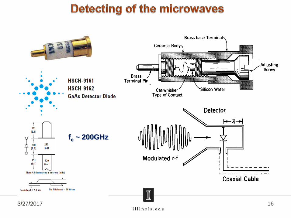
fc ~ 200GHz

3/27/2017 Physics 401 173/27/2017
The Nobel Prize in Physics 1907
Albert Abraham Michelson
(1852 - 1931)
Mirror A
Mirror B
Receiver
Transmitter
Beam splitter
2 BR L kL
LB
LR
Condition for constructive interference
LR, LB optical paths (OP) for
“red” and “blue” rays
OP = n*LG
n – refraction index;
LG – geometrical length

3/27/2017 Physics 401 183/27/2017
Physics 403 Lab Michelson interferometer setup
3/27/2017 Physics 401 193/27/2017
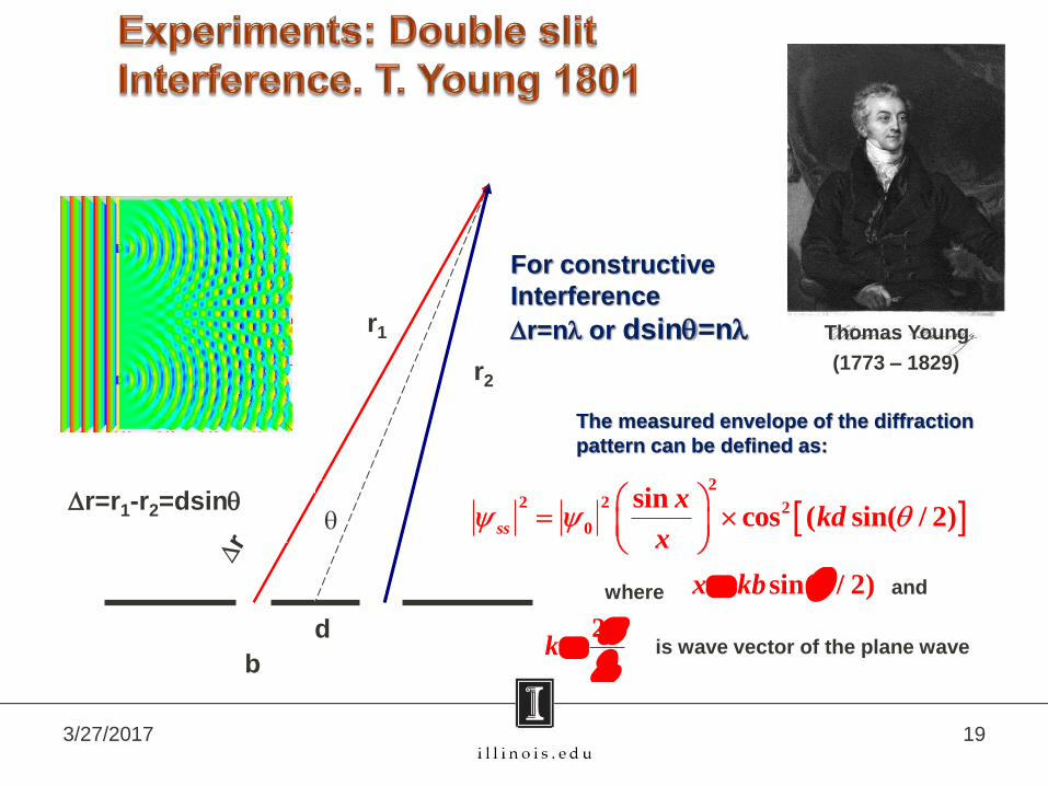
Thomas Young
(1773 – 1829)
r1
r2
For constructive
Interference
Dr=n or dsinq=n
d
qDr=r1-r2=dsinq
b
2
2 2 2
0
sincos ( sin( / 2)
ss
xkd
x q
The measured envelope of the diffraction
pattern can be defined as:
where sin( / 2)x kb q and
2k
is wave vector of the plane wave
3/27/2017 Physics 401 203/27/2017
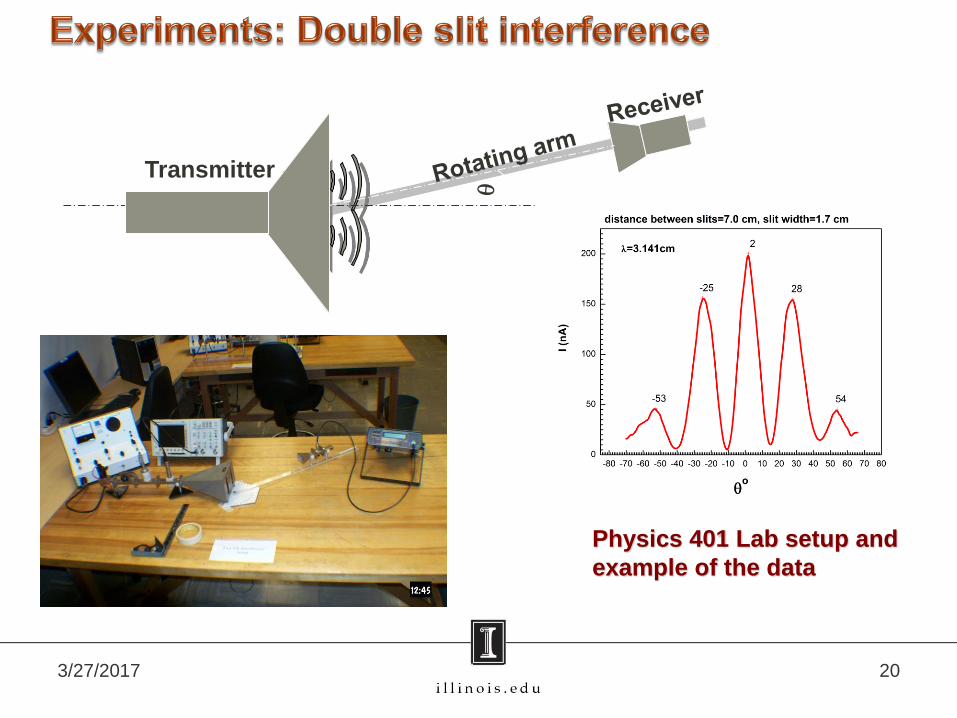
Transmitter
Physics 401 Lab setup and
example of the data

3/27/2017 Physics 401 213/27/2017
2
2 2 2
0
sincos ( sin( / 2)
ss
xkd
x q
sin( / 2)x kb q
Model Two_slit (User)
Equation y=I0*(sin(K1*sin(pi*x/360+f))/(K1*sin(pi*x/360+f)))
^2 *(cos(K2*sin(pi*x/360+f)))^2+I00
Reduced Chi-Sqr 94.62111
Adj. R-Square 0.96659 Value Standard Error
I0 190.6014 3.042882
K1 4.384042 0.074754
K2 13.51332 0.052244
f -0.01525 7.19E-04
I00 9.572049 1.440409
-100 -50 0 50 1000
100
200
I (n
A)
qo
=3.141cm
Here in fitting expression:
𝑰𝟎 = 𝝍𝟎𝟐;
𝑲𝟏 = 𝒌𝒃;𝑲𝟐 = 𝒌𝒅
𝒚 = 𝑰𝟎 ∙𝐬𝐢𝐧(𝑲𝟏 𝐬𝐢𝐧
𝝅𝒙
𝟑𝟔𝟎+𝒇
𝑲𝟏 𝒔𝒊𝒏𝝅𝒙
𝟑𝟔𝟎+𝒇
2𝐜𝐨𝐬𝟐 𝑲𝟐𝐬𝐢𝐧𝝅𝒙
𝟑𝟔𝟎+ 𝒇 +I00
Fitting equation

3/27/2017 Physics 401 223/27/2017
h
d1 d2
Mirror
Transmitter Receiver
2 2 2 2( 1 21 )2h d h d dS d D
Difference of the wave paths of
“red” and “blue” rays is:
For constructive interference
DS=n
Lab setup picture
Humphry Lloyd
1802-1881

3/27/2017 Physics 401 233/27/2017
q1
q2
n1
n2
Claudius Ptolemaeus
after AD 83–c.168)
n1sinq1=n2sinq2
n1>n2
Equation for critical angle:
n1sinqc=n2sin90o
qc=sin-1(n2/n1)
Willebrord Snellius
1580-1626
Snell’s law

3/27/2017 Physics 401 243/27/2017
Transmitter
Lucite prism
n1(lucite)
n2(air)
0 20 40 60 80 1000.0
0.5
1.0
1.5
Sig
nal
in
ten
sity
(
A)
Angle q0
Experimental setup and the example of the data

3/27/2017 Physics 401 253/27/2017
Transmitter Receiver
Polarizer
Metallic gridq
Tra
ns
mit
ter
E=E0cosq
I∞E2
I=I0cos2q
Etienne-Louis Malus
1775 – 1812
Malus law

3/27/2017 Physics 401 263/27/2017
I=I0cos2q
Transmitter Rotatable receiver
Polarizer
Experimental data

3/27/2017 Physics 401 273/27/2017
Sir William Henry Bragg
1862-1942
William Lawrence Bragg
1890-1971
The Nobel Prize in Physics 1915"for their services in the analysis of
crystal structure by means of X-rays"
Interference of the EM waves
reflected from the crystalline layers

3/27/2017 Physics 401 283/27/2017
(100) (110) (210)
Different orientations of the crystal

3/27/2017 Physics 401 293/27/2017
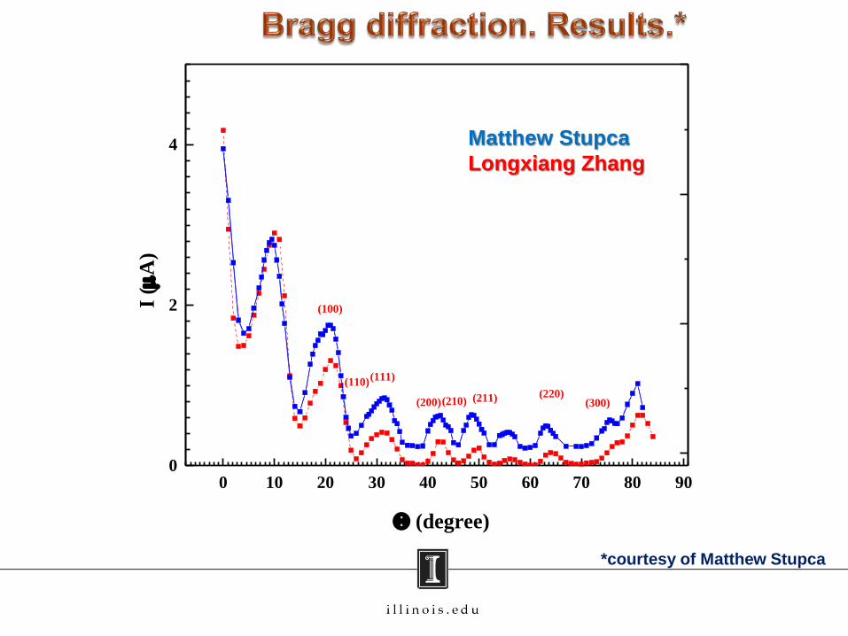
n=2dsinq <2d
In our experiment ~3cm;
For cubic symmetry the
angles of Bragg peaks
can be calculated from:
2 2
2 2 2
sin
2d h k l
q
where h,k,l are the Miller Indices.
For crystal with d=5cm and =3cm
the 3 first Bragg peaks for (100)
orientation can be found at
angles: ~17.5o; 36.9o and 64.2oExperimental setup
crystal

3/27/2017 Physics 401 30
q
q
3/27/2017 Physics 401 31
*courtesy of Matthew Stupca
0 10 20 30 40 50 60 70 80 900
2
4
(100)
(110)(111)
(200)(210) (211) (220)(300)
I (
A)
(degree)
Matthew Stupca
Longxiang Zhang
3/27/2017 Physics 401 32
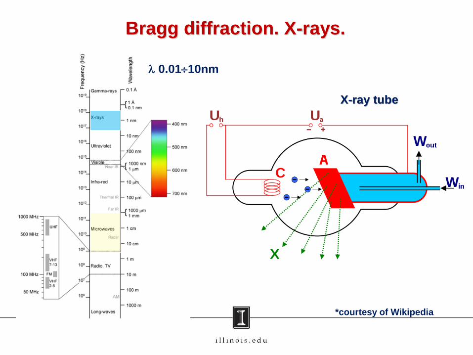
Bragg diffraction. X-rays.
*courtesy of Wikipedia
X-ray tube
0.0110nm

3/27/2017 Physics 401 33
Bragg diffraction. X-rays.
*courtesy of Matthew Stupca
Target Kβ₁ Kβ₂ Kα₁ Kα₂
Fe 0.17566 0.17442 0.193604 0.193998
Co 0.162079 0.160891 0.178897 0.179285
Ni 0.15001 0.14886 0.165791 0.166175
Cu 0.139222 0.138109 0.154056 0.154439
Zr 0.70173 0.68993 0.78593 0.79015
Mo 0.63229 0.62099 0.70930 0.71359
David R. Lide, ed. (1994). CRC Handbook
of Chemistry and Physics 75th edition.
CRC Press. pp. 10–227
X-ray K-series spectral line wavelengths (nm) for some common target materials

3/27/2017 Physics 401 34
Bragg diffraction. X-rays.
*courtesy of Matthew Stupca

Comments and suggestions
1. Klystron is very hot and the high voltage (~300V) is applied
to repeller.
2. You have to do 6 (!) experiment in one Lab session – take
care about time management. The most time consuming
experiment is the “Bragg diffraction”.
3. Do not put on the tables any extra stuff – this will cause
extra reflections of microwaves and could result in
smearing of the data.
4. This is two weeks experiment but the equipment for the
week 2 will be different. Please finish all week 1
measurements until the end of this week
Good luck !
3/27/2017 Physics 401 35