Quadrotor for Indoor Surveillance and Reconnaissance Conference... · Quadrotor for Indoor...
29
Quadrotor for Indoor Surveillance and Reconnaissance Steven Viska, Scott Kline, Callie Chen, Giuseppe Tonini, Harsh Shah Department of Aerospace Engineering Cal Poly Pomona AIAA Research Conference
-
Upload
phamnguyet -
Category
Documents
-
view
222 -
download
0
Transcript of Quadrotor for Indoor Surveillance and Reconnaissance Conference... · Quadrotor for Indoor...

Quadrotor for Indoor
Surveillance and
Reconnaissance
Steven Viska, Scott Kline, Callie Chen, Giuseppe Tonini, Harsh Shah
Department of Aerospace Engineering
Cal Poly Pomona
AIAA Research Conference
Overview
• Unmanned Aerial Vehicles (UAVs)
• Motivations
• Research Objectives
• Simultaneous Localization and Mapping
• Hardware
• Software
• Obstacle Avoidance
• Autonomous Flight
• Conclusion
• Future Work
2

Unmanned Aerial Vehicles • Unmanned Aerial Vehicle
– Remotely piloted by
human or autonomous
(using autopilot)
• Replace manned operations
to reduce human risk, cost,
and expand capabilities
• Used for: surveillance, target
strike, search and rescue
missions, precision
agriculture, etc.
3

Motivations
• Autonomous navigation in GPS denied indoor
environments
• Aerial reconnaissance for assessment of
indoor environments
• Investigate unknown environments
• Evaluate hazardous or inaccessible
environments
• Minimize human risk
• Promote usability of indoor UAVs
4

Research Objectives
• Implementation of Simultaneous Localization and Mapping (SLAM) for navigation in indoor environments
• Develop a quadrotor capable of supporting the system.
• Minimal size and weight
• Payload capacity and integration
• 3D imaging
• Real-time mapping using a 3D Imaging Camera
• Design a portable power plant
• Wireless capabilities
• Data acquisition from 3D Imaging Camera
5

SLAM
• “Simultaneous localization and mapping”
• Use of 3D Imaging Camera sensors for 3D mapping
- Infrared (IR) projector
- RGB camera
- IR monochrome camera
• Use of FARO Scenect™ software for 3D image
integration
6
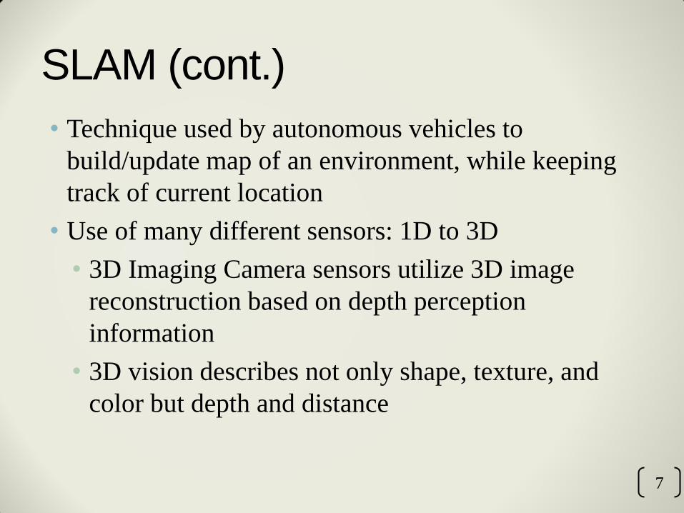
SLAM (cont.)
• Technique used by autonomous vehicles to
build/update map of an environment, while keeping
track of current location
• Use of many different sensors: 1D to 3D
• 3D Imaging Camera sensors utilize 3D image
reconstruction based on depth perception
information
• 3D vision describes not only shape, texture, and
color but depth and distance
7

3D Imaging Cameras • Microsoft Kinect and Asus Xtion Live Pro sensors
used for 3D image reconstruction:
• Infrared (IR) projector
• RGB camera
• IR monochrome camera
8

Camera Comparison
9
Asus Xtion Live Pro Microsoft Kinect
Price ≈$150 ≈$150
Power Consumption <2.5 W 12 W
Distance of use 0.8 m < x < 3.5 m 0.8 m < x < 4 m
Field of View 58° H; 45° V; 70° D 57.5° H; 43.5° V
Depth Image Size VGA (640 x 480) 30 fps; QVGA (320 x 240) 60 fps
VGA (640 x 480) 30 fps
Resolution SXVGA (1280*1024) SXVGA (1280*960)
Software Open NI SDK bundled Kinect for Windows SDK
Dimensions 18 x 3.5 x 5 cm 28 x 8 x 8 cm

3D Mapping Process • Signals are emitted from the IR projector
• Reflected infrared signals are retrieved on the IR
monochrome camera
• 3D depth map is generated
• Chromatic and 3D depth images can be obtained
simultaneously with texture from the RGB camera
• Camera provides automatic calibration based on
physical environment
• Accommodates for the presence of obstacles
10

Architecture for 3D Mapping
11
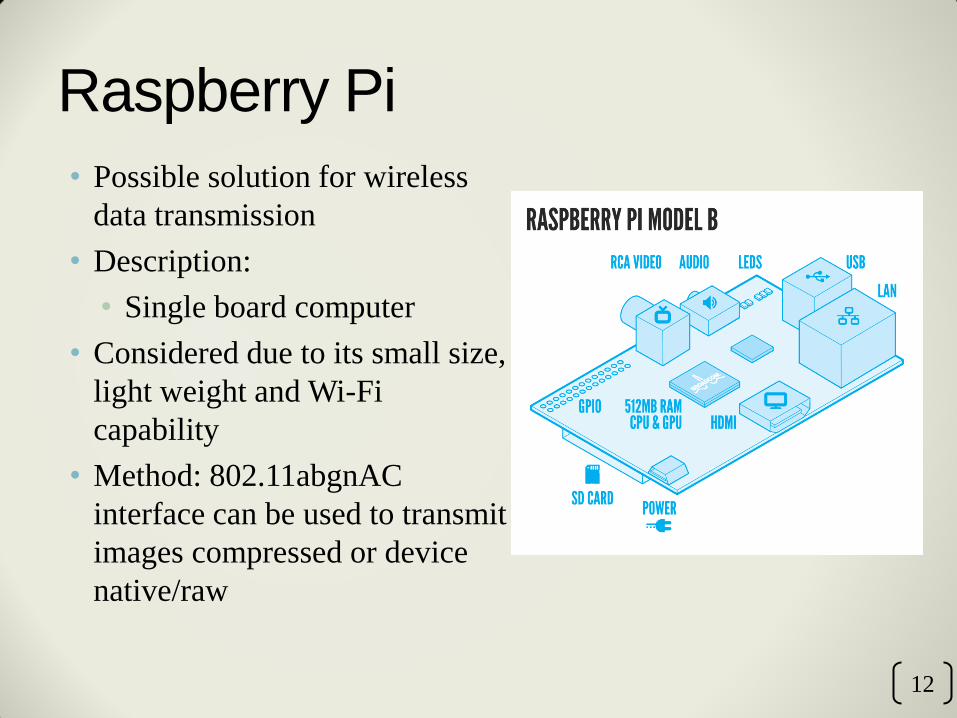
Raspberry Pi
• Possible solution for wireless
data transmission
• Description:
• Single board computer
• Considered due to its small size,
light weight and Wi-Fi
capability
• Method: 802.11abgnAC
interface can be used to transmit
images compressed or device
native/raw
12

Camera Hardware Architecture
13
3D
Imaging
Camera
Raspberry Pi
Model B
Wi-Fi
Dongle
Power Supply
Receiver
Ground
Station
USB Connection
USB
Connection
Micro USB
Connection
Wireless
Signal
Black – Signal
Red – Power

Quadrotor Vehicle
14
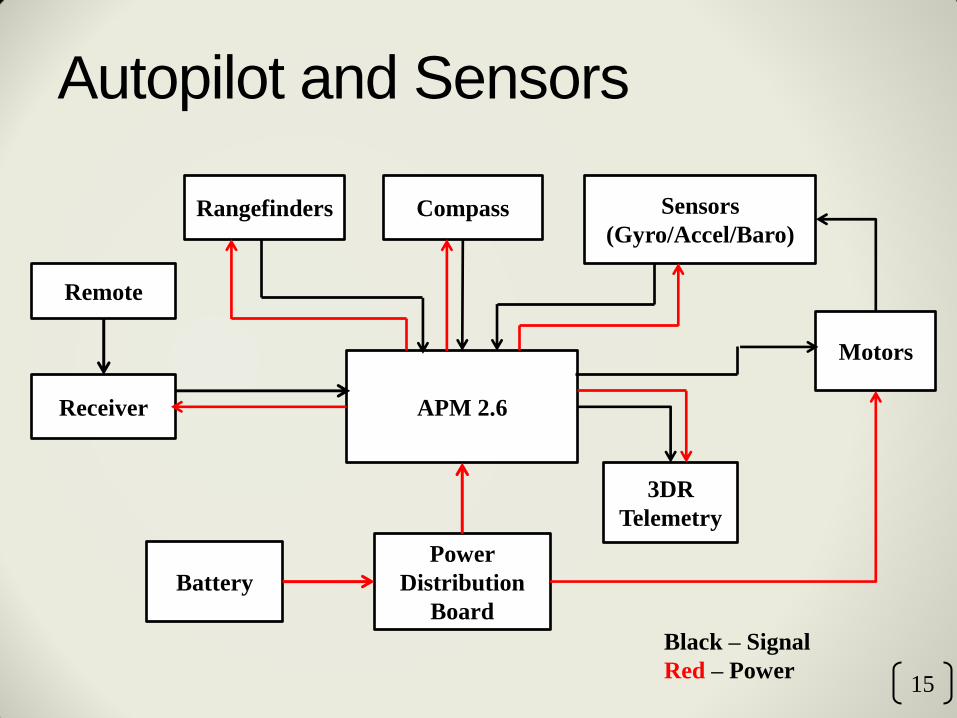
Autopilot and Sensors
Remote
Receiver APM 2.6
Motors
Sensors
(Gyro/Accel/Baro) Rangefinders
Battery
Power
Distribution
Board
15
Compass
3DR
Telemetry
Black – Signal
Red – Power

Ultrasonic Range Finder
• LV-MaxSonar EZ0™
• Range: 6 in – 254 in (6.45 m)
• 2.5V to 5.5V with 2mA current draw
• Readings can occur every 50ms (20 Hz rate)
• Serial, Analog, and Pulse width
16
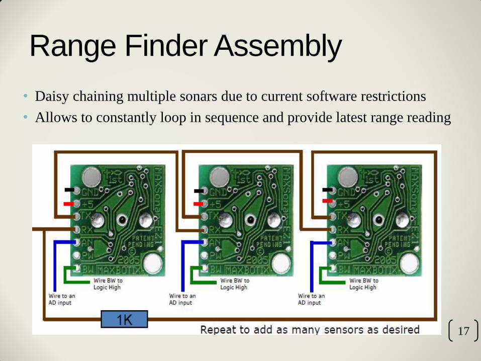
Range Finder Assembly
• Daisy chaining multiple sonars due to current software restrictions
• Allows to constantly loop in sequence and provide latest range reading
17

Overall System Architecture
18
APM 2.6
Sensors
(Gyro/Accel/
Barro) Rangefinders
Ground Station 1
Human
Pilot
Radio Receiver
3-D Imaging
Camera
Radio
Flight
&
Sensor
Data
Image Data Receiver
3DR
Telemetry
Raspberry Pi
Ground Station 2
Wi-Fi
Dongle
Receiver
Wireless
Signal
Wireless
Signal
Compass

Flight Control Software
• Runs on ArduCopter V3.1.2
Quad Configuration
• Works in conjunction with
APM Mission Planner
-Simple configuration and
calibration
-Displays vehicle status
-Displays and monitors
various sensor data
19

Software (cont.)
20
• Vehicle Status

SCENECT
• The SCENE software family is a comprehensive 3D point
cloud processing and managing software for users
• SCENECT by Faro allows the use of 3D Imaging Camera
sensor to capture objects and environments in 3D in real-time
• Allows the users to view, process and analyze recordings
• Can export to different formats for use in third party
applications, like CAD programs
21
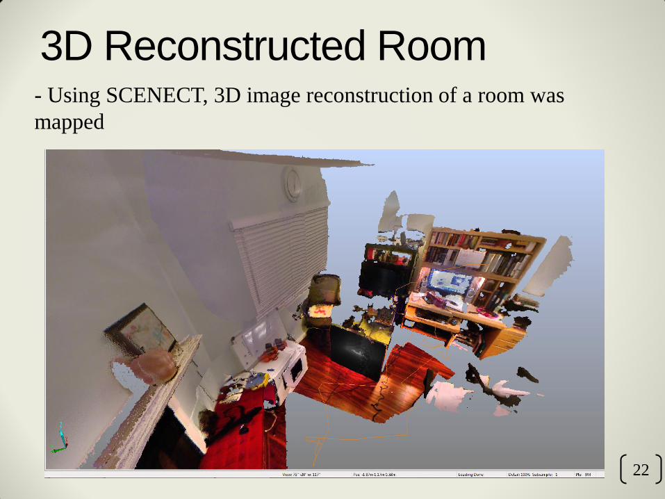
3D Reconstructed Room - Using SCENECT, 3D image reconstruction of a room was
mapped
22
Obstacle Avoidance
• Use of rangefinder sensors to detect obstructions within the
vehicle’s path.
• Reflected signals from the rangefinder discovers the
position and distance
• Six rangefinders will be implemented within the system
• Aligned within half angles of each other to retrieve a clear
resolution of an obstacle
23

Obstacle Avoidance (cont.)
24

Autonomous Flight
• Can be used in any
environment
• Uses barometer, magnetometer,
gyroscope, accelerometer, and
range finder to follow the
assigned path
25

Conclusion
• Obstacle avoidance allows for the safe navigation of
autonomous UAV systems in various environments
• Implementation of SLAM into UAV systems provides
ground work for future applications.
• Mapping of unknown environments
• Creating virtual models of large regions or objects
26

Future Work
• Refinement of Obstacle Avoidance system
• Weight reduction of overall system
• Improvement of overall flight endurance
27

Acknowledgements
• Aerospace Engineering
• Dr. Subodh Bhandari
• Hovig V. Yaralian
28

Questions?
29