Quadrilateral Mesh Generation using Templates -...
20
Quadrilateral Mesh Generation using Templates Antonio Carlos de O. Miranda [email protected] Gilberto Gomes [email protected] Department of Civil and Environmental Engineering, University of Bras´ ılia SG-12 Building, Darcy Ribeiro Campus, DF, 70.910-900, Brazil Luiz Fernando Martha [email protected] Department of Civil Engineering, Pontifical Catholic University of Rio de Janeiro Rua Marquˆ es de S˜ ao Vicente 225, G´ avea, Rio de Janeiro, RJ, 22453-900, Brazil Abstract. This paper describes a quadrilateral mesh generation algorithm ideally suited for tran- sition subdomain meshes in the context of any domain decomposition meshing strategy. The algo- rithm is based on an automatic hierarchical region decomposition in which, in the last level, it is possible to generate quadrilateral elements with a conventional mapping strategy. In two dimen- sions, a subdomain is usually a triangle or a rectangle. In this algorithm, a subdomain with two boundary curves may also be allowed. Templates impose restrictions on the number of boundary curve segments of a subdomain to be meshed. The proposed hierarchical template scheme elimi- nates these restrictions, requiring only an even number of boundary segments. Other algorithms in the literature present similar characteristics. However, the implementation of the hierarchical decomposition and its templates presented here is quite simple compared to other approaches. Six high-level templates are considered for a subdomain, depending on the number of boundary curves and the number of segments on each curve. Several examples demonstrate that this simple idea may result in structured meshes of surprisingly good quality. We also show the possibility of obtaining different meshes for a subdomain with fixed boundary discretization by changing the corners between curves. Keywords: template-based mesh, structured quadrilateral mesh, domain decomposition, mapping, transition mesh CILAMCE 2013 Proceedings of the XXXIV Iberian Latin-American Congress on Computational Methods in Engineering Z.J.G.N Del Prado (Editor), ABMEC, Pirenpolis, GO, Brazil, November 10-13, 2013
Transcript of Quadrilateral Mesh Generation using Templates -...

Quadrilateral Mesh Generation using Templates
Antonio Carlos de O. Miranda
Gilberto Gomes
Department of Civil and Environmental Engineering, University of Brasılia
SG-12 Building, Darcy Ribeiro Campus, DF, 70.910-900, Brazil
Luiz Fernando Martha
Department of Civil Engineering, Pontifical Catholic University of Rio de Janeiro
Rua Marques de Sao Vicente 225, Gavea, Rio de Janeiro, RJ, 22453-900, Brazil
Abstract. This paper describes a quadrilateral mesh generation algorithm ideally suited for tran-sition subdomain meshes in the context of any domain decomposition meshing strategy. The algo-rithm is based on an automatic hierarchical region decomposition in which, in the last level, it ispossible to generate quadrilateral elements with a conventional mapping strategy. In two dimen-sions, a subdomain is usually a triangle or a rectangle. In this algorithm, a subdomain with twoboundary curves may also be allowed. Templates impose restrictions on the number of boundarycurve segments of a subdomain to be meshed. The proposed hierarchical template scheme elimi-nates these restrictions, requiring only an even number of boundary segments. Other algorithmsin the literature present similar characteristics. However, the implementation of the hierarchicaldecomposition and its templates presented here is quite simple compared to other approaches.Six high-level templates are considered for a subdomain, depending on the number of boundarycurves and the number of segments on each curve. Several examples demonstrate that this simpleidea may result in structured meshes of surprisingly good quality. We also show the possibilityof obtaining different meshes for a subdomain with fixed boundary discretization by changing thecorners between curves.
Keywords: template-based mesh, structured quadrilateral mesh, domain decomposition, mapping,transition mesh
CILAMCE 2013Proceedings of the XXXIV Iberian Latin-American Congress on Computational Methods in Engineering
Z.J.G.N Del Prado (Editor), ABMEC, Pirenpolis, GO, Brazil, November 10-13, 2013
Quadrilateral Mesh Generation using Templates
1 Introduction
This paper describes a novel hierarchical template-based meshing scheme for generating good-quality quadrilateral meshes. This approach is ideally suited for transition subdomain meshes inthe context of structured 2D or surface meshing strategies, such as mapping, submapping, sweep-ing, medial axis, auto-decomposition or user-assisted decomposition. One of the main draw-backs of these meshing schemes is the constraint on the number of subdomain boundary curvesegments. For quadrilateral subdomains, the number of segments on opposite boundary curvesmust be equal, and, for triangular subdomains, the three boundary curves must have equal num-ber of segments. In this environment, it is difficult to implement local mesh refinement with-out using non-structured hybrid subdomain meshes because any change in the number of seg-ments of a boundary curve forces the propagation of this modification to opposite subdomaincurves. The proposed hierarchical template-based meshing scheme produces quad-mapping transi-tion meshes without any constraint on the number of boundary segments. The only requirement isthat the total number of segments must be even, which is a general rule for any quadrilateral mesh[Cook and Oakes, 1982, Mitchell, 2000].
In the context of quadrilateral mesh generation, template is a pattern that describes how asingle polygon can be decomposed into quadrilaterals. In two dimensions or in surface mesh-ing, a single polygon is usually a triangle or a rectangle. Many finite element meshing algo-rithms use templates to some degree. For example, mapping techniques may be considered assimple templates. Initially, classical structured mapping strategies [Gordon and Hall, 1973] wereproposed, defining generalized curvilinear coordinate systems for closed, bounded and simplyconnected domains on the plane or in 3D surfaces. A similar approach was proposed in an-other work [Cook, 1974] for generated hexahedral meshes using body-oriented coordinates de-fined by three-dimensional regions bounded by six surfaces. In both works, transfinite mappingtechniques were established for curvilinear coordinate systems in arbitrary domains to approx-imate complex surfaces and volumes. Haber et al. [Haber et al., 1981] and Haber and Abel[Haber and Abel, 1982] used transfinite mappings based on discrete boundary curves, and appliedthese techniques to two-dimensional and three-dimensional surface preprocessing programs. Thisdiscrete form of the mapping allows representing boundary geometries generically. The basic ideaof these works is to use triangular and quadrilateral template meshes in a parametric space andmap them to Cartesian space. Similar ideas were developed to generate three-dimensional meshes[Cook and Oakes, 1982, Perucchio et al., 1982]. It is interesting to observe that, in 1982, Cookand Oakes [Cook and Oakes, 1982] presented examples of quadrilateral mesh grading algorithmsfor gradual or rapid element density transitions, but the algorithms were not formalized. Similartechniques were cited by Thompson [Thompson et al., 1999].
Another meshing technique that employs templates is recursive domain subdivision usingquadtree [Samet, 1984]. Yerry and Shephard [Yerry and Shephard, 1983] pioneered this technique,proposing templates to generate triangular and quadrilateral elements. Other works have been pub-lished following similar ideas with some improvements and modifications [Baehmann et al., 1987,Yiu et al., 1996, Smith and Johnston, 1996, Liang et al., 2010]. In general, this mesh generationprocess is implemented in three stages. Initially, the domain’s interior is filled with a quadtree that is
CILAMCE 2013Proceedings of the XXXIV Iberian Latin-American Congress on Computational Methods in EngineeringZ.J.G.N Del Prado (Editor), ABMEC, Pirenpolis, GO, Brazil, November 10-13, 2013

A.C.O. Miranda and L.F. Martha
recursively and locally refined according to given boundary refinement information. Care is taken toavoid adjacent quadtree cells that have a difference of more than one in tree depth. Then, templatesthat depend on cell adjacency are employed to mesh the interior cells. In a final stage, the regionbetween the interior mesh and the boundary is also meshed using several meshing schemes, whichmight employ other types of templates. A recent work [Liang et al., 2010] describes a templatescheme for meshing all quadrilateral elements with guaranteed quality while preserving featuresof the boundary. Analogous procedures are used for three-dimensional mesh generation using anoctree [Thompson et al., 1999, Yerry and Shephard, 1984, Zhang and Zhao, 2007, Ito et al., 2009].Schneiders et al. [Schneiders et al., 1996] presented original templates to generate hexahedral ele-ments in octree cells, which were improved by Ito et al. [Ito et al., 2009].
There are many other meshing algorithms that use templates. Schneiders [Schneiders, 2000]reviewed the state of the art in quadrilateral and hexahedral mesh generation in 2000 and describedmany techniques that employ templates. Templates are naturally used in association with a domaindecomposition strategy, in which a domain is decomposed into subdomains where a specific tem-plate is chosen to generate quadrilateral elements. For example, Nowottny [Nowottnys, 1997] useda geometry-based optimization for selecting appropriate cuts dividing the domain and presenteda set of meshing templates for triangular and rectangular polygons. In a sense, the hierarchicalmeshing scheme proposed in the present paper is a generalization of the templates presented byNowottny. Muller-Hannemann [Muller-Hannemann, 2000] decomposed a coarse mesh of polygonsin three-dimensional space into quadrilaterals. In these subdomains, mesh is generated with tem-plates that satisfy prescribed local density constraints. Four quadrilateral templates are presentedthat are similar to some present here. Lizier et al. [Lizier M. and L., 2011] proposed a template-based approach for generating quad-only meshes from 2D digital images. The same authors usedthe same technique to generate quad meshes from triangle surfaces [Daniels et al., 2011]. In bothworks, they fill the subdomains with triangular and quadrilateral templates. In addition, many otherapproaches for 3D domain decomposition generate meshes using templates [Staten et al., 2010,Mitchell, 1999, Yamakawa and Shimada, 2001]. A commercial software for finite element analysisalso employs templates for subdomain mesh transition using quadrilateral and hexahedral elements[Ansys, 2013].
The mesh generation algorithm proposed in this work is also devised in the context of a do-main decomposition meshing strategy. As mentioned, in two dimensions, a subdomain is usu-ally a triangle or a rectangle. In this work, a subdomain with two boundary curves may be al-lowed. Templates impose restrictions on the number of boundary curve segments of a subdomainto be meshed. The proposed hierarchical template scheme eliminates these restrictions, requir-ing only an even number of boundary segments. The algorithm introduced by Muller-Hannemann[Muller-Hannemann, 2000] presents the same characteristic. However, our algorithm has a simplerand more direct approach than that algorithm.
Six high-level templates are considered here for a subdomain, depending on the number ofboundary curves and the number of segments on each curve: three templates have four curves, twohave three curves, and one has two curves. A boundary curve is given by a set of segment points(boundary nodes) and may include a group of geometric curves. A transition subdomain may have
CILAMCE 2013Proceedings of the XXXIV Iberian Latin-American Congress on Computational Methods in Engineering
Z.J.G.N Del Prado (Editor), ABMEC, Pirenpolis, GO, Brazil, November 10-13, 2013

Quadrilateral Mesh Generation using Templates
four, three, or even two boundary curves. Based on the input boundary data, the hierarchical schemeselects the target high-level template (classification) and recursively decomposes the subdomaininto regions in which only quadrilateral templates may be adopted. The recursive decompositionresults in subregions that are meshed using the classical quad-mapping scheme. The hierarchicalrecursive depth is three at most.
Although template-based quadrilateral mesh generation has already been studied by other au-thors, as described above, this work presents some contributions, namely:
• an automatic recursive region decomposition in which, in the last level, it is pos-sible to generate quadrilateral elements with a conventional mapping strategy;
• the proposed template with three curves does not impose constraints on the num-ber of subdivisions, such as the ones required by the tri-mapping technique [Mitchell, 2000],for instance;
• a new alternative template for subdomains with three curves for a particular caseof curve subdivision;
• a new template for subdomains with two curves.
One of the main advantages of the proposed scheme is that it generates topologically equivalentmeshes for subdomains with the same number of curves and boundary segments. This characteristicmay be explored in volume sweeping meshing, since the source and target surface meshes aretopologically equivalent. Another advantage is the possibility of obtaining different meshes for asubdomain with fixed boundary discretization by changing the corners between curves, as shownin the examples section. Finally, the implementation of the hierarchical decomposition presentedhere, and its templates, is quite simple when compared to other approaches.
2 Main Concept
Following the ideas of Haber et al. [Haber et al., 1981, Haber and Abel, 1982], the inputdata for the proposed quadrilateral mesh generation scheme on a subdomain is a discrete repre-sentation of boundary curves (polylines). As mentioned, this discrete form allows representingboundary geometries generically. This form of representation is quite simple, and may be im-plemented in any programming language as a vector of real numbers which is a sequential listof boundary points (or nodes) and the number of segments (or edges) in each boundary curve:(x1, y1, z1, x2, y2, z2, ..., xn, yn, zn). As also mentioned, to generate quadrilateral elements the totalnumber of edges on the boundary must be even. A subdomain may be composed of four, three, ortwo boundary curves that do not intersect themselves. The number of boundary curves is indicatedby the number of corner nodes, which are given by a set of indices to the input boundary coordinatevector.
Figure 1 shows the set of templates considered in this work, which are used to decompose aregion in subregions. They consist of two templates with four curves (T1 and T2), two templateswith three curves (T3 and T4), and one template with two curves (T5). The letters A,B,C, andD in Figure 1 correspond to the number of edges in each boundary curve. Note that template
CILAMCE 2013Proceedings of the XXXIV Iberian Latin-American Congress on Computational Methods in EngineeringZ.J.G.N Del Prado (Editor), ABMEC, Pirenpolis, GO, Brazil, November 10-13, 2013

A.C.O. Miranda and L.F. Martha
Figure 1: Templates used to decompose regions and their nomenclature.
Figure 2: Example of hierarchical decomposition of templates to generate quadrilateral elements.
T0 does not decompose the region; it is used only to generate quadrilateral elements through theconventional mapping method in which A = B and C = D.
The prior selection (first level) of one of the templates in Figure 1 depends on number of edgeson each curve. If the number of edges on opposite sides is equal, then template T0 is selected, andquadrilateral elements are generated by the conventional mapping method. If it is not possible touse template T0 in the first level, one of the five other templates is selected. Each of these templatesdecomposes the first level subdomain into regions (second level), and a new template is selected foreach region. This process is repeated recursively for each region until a subregion can be meshedusing template T0. Due to this recursive process, the proposed template-based quadrilateral meshgeneration can be understood as a hierarchical decomposition. The whole scheme was devised insuch a way that the hierarchical recursive depth, i.e. the number of levels, is three at most. Forexample, Figure 2 shows a subdomain composed by three boundary curves. In the first level, tem-plate T3 is selected. In the second level, three different templates are selected for each subregion(T2, T0, and T1). In the third and last level, template T0 is selected for all subregions, which arethe leaves in the hierarchical decomposition.
CILAMCE 2013Proceedings of the XXXIV Iberian Latin-American Congress on Computational Methods in Engineering
Z.J.G.N Del Prado (Editor), ABMEC, Pirenpolis, GO, Brazil, November 10-13, 2013

Quadrilateral Mesh Generation using Templates
A key point in the hierarchical decomposition meshing scheme is the selection of a templateto be used in a region. First, the selection is based on the number of boundary curves, given thenumber of curves in a region and their number of edges (A, B, C, and D). Then, the selectionis based on the number of edges of each curve. The result will be a non-valid selection if thetotal number of subdivision edges is not even (a null value is returned). If the selection results intemplate T0, the corresponding region is meshed (conventional mapping) and the recursive processfor that region stops. If the selected template is other than T0, the region is divided and again othertemplates are selected for each resulting subregion. The process is repeated recursively until T0 isselected for all subregions. To obtain the final subdomain mesh, the meshes of all T0 subregionleaves are merged.
3 Implementation Details
The equations presented by Gordon & Hall [Gordon and Hall, 1973] for transfinite mappingof surface patches with four and three curves are used here to compute the position of any interiorpoint generated by the hierarchical decomposition scheme. Considering that the input to the algo-rithm is a set of edges on the boundary curves, as described in the previous section, the discretetransfinite mapping presented by Haber et al. [Haber et al., 1981, Haber and Abel, 1982] is con-veniently applied in this context. The mapping expressions are reproduced in equation (1) for thebilinear projector and in equation (2) for the trilinear projector. Therefore, in a more general form,the proposed scheme can be applied to 3D surface patches. In this case, a generated internal pointis projected to the closest point on the surface.
F (u, v) = (1− v)ψ1(u) + vψ2(u) + (1− u)ξ1(v) + uξ2(v)
−(1− u)(1− v)F (0, 0)− (1− u)vF (0, 1)−uvF (1, 1)− u(1− v)F (1, 0) (1)
T (u, v, w) =1
2
[(u
1− v
)ξ(v) +
(w
1− v
)η(1− v) +
(v
1− w
)η(w)
+(
u
1− w
)ψ(1− w) +
(w
1− u
)ψ(u)
+(
v
1− u
)ξ(1− u)− wψ(0)− uξ(0)− vη(0)
](2)
A key aspect of the proposed hierarchical decomposition process of a region is defining thenumber of edges that will be used on the boundaries of each subregion. The number of edges isdefined based on the lengths of the boundary curves. These lengths are computed in 3D using thegiven discrete polyline geometric information on each curve. The following paragraphs detail, foreach adopted template, the decomposition process and the computation of the number of edges onthe boundaries of each resulting subregion.
CILAMCE 2013Proceedings of the XXXIV Iberian Latin-American Congress on Computational Methods in EngineeringZ.J.G.N Del Prado (Editor), ABMEC, Pirenpolis, GO, Brazil, November 10-13, 2013

A.C.O. Miranda and L.F. Martha
Figure 3: Decomposition of the proposed templates in parametric and in Cartesian spaces.
CILAMCE 2013Proceedings of the XXXIV Iberian Latin-American Congress on Computational Methods in Engineering
Z.J.G.N Del Prado (Editor), ABMEC, Pirenpolis, GO, Brazil, November 10-13, 2013

Quadrilateral Mesh Generation using Templates
Template T1, shown in Figure 3(a), is applied when the number of edges of a pair of oppositecurves is equal (C = D), and the number of edges of the other pair of opposite curves is different(A 6= B). As required, the values of A and B must satisfy the restriction [(A + B)mod2] = 0.Considering B > A, the number of edges b is given by b = (A− B)/2. Values of u1, u2, v1, v2 inparametric space, see Figure 3(a1), are computed as:
u1 =d1d3, u2 =
d2d3, v1 =
d1d1 + d4
, v2 =d2
d2 + d5(3)
in which d1, d2, d3, d4, and d5 are lengths in Cartesian space, as shown in Figure 3(a2). Theparametric values given by equation (3) result in quadrilateral elements of better shape qualitygenerated in each subregion. All subregions generated by template T1 have the final template T0,with the following distribution of boundary edges:
• Subregion 1, A× b edges;
• Subregion 2, b× C edges;
• Subregion 3, A× C edges;
• Subregion 4, b× C edges.
Template T2, shown in Figure 3(b1), is used when the number of edges of opposite curves isnot equal, that is, A 6= B and C 6= D. However, the evenness property requires the number ofedges to be [(A+B + C +D)mod2] = 0 . In Figure 3(b1), B > A and D > C, and the numberof edges b is obtained from the expression b = Min(A − B,C − D)/2. Values of u1 and v1 inparametric space, see Figure 3(b1), are computed by:
u1 =d1d3, v1 =
d2d4
(4)
in which d1, d2, d3 and d4 are lengths in 3D space, as shown in Figure 3(b2). The subregionsgenerated by template T1 have the following distribution of boundary edges:
• Subregion 1, A× b edges, with final template T0;
• Subregion 2, b× C edges, with final template T0;
• Subregion 3 with two possibilities: (1) If A = (B − b) and C = (D − b), thefinal template is T0; (2) If A 6= (B− b) or C 6= (D− b), the final template is T1,which is decomposed recursively.
Both templates T1 and T2 have been presented by other authors [Nowottnys, 1997, Muller-Hannemann, 2000,Lizier M. and L., 2011, Ansys, 2013]. However, the templates presented here are more flexible be-cause they may be applied recursively. This is one of the main advantages of the proposed meshingscheme, which turns out to be a natural way to apply templates. This may be noticed by comparingthe proposed templates with the ones of a commercial software [Ansys, 2013], for example, whichimposes further restrictions on curve subdivision.
Template T3, as shown in Figure 3(c1), consists in decomposing the region into three subre-gions of four curves. The procedure used here is similar to that used in trimapping [Mitchell, 2000].
CILAMCE 2013Proceedings of the XXXIV Iberian Latin-American Congress on Computational Methods in EngineeringZ.J.G.N Del Prado (Editor), ABMEC, Pirenpolis, GO, Brazil, November 10-13, 2013

A.C.O. Miranda and L.F. Martha
Figure 4: Pseudo-code to obtain the number of edges in template T3.
However, here it is extended to use templates in a hierarchical manner. The problem with trimap-ping is that it presents the following restriction:
A+B > C + 2, B + C > A+ 2, C + A > B + 2. (5)
The numbers of edges a, b, and c, as shown in Figure 3(c1), are achieved as follows:
a = (A+B − C)/2, b = (B + C − A)/2, c = (C + A−B)/2. (6)
The procedure proposed here to template T3 does not necessarily conform to equation (5).When this restriction is not satisfied, an offset correction is applied, resulting in the number ofedges given by equation (6). Figure 4 shows a pseudo-code to this procedure. Given the numberof edges in each boundary curve (A, B, and C) of the original region, the number of edges in eachinternal curve (a, b, c, d, e, f , and g) is obtained. Initially, the values of a, b, and c are calculatedusing equation (6). If the restrictions in equation (5) are not obeyed, one of these calculated valueswill be equal to or smaller than zero, and all values need to be adjusted by an offset correction. Theoffset is a unit subtracted from the lower calculated value (a, b, or c). Then, the values of a, b, and care adjusted with the following rule: if a value is smaller than or equal to zero, add the offset to thisvalue; otherwise, subtract the offset from this value. The numbers of edges e, f , and g are obtainedfrom the largest number of edges in the adjacent opposite curves, as shown in Figure 3(c1) and inthe pseudo-code of Figure 4. For a simple example with A = B = 2 and C = 10, the first valuesobtained are a = −3, b = c = 5, resulting in an offset equal to 4; and, subsequently, resulting ina = b = c = e = g = 1 and f = 9.
Template T4 is proposed here to be used as an alternative to template T3 when the numberof edges of one curve is much smaller than the number of edges of the other two curves. In thissituation, template T3 may not provide good results in some cases. In Figure 3(d1), assume that
CILAMCE 2013Proceedings of the XXXIV Iberian Latin-American Congress on Computational Methods in Engineering
Z.J.G.N Del Prado (Editor), ABMEC, Pirenpolis, GO, Brazil, November 10-13, 2013

Quadrilateral Mesh Generation using Templates
C < A and C < B. One criterion that can be used for selecting T4 instead of T3 is kC ≤ A andkC ≤ B, where k may be an integer at least greater than 2, k ≥ 2. This value should be chosenaccording to the needs of each application. The values of a, b, and c, in Figure 3(d1), initiallycan be set to C (the smallest number of edges among the input boundary curves). Note that thesecond subregion must satisfy the restriction [(a + b + c)mod2] = 0. When this restriction is notsatisfied, the values of a and b must be adjusted. This is done using a very simple procedure: ifA > B, a = a + 1; otherwise, b = b + a. Values of u1 and v1 in parametric space are computedsimilarly to template T3, where d1, d2, d3, and d4 are lengths obtained in Cartesian space, as shownin Figure 3(d2). The subregions generated by template T4 are:
• Subregion 1 with two possibilities: (1) If (A − a) = (B − b), the final templateis T0; (2) If (A− a) 6= (B − b), the final template is T1.
• Subregion 2, with a× b× c edges, to use template T3.
Template T5, shown in Figure 3(e), is used when the domain has only two curves. A domainwith two curves could be considered as a domain with three curves, dividing the curve with thelargest number of edges into two curves [Mitchell, 2000]. However, the proposed template T5divides each of the two boundary curves into two further curves to form a bilinear mapping inparametric space, as shown in Figure 3(e1). Then, the region is divided into two subregions withthree curves. The number of internal edges c can be calculated or reported by the application. Apossible calculation is to take the distance d1, shown in Figure 3(e2) in Cartesian space, and divideit by the average size of all boundary edges. Restrictions and must be satisfied. The subregionsgenerated by template T5 are:
• Subregion 1, with (B − b)× a× c edges, to use template T3;
• Subregion 2, with (A− a)× b× c edges, to use template T3.
Figure 5 and Figure 6 show the class and sequence diagrams of implemented templates. Classdiagram shows main class called basePatch that defines many of private and virtual methods. Otherclasses are derivated from basePach: trilinearPatch, bilinearPatch and twocurvesPatch, that imple-ment support methods 3, 4 and two curve templates, respectively. Real classes, that implementeach template specifically, are implemented from these classes. In addition, there is class calledtemplateFactor that choose the correspondent template from a given boundary. In the sequencediagram is possible to note that there are few calls between methods, so the implementation is verysimple.
4 Examples
This section presents some examples of the application of the proposed quadrilateral meshgeneration scheme in regions of simple shapes. The main objectives of these examples are: (1)to show the behavior of the hierarchical decomposition when the number of edges on curves ismodified; (2) to illustrate the impact of selecting different boundary curves for a region with fixedboundary subdivision; and (3) to show that meshes generated in different regions with the samenumber of curves and subdivisions are topologically equivalent.
CILAMCE 2013Proceedings of the XXXIV Iberian Latin-American Congress on Computational Methods in EngineeringZ.J.G.N Del Prado (Editor), ABMEC, Pirenpolis, GO, Brazil, November 10-13, 2013

A.C.O. Miranda and L.F. Martha
Figure 5: Class diagram of implemented templates.
Figure 6: Sequence diagram of implemented templates.
CILAMCE 2013Proceedings of the XXXIV Iberian Latin-American Congress on Computational Methods in Engineering
Z.J.G.N Del Prado (Editor), ABMEC, Pirenpolis, GO, Brazil, November 10-13, 2013

Quadrilateral Mesh Generation using Templates
Table 1: Curve refinement and templates used in examples 1 and 2.
Figure A B C D Roottem-plate
Branch templates
8(a) 4 4 4 4 T0 –
8(b) 4 6 4 4 T1 –
8(c) 4 6 4 6 T2 –
8(d) 4 8 4 6 T2 T1 (bottom-right re-gion)
9(a) 4 4 4 – T3 –
9(b) 6 4 4 – T3 –
9(c) 8 4 4 – T3 T1 (bottom-right re-gion)
9(d) 10 4 4 – T3 T1 (bottom-right re-gion)
9(e) 10 6 4 – T3 T1 (bottom-right re-gion)
9(f) 10 8 4 – T4 T3 (top region) and T1(bottom region)
9(g) 10 10 4 – T4 T3 (top region)
9(h) 10 10 6 – T3 –
CILAMCE 2013Proceedings of the XXXIV Iberian Latin-American Congress on Computational Methods in EngineeringZ.J.G.N Del Prado (Editor), ABMEC, Pirenpolis, GO, Brazil, November 10-13, 2013

A.C.O. Miranda and L.F. Martha
Table 2: Numbers of curves and templates used in examples 3 and 4.
Figure # Curves Roottem-plate
Branch templates
10(a) 4 T2 T1 (top-right region)
10(b) 3 T3 T1 (top-left region)
10(c) 3 T4 T3 (top-right region) and T1 (bot-tom region)
10(d) 3 T3 –
10(e) 2 T5 T3 (top-left and bottom-right re-gions)
10(f) 2 T5 T3 (top-left and bottom-right re-gions)
11(a) 3 T4 T3 (top region) and T1 (bottom re-gion)
11(b) 3 T3 T1 (bottom-right region)
11(c) 2 T5 2 × T4 ⇒ 2 × T3 (top and bottomregions) and 2×T1 (middle region)
11(d) 2 T5 2 × T3 ⇒ 2 × T3 (top and bottomregions) and 2 × T1 (middle-rightregion)
CILAMCE 2013Proceedings of the XXXIV Iberian Latin-American Congress on Computational Methods in Engineering
Z.J.G.N Del Prado (Editor), ABMEC, Pirenpolis, GO, Brazil, November 10-13, 2013

Quadrilateral Mesh Generation using Templates
Figure 7: Set of meshes for a square domain; example 1.
Figure 8: Set of meshes for an equilateral triangular domain; example 2.
In the first two examples, shown in Figures 7 (example 1) and 8 (example 2), the impactof varying the number of edges of the boundary curves on template selection and on the finalmesh is studied. In the images, thicker lines represent the boundaries of the resulting subregions.Table 1 shows the input numbers of edges, the root template, and the branch templates used inthe examples illustrated by these figures. Figure 7 presents a set of meshes for a square region, inwhich templates T1 and T2 are used. The most complex situation is found in Figure 7(d), in whichall input boundary curves have different subdivisions. In this case, a branch T1 template is used inthe bottom-right subregion.
Example 2 is shown in Figure 9: an equilateral triangle. In this example, the meshes shown inFigures 8(a), 9(b), and 9(h) are obtained in a similar way as the trimapping technique [Mitchell, 2000].However, the meshes in Figures 9(c), 9(d), and 9(e) may only be generated using the proposedapproach. The meshes of Figures 8(f) and 9(g) could be generated by template T3 similarly totrimapping. However, template T4 is used here because it generates better results.
Examples 3 and 4, illustrated in Figures 9 and 10, show a set of meshes generated for domainswith a fixed number of edges on the boundary, but with different sets of boundary curves. Thecorners between boundary curves are defined by the round marks shown in these figures, and thedecomposition of the root template in subregions is represented by the thicker lines. The numberof curves, the root template, and the branch templates are listed in Table 2. In order to assess thequality of the generated meshes, Table 3 lists shape quality metrics for each mesh. The distortion
CILAMCE 2013Proceedings of the XXXIV Iberian Latin-American Congress on Computational Methods in EngineeringZ.J.G.N Del Prado (Editor), ABMEC, Pirenpolis, GO, Brazil, November 10-13, 2013

A.C.O. Miranda and L.F. Martha
Figure 9: Set of meshes when different boundary curves are specified for a domain, example 3.
Figure 10: Set of meshes when different boundary curves are specified for a domain; example 4.
CILAMCE 2013Proceedings of the XXXIV Iberian Latin-American Congress on Computational Methods in Engineering
Z.J.G.N Del Prado (Editor), ABMEC, Pirenpolis, GO, Brazil, November 10-13, 2013
Quadrilateral Mesh Generation using Templates
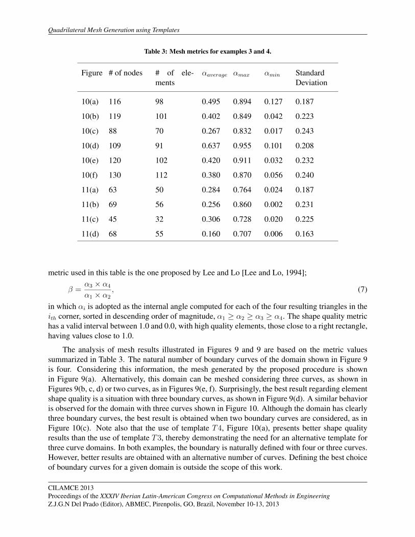
Table 3: Mesh metrics for examples 3 and 4.
Figure # of nodes # of ele-ments
αaverage αmax αmin StandardDeviation
10(a) 116 98 0.495 0.894 0.127 0.187
10(b) 119 101 0.402 0.849 0.042 0.223
10(c) 88 70 0.267 0.832 0.017 0.243
10(d) 109 91 0.637 0.955 0.101 0.208
10(e) 120 102 0.420 0.911 0.032 0.232
10(f) 130 112 0.380 0.870 0.056 0.240
11(a) 63 50 0.284 0.764 0.024 0.187
11(b) 69 56 0.256 0.860 0.002 0.231
11(c) 45 32 0.306 0.728 0.020 0.225
11(d) 68 55 0.160 0.707 0.006 0.163
metric used in this table is the one proposed by Lee and Lo [Lee and Lo, 1994];
β =α3 × α4
α1 × α2
, (7)
in which αi is adopted as the internal angle computed for each of the four resulting triangles in theith corner, sorted in descending order of magnitude, α1 ≥ α2 ≥ α3 ≥ α4. The shape quality metrichas a valid interval between 1.0 and 0.0, with high quality elements, those close to a right rectangle,having values close to 1.0.
The analysis of mesh results illustrated in Figures 9 and 9 are based on the metric valuessummarized in Table 3. The natural number of boundary curves of the domain shown in Figure 9is four. Considering this information, the mesh generated by the proposed procedure is shownin Figure 9(a). Alternatively, this domain can be meshed considering three curves, as shown inFigures 9(b, c, d) or two curves, as in Figures 9(e, f). Surprisingly, the best result regarding elementshape quality is a situation with three boundary curves, as shown in Figure 9(d). A similar behavioris observed for the domain with three curves shown in Figure 10. Although the domain has clearlythree boundary curves, the best result is obtained when two boundary curves are considered, as inFigure 10(c). Note also that the use of template T4, Figure 10(a), presents better shape qualityresults than the use of template T3, thereby demonstrating the need for an alternative template forthree curve domains. In both examples, the boundary is naturally defined with four or three curves.However, better results are obtained with an alternative number of curves. Defining the best choiceof boundary curves for a given domain is outside the scope of this work.
CILAMCE 2013Proceedings of the XXXIV Iberian Latin-American Congress on Computational Methods in EngineeringZ.J.G.N Del Prado (Editor), ABMEC, Pirenpolis, GO, Brazil, November 10-13, 2013

A.C.O. Miranda and L.F. Martha
5 Conclusion
This work presented a hierarchical template-based quadrilateral meshing scheme. Six tem-plates were presented: three templates with four curves, two with three curves and one with twocurves. The main concept of the proposed approach is to decompose a region into subregions, ina recursive and hierarchical way, until achieving a subregion in which it is possible to generatequadrilateral elements using the bilinear mapping technique. Meshes of all subregions are mergedto obtain one final mesh.
Template decomposition is based on discrete bilinear and trilinear projectors of parametriccoordinates on boundary curves. Details of the main procedures were described to help readersimplement them. Some of the contributions are:
• Two existing templates from the literature for a region with four curves wereimproved in terms of domain decomposition;
• An existing template (trimapping technique) for a region with three curves wasextended, and a restriction was removed by adding an offset correction;
• An alternative template with three curves was proposed;
• A new template with two curves was proposed.
Some examples were presented, showing the behaviour of the proposed meshing scheme whenthe number of edges of boundary curves is modified, and when different curves are considered asinput for a region. These examples demonstrate how useful the proposed alternative template isfor a region with three boundary curves. In addition, they demonstrate that the original number ofcurves of certain domains does not necessarily result in the best mesh when applying the proposedapproach. Other possibilities must be tested. Finally, the proposed templates were used to createtopologically equivalent source and target surface meshes in volumetric mesh generation using asweeping technique.
Acknowledgements The authors would like to thank the National Council for Scientific andTechnological Development (CNPq), University of Braslia, the Computer Graphics TechnologyGroup (Tecgraf) and Pontifical Catholic University of Rio de Janeiro (PUC-Rio) for the financialsupport and for providing the necessary space and resources used during the development of thiswork.
CILAMCE 2013Proceedings of the XXXIV Iberian Latin-American Congress on Computational Methods in Engineering
Z.J.G.N Del Prado (Editor), ABMEC, Pirenpolis, GO, Brazil, November 10-13, 2013
References
[Ansys, 2013] Ansys, I. (2013). Documentation for Ansys - Transition Mapped QuadrilateralMeshing. Ansys Inc.
[Baehmann et al., 1987] Baehmann, P. L., Wittchen, S. L., Shephard, M. S., Grice, K. R., andYerry, M. A. (1987). Robust, geometrically based, automatic two-dimensional mesh generation.International Journal for Numerical Methods in Engineering, 24(6):1043–1078.
[Cook, 1974] Cook, W. A. (1974). Body oriented (natural) co-ordinates for generating three di-mensional meshes. International Journal for Numerical Methods in Engineering, 8:27–43.
[Cook and Oakes, 1982] Cook, W. A. and Oakes, W. R. (1982). Mapping methods for generationthree-dimensional meshes. Computer In Mechanical Engineering, pages 67–72.
[Daniels et al., 2011] Daniels, J., Lizier, M., Siqueira, M., Silva, C., and Nonato, L. (2011).Template-based quadrilateral meshing. Computers & Graphics, 35(3):471–482.
[Gordon and Hall, 1973] Gordon, W. J. and Hall, C. A. (1973). Contruction of curvilinear co-ordinate systems and aplications to mesh generation. International Journal for Numerical Meth-ods in Engineering, 7:461–477.
[Haber and Abel, 1982] Haber, R. and Abel, J. F. (1982). Discrete transfinite mappings for de-scription and meshing of three-dimensional surfaces using interactive computer graphics. Inter-national Journal for Numerical Methods in Engineering, 18:41–66.
[Haber et al., 1981] Haber, R., Shephard, M. S., Abel, J., Gallagher, R., and Greenberg, D. (1981).A general two-dimensional, graphical finite element preprocessor utilizing discrete transfinitemapping. International Journal for Numerical Methods in Engineering, 17:1015–1044.
[Ito et al., 2009] Ito, Y., Shih, A., and Soni, B. (2009). Octree-based reasonable-quality hexahedralmesh generation using a new set of refinement templates. International Jornal For NumericalMethods in Enginnering, 77:1809–1833.
[Lee and Lo, 1994] Lee, C. K. and Lo, S. H. (1994). A new scheme for the generation of a gradedquadrilateral mesh. Computers and Structures, 52:847–857.
[Liang et al., 2010] Liang, X., Ebeida, M., and Zhang, Y. (2010). Guaranteed-quality all-quadrilateral mesh generation with feature preservation. Computer Methods in Applied Me-chanics and Engineering, 199:2072–2083.
19

Quadrilateral Mesh Generation using Templates
[Lizier M. and L., 2011] Lizier M., Siqueira M., D. J. S. C. and L., N. (2011). Template-basedquadrilateral mesh generation from imaging data. The Visual Computer, 27(10):887–903.
[Mitchell, 1999] Mitchell, S. (1999). The all-hex geode-template for conforming a diced tetrahe-dral mesh to any diced hexahedral mesh. Engineering with Computers, 15:228–235.
[Mitchell, 2000] Mitchell, S. A. (2000). High fidelity interval assignment. International Journalof Computatinal Geometry and Applications, 10(4):399–415.
[Muller-Hannemann, 2000] Muller-Hannemann, M. (2000). High quality quadrilateral surfacemeshing without template restrictions: A new approach based on network flow techniques. In-ternational Journal of Computational Geometry and Applications, 10(3):285–307.
[Nowottnys, 1997] Nowottnys, D. (1997). Quadrilateral mesh generation via geometrically opti-mized domain decomposition. In Proceedings of 6th International Meshing Roundtable, pages309–320.
[Perucchio et al., 1982] Perucchio, R., Ingraffea, A. R., and Abel, J. F. (1982). Interative computergraphics preprocessing for three-dimensional finite element analysis. International Journal forNumerical Methods in Engineering, 18:909–926.
[Samet, 1984] Samet, H. (1984). The quadtree and related hierarchial data structures. ACM Com-puter Surveys, 6(2):187–260.
[Schneiders, 2000] Schneiders, R. (2000). Algorithms for quadrilateral and hexahedral mesh gen-eration. In Proceedings of the VKI Lecture Series on Computational Fluid Dynamic.
[Schneiders et al., 1996] Schneiders, R., Schindler, R., and Weiler, F. (1996). Octree-based gener-ation of hexahedral element meshes. In Proceedings of 5th International Meshing Roundtable,pages 205–215.
[Smith and Johnston, 1996] Smith, R. J. and Johnston, L. J. (1996). Automatic grid generationand flow solution for complex geometries. Reston, VA, ETATS-UNIS: American Institute ofAeronautics and Astronautics.
[Staten et al., 2010] Staten, M., Kerr, R., Owen, S., Blacker, T., Stupazzini, M., and Shimada,K. (2010). Unconstrained plasteringhexahedral mesh generation via advancing-front geometrydecomposition. International Journal for Numerical Methods in Engineering, 81(2):135–171.
[Thompson et al., 1999] Thompson, J., Soni, B., and Weatherill, N. (1999). Handbook of gridgeneration. CRC Press.
[Yamakawa and Shimada, 2001] Yamakawa, S. and Shimada, K. (2001). Hexhoop: Modular tem-plates for converting a hex-dominant mesh to an all-hex mesh. In Proceedings of 10th Interna-tional Meshing Roundtable, pages 235–246.
[Yerry and Shephard, 1983] Yerry, M. and Shephard, M. (1983). A modified quadtree approach tofinite element mesh generation. IEEE Computer Graphics and Applications, 3(1):39–46.
[Yerry and Shephard, 1984] Yerry, M. and Shephard, M. (1984). Automatic three-dimensionalmesh generation by the modified-octree technique. International Journal for Numerical Methods
CILAMCE 2013Proceedings of the XXXIV Iberian Latin-American Congress on Computational Methods in EngineeringZ.J.G.N Del Prado (Editor), ABMEC, Pirenpolis, GO, Brazil, November 10-13, 2013

A.C.O. Miranda and L.F. Martha
in Engineering, 20(11):1965–1990.
[Yiu et al., 1996] Yiu, K., Greaves, D., Cruz, S., Saalehi, A., and Borthwick, A. (1996). Quadtreegrid generation: Information handling, boundary fitting and cfd applications. Computers &Fluids, 25(8):759–769.
[Zhang and Zhao, 2007] Zhang, H. and Zhao, G. (2007). Adaptive hexahedral mesh generationbased on local domain curvature and thickness using a modified grid-based method. FiniteElements in Analysis and Design, 43(9):691–704.
CILAMCE 2013Proceedings of the XXXIV Iberian Latin-American Congress on Computational Methods in Engineering
Z.J.G.N Del Prado (Editor), ABMEC, Pirenpolis, GO, Brazil, November 10-13, 2013