QSE (Q-Star) Series Electromagnetic Meter Owner’s...
20
920896-01 Rev P 04/2018 QSE (Q-Star) Series Electromagnetic Meter Owner’s Manual NPT Meter (1/2 in. to 2 in.) Shown with Display Mount Cover Plate and Display BSPP Meter (1/2 in. to 2 in.) Shown with Display Mount Cover Plate and Display ANSI Flanged Meter (3 in. & 4 in.) Shown with Plain Cover Plate and Pulse Out Transmitter (QSB) INTRODUCTION The QSE meter has multiple types of output electronics available. The electronics for the operation of the meter coils and flow tube are housed within the meter body casing. The cover plate is designed in two versions; a plain cover plate or a display mount cover plate. The output electronics (QSB, QSI1, QSI2 or QSI3) can be housed within either of the two cover plates. A display (Q09) is also available mounted to the “display mount” cover plate. All meters are equipped with galvanically isolated pulse-out electronics (QSB) as the default standard, regardless of style of cover plate. This manual contains overall information related only to the meter. This meter is externally powered and all external wiring connects to the electronics within the cover plate through its threaded ports. TABLE OF CONTENTS INTRODUCTION ..................................... 1 IMPORTANT NOTICE ....................... 2 PRINCIPLE OF OPERATION ............ 2 SAFETY ............................................ 2 INSTALLATION ....................................... 3 EARTH GROUND ............................. 3 TYPICAL INSTALLATION.................. 3 CONNECTIONS ............................... 4 RECOMMENDED INSTALLATION .... 6 WIRING ............................................ 7 MAINTENANCE ...................................... 7 TROUBLESHOOTING ............................ 8 SPECIFICATIONS ................................... 9 U.S. MEASUREMENT .................... 10 METRIC MEASUREMENT .............. 11 U.S. PRODUCT WEIGHT ............... 12 METRIC PRODUCT WEIGHT ......... 12 DIMENSIONS ................................. 13 TEMPERATURES ........................... 14 FLUID ELECTRICAL CONDUCTIVITY .. 15 REPLACEMENT PARTS LIST ............... 16 SERVICE............................................... 18 LIMITED WARRANTY ........................... 20
Transcript of QSE (Q-Star) Series Electromagnetic Meter Owner’s...
920896-01 Rev P04/2018
QSE (Q-Star) Series Electromagnetic Meter
Owner’s Manual
NPT OR BSP METER
WITH 09 ELECTRONICS
3" POLYMER FLANGE METER WITH QB ELECTRONICS
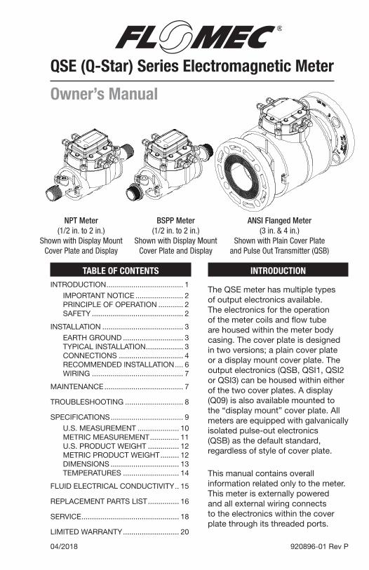
NPT Meter(1/2 in. to 2 in.)
Shown with Display Mount Cover Plate and Display
BSPP Meter(1/2 in. to 2 in.)
Shown with Display Mount Cover Plate and Display
ANSI Flanged Meter(3 in. & 4 in.)
Shown with Plain Cover Plate and Pulse Out Transmitter (QSB)
INTRODUCTION
The QSE meter has multiple types of output electronics available. The electronics for the operation of the meter coils and flow tube are housed within the meter body casing. The cover plate is designed in two versions; a plain cover plate or a display mount cover plate. The output electronics (QSB, QSI1, QSI2 or QSI3) can be housed within either of the two cover plates. A display (Q09) is also available mounted to the “display mount” cover plate. All meters are equipped with galvanically isolated pulse-out electronics (QSB) as the default standard, regardless of style of cover plate.
This manual contains overall information related only to the meter. This meter is externally powered and all external wiring connects to the electronics within the cover plate through its threaded ports.
TABLE OF CONTENTSINTRODUCTION ..................................... 1
IMPORTANT NOTICE ....................... 2PRINCIPLE OF OPERATION ............ 2SAFETY ............................................ 2
INSTALLATION ....................................... 3
EARTH GROUND ............................. 3TYPICAL INSTALLATION .................. 3CONNECTIONS ............................... 4RECOMMENDED INSTALLATION .... 6WIRING ............................................ 7
MAINTENANCE ...................................... 7
TROUBLESHOOTING ............................ 8
SPECIFICATIONS ................................... 9
U.S. MEASUREMENT .................... 10METRIC MEASUREMENT .............. 11U.S. PRODUCT WEIGHT ............... 12METRIC PRODUCT WEIGHT ......... 12DIMENSIONS ................................. 13TEMPERATURES ........................... 14
FLUID ELECTRICAL CONDUCTIVITY .. 15
REPLACEMENT PARTS LIST ............... 16
SERVICE ............................................... 18
LIMITED WARRANTY ........................... 20
BSPP METER WITH
09 ELECTRONICS
2
The magnetic coils, electrodes and other electronic components within the main meter body receive power from the electronics housed within the cover plate through a ribbon cable. See the included electronics manuals for meter wiring diagrams specific to your meter electronics.
IMPORTANT NOTICE
Your QSE meter is supplied ready for operation in a wide variety of applications. The meter has been factory configured to your order. It is suitable for volumetric flow measurement of non-flammable, electrically conductive liquids that have a minimum fluid conductivity of 10 µS/cm, and are compatible with the wetted components of the meter (See Specification Section).
Fluid conductivity below 50 µS/cm may result in uncertain readings. Consult factory for use with fluids having a conductivity below 50 µS/cm.
Use QSE series meters with water, aqueous solutions and other non-flammable, electrically conductive fluids. A fluid conductivity chart of common liquids is in the back of this manual for your reference. Do not use the meter with petroleum products (diesel fuel, unleaded gasoline, jet fuel, kerosene, etc.) or incompatible chemicals.
QSE series meters are very sensitive to electric noise if operated within 6 inches (152mm) of some electric motors, relays, transformers or other sources of electronic noise.
If the QSE series meters are used in a manner not specified by the manufacturer, the protection provided by the equipment may be impaired.
PRINCIPLE OF OPERATION
Faraday’s Law of Electromagnetic Induction is the operating principle on which the QSE series meters are based. Faraday’s Law (paraphrased) states that a voltage will be induced in a conductor when it passes through a magnetic field, and the induced voltage will be directly proportional to the velocity of the conductor passing through that magnetic field. In this case, flowing liquid is the conductor and the QSE meter creates the magnetic field. The velocity of the flowing liquid, which must pass through the magnetic field, is the velocity of the conductor. A voltage is induced in the conductive liquid as it passes through the magnetic field. By placing electrodes in calculated locations on the flow tube of the meter, it is possible to accurately measure the induced voltage, thus determining the corresponding velocity and volumetric flow of the liquid.
SAFETY
• This product is not approved for use with petroleum products (diesel fuel, unleaded gasoline, jet fuel, kerosene, etc.), aromatic hydrocarbons, flammable fluids or other incompatible chemicals
• This product is not approved for use in hazardous locations.
• Be sure O-rings and seals are kept in good repair.
• When applying power, adhere to specifications listed in appropriate electronics manual.
• Disconnect external power before attaching or detaching input or output wires.
3
INSTALLATION
EARTH GROUND
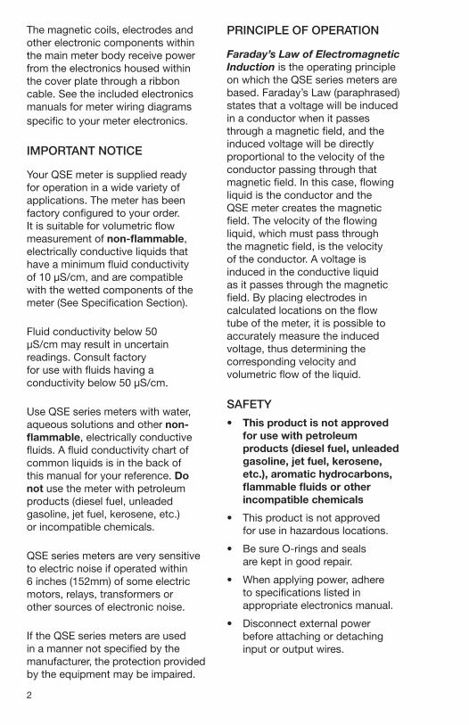
As part of the installation, it is important to understand the importance of having the meter connected to “earth ground”. Earth grounding helps ensure electronic component stability and reliability by using the earth to absorb any static charge buildup or spurious signal noise that can affect the meter electronics.
Each meter has a ground lug with removable ring terminal located in the circular wall adjacent to the outlet end of the meter. One end of a customer supplied 14-16 AWG ground wire should be crimped to the ring terminal and the other end of the wire connected to earth ground. (See Figure 1 below.)
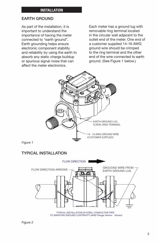
FLOW DIRECTION
TYPICAL INSTALLATION IN STEEL CONDUCTIVE PIPETO MAINTAIN GROUND CONTINUITY (ANSI Flange Version Shown)
FLOW DIRECTION ARROWSGROUOND WIRE FROMEARTH GROUND LUG
920896-01H GRAPHIC
TYPICAL INSTALLATION
EARTH GROUND LUG,SCREW, RING TERMINAL
14 - 16 AWG GROUND WIRE(CUSTOMER SUPPLIED)
920896-01H GRAPHIC
Figure 2
Figure 1
4
CONNECTIONS
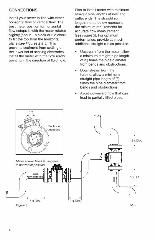
Install your meter in-line with either horizontal flow or vertical flow. The best meter position for horizontal flow setups is with the meter rotated slightly (about 1 o’clock or 2 o’clock) to tilt the top from the horizontal plane (see Figures 2 & 3). This prevents sediment from settling on the lower set of sensing electrodes. Install the meter with the flow arrow pointing in the direction of fluid flow.
Plan to install meter with minimum straight pipe lengths at inlet and outlet ends. The straight run lengths noted below represent the minimum requirements for accurate flow measurement (see Figure 3). For optimum performance, provide as much additional straight run as possible.
• Upstream from the meter, allow a minimum straight pipe length of (5) times the pipe diameter from bends and obstructions.
• Downstream from the turbine, allow a minimum straight pipe length of (3) times the pipe diameter from bends and obstructions.
• Avoid downward flow that can lead to partially filled pipes.
5 x DIA.
3 x DIA.
5 x DIA. 3 x DIA.
FLOW DIRECTION
FLO
W D
IRE
CT
ION
20˚
Electrode Locations
5 x DIA.
3 x DIA.
5 x DIA. 3 x DIA.
FLOW DIRECTION
FLO
W D
IRE
CT
ION
Figure 3
Meter shown tilted 20 degrees in horizontal position
5
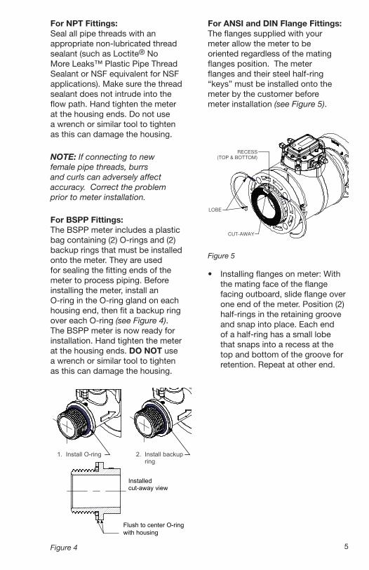
For NPT Fittings: Seal all pipe threads with an appropriate non-lubricated thread sealant (such as Loctite® No More Leaks™ Plastic Pipe Thread Sealant or NSF equivalent for NSF applications). Make sure the thread sealant does not intrude into the flow path. Hand tighten the meter at the housing ends. Do not use a wrench or similar tool to tighten as this can damage the housing.
NOTE: If connecting to new female pipe threads, burrs and curls can adversely affect accuracy. Correct the problem prior to meter installation.
For BSPP Fittings: The BSPP meter includes a plastic bag containing (2) O-rings and (2) backup rings that must be installed onto the meter. They are used for sealing the fitting ends of the meter to process piping. Before installing the meter, install an O-ring in the O-ring gland on each housing end, then fit a backup ring over each O-ring (see Figure 4). The BSPP meter is now ready for installation. Hand tighten the meter at the housing ends. DO NOT use a wrench or similar tool to tighten as this can damage the housing.
1. Install O-ring 2. Install backup ring
Installed
Flush to center O-ring with housing
cut-away view
Figure 4
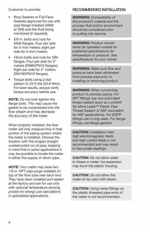
For ANSI and DIN Flange Fittings: The flanges supplied with your meter allow the meter to be oriented regardless of the mating flanges position. The meter flanges and their steel half-ring “keys” must be installed onto the meter by the customer before meter installation (see Figure 5).
LOBE
RECESS
(TOP & BOTTOM)
FLANGE INSTALLATION
(POLYMER FLANGE SHOWN)
CUT-AWAY
Figure 5
• Installing flanges on meter: With the mating face of the flange facing outboard, slide flange over one end of the meter. Position (2) half-rings in the retaining groove and snap into place. Each end of a half-ring has a small lobe that snaps into a recess at the top and bottom of the groove for retention. Repeat at other end.
6
Customer to provide:
• Ring Gaskets or Full-Face Gaskets approved for use with type flange installed (ANSI or DIN) and the fluid being monitored (2 required).
• 5/8 in. bolts and nuts for ANSI flanges. Four per side for 3-inch meters; eight per side for 4-inch meters.
• 16mm bolts and nuts for DIN flanges. Four per side for 3” meters (DN80/PN10 flanges); Eight per side for 4” meters (DN100/PN10 flanges).
• Torque bolts using a star pattern to 25 ft-lbs (33.9 N•m). For best results, always verify torque accuracy before use.
NOTE: Do not over tighten the flange bolts. This may cause the gasket to be compressed into the flow stream and may decrease the accuracy of the meter.
When properly installed, the flow meter will only measure flow in that portion of the piping system where the meter is installed. Choose the location with the longest straight unobstructed run of pipe, keeping in mind that in some applications it may be possible to locate the meter in either the supply or return pipe.
NOTE: Your meter may have two 1/8 in. NPT pipe plugs installed on top of the flow tube near each end. They have been installed and sealed at the factory and are for use only with optional temperature sensing probes for energy use calculations in specialized applications.
RECOMMENDED INSTALLATION
WARNING: Compatibility of this product’s material and the process fluid and/or environment should be considered prior to putting into service.
WARNING: Product should never be operated outside its published specifications for temperature or pressure. See specifications for your model.
WARNING: Make sure flow and pressure have been eliminated from process pipe prior to installing or removing product.
WARNING: When connecting product to process piping: For NPT fittings use non-lubricated thread sealant (such as Loctite® No More Leaks™ Plastic Pipe Thread Sealant or NSF equivalent for NSF applications). For BSPP fittings use O-ring seals. For flange fittings use flange gaskets.
CAUTION: Installation near high electromagnetic fields and high current fields is not recommended and may result in inaccurate readings.
CAUTION: Do not allow water to freeze in meter. Ice expansion may burst the plastic housing.
CAUTION: Do not allow this meter to be used with steam.
CAUTION: Using metal fittings on the plastic threaded pipe ends of the meter is not recommended.
7
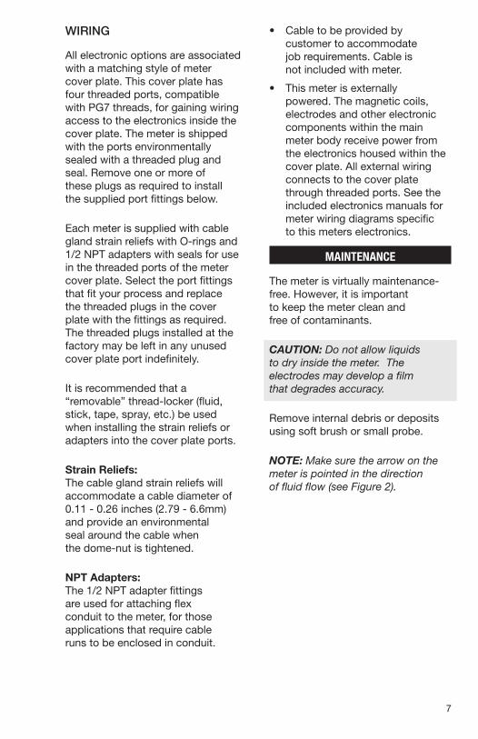
WIRING
All electronic options are associated with a matching style of meter cover plate. This cover plate has four threaded ports, compatible with PG7 threads, for gaining wiring access to the electronics inside the cover plate. The meter is shipped with the ports environmentally sealed with a threaded plug and seal. Remove one or more of these plugs as required to install the supplied port fittings below.
Each meter is supplied with cable gland strain reliefs with O-rings and 1/2 NPT adapters with seals for use in the threaded ports of the meter cover plate. Select the port fittings that fit your process and replace the threaded plugs in the cover plate with the fittings as required. The threaded plugs installed at the factory may be left in any unused cover plate port indefinitely.
It is recommended that a “removable” thread-locker (fluid, stick, tape, spray, etc.) be used when installing the strain reliefs or adapters into the cover plate ports.
Strain Reliefs: The cable gland strain reliefs will accommodate a cable diameter of 0.11 - 0.26 inches (2.79 - 6.6mm) and provide an environmental seal around the cable when the dome-nut is tightened.
NPT Adapters: The 1/2 NPT adapter fittings are used for attaching flex conduit to the meter, for those applications that require cable runs to be enclosed in conduit.
• Cable to be provided by customer to accommodate job requirements. Cable is not included with meter.
• This meter is externally powered. The magnetic coils, electrodes and other electronic components within the main meter body receive power from the electronics housed within the cover plate. All external wiring connects to the cover plate through threaded ports. See the included electronics manuals for meter wiring diagrams specific to this meters electronics.
MAINTENANCE
The meter is virtually maintenance-free. However, it is important to keep the meter clean and free of contaminants.
CAUTION: Do not allow liquids to dry inside the meter. The electrodes may develop a film that degrades accuracy.
Remove internal debris or deposits using soft brush or small probe.
NOTE: Make sure the arrow on the meter is pointed in the direction of fluid flow (see Figure 2).
8
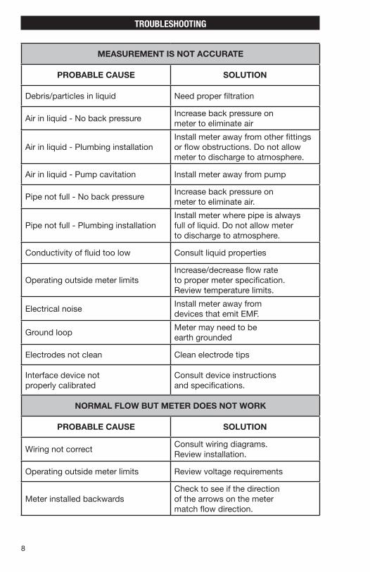
TROUBLESHOOTING
MEASUREMENT IS NOT ACCURATE
PROBABLE CAUSE SOLUTION
Debris/particles in liquid Need proper filtration
Air in liquid - No back pressureIncrease back pressure on meter to eliminate air
Air in liquid - Plumbing installationInstall meter away from other fittings or flow obstructions. Do not allow meter to discharge to atmosphere.
Air in liquid - Pump cavitation Install meter away from pump
Pipe not full - No back pressureIncrease back pressure on meter to eliminate air.
Pipe not full - Plumbing installationInstall meter where pipe is always full of liquid. Do not allow meter to discharge to atmosphere.
Conductivity of fluid too low Consult liquid properties
Operating outside meter limitsIncrease/decrease flow rate to proper meter specification. Review temperature limits.
Electrical noiseInstall meter away from devices that emit EMF.
Ground loopMeter may need to be earth grounded
Electrodes not clean Clean electrode tips
Interface device not properly calibrated
Consult device instructions and specifications.
NORMAL FLOW BUT METER DOES NOT WORK
PROBABLE CAUSE SOLUTION
Wiring not correctConsult wiring diagrams. Review installation.
Operating outside meter limits Review voltage requirements
Meter installed backwardsCheck to see if the direction of the arrows on the meter match flow direction.
9
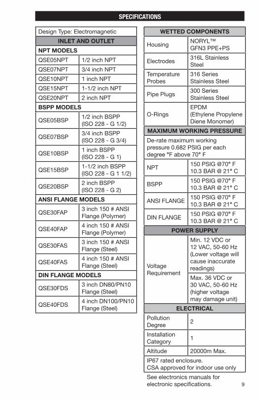
Design Type: Electromagnetic
INLET AND OUTLET
NPT MODELS
QSE05NPT 1/2 inch NPT
QSE07NPT 3/4 inch NPT
QSE10NPT 1 inch NPT
QSE15NPT 1-1/2 inch NPT
QSE20NPT 2 inch NPT
BSPP MODELS
QSE05BSP1/2 inch BSPP (ISO 228 - G 1/2)
QSE07BSP3/4 inch BSPP (ISO 228 - G 3/4)
QSE10BSP1 inch BSPP (ISO 228 - G 1)
QSE15BSP1-1/2 inch BSPP (ISO 228 - G 1 1/2)
QSE20BSP2 inch BSPP (ISO 228 - G 2)
ANSI FLANGE MODELS
QSE30FAP3 inch 150 # ANSI Flange (Polymer)
QSE40FAP4 inch 150 # ANSI Flange (Polymer)
QSE30FAS3 inch 150 # ANSI Flange (Steel)
QSE40FAS4 inch 150 # ANSI Flange (Steel)
DIN FLANGE MODELS
QSE30FDS3 inch DN80/PN10 Flange (Steel)
QSE40FDS4 inch DN100/PN10 Flange (Steel)
WETTED COMPONENTS
HousingNORYL™ GFN3 PPE+PS
Electrodes316L Stainless Steel
Temperature Probes
316 Series Stainless Steel
Pipe Plugs300 Series Stainless Steel
O-RingsEPDM (Ethylene Propylene Diene Monomer)
MAXIMUM WORKING PRESSURE
De-rate maximum working pressure 0.682 PSIG per each degree °F above 70° F
NPT150 PSIG @70° F 10.3 BAR @ 21° C
BSPP150 PSIG @70° F 10.3 BAR @ 21° C
ANSI FLANGE150 PSIG @70° F 10.3 BAR @ 21° C
DIN FLANGE150 PSIG @70° F 10.3 BAR @ 21° C
POWER SUPPLY
Voltage Requirement
Min. 12 VDC or 12 VAC, 50-60 Hz (Lower voltage will cause inaccurate readings)
Max. 36 VDC or 30 VAC, 50-60 Hz (higher voltage may damage unit)
ELECTRICAL
Pollution Degree
2
Installation Category
1
Altitude 20000m Max.
IP67 rated enclosure. CSA approved for indoor use only
See electronics manuals for electronic specifications.
SPECIFICATIONS
10
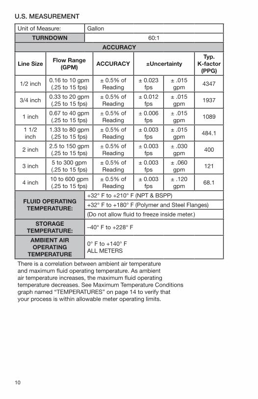
U.S. MEASUREMENT
Unit of Measure: Gallon
TURNDOWN 60:1
ACCURACY
Line SizeFlow Range
(GPM)ACCURACY ±Uncertainty
Typ. K-factor
(PPG)
1/2 inch0.16 to 10 gpm (.25 to 15 fps)
± 0.5% of Reading
± 0.023 fps
± .015 gpm
4347
3/4 inch0.33 to 20 gpm (.25 to 15 fps)
± 0.5% of Reading
± 0.012 fps
± .015 gpm
1937
1 inch0.67 to 40 gpm (.25 to 15 fps)
± 0.5% of Reading
± 0.006 fps
± .015 gpm
1089
1 1/2 inch
1.33 to 80 gpm (.25 to 15 fps)
± 0.5% of Reading
± 0.003 fps
± .015 gpm
484.1
2 inch2.5 to 150 gpm (.25 to 15 fps)
± 0.5% of Reading
± 0.003 fps
± .030 gpm
400
3 inch5 to 300 gpm (.25 to 15 fps)
± 0.5% of Reading
± 0.003 fps
± .060 gpm
121
4 inch10 to 600 gpm (.25 to 15 fps)
± 0.5% of Reading
± 0.003 fps
± .120 gpm
68.1
FLUID OPERATING TEMPERATURE:
+32° F to +210° F (NPT & BSPP)
+32° F to +180° F (Polymer and Steel Flanges)
(Do not allow fluid to freeze inside meter.)
STORAGE TEMPERATURE:
–40° F to +228° F
AMBIENT AIR OPERATING
TEMPERATURE
0° F to +140° F ALL METERS
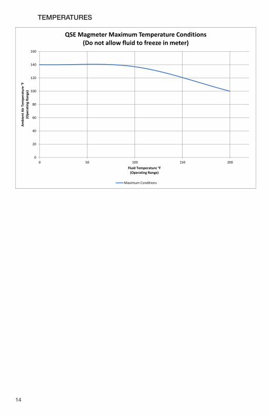
There is a correlation between ambient air temperature and maximum fluid operating temperature. As ambient air temperature increases, the maximum fluid operating temperature decreases. See Maximum Temperature Conditions graph named “TEMPERATURES” on page 14 to verify that your process is within allowable meter operating limits.
11
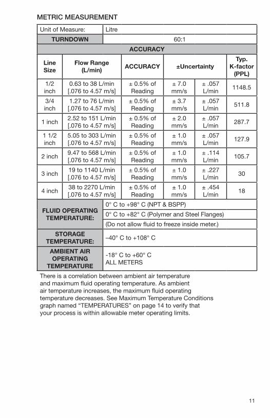
METRIC MEASUREMENT
Unit of Measure: Litre
TURNDOWN 60:1
ACCURACY
Line Size
Flow Range (L/min)
ACCURACY ±UncertaintyTyp.
K-factor (PPL)
1/2 inch
0.63 to 38 L/min [.076 to 4.57 m/s]
± 0.5% of Reading
± 7.0 mm/s
± .057 L/min
1148.5
3/4 inch
1.27 to 76 L/min [.076 to 4.57 m/s]
± 0.5% of Reading
± 3.7 mm/s
± .057 L/min
511.8
1 inch2.52 to 151 L/min [.076 to 4.57 m/s]
± 0.5% of Reading
± 2.0 mm/s
± .057 L/min
287.7
1 1/2 inch
5.05 to 303 L/min [.076 to 4.57 m/s]
± 0.5% of Reading
± 1.0 mm/s
± .057 L/min
127.9
2 inch9.47 to 568 L/min [.076 to 4.57 m/s]
± 0.5% of Reading
± 1.0 mm/s
± .114 L/min
105.7
3 inch19 to 1140 L/min [.076 to 4.57 m/s]
± 0.5% of Reading
± 1.0 mm/s
± .227 L/min
30
4 inch38 to 2270 L/min [.076 to 4.57 m/s]
± 0.5% of Reading
± 1.0 mm/s
± .454 L/min
18
FLUID OPERATING TEMPERATURE:
0° C to +98° C (NPT & BSPP)
0° C to +82° C (Polymer and Steel Flanges)
(Do not allow fluid to freeze inside meter.)
STORAGE TEMPERATURE:
–40° C to +108° C
AMBIENT AIR OPERATING
TEMPERATURE
-18° C to +60° C ALL METERS
There is a correlation between ambient air temperature and maximum fluid operating temperature. As ambient air temperature increases, the maximum fluid operating temperature decreases. See Maximum Temperature Conditions graph named “TEMPERATURES” on page 14 to verify that your process is within allowable meter operating limits.
12
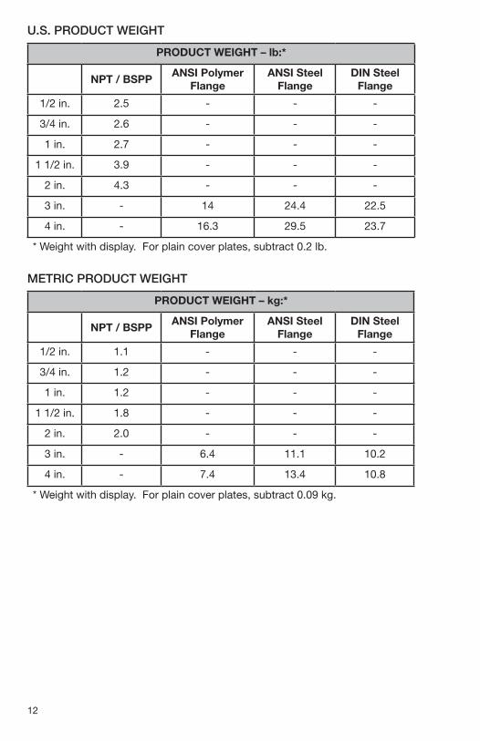
PRODUCT WEIGHT – kg:*
NPT / BSPPANSI Polymer
FlangeANSI Steel
FlangeDIN Steel
Flange
1/2 in. 1.1 - - -
3/4 in. 1.2 - - -
1 in. 1.2 - - -
1 1/2 in. 1.8 - - -
2 in. 2.0 - - -
3 in. - 6.4 11.1 10.2
4 in. - 7.4 13.4 10.8
* Weight with display. For plain cover plates, subtract 0.09 kg.
PRODUCT WEIGHT – lb:*
NPT / BSPPANSI Polymer
FlangeANSI Steel
FlangeDIN Steel
Flange
1/2 in. 2.5 - - -
3/4 in. 2.6 - - -
1 in. 2.7 - - -
1 1/2 in. 3.9 - - -
2 in. 4.3 - - -
3 in. - 14 24.4 22.5
4 in. - 16.3 29.5 23.7
* Weight with display. For plain cover plates, subtract 0.2 lb.
U.S. PRODUCT WEIGHT
METRIC PRODUCT WEIGHT
13
C A
NPT / BSPP WITH 09 ELECTRONICS NPT / BSPP WITH QB ELECTRONICS
B DE
QSE METER DIMENSIONS (NPT, BSP, FLANGE)
METER SIZE & FITTING A B C D E
1/2 in. NPT & BSP 5.20 [132.1] 5.83 [148.1] 10.50 [266.7] 5.13 [130.3] 1.83 [46.5]
3/4 in. NPT & BSP 5.20 [132.1] 5.83 [148.1] 10.75 [273.1] 5.13 [130.3] 1.83 [46.5]
1 in. NPT & BSP 5.20 [132.1] 5.83 [148.1] 11.00 [279.4] 5.13 [130.3] 1.83 [46.5]
1 1/2 in. NPT & BSP 5.22 [132.6] 6.95 [176.5] 11.00 [279.4] 6.25 [158.8] 2.37 [60.2]
2 in. NPT & BSP 5.22 [132.6] 6.95 [176.5] 11.00 [279.4] 6.25 [158.8] 2.37 [60.2]
3 in Flange 7.50 [190.5] 9.62 [244.3] 12.00 [304.8] 8.92 [226.6] 3.25 [82.6]
4in. Flange 9.00 [228.6] 10.37 [263.4] 12.00 [304.8] 9.67 [245.6] 4.50 [114.3]
FLANGE WITH 09 ELECTRONICS FLANGE WITH QB ELECTRONICS
A
B
E
D
C
MILLIMETER DIMENSIONS SHOWN IN BRACKETS
6.31[160.2]
ALL METERS
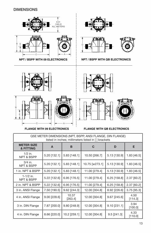
DIMENSIONS
QSE METER DIMENSIONS (NPT, BSPP, ANSI FLANGE, DIN FLANGE) listed in inches; millimeters listed in [ ] brackets
METER SIZE & FITTING A B C D E
1/2 in. NPT & BSPP 5.20 [132.1] 5.83 [148.1] 10.50 [266.7] 5.13 [130.9] 1.83 [46.5]
3/4 in. NPT & BSPP 5.20 [132.1] 5.83 [148.1] 10.75 [w273.1] 5.13 [130.9] 1.83 [46.5]
1 in. NPT & BSPP 5.20 [132.1] 5.83 [148.1] 11.00 [279.4] 5.13 [130.9] 1.83 [46.5]
1-1/2 in. NPT & BSPP 5.22 [132.6] 6.95 [176.5] 11.00 [279.4] 6.25 [158.8] 2.37 [60.2]
2 in. NPT & BSPP 5.22 [132.6] 6.95 [176.5] 11.00 [279.4] 6.25 [158.8] 2.37 [60.2]
3 in. ANSI Flange 7.50 [190.5] 9.62 [244.3] 12.00 [304.8] 8.92 [226.6] 3.75 [95.3]
4 in. ANSI Flange 9.00 [228.6] 10.37 [263.4] 12.00 [304.8] 9.67 [245.6] 4.50
[114.3]
3 in. DIN Flange 7.87 [200.0] 9.80 [248.9] 12.00 [304.8] 9.10 [231.1] 3.94 [100.0]
4 in. DIN Flange 8.66 [220.0] 10.2 [259.1] 12.00 [304.8] 9.5 [241.3] 4.33 [110.0]
14
TEMPERATURES
15
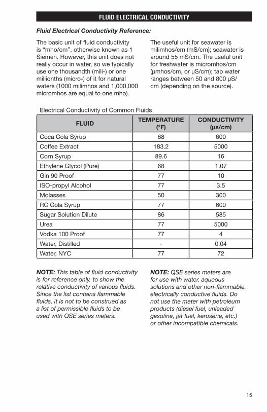
The useful unit for seawater is milimhos/cm (mS/cm); seawater is around 55 mS/cm. The useful unit for freshwater is micromhos/cm (µmhos/cm, or µS/cm); tap water ranges between 50 and 800 µS/cm (depending on the source).
The basic unit of fluid conductivity is “mho/cm”, otherwise known as 1 Siemen. However, this unit does not really occur in water, so we typically use one thousandth (mili-) or one millionths (micro-) of it for natural waters (1000 milimhos and 1,000,000 micromhos are equal to one mho).
FLUID ELECTRICAL CONDUCTIVITY
Fluid Electrical Conductivity Reference:
Electrical Conductivity of Common Fluids
FLUIDTEMPERATURE
(°F)CONDUCTIVITY
(µs/cm)
Coca Cola Syrup 68 600
Coffee Extract 183.2 5000
Corn Syrup 89.6 16
Ethylene Glycol (Pure) 68 1.07
Gin 90 Proof 77 10
ISO-propyl Alcohol 77 3.5
Molasses 50 300
RC Cola Syrup 77 600
Sugar Solution Dilute 86 585
Urea 77 5000
Vodka 100 Proof 77 4
Water, Distilled - 0.04
Water, NYC 77 72
NOTE: This table of fluid conductivity is for reference only, to show the relative conductivity of various fluids. Since the list contains flammable fluids, it is not to be construed as a list of permissible fluids to be used with QSE series meters.
NOTE: QSE series meters are for use with water, aqueous solutions and other non-flammable, electrically conductive fluids. Do not use the meter with petroleum products (diesel fuel, unleaded gasoline, jet fuel, kerosene, etc.) or other incompatible chemicals.
16
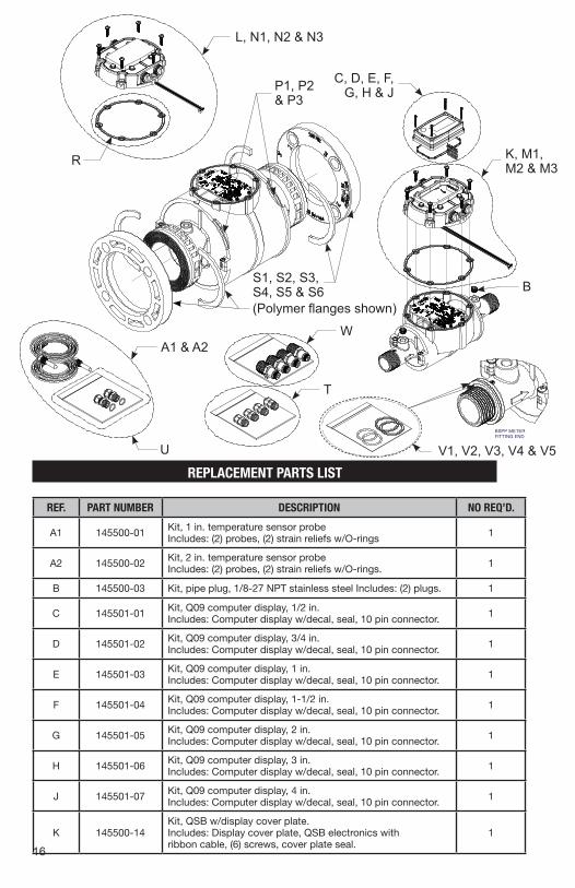
REPLACEMENT PARTS LIST
REF. PART NUMBER DESCRIPTION NO REQ’D.
A1 145500-01 Kit, 1 in. temperature sensor probe Includes: (2) probes, (2) strain reliefs w/O-rings 1
A2 145500-02 Kit, 2 in. temperature sensor probe Includes: (2) probes, (2) strain reliefs w/O-rings. 1
B 145500-03 Kit, pipe plug, 1/8-27 NPT stainless steel Includes: (2) plugs. 1
C 145501-01 Kit, Q09 computer display, 1/2 in. Includes: Computer display w/decal, seal, 10 pin connector. 1
D 145501-02 Kit, Q09 computer display, 3/4 in. Includes: Computer display w/decal, seal, 10 pin connector. 1
E 145501-03 Kit, Q09 computer display, 1 in. Includes: Computer display w/decal, seal, 10 pin connector. 1
F 145501-04 Kit, Q09 computer display, 1-1/2 in. Includes: Computer display w/decal, seal, 10 pin connector. 1
G 145501-05 Kit, Q09 computer display, 2 in. Includes: Computer display w/decal, seal, 10 pin connector. 1
H 145501-06 Kit, Q09 computer display, 3 in. Includes: Computer display w/decal, seal, 10 pin connector. 1
J 145501-07 Kit, Q09 computer display, 4 in. Includes: Computer display w/decal, seal, 10 pin connector. 1
K 145500-14Kit, QSB w/display cover plate. Includes: Display cover plate, QSB electronics with ribbon cable, (6) screws, cover plate seal.
1
BSPP METERFITTING END
920896-01REV. P
L, N1, N2 & N3
W
T
B
A1 & A2
U
P1, P2 & P3
S1, S2, S3, S4, S5 & S6(Polymer flanges shown)
V1, V2, V3, V4 & V5
R
C, D, E, F, G, H & J
K, M1, M2 & M3
17
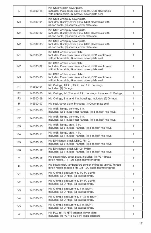
L 145500-15Kit, QSB w/plain cover plate. Includes: Plain cover plate w/decal, QSB electronics with ribbon cable, (6) screws, cover plate seal.
1
M1 145502-01Kit, QSI1 w/display cover plate. Includes: Display cover plate, QSI1 electronics with ribbon cable, (6) screws, cover plate seal.
1
M2 145502-02Kit, QSI2 w/display cover plate. Includes: Display cover plate, QSI2 electronics with ribbon cable, (6) screws, cover plate seal.
1
M3 145502-03Kit, QSI3 w/display cover plate. Includes: Display cover plate, QSI3 electronics with ribbon cable, (6) screws, cover plate seal.
1
N1 145503-01Kit, QSI1 w/plain cover plate. Includes: Plain cover plate w/decal, QSI1 electronics with ribbon cable, (6) screws, cover plate seal.
1
N2 145503-02Kit, QSI2 w/plain cover plate. Includes: Plain cover plate w/decal, QSI2 electronics with ribbon cable, (6) screws, cover plate seal.
1
N3 145503-03Kit, QSI3 w/plain cover plate. Includes: Plain cover plate w/decal, QSI3 electronics with ribbon cable, (6) screws, cover plate seal.
1
P1 145500-04 Kit, O-rings, 1/2 in., 3/4 in. and 1 in. housings. Includes: (2) O-rings. 1
P2 145500-05 Kit, O-rings, 1-1/2 in. and 2 in. housings. Includes: (2) O-rings. 1
P3 145500-06 Kit, O-rings, 3 in. and 4 in. housings. Includes: (2) O-rings. 1
R 145500-07 Kit, seal, cover plate. Includes: (1) Cover plate seal. 1
S1 145500-08 Kit, ANSI flange, polymer, 3 in. Includes: (2) 3 in. polymer flanges, (4) 3 in. half-ring keys. 1
S2 145500-09 Kit, ANSI flange, polymer, 4 in. Includes: (2) 4 in. polymer flanges, (4) 4 in. half-ring keys. 1
S3 145500-10 Kit, ANSI flange, steel, 3 in. Includes: (2) 3 in. steel flanges, (4) 3 in. half-ring keys. 1
S4 145500-11 Kit, ANSI flange, steel, 4 in. Includes: (2) 4 in. steel flanges, (4) 4 in. half-ring keys. 1
S5 145500-16 Kit, DIN flange, steel, DN80, PN10. Includes: (2) 3 in. steel flanges, (4) 3 in. half-ring keys. 1
S6 145500-17 Kit, DIN flange, steel, DN100, PN10. Includes: (2) 4 in. steel flanges, (4) 4 in. half-ring keys. 1
T 145500-12 Kit, strain relief, cover plate. Includes: (4) PG7 thread strain reliefs, .11 - .26 cable diameter range 1
U 145500-13 Kit, strain relief, temperature sensor. Includes: (2) PG7 thread strain reliefs (reduced fit), .08 - .20 cable diameter range 1
V1 145500-20 Kit, O-ring & backup ring, 1/2 in. BSPP. Includes: (2) O-rings, (2) backup rings. 1
V2 145500-21 Kit, O-ring & backup ring, 3/4 in. BSPP. Includes: (2) O-rings, (2) backup rings. 1
V3 145500-22 Kit, O-ring & backup ring, 1 in. BSPP. Includes: (2) O-rings, (2) backup rings. 1
V4 145500-23 Kit, O-ring & backup ring, 1-1/2 in. BSPP. Includes: (2) O-rings, (2) backup rings. 1
V5 145500-24 Kit, O-ring & backup ring, 2 in. BSPP. Includes: (2) O-rings, (2) backup rings. 1
W 145500-25 Kit, PG7 to 1/2 NPT adapter, cover plate. Includes: (4) PG7 to 1/2 NPT male adapters 1
BSPP METERFITTING END
920896-01REV. P
18
SERVICE
For warranty consideration, contact your local distributor. If you need further assistance, contact the GPI Customer Service Department at:
1-888-996-3837
You will need to:
• Provide information from the decal on your meter.
• Receive a Return Authorization number.
• Flush any fluid from the meter before shipping to the factory.
CAUTION: Do not return the meter without specific authority from the GPI Customer Service Department. Due to strict regulations governing transportation, handling and disposal of hazardous or flammable liquids, GPI will not accept meters for rework unless they are completely free of liquid residue.
The Waste Electrical and ElectronicEquipment (WEEE) direct ive(2002/96/EC) was approved by theEuropean Parliament and the Councilof the European Union in 2003. Thissymbol indicates that this productcontains electrical and electronicequipment that may include bat-teries, printed circuit boards, liquid
crystal displays or other components that may be subjectto local disposal regulations at your location. Pleaseunderstand those regulations and dispose of this productin a responsible manner.
RoHS Compliant (2011/65/EU)
This product is in compliance with the RoHS Directive of the European Parliament and of the Council on the Restriction of the Use of Certain Hazardous Substances in Electrical and Electronic Equipment.

19

920896-01 Rev P04/2018
© 2018 Great Plains Industries, Inc., All Rights Reserved.Great Plains Industries, Inc. / 888-996-3837 / FLOMEC.net
LIMITED WARRANTY
Great Plains Industries, Inc. 5252 E. 36th Street North, Wichita, KS USA 67220-3205, hereby provides a limited warranty against defects in material and workmanship on all products manufactured by Great Plains Industries, Inc. This product includes a 1 year warranty.
Manufacturer’s sole obligation under the foregoing warranties will be limited to either, at Manufacturer’s option, replacing or repairing defective Goods (subject to limitations hereinaf-ter provided) or refunding the purchase price for such Goods theretofore paid by the Buyer, and Buyer’s exclusive remedy for breach of any such warranties will be enforcement of such obligations of Manufacturer. The warranty shall extend to the purchaser of this product and
to any person to whom such product is transferred during the warranty period.
The warranty period shall begin on the date of manufacture or on the date of purchase with an original sales receipt. This warranty shall not apply if:
A. the product has been altered or modified outside the warrantor’s duly appointed representative;
B. the product has been subjected to neglect, misuse, abuse or damage or has been in-stalled or operated other than in accordance with the manufacturer’s operating instructions.
To make a claim against this warranty, contact the GPI Customer Service Department at
316-686-7361 or 888-996-3837. Or by mail at:Great Plains Industries, Inc.
5252 E. 36th St. NorthWichita, KS, USA 67220-3205
The company shall, notify the customer to either send the product, transportation prepaid, to the company at its office in Wichita, Kansas, or to a duly authorized service center. The
company shall perform all obligations imposed on it by the terms of this warranty within 60 days of receipt of the defective product.
GREAT PLAINS INDUSTRIES, INC., EXCLUDES LIABILITY UNDER THIS WARRANTY FOR DIRECT, INDIRECT, INCIDENTAL AND CONSEQUENTIAL DAMAGES INCURRED IN THE
USE OR LOSS OF USE OF THE PRODUCT WARRANTED HEREUNDER.The company herewith expressly disclaims any warranty of merchantability or fitness for any
particular purpose other than for which it was designed.This warranty gives you specific rights and you may also have
other rights which vary from U.S. state to U.S. state.Note: In compliance with MAGNUSON MOSS CONSUMER WARRANTY ACT – Part 702
(governs the resale availability of the warranty terms).
IP67