QOS_B9 (Call Setup)
389
© Al catel 1 Introduction to QUALITY OF SERVICE and TRAFFIC LOAD MONITORING BSS release B9 TRAINING MANUAL 3FL10491ACAAWB ZZA ed 2 – October 2006 © All rights reserved. Passing on and copying of this document, use and communication of its contents not permitted without written authorization from Alcatel.
-
Upload
mobinilstar -
Category
Documents
-
view
225 -
download
0
Transcript of QOS_B9 (Call Setup)

8/12/2019 QOS_B9 (Call Setup)
http://slidepdf.com/reader/full/qosb9-call-setup 1/388
© Alcatel 1
Introduction toQUALITY OF SERVICE and TRAFFIC LOAD
MONITORING BSS release B9
TRAINING MANUAL3FL10491ACAAWBZZA ed 2 – October 2006
© All rights reserved. Passing on and copying of this document,use and communication of its contents not permitted without
written authorization from Alcatel.
8/12/2019 QOS_B9 (Call Setup)
http://slidepdf.com/reader/full/qosb9-call-setup 2/388
Safety Warning
Both lethal and dangerous voltages are present within the equipment. Do not wear conductive jewelry while workingon the equipment. Always observe all safety precautions and do not work on the equipment alone.
Caution
The equipment used during this course is electrostatic sensitive. Please observe correct anti-static precautions.
Trade Marks
Alcatel and MainStreet are trademarks of Alcatel. All other trademarks, service marks and logos (“Marks”) are the property of their respective holders including Alcatel. Users are not permitted to use these Marks without the prior consent of Alcatel or such third party owning the Mark. The absence of a Mark identifier is not a representation that a particular product or service name is not a Mark. Copyright
This document contains information that is proprietary to Alcatel and may be used for training purposes only. Noother use or transmission of all or any part of this document is permitted without Alcatel’s written permission, and must include all copyright and other proprietary notices. No other use or transmission of all or any part of its contents may be used, copied, disclosed or conveyed to any party in any manner whatsoever without prior written permission from Alcatel. Use or transmission of all or any part of this document in violation of any applicable Canadian or other legislation is hereby expressly prohibited. User obtains no rights in the information or in any product, process, technology or trademark which it includes or describes, and is expressly prohibited from modifying the information or creating derivative works without the express written consent of Alcatel. Alcatel, The Alcatel logo, MainStreet and Newbridge are registered trademarks of Alcatel. All other trademarks are the property of their respective owners. Alcatel assumes no responsibility for the accuracy ofthe information presented, which is subject to change without notice. © 2004 Alcatel. All rights reserved. Disclaimer
In no event will Alcatel be liable for any direct, indirect, special, incidental or consequential damages, including lostprofits, lost business or lost data, resulting from the use of or reliance upon the information, whether or not Alcatelhas been advised of the possibility of such damages.
Mention of non-Alcatel products or services is for information purposes only and constitutes neither an endorsement
nor a recommendation.Please refer to technical practices supplied by Alcatel for current information concerning Alcatel equipment and itsoperation.
© Alcatel 2
8/12/2019 QOS_B9 (Call Setup)
http://slidepdf.com/reader/full/qosb9-call-setup 3/388
Product Line EVOLIUM Mobile Radio Solutions
Course Title Introduction to GSM QoS and traffic load monitoring / B9
Course Number 3FL10491ABAA
AudienceCustomer personnel in charge of the radiooptimization, quality of service and radio traffic-engineering.
Objectives
During this training, the participant will learn howinterpret counters and indicators of the AlcatelBSS System.
By the end of the course, the participant willbe able to interpret :
- Global indicators, in order to assess thegeneral quality of the network
- Detailed indicators, in order to detect / identify /locate the main malfunctions
- Handover indicators, in order to quantifyefficiency and reason of HO
- Directed retry indicators, in order to quantifyefficiency of directed retry
- RMS indicators to ease radio optimisation andfault detection
- Traffic indicators, in order to detect/predictoverload and compute adequate celldimensioning as well as to understand howRTCH resources are used in the network
Prerequisites
In depth knowledge of GSM BSS systemarchitecture
Windows literate
Training Methods
Theory and practice on PC
Language
English - French
Duration
5 days
Location
Alcatel University or Customer Premises
Number of participants
8 maximum
Course content1 Introduction
1.1 Monitoring the Qos of the BSS
1.2 Monitoring the traffic Load of the BSS
1.3 Information sources available
1.4 Introduction to K1205 PC emulation
2 Global Indicators2.1 Indicators definition
2.2 Methodological precautions
2.3 Typical call failures
2.4 Description of global indicators
2.5 Traps and restrictions of global indicators
2.6 Global indicators interpretation
3 Detailed Indicators3.1 Indicator reference name
3.2 Indicators classification
4 HO Indicators4.1 Intra-cell handover indicators per cell
4.2 Internal handover indicators per cell
4.3 External handover indicators per cell4.4 Handover indicators per couple of cells
5 Directed Retry Indicators5.1 Internal directed retry indicators
5.2 External directed retry indicators
6 Radio Measurement Statistics (RMS)indicators6.1 Radio Measurement Statistics objectives
6.2 RMS implementation in the BSS
6.3 RMS data
6.4 Call quality statistics per TRX6.5 Radio quality statistics per TRX
6.6 C/I statistics
6.7 RMS indicators usage
6.8 Additional information
7 Traffic Indicators• 7.1 Call mix definition
• 7.2 Basis of traffic theory
• 7.3 TCH resource allocation indicators
• 7.4 Resource occupancy indicators
• 7.5 Traffic model indicators
• 7.6 Preemption indicators
© Alcatel 3

8/12/2019 QOS_B9 (Call Setup)
http://slidepdf.com/reader/full/qosb9-call-setup 4/388
Page intentionally left blank
© Alcatel 4
8/12/2019 QOS_B9 (Call Setup)
http://slidepdf.com/reader/full/qosb9-call-setup 5/388
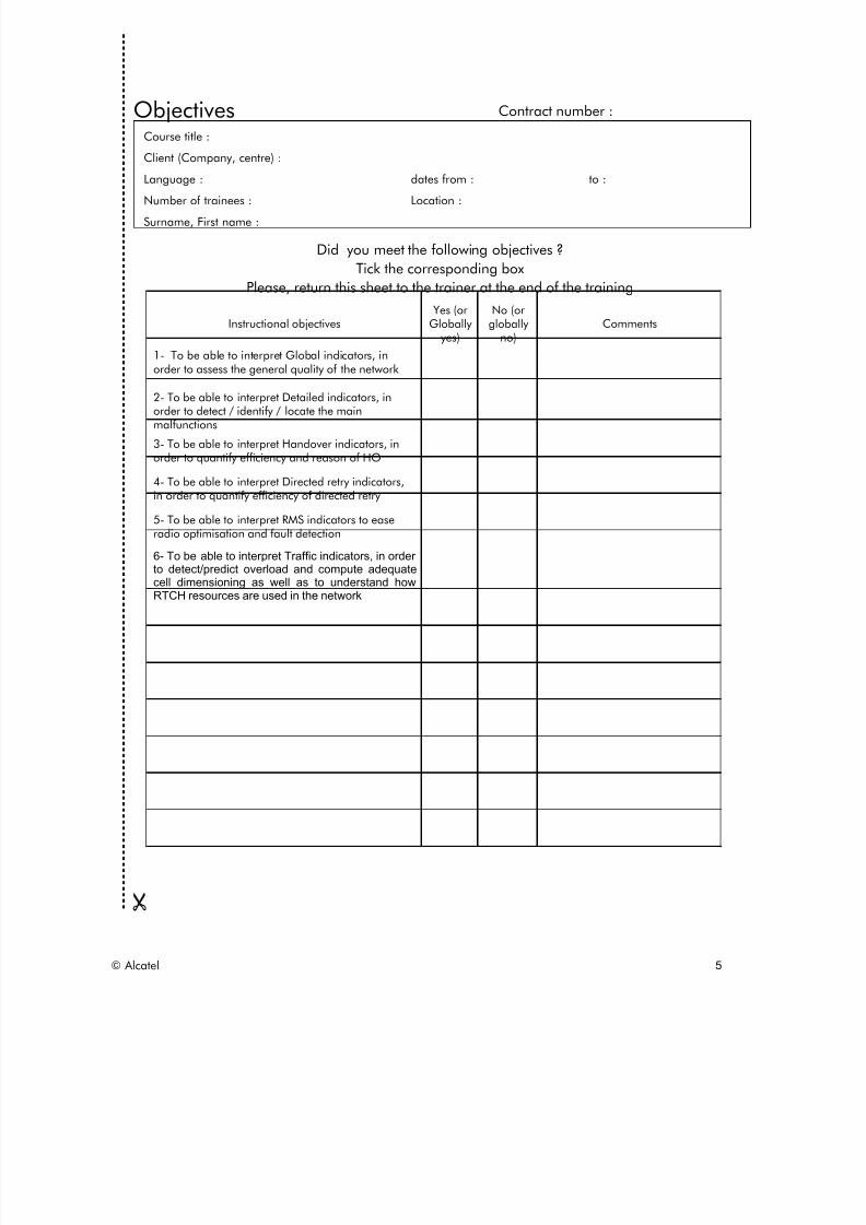
Objectives Contract number :
Course title :
Client (Company, centre) :
Language : dates from : to :
Number of trainees : Location :
Surname, First name :
Did you meet the following objectives ? Tick the corresponding box
Please, return this sheet to the trainer at the end of the training Instructional objectives
Yes (orGlobally
yes)
No (orglobally
no)Comments
1- To be able to interpret Global indicators, inorder to assess the general quality of the network
2- To be able to interpret Detailed indicators, inorder to detect / identify / locate the mainmalfunctions
3- To be able to interpret Handover indicators, inorder to quantify efficiency and reason of HO
4- To be able to interpret Directed retry indicators,in order to quantify efficiency of directed retry
5- To be able to interpret RMS indicators to easeradio optimisation and fault detection
6- To be able to interpret Traffic indicators, in orderto detect/predict overload and compute adequatecell dimensioning as well as to understand howRTCH resources are used in the network
© Alcatel 5

8/12/2019 QOS_B9 (Call Setup)
http://slidepdf.com/reader/full/qosb9-call-setup 6/388
Objectives (continued) Instructional objectives
Yes (or
Globallyyes)
No (or
globallyno) Comments
Other comments
Thank you for your answers to this questionnaire
© Alcatel 6

8/12/2019 QOS_B9 (Call Setup)
http://slidepdf.com/reader/full/qosb9-call-setup 7/388
All rights reserved © 2004, Alcatel
1 INTRODUCTION
© Alcatel 7

8/12/2019 QOS_B9 (Call Setup)
http://slidepdf.com/reader/full/qosb9-call-setup 8/388
8Introduction to Quality of the Service and Traffic Load MonitoringBSS Release B9
All rights reserved © 2004, Alcatel
1 IntroductionSection presentation
> Objective: to be able to explain what is QoS and Traffic Load
monitoring of the BSS and what are the information sourcesavailable for that purpose
> Program:
• 1.1 Monitoring the QoS of the BSS
• 1.2 Monitoring the Traffic Load of the BSS
• 1.3 Information sources available• 1.4 Introduction to K1205 PC emulation
© Alcatel 8

8/12/2019 QOS_B9 (Call Setup)
http://slidepdf.com/reader/full/qosb9-call-setup 9/388
All rights reserved © 2004, Alcatel
1 INTRODUCTION
1.1 Monitoring the QoS of the BSS
© Alcatel 9

8/12/2019 QOS_B9 (Call Setup)
http://slidepdf.com/reader/full/qosb9-call-setup 10/388
10Introduction to Quality of the Service and Traffic Load MonitoringBSS Release B9
All rights reserved © 2004, Alcatel
1.1 Monitoring the QoS of the BSSDefinition
> ”Monitor" "network" "quality"
• monitor = measure or ensure?
• network = BSS? BSS+NSS? BSS+NSS+PSTN …
• quality = service (end-user) and/or system (technical)
> But also detect, localize, diagnose outages
• detect (decide according to thresholds)
• localize (which cell, BSC, etc.)• diagnose: radio, BSS, TC problems
© Alcatel 10

8/12/2019 QOS_B9 (Call Setup)
http://slidepdf.com/reader/full/qosb9-call-setup 11/388
QoS Results
Managementnetwork monitoringcomparison with competitorcomparison of manufacturerscontractual requirement: licencequality responsible
Radio optimizationcell radio quality survey
HO quality monitoringassessment of tuning efficiency
BSS maintenancecell/BSC/TC problem detection
11Introduction to Quality of the Service and Traffic Load MonitoringBSS Release B9
All rights reserved © 2004, Alcatel
1.1 Monitoring the QoS of the BSSUsage
QoS Results
•••••
Management•network monitoring•comparison with competitor•comparison of manufacturers•contractual requirement: licence•quality responsible
•
••
Radio optimization•cell radio quality survey
•HO quality monitoring•assessment of tuning efficiency
•BSS maintenance•cell/BSC/TC problem detection
> 3 usages of QoS data ⇒3 levels of QoS reports:
1. Management team: has to compare Network QoS with competitors' one and to plan Network evolutions.
⇒needs to have a general view of the Network QoS on a monthly (and sometimes weekly)basis.
2. Radio Optimization team: has to detect bad QoS areas in the network and to implement andassess modifications for QoS improvement.
⇒needs to have a detailed status and evolution of the QoS at BSS and cell (and sometimesTRX) levels on a weekly, daily (and sometimes hourly) basis.
3. Supervision and Maintenance team: has to detect dramatic QoS degradations and identifythe responsible Network Element (and if possible component).
⇒needs to have the most detailed status of QoS at cell and TRX levels on an hourly basis.
© Alcatel 11

8/12/2019 QOS_B9 (Call Setup)
http://slidepdf.com/reader/full/qosb9-call-setup 12/388
All rights reserved © 2004, Alcatel
1 INTRODUCTION
1.2 Monitoring the Traffic Load of the BSS
© Alcatel 12

8/12/2019 QOS_B9 (Call Setup)
http://slidepdf.com/reader/full/qosb9-call-setup 13/388
13Introduction to Quality of the Service and Traffic Load MonitoringBSS Release B9
All rights reserved © 2004, Alcatel
1.2 Monitoring the Traffic Load of the BSSDefinition
> Measure the "quantity" of traffic handled by:
• the network
• the BSCs
• the cells
> Analyze traffic characteristics
• call, handover, location update, etc.
> As input for dimensioning/architecture team
> Traffic characteristics used as a "call mix" to dimension or re-dimension the network will bedeveloped in the section Monitoring the Traffic Load of the BSS.
© Alcatel 13

8/12/2019 QOS_B9 (Call Setup)
http://slidepdf.com/reader/full/qosb9-call-setup 14/388
All rights reserved © 2004, Alcatel
1 INTRODUCTION
1.3 Information sources available
© Alcatel 14

8/12/2019 QOS_B9 (Call Setup)
http://slidepdf.com/reader/full/qosb9-call-setup 15/388
15Introduction to Quality of the Service and Traffic Load MonitoringBSS Release B9
All rights reserved © 2004, Alcatel
1.3 Information sources availableObservation means
> DIFFERENT WAYS TO OBSERVE/MEASURE the GSM network
External Interface Analysis A interface: MSC/TC-BSC Abis interface: BSC/BTS Air MS/BTS
Counter browser
OMC CountersBSC(NSS)
Tektronix K1205
Gnnettest MPA W&G NPA
Abis
> QoS data can be built-up from different and complementary kinds of information sources.
> Usually post-processing applications will build up QoS indicators from:
• OMC-R counters provided by the BSS system itself.
• Signaling messages provided by a protocol acquisition tool on the different interfaceshandled by the BSS: Air, Abis, A (or Ater).
MSC/VLR
Air
A AbisBSC TC
BTS
Ater
SACCH RSL N7 N7
drive test tool protocol analyzer
MS
© Alcatel 15

8/12/2019 QOS_B9 (Call Setup)
http://slidepdf.com/reader/full/qosb9-call-setup 16/388
16Introduction to Quality of the Service and Traffic Load MonitoringBSS Release B9
All rights reserved © 2004, Alcatel
1.3 Information sources available A interface trace
INFORMATION SOURCE: EXTERNAL INTERFACE "A"
> Capture/decode signaling between MSC and BSC-TC (A or Ater MUX)
with "protocol analyzer" (Wandel, Tektronix, Gnnettest, etc.)
+ GSM standard, can be used for arbitrage between manufacturers
+ Complete information (message contents, time-stamp)
+ Possible detection of User/MS/BSS/TC/NSS problems
- High cost of equipment
- Time consuming, "post mortem" (installation of tool, file analysis)
- Expertise needed for analysis
- Low coverage (K1103/MA10: 8 COCs, K1205/MPA: 32 COCs maximum!)
- Large amount of data (>> 10 Mbytes /hour/BSC)
> The main advantage of the A interface is to allow the detection of Call Setup failures either due to the User or tothe NSS (or PSTN).
> Some typical user failure causes are: Some typical NSS failure causes are:
IMSI Unknown in VLR Temporary FailureIMSI Unknown in HLR Resource UnavailableIMEI Not Accepted Switching Equipment CongestionPLMN Not Allowed Normal UnspecifiedService Option Not Supported Recovery on Timer ExpiryRequested Service Not Supported Call RejectUnassigned Number InterworkingOperator Determined Barring Protocol ErrorUser Alerting Network Failure
Facility Not Subscribed CongestionNo Route to DestinationNormal Call ClearingUser BusyInvalid Number FormatCall RejectInterworkingNormal Unspecified
> CAUTION: In order to assess the QoS of a BSS or some cells of a BSS, all N7 links between this BSC and theMSC must be traced. Indeed, as the N7 signaling load is spread over all N7 links, signaling messages relating toone call can be conveyed on any of the active N7 links.
> K1103 protocol analyzer can trace up to 8 COCs at the same time but on maximum 4 PCM physical links.
> K1205 protocol analyzer can trace up to 32 COCs at the same time but on maximum 16 PCM physical links.
© Alcatel 16

8/12/2019 QOS_B9 (Call Setup)
http://slidepdf.com/reader/full/qosb9-call-setup 17/388
17Introduction to Quality of the Service and Traffic Load MonitoringBSS Release B9
All rights reserved © 2004, Alcatel
1.3 Information sources availableExample of trace
On a K1205 protocol analyzer
© Alcatel 17
8/12/2019 QOS_B9 (Call Setup)
http://slidepdf.com/reader/full/qosb9-call-setup 18/388
18Introduction to Quality of the Service and Traffic Load MonitoringBSS Release B9
All rights reserved © 2004, Alcatel
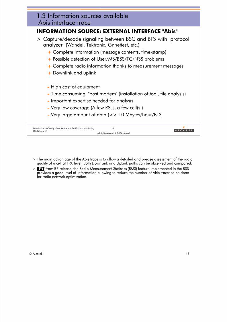
1.3 Information sources available Abis interface trace
INFORMATION SOURCE: EXTERNAL INTERFACE "Abis"
> Capture/decode signaling between BSC and BTS with "protocol
analyzer" ( Wandel, Tektronix, Gnnettest, etc.)+ Complete information (message contents, time-stamp)
+ Possible detection of User/MS/BSS/TC/NSS problems
+ Complete radio information thanks to measurement messages
+ Downlink and uplink
- High cost of equipment
- Time consuming, "post mortem" (installation of tool, file analysis)
- Important expertise needed for analysis
- Very low coverage (A few RSLs, a few cell(s))
- Very large amount of data (>> 10 Mbytes/hour/BTS)
> The main advantage of the Abis trace is to allow a detailed and precise assessment of the radioquality of a cell at TRX level. Both DownLink and UpLink paths can be observed and compared.
> BUT from B7 release, the Radio Measurement Statistics (RMS) feature implemented in the BSSprovides a good level of information allowing to reduce the number of Abis traces to be donefor radio network optimization.
© Alcatel 18

8/12/2019 QOS_B9 (Call Setup)
http://slidepdf.com/reader/full/qosb9-call-setup 19/388
19Introduction to Quality of the Service and Traffic Load MonitoringBSS Release B9
All rights reserved © 2004, Alcatel
1.3 Information sources available Air interface trace
INFORMATION SOURCE: EXTERNAL INTERFACE "Air"
> Use trace MS to capture signaling and signal characteristics
+ Give precise location (x,y) of problems+ Give downlink radio information
+ Only way to localize a lack of coverage
+ Only way to monitor competitor
- High cost of equipment
- Very time-consuming
- Difficulty to perform a lot of calls-> number of samples insufficient
-> only a few streets
- No uplink
> The main advantage of the Air trace is to associate a radio quality measurement to a givengeographical area of the network.
> Even if the RMS feature will allow to assess the radio quality as perceived by the end user, nolocation of the radio problems is provided through the RMS.
© Alcatel 19

8/12/2019 QOS_B9 (Call Setup)
http://slidepdf.com/reader/full/qosb9-call-setup 20/388
20Introduction to Quality of the Service and Traffic Load MonitoringBSS Release B9
All rights reserved © 2004, Alcatel
1.3 Information sources availablePerformance Measurement counters
SUB-SYSTEM COUNTERS
> Counts events seen by sub-system, value reported periodically
(1 hour)
+ Low cost: collected directly at OMC
+ Compact data: possibility to store counters for a complete network
- Raw information, having to be consolidated to be understandable
- Manufacturer's dependent: questionable/difficult to compare- Weak to analyze other sub-systems
> The main advantage of the BSS counters is to provide easily QoS data for permanent QoSmonitoring.
© Alcatel 20

8/12/2019 QOS_B9 (Call Setup)
http://slidepdf.com/reader/full/qosb9-call-setup 21/388
21Introduction to Quality of the Service and Traffic Load MonitoringBSS Release B9
All rights reserved © 2004, Alcatel
1.3 Information sources availableExercise
> Draw the BSS PM counters flow on the chart
> In which sub-system are the BSS QoS indicators
computed and stored?
BSC
BSC
BSC
OMC-R
OMC-R OMC-R
NPA
RNO
© Alcatel 21

8/12/2019 QOS_B9 (Call Setup)
http://slidepdf.com/reader/full/qosb9-call-setup 22/388
22Introduction to Quality of the Service and Traffic Load MonitoringBSS Release B9
All rights reserved © 2004, Alcatel
1.3 Information sources availableBSS counters
BSS COUNTERS
> Combined into significant formulae: indicators
> Used to monitor BSS network quality
> Over a complete network, with breakdown per cell/BSC
> SPECIFIC DRAWBACK
• NSS/PSTN/MS/USER problems not seen
> As BSS PM counters are defined in order to provide information to assess the QoS of the BSSand help to detect BSS misbehavior, there is no way to identify QoS problems due to NSS,PSTN or User.
© Alcatel 22

8/12/2019 QOS_B9 (Call Setup)
http://slidepdf.com/reader/full/qosb9-call-setup 23/388
23Introduction to Quality of the Service and Traffic Load MonitoringBSS Release B9
All rights reserved © 2004, Alcatel
1.3 Information sources availableNSS counters
NSS COUNTERS
> Combined into significant formulas: indicators
> Used to monitor NSS network quality
> Over a complete network, with breakdown per BSC (maximum)
> SPECIFIC DRAWBACKS
• BSS problems usually not precisely identified
• No breakdown per cell
> The NSS QoS is provided through NSS PM counters and indicators. It is out of the scope ot thistraining course.
© Alcatel 23
8/12/2019 QOS_B9 (Call Setup)
http://slidepdf.com/reader/full/qosb9-call-setup 24/388
24Introduction to Quality of the Service and Traffic Load MonitoringBSS Release B9
All rights reserved © 2004, Alcatel
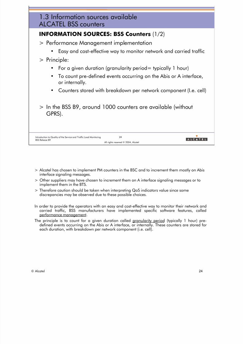
1.3 Information sources available ALCATEL BSS counters
INFORMATION SOURCES: BSS Counters (1/2)
> Performance Management implementation
• Easy and cost-effective way to monitor network and carried traffic
> Principle:
• For a given duration (granularity period= typically 1 hour)
• To count pre-defined events occurring on the Abis or A interface,or internally.
• Counters stored with breakdown per network component (I.e. cell)
> In the BSS B9, around 1000 counters are available (withoutGPRS).
> Alcatel has chosen to implement PM counters in the BSC and to increment them mostly on Abisinterface signaling messages.
> Other suppliers may have chosen to increment them on A interface signaling messages or toimplement them in the BTS.
> Therefore caution should be taken when interpreting QoS indicators value since somediscrepancies may be observed due to these possible choices.
In order to provide the operators with an easy and cost-effective way to monitor their network andcarried traffic, BSS manufacturers have implemented specific software features, calledperformance management.
The principle is to count for a given duration called granularity period (typically 1 hour) predefined events occurring on the Abis or A interface, or internally. These counters are stored foreach duration, with breakdown per network component (i.e. cell).
© Alcatel 24

8/12/2019 QOS_B9 (Call Setup)
http://slidepdf.com/reader/full/qosb9-call-setup 25/388
25Introduction to Quality of the Service and Traffic Load MonitoringBSS Release B9
All rights reserved © 2004, Alcatel
1.3 Information sources available ALCATEL BSS counters
INFORMATION SOURCES: BSS Counters (2/2)
> In Alcatel BSS (except GPRS), counters are computed by BSC,
based mainly on Abis messages.
> Every reporting period, counters values are sent to the OMC-Rfor storage.
> Several counters are reported to the OMC-R permanently everyPM granularity period:
• Type 180: per cell adjacency
• Type 110 per cell
• Other Types: per TRX / N7 Link / BSC …/…
Millions of counters are collected every day
© Alcatel 25

8/12/2019 QOS_B9 (Call Setup)
http://slidepdf.com/reader/full/qosb9-call-setup 26/388
26Introduction to Quality of the Service and Traffic Load MonitoringBSS Release B9
All rights reserved © 2004, Alcatel
1.3 Information sources availableBSS counter Example
> MC718:
counter number
> NB_TCH_NOR_ASS_SUCC_TRX: counter name> Cumulative: method of computation
> Type 110: BSS PM measurement type to which the counter belongs
> Measured object: minimum object level for which the counter isprovided: TRX or CELL or BSC or N7 LINK or X25 LINK etc.
> All counters are described in the "PM counters and indicators".
© Alcatel 26
8/12/2019 QOS_B9 (Call Setup)
http://slidepdf.com/reader/full/qosb9-call-setup 27/388
27Introduction to Quality of the Service and Traffic Load MonitoringBSS Release B9
All rights reserved © 2004, Alcatel
1.3 Information sources availableBSS counter characteristics
Collection mechanism
> Cumulative• The counter is incremented at the occurrence of a specific event
• Abis or A message, or internal event
• At the end of a collection period, the result is the sum of the events
> Inspection
• Every 20 or 10 seconds, a task quantifies an internal resource status(usually a table)
• At the end of a collection period, the result is the mean value
> Observation
• Set of recorded information about a telecom procedure (handover,channel release, UL & DL measurements reporting)
> Main counters are of cumulative type.
> Inspection counters are of gauge type.
> Observation counters are grouped in a Performance Measurement record associated to aparticular GSM BSS telecom procedure: SDCCH channel seizure, TCH channel seizure, internalhandover, etc.
© Alcatel 27

8/12/2019 QOS_B9 (Call Setup)
http://slidepdf.com/reader/full/qosb9-call-setup 28/388
28Introduction to Quality of the Service and Traffic Load MonitoringBSS Release B9
All rights reserved © 2004, Alcatel
1.3 Information sources availableBSS Performance Measurement types
N° Type Name Type definition
1 Traffic Measurement Set of counters related to the traffic evaluation per telecom procedure
2 Resource Availability Measurement Set of counters related to the availability of the CCCH, SDCCH, or TCH channels
3 CCCH channel resource usage measurements Set of counters related to the usage of CCCH channel (PCH, AGCH, RACH)
4 SDCCH channel resource usage measurements Set of counters related to the usage of SDCCH channel
5 TCH channel resource usage measurements Set of counters related to the usage of TCH channel6 TCH Handover Measurements Set of counters related to the TCH handover procedure
7 LAPD Measurement Set of counters related to the LapD logical links
8 X.25 Measurement Set of counters related to the X25 links OMC-BSC
9 N7 Measurement Set of counters related to the N7 Signaling Links
10 SDCCH Observations Observation counters on SDCCH channels allocated
11 TCH measurements observations Observation counters on 08.58 MEASUREMENT REPORT for a TCH
12 Internal Handover Observations Observation counters on internal intra-cell or inter-cell SDCCH or TCH handover
13 Incoming External Handover Observations Observation counters on incoming external SDCCH or TCH handover
14 Outgoing External Handover Observations Observation counters on outgoing external SDCCH or TCH handover
15 TCH Observation Observation counters on TCH channel allocated
18 A Interface measurements different causes of 08.08 CLEAR REQUEST and 08.08 ASSIGNMENT FAILURE
19 SMS PP Measurements Set of counters related to Short Message Service Point to Point
25 SCCP Measurements Set of counters related to SCCP Layer of the N7 signaling Links
26 TCH outgoing Handover per adjency Set of counters related to outgoing TCH handover provided per adjency
27 TCH incoming Handover per adjency Set of counters related to incoming TCH handover provided per adjency
28 SDCCH Handover Set of counter related to the SDCCH handover procedure
29 Directed Retry measurements Set of counter related to the directed retry handover procedure
30 SMS CB Measurements Set of counters related to Short Message Service Cell Broadcast
31 Radio Measurement Statistics Set of counters providing radio quality measurements for TRX/Cell
32 Change of frequency band measurements Set of counters related to handovers including a change of TCH Frequency band
33 BTS Power Measurement Average emitted power at the BTS antenna output
110 Overview measurements Set of key counters allowing to access Quality of Service of a given Cell/BSC/Network
180 Traffic Flow measurements Set of counters related to incoming inter-cell SDCCH/TCH handover performed per adjency
B9
NewB9
ANNEX 6
> BSS Performance Measurement types (PM types) are split into two categories:
• standard types (7, 8, 9, 18, 19, 25, 28, 29, 30, 31, 32,110, 180)
• detailed types (1, 2, 3, 4, 5, 6, 10, 11, 12, 13, 14, 15, 26, 27)
> The most important types for QoS monitoring and Radio Network Optimization are in bold.
> A standard PM type can be activated for the whole network. It means that the related counters are reported for allthe Network Elements they are implemented on (TRX, CELL, N7 link, X25 link, LAPD link, Adjacency).
> A detailed PM type can be activated only on a sub-set of the network. It means that the related counters arereported only for a limited number of Network Elements:
• 40 cells per BSS for PM types 1, 2, 3, 4, 5, 6, 26, 29
• 15 cells per BSS for PM types 10, 12, 13, 14, 15
• 1 cell per BSS for PM types 11, 27
> Counter numbering rules:
• Cyz: cumulative or inspection counters in PM types 1, 2, 3, 4, 5, 6, 18, 19, 25, 26, 27, 28, 29, 30, 32,180
• Ly.z: cumulative counters in PM type 7 (L stands for LAPD link)
• Xy.z: cumulative counters in PM type 8 (X stands for X25 link)
• Ny.z: cumulative counters in PM type 9 (N stands for N7 link)
• Syz: observation counters in PM type 10 (S stands for SDCCH)
• Ryz:: observation counters in PM type 11 (R stands for Radio measurements)
• HOyz: observation counters in PM type 12, 13, 14 (HO stands for HandOver)
•
Tyz: observation counters in PM type 15 (T stands for TCH)• RMSyz: cumulative counters in PM type 31 (RMS stands for Radio Measurement Statistics)
• MCyz or MNy.z: cumulative counters in PM type 110 (M stands for Major)
© Alcatel 28

8/12/2019 QOS_B9 (Call Setup)
http://slidepdf.com/reader/full/qosb9-call-setup 29/388
29Introduction to Quality of the Service and Traffic Load MonitoringBSS Release B9
All rights reserved © 2004, Alcatel
1.3 Information sources availableObservation means
Training exercise: find the best source of informationObservation to be done : Best source Why
6- history of network quality for several
weeks
8- discriminate problems between BSS/NSS.BSS and NSS coming from different
providers
9- In a building, one is thinking that an
elevator is inducing PCM trouble, how to
confirm ?
10- Identify potential interfering cells of 1
Cells
5- localise abnormal cells in a network
7- compare networks quality
3- get average network quality
4- localise precise location of a radio pb
1- overall radio quality of 1 cell Counters Type 31: RMS
2- monitor user failures
© Alcatel 29

8/12/2019 QOS_B9 (Call Setup)
http://slidepdf.com/reader/full/qosb9-call-setup 30/388
All rights reserved © 2004, Alcatel
1 INTRODUCTION
1.4 Introduction to K1205 PC emulation
© Alcatel 30

8/12/2019 QOS_B9 (Call Setup)
http://slidepdf.com/reader/full/qosb9-call-setup 31/388
31Introduction to Quality of the Service and Traffic Load MonitoringBSS Release B9
All rights reserved © 2004, Alcatel
1.4 Introduction to K1205 PC emulationUsage
INTRODUCTION TO K1205 PC EMULATION
> The trace done with K1205 can be read:
• Directly on K1205 itself
• On any PC Windows NT with dedicated emulation software
> Practical exercises will be done during the course using thissoftware
> The following slides and exercises are here to teach you thebasic skill needed to operate the tool for A Interface decoding
© Alcatel 31

8/12/2019 QOS_B9 (Call Setup)
http://slidepdf.com/reader/full/qosb9-call-setup 32/388
To select binarytrace file
To enter in monitoringmode to analyze the
A trace
To filter the mainGSM protocolsand messages
32Introduction to Quality of the Service and Traffic Load MonitoringBSS Release B9
All rights reserved © 2004, Alcatel
1.4 Introduction to K1205 PC emulationMeasurement Scenarios screen
To select binarytrace file
To enter in monitoringmode to analyze the
A trace
To filter the mainGSM protocolsand messages
1. Start the K1205 Protocol Tester application.
2. In the Recording File box: click on the Open button and select the "PAIB29.rec" file.
3. Select all displayed N7 logical links (corresponding to 4 PCMs in this case).
4. Click on the Browse button and select gsm2_A.stk in the gsm2 sub-directory (corresponding tothe GSM Phase 2 A interface protocol stack).
5. Click on OK.6. Click on the Monitor box to display the content of the recorded trace.
© Alcatel 32

8/12/2019 QOS_B9 (Call Setup)
http://slidepdf.com/reader/full/qosb9-call-setup 33/388
33Introduction to Quality of the Service and Traffic Load MonitoringBSS Release B9
All rights reserved © 2004, Alcatel
1.4 Introduction to K1205 PC emulationFilter configuration
> Configure your filter to remove some messagesand protocols => Bypass Protocol Filter
and select:
- SCCP Except UDT
- Keep all DTAP
- BSSM Except PAGIN
Select also allLogical Links
ANNEX 4
> The ANNEX 4 introduces some basics on the GSM protocol layers that will be traced for the A interface analysis.> UDT: Unit Data (for Signaling Control Point) Remove Paging information
© Alcatel 33

8/12/2019 QOS_B9 (Call Setup)
http://slidepdf.com/reader/full/qosb9-call-setup 34/388
Short View1 line mess
Frame ViewFull decoding of
selected message
Packet viewMessage contentin hexadecimal
To extract 1 call
34Introduction to Quality of the Service and Traffic Load MonitoringBSS Release B9
All rights reserved © 2004, Alcatel
1.4 Introduction to K1205 PC emulationMonitor screen
/ age
Short View1 line / message
Frame ViewFull decoding of
selected message
Packet viewMessage contentin hexadecimal
To extract 1 call
© Alcatel 34

8/12/2019 QOS_B9 (Call Setup)
http://slidepdf.com/reader/full/qosb9-call-setup 35/388
35Introduction to Quality of the Service and Traffic Load MonitoringBSS Release B9
All rights reserved © 2004, Alcatel
1.4 Introduction to K1205 PC emulationExtract a Call
> How to Find a specific message?
• Edit -> Find (or ctrl + F3)
– Select All Logical Links– Chose the protocol
– Select the message studied
• Use F3 to find another same message
> How to Extract a call on these trace?
• Click on Zoom button
• Select CC message (Connection Confirm)
• And UnZoom + Zoom to get:
– SLR: Source Location ReferenceDLR: Destination Location Reference
> At call setup, the first signaling message on the A interface is sent by the BSC to the MSC in order to set up a logical link (calledSCCP connection) between the BSS and the NSS.
> Both BSS and NSS entities choose a unique reference which has to be used by the other party to identify the SCCP connectionon which the messages are conveyed. Both BSS reference ( xxx ) and NSS reference ( yyy ) are exchanged during the SCCPConnection Request and Connection Confirm phases. After that only the reference of the other party is used.
BSC MSC
Radio Link Establishment
SCCP CR SLR= xxx ; DLR= none
SCCP CC SLR= yyy ; DLR= xxx
msg i
SLR= none ; DLR= yyy
msg j
SLR= none ; DLR= xxx
© Alcatel 35

8/12/2019 QOS_B9 (Call Setup)
http://slidepdf.com/reader/full/qosb9-call-setup 36/388
36Introduction to Quality of the Service and Traffic Load MonitoringBSS Release B9
All rights reserved © 2004, Alcatel
1.4 Introduction to K1205 PC emulationCall extraction
Then
> Click on the Filter button and filter out all protocol layers and messages except:
• all DTAP messages,
• all BSSMAP messages except "Paging”,
• SCCP CR (Connection Request) and CC (Connection Confirm) messages.
© Alcatel 36

8/12/2019 QOS_B9 (Call Setup)
http://slidepdf.com/reader/full/qosb9-call-setup 37/388
37Introduction to Quality of the Service and Traffic Load MonitoringBSS Release B9
All rights reserved © 2004, Alcatel
1.4 Introduction to K1205 PC emulationExercise
PRACTICAL EXERCICE
> Use the tool to extract a few calls from file
PAIB29.REC1) Zoom on a CC message:
Find the definition of all messages in theFrame View?
2) Zoom on a CR message with LUREQ
How to extract the complete call?
3) Use “Find” to extract a call with a ALERTINGmessage.Can you see the CC message? If not, Why?
© Alcatel 37

8/12/2019 QOS_B9 (Call Setup)
http://slidepdf.com/reader/full/qosb9-call-setup 38/388
All rights reserved © 2004, Alcatel
2 GLOBAL INDICATORS
© Alcatel 38

8/12/2019 QOS_B9 (Call Setup)
http://slidepdf.com/reader/full/qosb9-call-setup 39/388
39Introduction to Quality of the Service and Traffic Load MonitoringBSS Release B9
All rights reserved © 2004, Alcatel
2 Global indicatorsSection presentation
> Objective: to be able to explain what is a Global indicator and
what are the main BSS indicators regarding GSM servicesprovided by the Alcatel BSS
> Program:
• 2.1 Indicators definition
• 2.2 Methodological precautions
• 2.3 Typical call failures• 2.4 Description of global indicators
• 2.5 Traps and restrictions of global indicators
• 2.6 Global indicators interpretation
© Alcatel 39

8/12/2019 QOS_B9 (Call Setup)
http://slidepdf.com/reader/full/qosb9-call-setup 40/388
All rights reserved © 2004, Alcatel
2 GLOBAL INDICATORS
2.1 Indicators definition
© Alcatel 40
8/12/2019 QOS_B9 (Call Setup)
http://slidepdf.com/reader/full/qosb9-call-setup 41/388
41Introduction to Quality of the Service and Traffic Load MonitoringBSS Release B9
All rights reserved © 2004, Alcatel
2.1 Indicators definitionGlobal / detailed
BSS INDICATORS DEFINITION (Alcatel)
> Numerical data providing information about networkperformance regarding:
• The complete network: GLOBAL indicator
• An element of the network: DETAILED indicator
– TS/TRX/CELL/BTS/BSC/TC
> A formulae of several counter(s)
> Counters vs. Indicators• Counters: provided by the BSS equipments
• Indicators: computed by BSS Monitoring equipments
> The indicators computation can be performed from several counters or by a simple countermapping.
> Example:
• call drop rate = Call Drop nb / Call nb = f(counters)
• call drop = Call drop nb = 1 counter
© Alcatel 41
8/12/2019 QOS_B9 (Call Setup)
http://slidepdf.com/reader/full/qosb9-call-setup 42/388
42Introduction to Quality of the Service and Traffic Load MonitoringBSS Release B9
All rights reserved © 2004, Alcatel
2.1 Indicators definitionGlobal
GLOBAL INDICATORS
> Measure the performance of the complete network
> Analyzed according their trend and values
• Usually every day (week, month)
> Compared with:
• Competitor results if available
• Contractual requirements
• Internal quality requirements
© Alcatel 42

8/12/2019 QOS_B9 (Call Setup)
http://slidepdf.com/reader/full/qosb9-call-setup 43/388
Weekly CDR GSM
0,00
0,50
1,00
1,50
2,00
2,50
3,00
3,50
5 9 3 7 5 9 33 37 4 45
week number
R weekly call drop rate
contractual call drop rate
quality CDR
43Introduction to Quality of the Service and Traffic Load MonitoringBSS Release B9
All rights reserved © 2004, Alcatel
2.1 Indicators definitionThresholds
EXAMPLE: Thresholds on Call Drop Rate indicator
Weekly CDR "GSM"
0,00%0,50%
1,00%
1,50%
2,00%
2,50%
3,00%
3,50%
1 5 9 1 3
1 7
2 1
2 5
2 9
3 3
3 7
4 1
4 5
week number
C D R
weekly call drop rate
contractual call drop rate
quality CDR
> The Call Drop rate at network level has to compared to:
• Contractual threshold: can be requested by the operator management to the operationalradio team, can be requested by the operator to the provider on swap or networkinstallation
• Quality threshold: fixed internally by radio team management.
> Quality thresholds are usually more tight than contractual ones.
© Alcatel 43

8/12/2019 QOS_B9 (Call Setup)
http://slidepdf.com/reader/full/qosb9-call-setup 44/388
INDICATOR DESCRIPTION G ?
a ve ra ge of ca ll se tup succe ss ra te for the ne tw ork Y
ra te of ca ll lost due to ra dio pb on ce ll CI=14, LAC=234 No
cal l drop rate in your capital
cal l drop rate of the cel l covering a specific buidl ing
of HO w ith the cause better ce l l (among other causes) for the network
average rate o f TCH dropped for a l l TRX of the netw ork carry ing 1 SDCCH8
rate of SDCCH dropped on TRX1 of cel l 12,24
call success of 1 PLM N
of ce lls be i co sted toda
44Introduction to Quality of the Service and Traffic Load MonitoringBSS Release B9
All rights reserved © 2004, Alcatel
2.1 Indicators definitionExercise
> TRAINING EXERCISE: GLOBAL OR NOT
es
ng nge y
INDICATOR DESCRIPTION G ?
average of call setup success rate for the network Yes
rate of call lost due to radio pb on cell CI=14, LAC=234 No
call drop rate in your capital
call drop rate of the cell covering a specific buidling
% of HO with the cause better cell (among other causes) for the network
average rate of TCH dropped for all TRX of the network carrying 1 SDCCH8
rate of SDCCH dropped on TRX1 of cell 12,24
call success of 1 PLMN% of cells being congested today
© Alcatel 44

8/12/2019 QOS_B9 (Call Setup)
http://slidepdf.com/reader/full/qosb9-call-setup 45/388
All rights reserved © 2004, Alcatel
2 GLOBAL INDICATORS
2.2 Methodological precautions
© Alcatel 45

8/12/2019 QOS_B9 (Call Setup)
http://slidepdf.com/reader/full/qosb9-call-setup 46/388
46Introduction to Quality of the Service and Traffic Load MonitoringBSS Release B9
All rights reserved © 2004, Alcatel
2.2 Methodological precautionsObjective
METHODOLOGICAL PRECAUTIONS
> Avoid typical errors regarding indicators interpretation
© Alcatel 46
8/12/2019 QOS_B9 (Call Setup)
http://slidepdf.com/reader/full/qosb9-call-setup 47/388
47Introduction to Quality of the Service and Traffic Load MonitoringBSS Release B9
All rights reserved © 2004, Alcatel
2.2 Methodological precautionsGlobal indicator value
A good value for a global indicator
All network components are OK regarding this indicator
> Example
• A global call drop rate of 1%
• Can hide some cells with 10 % of call drop rate
© Alcatel 47

8/12/2019 QOS_B9 (Call Setup)
http://slidepdf.com/reader/full/qosb9-call-setup 48/388
2.2 Methodological precautionsNetwork Element aggregation
> The average value of an indicator for a Network
• Is not the average of cell results (or any sub-part of it)
• BUT the average weighted by the traffic
number of calls number of call drop call drop rate
cell 1 390 8 2,10%
cell 2 546 29 5,25%
cell 3 637 20 3,10%
cell 4 1029 12 1,14%
cell 5 536 3 0,50%
cell 6 2 1 50,00%
cell 7 3 1 33,00%
cell 8 210 4 2,11%
cell 9 432 5 1,20%
cell 10 321 4 1,11%
average of cell results 9,95%
total nb of drop/total number of calls 2,10%
48Introduction to Quality of the Service and Traffic Load MonitoringBSS Release B9
All rights reserved © 2004, Alcatel
© Alcatel 48
8/12/2019 QOS_B9 (Call Setup)
http://slidepdf.com/reader/full/qosb9-call-setup 49/388
49Introduction to Quality of the Service and Traffic Load MonitoringBSS Release B9
All rights reserved © 2004, Alcatel
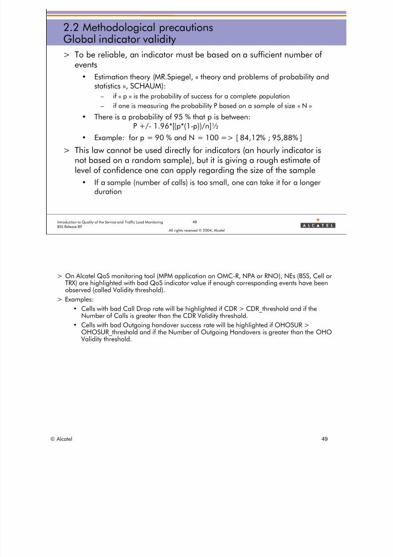
2.2 Methodological precautionsGlobal indicator validity
> To be reliable, an indicator must be based on a sufficient number ofevents
• Estimation theory (MR.Spiegel, « theory and problems of probability andstatistics », SCHAUM):
– if « p » is the probability of success for a complete population
– if one is measuring the probability P based on a sample of size « N »
• There is a probability of 95 % that p is between:P +/- 1.96*[(p*(1-p))/n]½
• Example: for p = 90 % and N = 100 => [ 84,12% ; 95,88% ]
> This law cannot be used directly for indicators (an hourly indicator is
not based on a random sample), but it is giving a rough estimate oflevel of confidence one can apply regarding the size of the sample
• If a sample (number of calls) is too small, one can take it for a longerduration
> On Alcatel QoS monitoring tool (MPM application on OMC-R, NPA or RNO), NEs (BSS, Cell orTRX) are highlighted with bad QoS indicator value if enough corresponding events have beenobserved (called Validity threshold).
> Examples:
• Cells with bad Call Drop rate will be highlighted if CDR > CDR_threshold and if theNumber of Calls is greater than the CDR Validity threshold.
• Cells with bad Outgoing handover success rate will be highlighted if OHOSUR >OHOSUR_threshold and if the Number of Outgoing Handovers is greater than the OHO Validity threshold.
© Alcatel 49

8/12/2019 QOS_B9 (Call Setup)
http://slidepdf.com/reader/full/qosb9-call-setup 50/388
50Introduction to Quality of the Service and Traffic Load MonitoringBSS Release B9
All rights reserved © 2004, Alcatel
2.2 Methodological precautionsTime period aggregation
> Take care of data consolidation
> Example:
Mean cell congestion rate during busy hour:
• Weighted average of cell congestion at the busy hour of thenetwork?
• Weighted average of cell congestion rate for its specific busy
hour?• (definition of busy hour?)
> Usually:
• Cell Busy Hour = hour of the day where max TCH traffic (in erlang) is observed.
• BSC Busy Hour = hour of the day where max TCH traffic (as the sum of the TCH traffic ofall cells of the BSS) is observed.
© Alcatel 50

8/12/2019 QOS_B9 (Call Setup)
http://slidepdf.com/reader/full/qosb9-call-setup 51/388
51Introduction to Quality of the Service and Traffic Load MonitoringBSS Release B9
All rights reserved © 2004, Alcatel
2.2 Methodological precautionsExercise
METHODOLOGICAL PRECAUTION: Training exercise
INDICATOR Sample(calls)
conclusion OK ?
call drop = 0.9% in your country 2456435 all the cells have a good call drop NOK
call setup success for cell 15, 145 = 99,5% 2315 there is a good call setup success rate for
15,145In Paris : 2500 cells with 95% of call setupsuccessIn the rest of France : 5000 cells with98%
3267872for France
In France, call setup success = 97 %
call drop for BSS « BSS_1 » = 1% 4500 the call drop for BSS_1 is good
call drop for cell 156;13 = 5% 215 cell 156;13 has certainly a trouble
for BSS 1, call drop of 2,0%
for BSS 2, call drop of 3,0%
4000
2000
LA = BSS1 + BSS2 has a call drop of 2,3 %
MSC « Stadium » has a call setup success of95 %
15346 BSS1 belonging to MSC Stadium has a call setupsuccess of 95¨%
© Alcatel 51
8/12/2019 QOS_B9 (Call Setup)
http://slidepdf.com/reader/full/qosb9-call-setup 52/388
All rights reserved © 2004, Alcatel
2 GLOBAL INDICATORS
2.3 Typical call failures
© Alcatel 52

8/12/2019 QOS_B9 (Call Setup)
http://slidepdf.com/reader/full/qosb9-call-setup 53/388
53Introduction to Quality of the Service and Traffic Load MonitoringBSS Release B9
All rights reserved © 2004, Alcatel
2.3 Typical call failuresObjective
> Description of the main call success and failures cases, with
• Main specific counters
• Main protocol timers
> Diagnose the main case of failures on A interface traces usingK1205 emulation software
© Alcatel 53

8/12/2019 QOS_B9 (Call Setup)
http://slidepdf.com/reader/full/qosb9-call-setup 54/388
54Introduction to Quality of the Service and Traffic Load MonitoringBSS Release B9
All rights reserved © 2004, Alcatel
2.3 Typical call failuresCall Setup phasing
> 4 stages for a call establishment, 2 for a location update:
1- Radio link establishment
2- "SDCCH phase“
then only for "Circuit Switch call"
3- TCH assignment
4- " Alerting/connection" phase
> Each phase has a specific utility and weaknesses
Radio Link EstablishmentSDCCH PhaseTCH assignment
Alerting/CNX Phase
© Alcatel 54

8/12/2019 QOS_B9 (Call Setup)
http://slidepdf.com/reader/full/qosb9-call-setup 55/388
55Introduction to Quality of the Service and Traffic Load MonitoringBSS Release B9
All rights reserved © 2004, Alcatel
2.3 Typical call failuresRadio Link Establishment - OC success
Originated Call: RLE success case
• T3101: guard timer for SDCCH allocation (Default: 3 seconds)• CR/CC are used to exchange SCCP references
– Any further message related to this call will have one (or 2) of these2 references
– K1205 can extract the call using these references (SLR, DLR!!)
MS BTS BSCMSC
CHANNEL REQUEST-------------(RACH)------------> CHANNEL REQUIRED
----------------------------------------------> MC8CCHANNEL ACTIVATION (SDCCH)
<--------------------------------------------- MC148CHANNEL ACTIVATION ACK
---------------------------------------------->IMMEDIATE ASSIGN COMMAND
IMMEDIATE ASSIGN <--------------------------------------------- start T3101
MC8B<------------(AGCH)------------
SABM (L3 info)-------------(SDCCH)-----------> ESTABLISH IND (L3 info)
UA (L3 info) ----------------------------------------------> stop T3101<-----------(SDCCH)------------ MC02
CR (COMPLETE L3 INFO)---------------------------------->
CC
<---------------------------------
Specific case of Call establishmentfailure:Loss of messages due to LapD congestioncan be follow with a counter (see notes)LapD
Radio Link EstablishmentSDCCH PhaseTCH assignment Alerting/CNX Phase
> The SDCCH resource allocation is performed by the BSC. Once allocated the SDCCH channel is activated by theBTS on BSC request.
> T3101 is the guard timer for the SDCCH access from the MS. The Default value is 3 seconds.
> MC8C counts the number of Channels Required received from the MS in a cell.
> MC148 counts the number of SDCCH channels activated (therefore allocated) in a cell.
> MC8B counts the number of time an MS is commanded to access an SDCCH channel in a cell.
> MC02 counts the number of MSs which have successfully accessed an SDCCH in a cell as part of a MobileOriginating (MO) call.
> The SCCP Connection Request message is conveyed on an A interface PCM timeslot chosen by the BSC (calledCOC).
> The SCCP Connection Confirm message is conveyed on a COC chosen by the MSC which can be located on adifferent PCM than the one of the COC used by the BSC to send signaling messages to the MSC.
> Take care than, when the BSC is congested on the downlink, some messages are discarded. This may result forexample in call establishment failures, loss of paging messages or delay in handover procedures.
> A LapD counter that indicates the time a LapD link is congested is created to analyze the cause of a degradedquality of service. This counter is implemented in type 7 and thus only be available in a detailed measurementcampaign.
• Counter: L1.18: TIME_LAPD_CONG
• Definition: Time in seconds during which the LapD link is congested in transmission in the BSC.
© Alcatel 55

8/12/2019 QOS_B9 (Call Setup)
http://slidepdf.com/reader/full/qosb9-call-setup 56/388
56Introduction to Quality of the Service and Traffic Load MonitoringBSS Release B9
All rights reserved © 2004, Alcatel
2.3 Typical call failuresRadio Link Establishment - TC success
Terminated Call: RLE success caseMS BTS BSC MSC
PAGINGPAGING COMMAND <---------------------------------
PAGING REQUEST <--------------------------------------------- start T 3113<------------- (PCH)------------- MC8A
CHANNEL REQUEST------------- (RACH)------------> CHANNEL REQUIRED
----------------------------------------------> MC8CCHANNEL ACTIVATION (SDCCH)
<--------------------------------------------- MC148CHANNEL ACTIVATION ACK
---------------------------------------------->IMMEDIATE ASSIGN COMMAND
IMMEDIATE ASSIGN <--------------------------------------------- Start T3101<------------ (AGCH)------------ MC8B
SABM (PAGING RESP)------------- (SDCCH)-----------> ESTABLISH IND (PAGING RESP)
UA (PAGING RESP) ----------------------------------------------> Stop T3101<----------- (SDCCH)------------ MC01
CR (COMPLETE L3 INFO)---------------------------------->
stop T3113CC
<---------------------------------
Radio Link EstablishmentSDCCH PhaseTCH assignment Alerting/CNX Phase
> A paging message is broadcast by the MSC to all BSCs controlling cells belonging to the sameLocation Area as the one of the paged MS.
> In case no MS is accessing the SDCCH channel (T3101 expiry) then the BSC does not repeat theImmediate Assignment since the MS may have accessed an SDCCH in another BSS. It is up tothe MSC to repeat Paging if T3113 expires (usually around 7 seconds).
> MC8A counts the number of Paging Command messages sent on a cell.
> MC01 counts the number of MSs which have successfully accessed an SDCCH in a cell as partof a Mobile Terminating (MT) call.
> Caution:• A paging Request message sent on the Air interface by the BTS may contain several MS
identities.3 Paging Request types can be used:
• in Paging Request Type 1: up to 2 MSs (IMSI1,IMSI2) can be included.
• in Paging Request Type 2: up to 3 MSs (IMSI1,TMSI1,TMSI2) can be included.
• in Paging Request Type 3: up to 4 MSs (TMSI1,TMSI2,TMSI3,TMSI4) can be included.
• On the other hand, a Paging message and a Paging Command message relate to onlyone MS identity.
© Alcatel 56

8/12/2019 QOS_B9 (Call Setup)
http://slidepdf.com/reader/full/qosb9-call-setup 57/388
57Introduction to Quality of the Service and Traffic Load MonitoringBSS Release B9
All rights reserved © 2004, Alcatel
2.3 Typical call failuresRadio Link Establishment - Paging
RLE > PagingMC8A=C8A
> Normally all cells of the same Location Area must have the same MC8A counter value since allthese cells must be paged for an MT call on an MS located in the Location Area they areincluded in.
> If not: it means that a cell is not declared in the right LA at NSS level.
© Alcatel 57

8/12/2019 QOS_B9 (Call Setup)
http://slidepdf.com/reader/full/qosb9-call-setup 58/388
58Introduction to Quality of the Service and Traffic Load MonitoringBSS Release B9
All rights reserved © 2004, Alcatel
2.3 Typical call failuresRadio Link Establishment - RACH counter
RLE > RACHMC8C=C8C
> Caution: All Channels Required (therefore RACH) are counted in MC8C: valid and invalid causes (see later). Indeed ghostRACHs are also counted.
> The Channel Required content corresponds to the Channel Request message sent by the MS to the BTS.
> This Channel Request message is made up of one byte with 2 Informations Elements (IEs):8 7 6 5 4 3 2 1
+-----------------------------------------------+
│ ESTABLISHMENT │ RANDOM ││ + - - - - - - - - + ││ CAUSE │ REFERENCE │+-----------------------------------------------+
> ESTABLISHMENT CAUSEThis information field indicates the reason for requesting the establishment of a connection. This field has a variable length(from 3 bits up to 6 bits).
> RANDOM REFERENCEThis is an unformatted field with a variable length (from 5 bits down to 2 bits).
> Due to the fact that the NECI bit is always set to 1 in Alcatel BSS, Establishment causes can be divided into 2 categories:
• Valid causes: 5 (6 if GPRS)000: Location Update (Normal, Periodic, IMSI Attach)100: Terminating call101: Emergency call110: Call Re-establishment111: Originating call (not emergency)011: if GPRS is implemented in the cell
• Invalid causes: 3 (2 if GPRS)
001:010:011: if GPRS is not implemented in the cell
© Alcatel 58

8/12/2019 QOS_B9 (Call Setup)
http://slidepdf.com/reader/full/qosb9-call-setup 59/388
59Introduction to Quality of the Service and Traffic Load MonitoringBSS Release B9
All rights reserved © 2004, Alcatel
2.3 Typical call failuresRadio Link Establishment - OC success counters split
RLE > success MO splitMC02x=C02x
MC02 =MC02A+MC02B+MC02C+…….+MC02G+MC02H+MC02i
MC02A: LU
MC02B: SMS
MC02C: SS
MC02D: LU follow-on
MC02E: CR
MC02F: unknown
MC02G: IMSI DetachMC02H: EC or NC
MC02i: LCS
> MC02A = Number of SDCCHs successfully seized for Normal or Periodic LU request (IMSI Attach also counted).
> MC02B = Number of SDCCHs successfully seized for Short Message Service.
> MC02C = Number of SDCCHs successfully seized for Supplementary Service.
> MC02D = Number of SDCCHs successfully seized for LU with follow-on bit set to 1 (means thatthe SDCCH phase will be followed by a TCH assignment for speech call establishment).
> MC02E = Number of SDCCHs successfully seized for Call Re-establishment.> MC02F = Number of SDCCHs successfully seized in case of L3 Info (within 08.58 ESTABLISHINDICATION) unknown by the BSC but transferred to the MSC.
> MC02G = Number of SDCCHs successfully seized for IMSI Detach.
> MC02H = Number of SDCCHs successfully seized for Normal or Emergency call.
> MC02i = Number of Mobile Originating SDCCH establishments for LCS purpose.
Also, Evaluation of The Mobiles location (see the next slides)
> LCS: Location Services
© Alcatel 59

8/12/2019 QOS_B9 (Call Setup)
http://slidepdf.com/reader/full/qosb9-call-setup 60/388
SDCCH
Congestion
SDCCHRadio Failure
SDCCH
BSS Problem
60Introduction to Quality of the Service and Traffic Load MonitoringBSS Release B9
All rights reserved © 2004, Alcatel
2.3 Typical call failuresRadio Link Establishment - SDCCH congestion failure
> Main failure cases for Radio Link Establishment
Radio Link EstablishmentSDCCH PhaseTCH assignment Alerting/CNX Phase
SDCCH Access Failure
SDCCHCongestion
SDCCHRadio Failure
SDCCHBSS Problem
© Alcatel 60
8/12/2019 QOS_B9 (Call Setup)
http://slidepdf.com/reader/full/qosb9-call-setup 61/388
61Introduction to Quality of the Service and Traffic Load MonitoringBSS Release B9
All rights reserved © 2004, Alcatel
2.3 Typical call failuresRadio Link Establishment - SDCCH congestion
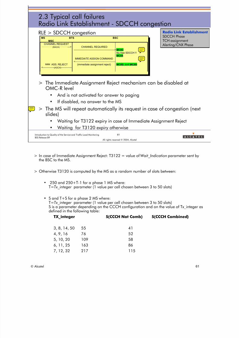
RLE > SDCCH congestion
> The Immediate Assignment Reject mechanism can be disabled atOMC-R level
• And is not activated for answer to paging• If disabled, no answer to the MS
> The MS will repeat automatically its request in case of congestion (nextslides)
• Waiting for T3122 expiry in case of Immediate Assignment Reject
• Waiting for T3120 expiry otherwise
MS BTS BSC
MSC
CHANNEL REQUEST-------------(RACH)--------- ---> CHANNEL REQUIRED
---------------------------------------------->MC8CNo free SDCCH !!
MC04IMMEDIATE ASSIGN COMMAND
<---------------------------------------------IMM. ASS. REJECT (immediate assignment reject) MC8D, and MC8B
<-------------(AGCH)-----------
Radio Link EstablishmentSDCCH PhaseTCH assignment Alerting/CNX Phase
> In case of Immediate Assignment Reject: T3122 = value of Wait_Indication parameter sent bythe BSC to the MS.
> Otherwise T3120 is computed by the MS as a random number of slots between:
• 250 and 250+T-1 for a phase 1 MS where: T=Tx_integer parameter (1 value per cell chosen between 3 to 50 slots)
• S and T+S for a phase 2 MS where:T=Tx_integer parameter (1 value per cell chosen between 3 to 50 slots)S is a parameter depending on the CCCH configuration and on the value of Tx_integer asdefined in the following table:
TX_integer S(CCCH Not Comb) S(CCCH Combined)
3, 8, 14, 50 55 41 4, 9, 16 76 52 5, 10, 20 109 58 6, 11, 25 163 86 7, 12, 32 217 115
© Alcatel 61
8/12/2019 QOS_B9 (Call Setup)
http://slidepdf.com/reader/full/qosb9-call-setup 62/388
62Introduction to Quality of the Service and Traffic Load MonitoringBSS Release B9
All rights reserved © 2004, Alcatel
2.3 Typical call failuresRadio Link Establishment - SDCCH congestion counter
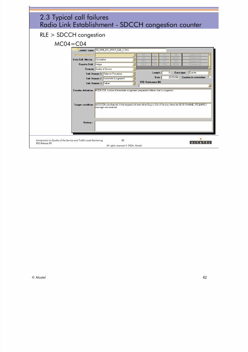
RLE > SDCCH congestion
MC04=C04
© Alcatel 62

8/12/2019 QOS_B9 (Call Setup)
http://slidepdf.com/reader/full/qosb9-call-setup 63/388
63Introduction to Quality of the Service and Traffic Load MonitoringBSS Release B9
All rights reserved © 2004, Alcatel
2.3 Typical call failuresRadio Link Establishment - SDCCH cong. consequences
RLE > SDCCH congestion
MAIN CONSEQUENCES
> The MS will try "max_retrans +1 " time before giving up
• Immediately for phase 1 MS
• After T3126 for phase 2 MS (still waiting for Immediate Assignmentduring this timer)
> In case of "max_retrans+1" failures, the MS will
• Either try an automatic cell reselection
• Or do nothing
> In case of LU, the MS will attempt a new LU request
> In case of Call establishment, the MS will not re-attempt automatically,it is up to the subscriber to try to set up the call again
Radio Link EstablishmentSDCCH PhaseTCH assignment Alerting/CNX Phase
© Alcatel 63

8/12/2019 QOS_B9 (Call Setup)
http://slidepdf.com/reader/full/qosb9-call-setup 64/388
64Introduction to Quality of the Service and Traffic Load MonitoringBSS Release B9
All rights reserved © 2004, Alcatel
2.3 Typical call failuresRadio Link Establishment - SDCCH cong. causes
RLE > SDCCH congestion
MAIN CAUSES
> Too much SDCCH "normal" traffic for cell SDCCH design
• Radio resource capacity not sufficient (too many calls)
• Inadequate LA design (too many LUs)
> "Common Transport Effect"
• Difficult to avoid for small cells
> Abnormal SDCCH traffic
• ”Phantom" channel requests (seen in SDCCH RF failure session)
• Neighboring cell barred
Radio Link EstablishmentSDCCH PhaseTCH assignment Alerting/CNX Phase
> SDCCH congestion can be too high because of the subscribers' traffic demand in terms of calls/ LU.
• Solution = add a TRX or site / redesign the LA plan
> High SDCCH congestion can be observed at peculiar period of the day due to a peak of LU
requests generated by a big group of subscribers entering a new LA at the same time (bus,train, plane).
• Solution = redesign the LA plan or play on radio parameters (CELL_RESELECT_HYSTERESIS, WI_OP)
> High SDCCH congestion can be abnormally observed without real MS traffic in case a highlevel of noise or the proximity of a non-GSM radio transmitter.
• Solution = change the BCCH frequency or put an RX filter
> High SDCCH congestion can also be abnormally observed in a cell in case one of its
neighboring cell is barred.• Solution = Remove the barring
© Alcatel 64

8/12/2019 QOS_B9 (Call Setup)
http://slidepdf.com/reader/full/qosb9-call-setup 65/388
65Introduction to Quality of the Service and Traffic Load MonitoringBSS Release B9
All rights reserved © 2004, Alcatel
2.3 Typical call failuresRadio Link Establishment - SDCCH cong. Resolution?
RLE > SDCCH congestion
DYNAMIC SDCCH ALLOCATION
> Too many SDCCHs will lead to a lack of TCH resources... and money.
> Too few SDCCH will result in SDCCH congestion. TCH channels cannotbe allocated and, once again, the operator 's revenue decreases.
> At OMC-R level, it is possible to configure:
• a set of static SDCCH/x timeslots to handle normal SDCCH traffic;
• a set of dynamic SDCCH/8 timeslots, which can be used for TCH traffic,or for SDCCH traffic depending on the need.
> "Dynamic SDCCH allocation" feature:• the BSS is automatically looking after varying SDCCH traffic
• adapted to the situations such as: change of LA, change of SMS traffic
> Useful in very dense (hierarchical) networks:
• optimize the SDCCH configuration becomes more important.
Radio Link EstablishmentSDCCH PhaseTCH assignment Alerting/CNX Phase
> This feature not only improves SDCCH congestion but also successful TCH assignment rates.> With the "Dynamic SDCCH allocation" feature, the BSS is automatically looking after varying SDCCH traffic and is particularly
adapted to the situations such as: change of LA, change of SMS traffic model, SDCCH traffic varying due to LCS.
> This feature is particularly useful in very dense (hierarchical) networks, where the effort to optimize the SDCCH configurationbecomes more important.
© Alcatel 65

8/12/2019 QOS_B9 (Call Setup)
http://slidepdf.com/reader/full/qosb9-call-setup 66/388
66Introduction to Quality of the Service and Traffic Load MonitoringBSS Release B9
All rights reserved © 2004, Alcatel
2.3 Typical call failuresRadio Link Establishment - SDCCH cong. Resolution?
RLE > SDCCH congestion
DYNAMIC SDCCH ALLOCATION
CHANNEL REQUESTCHANNEL REQUIRED
MS BTS BSC
(RACH)
If No free SDCCH, thenrun dynamic SDCCH/8timeslot allocation
algorithm. If allocation is successful, then
activate dynamic SDCCHsub-channeland serve request
If allocation was unsuccessful, then reject SDCCH request (possiblyusing the Immediate Assignment Reject procedure).
MC801a&b
MC802a&b
Radio Link EstablishmentSDCCH PhaseTCH assignment Alerting/CNX Phase
> SPECIFIC COUNTERS (Type 110 / Cell Level):• MC800 Average number of available dynamic SDCCH/8 timeslots.
• MC801a Average number of busy dynamic SDCCH/8 timeslots allocated as TCH (FR or HR).
• MC801b Maximum number of busy dynamic SDCCH/8 timeslots allocated as TCH (FR or HR).
• MC802a Average number of busy SDCCH sub-channels allocated on the dynamic SDCCH/8 timeslots.
• MC802b Maximum number of busy SDCCH sub-channels allocated on the dynamic SDCCH/8 timeslots.These four previous counters are”Inspection Counters” ; that means than the resource is checked regulary by the BSC and atthe end of the period, an average is done. Example: 3 physical chanels are defined as Dyn SDCCH and the counter give thefollowing indication:MC801a = 1.7 that means sometimes the 3 Dyn SD are allocated as TCH, sometimes only 2 of them, sometimes 1 or 0 andthe average is 1.7
> The FOLLOWING COUNTERS ARE IMPACTED BY the Dynamic SDCCH Allocation feature:• MC28, MC29 The Number of busy radio timeslots in TCH usage
takes into account the busy TCH timeslots and the dynamic SDCCH/8 timeslots allocated as TCH. • C30, MC31 The Number of busy SDCCH sub-channels
takes into account the SDCCH sub-channels allocated on the static and dynamic SDCCH/8 timeslots. • C370a, MC370a, C370b, MC370b The Number of times the radio timeslots are allocated for TCH usage (FR / HR)
takes into account the busy TCH timeslots and the dynamic SDCCH/8 timeslots allocated as TCH.
• C/MC380a/b C/MC381a/b The Cumulated time (in second) the radio timeslots are allocated for TCH usage (FR or HR)does not take care whether the TCHs are allocated on the TCH radio timeslot or on the dynamic SDCCH/8 timeslots.
• C39, MC390, C40, MC400 The Number of times or the Cumulated time (in second) the SDCCH sub-channels are busydoes not take care whether the SDCCH sub-channels are allocated on the static or dynamic SDCCH/x timeslot.
• C/MC34 C/MC380 The Cumulated time (in second) all TCHs / SDCCHs in the cell are busydoes not take care whether the TCHs / SDCCHs are allocated on the TCH radio timeslot /SDCCH/x timeslot or on the dynamic
SDCCH/8 timeslots.• C/MC320a/b/c/d/e Free TCH radio timeslots
count the free TCH timeslots and the free dynamic SDCCH/8 timeslots.
© Alcatel 66

8/12/2019 QOS_B9 (Call Setup)
http://slidepdf.com/reader/full/qosb9-call-setup 67/388
SDCCHCongestion
SDCCHRadio Failure
SDCCH
BSS Problem
67Introduction to Quality of the Service and Traffic Load MonitoringBSS Release B9
All rights reserved © 2004, Alcatel
2.3 Typical call failuresRadio Link Establishment - SDCCH radio failure
> Main failure cases for Radio Link Establishment
SDCCH Access Failure
SDCCHCongestion
SDCCHRadio Failure
SDCCHBSS Problem
Radio Link EstablishmentSDCCH PhaseTCH assignment Alerting/CNX Phase
© Alcatel 67

8/12/2019 QOS_B9 (Call Setup)
http://slidepdf.com/reader/full/qosb9-call-setup 68/388
68Introduction to Quality of the Service and Traffic Load MonitoringBSS Release B9
All rights reserved © 2004, Alcatel
2.3 Typical call failuresRadio Link Establishment - SDCCH radio access failure
RLE > SDCCH RF Failure
MS BTS BSC MSC
CHANNEL REQUEST-------------(RACH)------------> CHANNEL REQUIRED
----------------------------------------------> MC8CCHANNEL ACTIVATION (SDCCH)
<--------------------------------------------- MC148CHANNEL ACTIVATION ACK
---------------------------------------------->IMMEDIATE ASSIGN COMMAND
IMMEDIATE ASSIGN <--------------------------------------------- start T3101
<------------(AGCH)------------ MC8BIMMEDIATE ASSIGN
-------(SDCCH)-----XT3101expiry->“radio failure”MC149
Radio Link EstablishmentSDCCH PhaseTCH assignment Alerting/CNX Phase
> MC149 counts the number of SDCCH access failures due to radio problems.
© Alcatel 68

8/12/2019 QOS_B9 (Call Setup)
http://slidepdf.com/reader/full/qosb9-call-setup 69/388
69Introduction to Quality of the Service and Traffic Load MonitoringBSS Release B9
All rights reserved © 2004, Alcatel
2.3 Typical call failuresRadio Link Establishment - real radio problems
RLE > SDCCH RF Failure
Main causes > real radio problems
> Unbalanced cell power budget
> Bad coverage (for example a moving car)
> Interference (for example downlink)
In case of radio failure, the MS will retry as for SDCCH congestion
Radio Link EstablishmentSDCCH PhaseTCH assignment Alerting/CNX Phase
> Unbalanced Power Budget:
AGCH
RACH
Max Path Loss DL
Max Path Loss UL
> Bad coverage: building
BTS
Channel Request
Access Grant
> Interference:
DL interference area
AGCH lost
RACH
© Alcatel 69

8/12/2019 QOS_B9 (Call Setup)
http://slidepdf.com/reader/full/qosb9-call-setup 70/388
70Introduction to Quality of the Service and Traffic Load MonitoringBSS Release B9
All rights reserved © 2004, Alcatel
2.3 Typical call failuresRadio Link Establishment - Ghost RACH (1/7)
RLE > SDCCH RF Failure
Main causes > "Phantom/Ghost/Spurious/Dummy ... RACH"
> Channel request received but not sent: 3 causes
• Noise decoding
• Reception of channel request sent to a neighboring cell
• Reception of HO_ACCESS sent to a neighboring cell
© Alcatel 70

8/12/2019 QOS_B9 (Call Setup)
http://slidepdf.com/reader/full/qosb9-call-setup 71/388
71Introduction to Quality of the Service and Traffic Load MonitoringBSS Release B9
All rights reserved © 2004, Alcatel
2.3 Typical call failuresRadio Link Establishment - Ghost RACH (2/7)
RLE > SDCCH RF Failure
Main causes > "Phantom/Ghost/Spurious/Dummy ... RACH"
> Example of a channel required message
> For this Channel Required, the establishment cause is valid (Call re-establishment) but the Access Delay (corresponding to the distance between the MS and the BTS) is high.
> Indeed the Access Delay being equal to the Timing Advance is coded in slot unit representing adistance of 550m. It can take values from 0 (0m) to 63 (35km).
> Thus the Channel Required above is received from an MS located at 19km from the site. It maytherefore be rather a ghost RACH than a real MS which wants re-establish a call.
> In Alcatel BSS, there is possibility to filter the Channel Required received from a distance greaterthan a distance defined as a parameter value: RACH_TA_FILTER tunable on a per cell basis.Caution should be taken since a too low value may reduce the network coverage.
© Alcatel 71

8/12/2019 QOS_B9 (Call Setup)
http://slidepdf.com/reader/full/qosb9-call-setup 72/388
72Introduction to Quality of the Service and Traffic Load MonitoringBSS Release B9
All rights reserved © 2004, Alcatel
2.3 Typical call failuresRadio Link Establishment - Ghost RACH causes (3/7)
RLE > SDCCH RF Failure
Main causes > "Phantom RACH" >noise decoding
> GSM 05.05: " 0.02 % of Rach Frame can be decoded without errorwithout real input signal" (No impact for the system)
• BCCH not combined: 51 Rach/Multi Frame > (3600 * 1000) ms / 4.615ms at 0.02 %: 156 dummy RACH/hour
• BCCH combined: 27/51 RACH/Multi-Frame > 83 dummy RACH/hour
• 3/8 of causes (field of channel request, 5 valid causes over 8) will beunvalid
• Example of induced SDCCH traffic:(5/8*156*T3101 (3 sec))/3600 = 0.08 Erlang SDCCH
> Some tips:
• Dummy Rach load depends on minimum level for decoding configured inEvolium BTS
• During period with low real traffic (night), high rate of dummy RACH
• For dummy RACH, the channel required has a random value of TA
STRUCTURE of the MULTIFRAME in TIME SLOT 0
(Non-combined BCCH)
-
UPLINK
R R R RR R R R R R R RR R R R R R R RR R R R R R R RR R R R R R R RR R R RR R R RR R R R R R
(Multiframes of 51 frames)
OWNLINK
f s b b b b C C C C31 51 1211 2 3 4 5 6 7 8 9 10 20 41
f s f s f s f sC C C C C C C C C C C C C C C C C C C C C C C C C C C C C C C C -f s
f = FCCH s = SCH b = BCCH C C C C = CCCH (PCH or AGCH) R = RACH
(Combined BCCH)
OWNLINK
UPLINK
F S B C FS F S F S -F S C D0 D1 D2 D3 A0 A1
F S B C FS F S F S -F S C D0 D1 D2 D3 A2 A3
R R R RR R R R R R RR R R R R RR R R R R R3 A2 A3 D0 D1 D2
R R R R R R R R R R RR R R R R R R R R R RR3 A0 A1 D0 D1 D2
F = FCCH S = SCH B = BCCH C = CCCH (PCH or AGCH) R = RACH Dn/An = SDCCH/SACCH/4
51 multiframe duration = 51 x 8 x 0,577 = 235ms
© Alcatel 72

8/12/2019 QOS_B9 (Call Setup)
http://slidepdf.com/reader/full/qosb9-call-setup 73/388
73Introduction to Quality of the Service and Traffic Load MonitoringBSS Release B9
All rights reserved © 2004, Alcatel
2.3 Typical call failuresRadio Link Establishment - Ghost RACH causes (4/7)
RLE > SDCCH RF Failure
Main causes > "Phantom RACH" >noise decoding
> No subscriber -> no impact for subscriber
> But MC149 incremented -> SDCCH RF access failure is impacted
MS BTS BSC MSC
CHANNEL REQUIRED
----------------------------------------------> MC8C
CHANNEL ACTIVATION (SDCCH)
<--------------------------------------------- MC148
CHANNEL ACTIVATION ACK
---------------------------------------------->
IMMEDIATE ASSIGN COMMAND
IMMEDIATE ASSIGN <--------------------------------------------- start T3101
<------------ (AGCH) ------------ MC8B
T3101expiry
->“radio failure
MC149
© Alcatel 73
8/12/2019 QOS_B9 (Call Setup)
http://slidepdf.com/reader/full/qosb9-call-setup 74/388
74Introduction to Quality of the Service and Traffic Load MonitoringBSS Release B9
All rights reserved © 2004, Alcatel
2.3 Typical call failuresRadio Link Establishment - Ghost RACH causes (5/7)
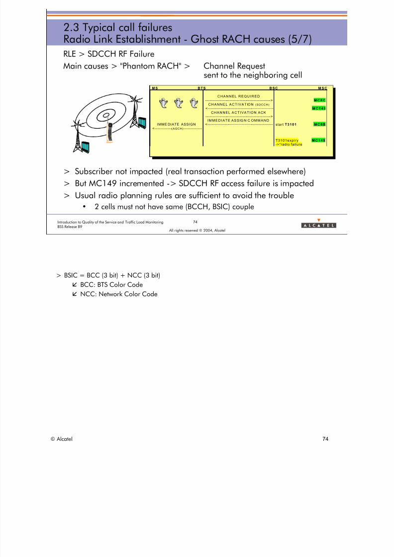
RLE > SDCCH RF Failure
Main causes > "Phantom RACH" > Channel Requestsent to the neighboring cell
> Subscriber not impacted (real transaction performed elsewhere)
> But MC149 incremented -> SDCCH RF access failure is impacted
> Usual radio planning rules are sufficient to avoid the trouble
• 2 cells must not have same (BCCH, BSIC) couple
M S BTS BSC M S C
CHANNEL REQUIRED----------------------------------------------> M C8C
CHANNEL ACTIVATION (SDCCH)
<--------------------------------------------- M C148
CHANNEL ACTIVATION ACK---------------------------------------------->IMMEDIATE ASSIG N C OMMAND
IMME DIATE ASSIGN <--------------------------------------------- start T3101 MC8B<------------(AGCH)------------
T3101expiry M C149->“radio fai lure
> BSIC = BCC (3 bit) + NCC (3 bit)
� BCC: BTS Color Code
� NCC: Network Color Code
© Alcatel 74

8/12/2019 QOS_B9 (Call Setup)
http://slidepdf.com/reader/full/qosb9-call-setup 75/388
75Introduction to Quality of the Service and Traffic Load MonitoringBSS Release B9
All rights reserved © 2004, Alcatel
2.3 Typical call failuresRadio Link Establishment - Ghost RACH causes (6/7)
RLE > SDCCH RF Failure
Main causes > "Phantom RACH" > Channel Request
due to handover
> During HO, the first message sent to the target cell is HO Access
> This message is an Access Burst like Channel Request
> If received on BCCH, can be understood as a Channel Request(RACH)
> A new case of "Phantom RACH"
© Alcatel 75

8/12/2019 QOS_B9 (Call Setup)
http://slidepdf.com/reader/full/qosb9-call-setup 76/388
76Introduction to Quality of the Service and Traffic Load MonitoringBSS Release B9
All rights reserved © 2004, Alcatel
2.3 Typical call failuresRadio Link Establishment - Ghost RACH causes (7/7)
RLE > SDCCH RF Failure
Main causes > "Phantom RACH" > Channel Request
due to handoverThis case is the most dangerous
> The MS sends usually a sequence of HO Access message, everyframe
> In some cases, this can create a phantom RACH if
• The frequency of the TCH is identical or adjacent to the one ofinterfered BCCH
> Characteristics of such phantom RACH (Channel Required)• Subsequent frame number
• Random, but stable timing advance
> Can block very easily SDCCH
© Alcatel 76

8/12/2019 QOS_B9 (Call Setup)
http://slidepdf.com/reader/full/qosb9-call-setup 77/388
SDCCHCongestion
SDCCHRadio Failure
SDCCH
BSS Problem
77Introduction to Quality of the Service and Traffic Load MonitoringBSS Release B9
All rights reserved © 2004, Alcatel
2.3 Typical call failuresRadio Link Establishment - BSS failure
> Main failure cases for Radio Link Establishment
Radio Link EstablishmentSDCCH PhaseTCH assignment Alerting/CNX Phase
SDCCH Access Failure
SDCCHCongestion
SDCCHRadio Failure
SDCCHBSS Problem
© Alcatel 77

8/12/2019 QOS_B9 (Call Setup)
http://slidepdf.com/reader/full/qosb9-call-setup 78/388
78Introduction to Quality of the Service and Traffic Load MonitoringBSS Release B9
All rights reserved © 2004, Alcatel
2.3 Typical call failuresRadio Link Establishment - BSS problem
RLE > BSS problem
> No specific counter
MS BTS BSC MSC
CHANNEL REQUEST-------------(RACH)------------> CHANNEL REQUIRED
----------------------------------------------> MC8CCHANNEL ACTIVATION (SDCCH)
<--------------------------------------------- MC148CHANNEL ACTIVATION ACK
---------------------------------------------->IMMEDIATE ASSIGN COMMAND
IMMEDIATE ASSIGN <--------------------------------------------- start T3101<------------(AGCH)------------ MC8B
SABM (L3 info)------------(SDCCH)------------>
Radio Link EstablishmentSDCCH PhaseTCH assignment Alerting/CNX Phase
> BSS Problems are difficult to specify a priori. It is better to deduce them from other counterswhich are easier to implement thus more reliable.
© Alcatel 78

8/12/2019 QOS_B9 (Call Setup)
http://slidepdf.com/reader/full/qosb9-call-setup 79/388
79Introduction to Quality of the Service and Traffic Load MonitoringBSS Release B9
All rights reserved © 2004, Alcatel
2.3 Typical call failuresRadio Link Establishment - counters
RLE counters
Request MC8C
GPRS causes P62C
GSM invalid causes unknown
Preparation GSM valid causes unknown
Congestion MC04
BSS Pb unknown
Execution Attempt MC148
Radio Access Failure MC149
BSS Pb MC148 - (MC01+MC02) - MC149
Success MC01+MC02
Radio Link Establishment
REQUEST
Congestion
Radio access failure
BSS problem
Preparation Failure
Execution Failure
ATTEMPT
SUCCESS
GPRS causes GSM/GPRS invalid causes GSM valid causes
BSS problem
Radio Link EstablishmentSDCCH PhaseTCH assignment Alerting/CNX Phase
> Statistically a ghost RACH can correspond to any kind of establishment cause: valid andinvalid.
> As ghost RACH which corresponds to a GSM valid cause will lead to an SDCCH allocationwhich will not be seized by an MS, it will lead to the incrementation of MC149 counter andtherefore counted as an SDCCH access failure due to radio.
© Alcatel 79

8/12/2019 QOS_B9 (Call Setup)
http://slidepdf.com/reader/full/qosb9-call-setup 80/388
2.3 Typical call failuresRadio Link Establishment - indicators
TYPICAL CALL FAILURES: RLE indicators
SDNAFLBNSDNAFLRNSDNACGNSDNAFSUNSDNAFLR
Radio Link EstablishmentSDCCH PhaseTCH assignment Alerting/CNX Phase
80Introduction to Quality of the Service and Traffic Load MonitoringBSS Release B9
All rights reserved © 2004, Alcatel
> Refer to BSS - DEFINITION OF QUALITY OF SERVICE INDICATORS:
> GLOBAL Quality of service INDICATORS > SDCCH > Assignment Phase
• SDNAUR: SDCCH assignment unsuccess rate
• SDNACGR: SDCCH assignment failure rate due to congestion (Global)
• SDNAFLRR: SDCCH assignment failure rate due to radio
• SDNAFLBR: SDCCH assignment failure rate due to BSS problem
> A SDCCH radio access failure due to ghost RACH occurrence is easily observed during lowtraffic hour (night time) since ghost RACHs are almost the only cause of failure.
© Alcatel 80

8/12/2019 QOS_B9 (Call Setup)
http://slidepdf.com/reader/full/qosb9-call-setup 81/388
81Introduction to Quality of the Service and Traffic Load MonitoringBSS Release B9
All rights reserved © 2004, Alcatel
2.3 Typical call failuresSDCCH phase - OC success
Successful SDCCH phase: OC call
> transparent message: no dedicated counters
MS BTS BSC MSC
SDCCH Phase : Originating Call case
< ------------------------------------------------------------------------------------------------------------------------AUTHENTICATION REQUEST
------------------------------------------------------------------------------------------------------------------------- >AUTHENTICATION RESPONSE
< ------------------------------------------------------------------------------------------------------------------------CIPHERING MODE COMMAND
------------------------------------------------------------------------------------------------------------------------- >CIPHERING MODE COMPLETE
------------------------------------------------------------------------------------------------------------------------- >SETUP
< ------------------------------------------------------------------------------------------------------------------------CALL PROCEEDING
Radio Link EstablishmentSDCCH PhaseTCH assignment Alerting/CNX Phase
> Transparent messages (DTAP) are used in order the NSS performs control procedures to enablethe MS to set up a speech call.
> Authentication: Checks that the Mobile Station is the required station and not an intruder.
> Ciphering: All Information (signaling, Speech and Data) is sent in cipher mode, to avoidmonitoring and intruders (who could analyze signaling data).
> Setup/Call Processing: call is being processed between the calling Party and the Called Party.
© Alcatel 81

8/12/2019 QOS_B9 (Call Setup)
http://slidepdf.com/reader/full/qosb9-call-setup 82/388
82Introduction to Quality of the Service and Traffic Load MonitoringBSS Release B9
All rights reserved © 2004, Alcatel
2.3 Typical call failuresSDCCH phase - TC success
Successful SDCCH phase: TC call
> transparent message: no dedicated counters
MS BTS BSC MSC
SDCCH Phase : Terminating Call case
< ------------------------------------------------------------------------------------------------------------------------AUTHENTICATION REQUEST
------------------------------------------------------------------------------------------------------------------------- >AUTHENTICATION RESPONSE
< ------------------------------------------------------------------------------------------------------------------------CIPHERING MODE COMMAND
------------------------------------------------------------------------------------------------------------------------- >CIPHERING MODE COMPLETE
< ------------------------------------------------------------------------------------------------------------------------SETUP
------------------------------------------------------------------------------------------------------------------------- >CALL CONFIRM
Radio Link EstablishmentSDCCH PhaseTCH assignment Alerting/CNX Phase
> Setup/Call Confirm: the call is being processed between the Calling Party and the Called Party.
© Alcatel 82
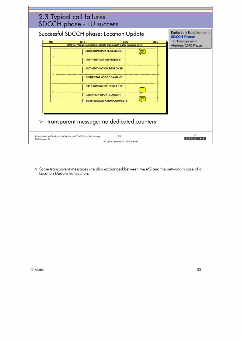
8/12/2019 QOS_B9 (Call Setup)
http://slidepdf.com/reader/full/qosb9-call-setup 83/388
83Introduction to Quality of the Service and Traffic Load MonitoringBSS Release B9
All rights reserved © 2004, Alcatel
2.3 Typical call failuresSDCCH phase - LU success
Successful SDCCH phase: Location Update
> transparent message: no dedicated counters
MS BTS BSC MSC
SDCCH Phase : Location Update Case (with TMSI reallocation)
------------------------------------------------------------------------------------------------------------------------- >LOCATION UPDATE REQUEST
< ------------------------------------------------------------------------------------------------------------------------AUTHENTICATION REQUEST
------------------------------------------------------------------------------------------------------------------------- >AUTHENTICATION RESPONSE
< ------------------------------------------------------------------------------------------------------------------------CIPHERING MODE COMMAND
------------------------------------------------------------------------------------------------------------------------- >CIPHERING MODE COMPLETE
< ------------------------------------------------------------------------------------------------------------------------LOCATION UPDATE ACCEPT
------------------------------------------------------------------------------------------------------------------------- >TMSI REALLOCATION COMPLETE
Radio Link EstablishmentSDCCH PhaseTCH assignment Alerting/CNX Phase
> Some transparent messages are also exchanged between the MS and the network in case of aLocation Update transaction.
© Alcatel 83
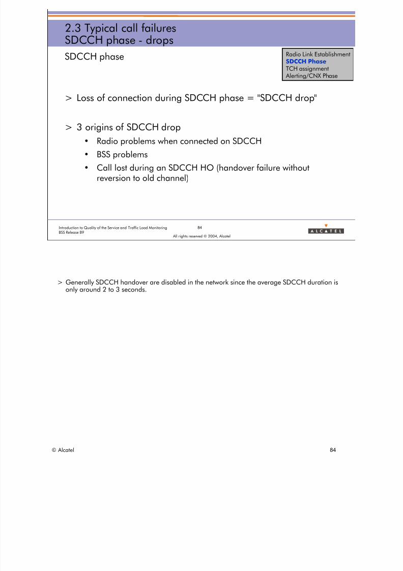
8/12/2019 QOS_B9 (Call Setup)
http://slidepdf.com/reader/full/qosb9-call-setup 84/388
84Introduction to Quality of the Service and Traffic Load MonitoringBSS Release B9
All rights reserved © 2004, Alcatel
2.3 Typical call failuresSDCCH phase - drops
SDCCH phase
> Loss of connection during SDCCH phase = "SDCCH drop"
> 3 origins of SDCCH drop
• Radio problems when connected on SDCCH
• BSS problems
• Call lost during an SDCCH HO (handover failure withoutreversion to old channel)
Radio Link EstablishmentSDCCH PhaseTCH assignment Alerting/CNX Phase
> Generally SDCCH handover are disabled in the network since the average SDCCH duration isonly around 2 to 3 seconds.
© Alcatel 84
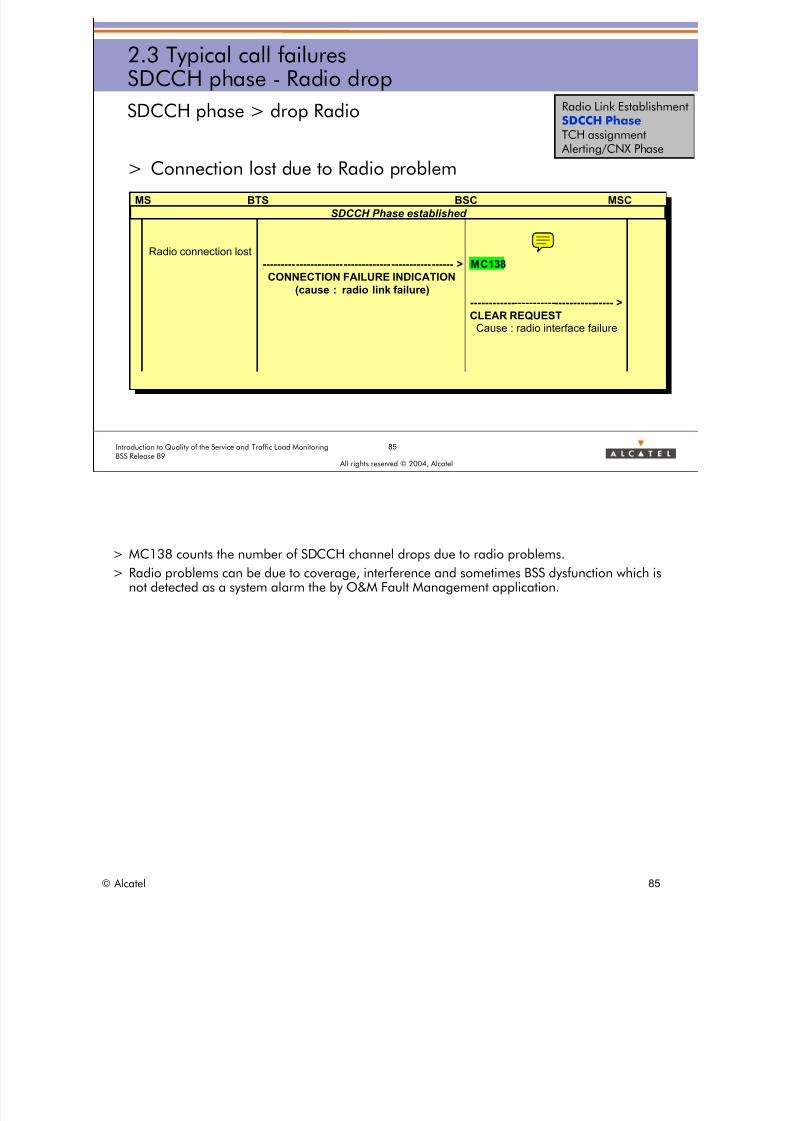
8/12/2019 QOS_B9 (Call Setup)
http://slidepdf.com/reader/full/qosb9-call-setup 85/388
85Introduction to Quality of the Service and Traffic Load MonitoringBSS Release B9
All rights reserved © 2004, Alcatel
2.3 Typical call failuresSDCCH phase - Radio drop
SDCCH phase > drop Radio
> Connection lost due to Radio problem
MS BTS BSC MSC
SDCCH Phase established
Radio connection lost---------------------------------------------------- > MC138
CONNECTION FAILURE INDICATION
(cause : radio link failure)
--------------------------------------- >
CLEAR REQUESTCause : radio interface failure
Radio Link EstablishmentSDCCH PhaseTCH assignment Alerting/CNX Phase
> MC138 counts the number of SDCCH channel drops due to radio problems.
> Radio problems can be due to coverage, interference and sometimes BSS dysfunction which isnot detected as a system alarm the by O&M Fault Management application.
© Alcatel 85

8/12/2019 QOS_B9 (Call Setup)
http://slidepdf.com/reader/full/qosb9-call-setup 86/388
86Introduction to Quality of the Service and Traffic Load MonitoringBSS Release B9
All rights reserved © 2004, Alcatel
2.3 Typical call failuresSDCCH phase - BSS drop
SDCCH phase > drop BSS
> Connection lost due BSS problem
MS BTS BSC MSC
SDCCH Phase established
MC137
--------------------------------------- >
CLEAR REQUEST
Cause : O&M interventionCause : radio interface failure
Radio Link EstablishmentSDCCH PhaseTCH assignment Alerting/CNX Phase
> MC137 counts the number of SDCCH channel drops due to BSS problems.
> A BSS problem can be a BTS/BSC hardware or software failure. It can also be due to a problemon the Abis interface (due to Micro Wave transmission for instance).
© Alcatel 86

8/12/2019 QOS_B9 (Call Setup)
http://slidepdf.com/reader/full/qosb9-call-setup 87/388
87Introduction to Quality of the Service and Traffic Load MonitoringBSS Release B9
All rights reserved © 2004, Alcatel
2.3 Typical call failuresSDCCH phase - HO drop
SDCCH phase > drop HO
> Connection lost during Handover
MS BTS BSC MSC
SDCCH Phase established
HO FAILURE WITHOUT REVERSION MC07
--------------------------------------- >CLEAR REQUEST
Radio Interface Message Failure (Alcatel)
Radio Link EstablishmentSDCCH PhaseTCH assignment Alerting/CNX Phase
> MC07 counts the number of SDCCH channel drops due to handover failure.
© Alcatel 87

8/12/2019 QOS_B9 (Call Setup)
http://slidepdf.com/reader/full/qosb9-call-setup 88/388
88Introduction to Quality of the Service and Traffic Load MonitoringBSS Release B9
All rights reserved © 2004, Alcatel
2.3 Typical call failuresSDCCH phase - counters
SDCCH phase counters
SDCCH connection MC01+MC02+MC10
SDCCH Drop Drop radio MC138
Drop BSS MC137
Drop HO MC07
SDCCH Phase
TCH assignment phase SDCCH drop
SDCCH connection
Normal release
Drop radio
Drop BSS
Drop HO
Radio Link EstablishmentSDCCH PhaseTCH assignment Alerting/CNX Phase
© Alcatel 88
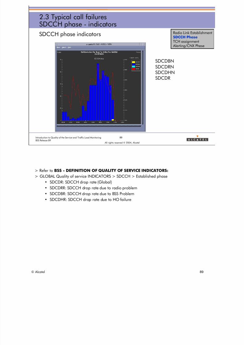
8/12/2019 QOS_B9 (Call Setup)
http://slidepdf.com/reader/full/qosb9-call-setup 89/388
2.3 Typical call failuresSDCCH phase - indicators
SDCCH phase indicators
SDCDBN
SDCDRNSDCDHNSDCDR
Radio Link EstablishmentSDCCH PhaseTCH assignment Alerting/CNX Phase
89Introduction to Quality of the Service and Traffic Load MonitoringBSS Release B9
All rights reserved © 2004, Alcatel
> Refer to BSS - DEFINITION OF QUALITY OF SERVICE INDICATORS:
> GLOBAL Quality of service INDICATORS > SDCCH > Established phase
• SDCDR: SDCCH drop rate (Global)
• SDCDRR: SDCCH drop rate due to radio problem
• SDCDBR: SDCCH drop rate due to BSS Problem
• SDCDHR: SDCCH drop rate due to HO failure
© Alcatel 89
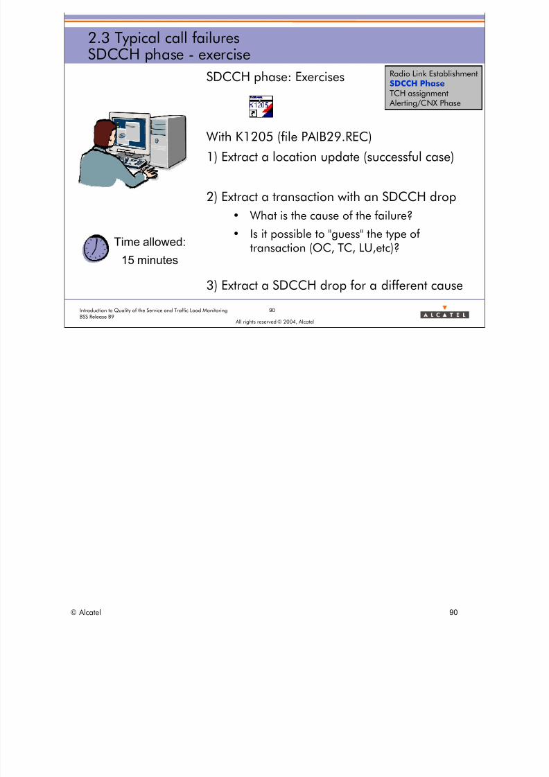
8/12/2019 QOS_B9 (Call Setup)
http://slidepdf.com/reader/full/qosb9-call-setup 90/388
90Introduction to Quality of the Service and Traffic Load MonitoringBSS Release B9
All rights reserved © 2004, Alcatel
2.3 Typical call failuresSDCCH phase - exercise
SDCCH phase: Exercises
With K1205 (file PAIB29.REC)
1) Extract a location update (successful case)
2) Extract a transaction with an SDCCH drop
• What is the cause of the failure?
• Is it possible to "guess" the type oftransaction (OC, TC, LU,etc)?
3) Extract a SDCCH drop for a different cause
Time allowed:
15 minutes
Radio Link EstablishmentSDCCH PhaseTCH assignment Alerting/CNX Phase
© Alcatel 90

8/12/2019 QOS_B9 (Call Setup)
http://slidepdf.com/reader/full/qosb9-call-setup 91/388
91Introduction to Quality of the Service and Traffic Load MonitoringBSS Release B9
All rights reserved © 2004, Alcatel
2.3 Typical call failuresTCH assignment - success
TCH assignment success case
> T3107: guard timer for TCH assignment
MS BTS BSC MSC
TCH ASSIGNMENT PHASE (OC or TC)
< -----------------------------------
ASSIGNMENT REQUEST< --------------------------------------------------------
PHYSICAL CONTEXT REQUEST
-------------------------------------------------------- >
PHYSICAL CONTEXT CONFIRM
< -------------------------------------------------------- MC703
CHANNEL ACTIVATION (TCH)
-------------------------------------------------------- >
CHANNEL ACTIVATION ACKNOWLEDGE
< ----------------------------------------------------------------------------------- Start T3107
(SDCCH) ASSIGNMENT COMMAND
---------------------- >
TCH SABM ----------------------- ------------------------ --------- >
< -- --- --- -- --- -- --- ---- ESTABLISH INDICATION
UA
-------------------------- --------------------- ----------------------- ------------- > Stop T3107ASSIGNMENT COMPLETE MC718
----------------------------------- >
ASSIGNMENT COMPLETE
MC140a
MC140b
MC460a
Radio Link EstablishmentSDCCH PhaseTCH assignment Alerting/CNX Phase
> MC703 counts the number of TCH channels activated (therefore allocated) in a cell.
> MC718 counts the number of MSs which have successfully accessed a TCH in a cell as part of acall establishment (Normal Assignment).
> Both counters are implemented at TRX level.
> MC140a counts the number of normal assignment requests for TCH establishment.
> MC140b counts the number of normal assignment commands for TCH establishment.
> Both counters in order to discriminate BSS problems in Preparation and Execution phases.
> MC460a is a counter for type 110: NB_TCH_EMERGENCY_HO_PRESERVATION:Definition: Number of high priority TCH requests served when:
• the number of free TCH timeslots is less than or equal to NUM_TCH_EGNCY_HO.
• the queue for this cell is not empty.
> MC140a, MC140b and MC460 are given at Cell level
© Alcatel 91

8/12/2019 QOS_B9 (Call Setup)
http://slidepdf.com/reader/full/qosb9-call-setup 92/388
92Introduction to Quality of the Service and Traffic Load MonitoringBSS Release B9
All rights reserved © 2004, Alcatel
2.3 Typical call failuresTCH assignment - TCH congestion
TCH assignment > congestion
> 5 causes of congestion ⇒5 counters: C612A, B, C, D, Ewhenever
– Queuing is not allowed
– Queue is Full– T11 expires
– RTCH request is removed from the queue due to a higher priorityrequest to be queued
– No Abis-TCH resource is available
MS BTS BSC MSC
TCH ASSIGNMENT PHASE (OC or TC)
< -----------------------------------------------
ASSIGNMENT REQUEST
No RTCH available on requested cell MC812
------------------------------------------------ >
ASSIGNMENT FAILURE
Cause No Radio Resource Available
Radio Link EstablishmentSDCCH PhaseTCH assignment Alerting/CNX Phase
> C612E: Number of 08.08 ASSIGNMENT REQUEST for TCH normal assignment rejected due tocongestion on the Abis interface. (from B8)
> Therefore B6 counter MC612 is replaced by MC812 from B7.MC812 = C612A+C612B+C612C+C612D+C612E of PM Type 1.
> But as C612E was in restriction in B8 (always = 0) then MC812(B7) = MC612(B6)
> MC612A, MC612B, MC612C, MC612D also exist in PM Type 110.> A TCH request is attached a Priority Level from 1 (highest priority) to 14 (lowest priority).
© Alcatel 92

8/12/2019 QOS_B9 (Call Setup)
http://slidepdf.com/reader/full/qosb9-call-setup 93/388
93Introduction to Quality of the Service and Traffic Load MonitoringBSS Release B9
All rights reserved © 2004, Alcatel
2.3 Typical call failuresTCH assignment - radio failure
TCH assignment > radio failure
> Radio problemMS BTS BSC MSC
TCH ASSIGNMENT PHASE (OC or TC)
< -----------------------------------
ASSIGNMENT REQUEST
< --------------------------------------------------------
PHYSICAL CONTEXT REQUEST
-------------------------------------------------------- >
PHYSICAL CONTEXT CONFIRM
< -------------------------------------------------------- MC703
CHANNEL ACTIVATION (TCH)
-------------------------------------------------------- >
CHANNEL ACTIVATION ACKNOWLEDGE
< ----------------------------------------------------------------------------------- Start T3107
(SDCCH) ASSIGNMENT COMMAND
SABM
----(TCH)------X
T3107 Expiry
MC746B
----------------------------------- >
ASSIGNMENT FAILURE
Radio interface failure
MC140a
MC140b
Radio Link EstablishmentSDCCH PhaseTCH assignment Alerting/CNX Phase
> MC746B counts the number of TCH access failures due to radio problems.
> MC746B counter is implemented at TRX level from B7.
> In case of TCH access failure, the MS will try to revert back to the SDCCH channel. Whether itsucceeds in reverting to the SDCCH or not the call establishment fails. On the other hand someMSCs may resend the ASSIGNMENT REQUEST again.
© Alcatel 93

8/12/2019 QOS_B9 (Call Setup)
http://slidepdf.com/reader/full/qosb9-call-setup 94/388
94Introduction to Quality of the Service and Traffic Load MonitoringBSS Release B9
All rights reserved © 2004, Alcatel
2.3 Typical call failuresTCH assignment - BSS problem
TCH assignment > BSS problem
> BSS problem (Abis, BTS/BSC HW or SW)MS BTS BSC MSC
TCH ASSIGNMENT PHASE (OC or TC)
< -----------------------------------
ASSIGNMENT REQUEST
< --------------------------------------------------------
PHYSICAL CONTEXT REQUEST
-------------------------------------------------------- >
PHYSICAL CONTEXT CONFIRM
< -------------------------------------------------------- MC703
CHANNEL ACTIVATION (TCH)
-------------------------------------------------------- >
CHANNEL ACTIVATION ACKNOWLEDGE
< ----------------------------------------------------------------------------------- Start T3107
(SDCCH) ASSIGNMENT COMMAND
SABM
----(TCH)---- >
MC1 B
MC140a
MC140b
No specific counter
Radio Link EstablishmentSDCCH PhaseTCH assignment Alerting/CNX Phase
> The number of TCH Assignment failures due to BSS Pb can be correctly deduced anddistinguished for preparation and execution phases from B8 with the 2 counters MC140a andMC140b.(see the next slide)
> B7 counters MC14b has been removed.
© Alcatel 94

8/12/2019 QOS_B9 (Call Setup)
http://slidepdf.com/reader/full/qosb9-call-setup 95/388
95Introduction to Quality of the Service and Traffic Load MonitoringBSS Release B9
All rights reserved © 2004, Alcatel
2.3 Typical call failuresTCH assignment - counters
TCH assignment counters
Congestion
ATTEMPT
Radio accessfailure
SUCCESS
BSS problem
Preparation Failure
Execution Failure
REQUEST
BSS problemTCH Assignment
Preparation Request MC140a
Congestion MC812
BSS Pb MC140a-MC140b-MC812
Execution Attempt MC140b
Radio Access Failure MC746b
BSS Pb MC140b-MC718-MC746b
Success MC718
Radio Link EstablishmentSDCCH PhaseTCH assignment Alerting/CNX Phase
© Alcatel 95

8/12/2019 QOS_B9 (Call Setup)
http://slidepdf.com/reader/full/qosb9-call-setup 96/388
2.3 Typical call failuresTCH assignment - indicators
TCH Assignment indicators
TCNAFLBN
TCNAFLRNTCNACGNTCAHCANTCNAUR
Radio Link EstablishmentSDCCH PhaseTCH assignment Alerting/CNX Phase
96Introduction to Quality of the Service and Traffic Load MonitoringBSS Release B9
All rights reserved © 2004, Alcatel
> Refer to BSS - DEFINITION OF QUALITY OF SERVICE INDICATORS
> GLOBAL Quality of service INDICATORS > RTCH > Assignment Phase
• TCNAUR: TCH assignment unsuccess rate (Global)
• TCNACGR: TCH assignment failure rate due to congestion
• TCNAFLRR: TCH assignment failure rate due to radio problems
• TCNAFLBR: TCH assignment failure rate due to BSS Problems.
> From B7.2 some indicators can be provided on a per TRX basis due to the availability of
counters provided per TRX in Type 110:• TCNAEFR = RTCH_assign_efficiency_rate (RNO name) = MC718 / MC703
– Rate of successful RTCH seizures in relation to all RTCHs allocated, during the TCHassignment procedure.
• TCNAAFLRR = RTCH_assign_allocated_fail_radio_rate (RNO name) = MC746B /MC703
– Rate of RTCH seizures failed during the normal assignment procedure because ofradio problems in relation to all RTCHs allocated for TCH assignment procedure.
> This will help a lot to detect bad QOS due to TRX hardware related problem.
© Alcatel 96

8/12/2019 QOS_B9 (Call Setup)
http://slidepdf.com/reader/full/qosb9-call-setup 97/388
97Introduction to Quality of the Service and Traffic Load MonitoringBSS Release B9
All rights reserved © 2004, Alcatel
2.3 Typical call failuresTCH assignment - exercise
TCH assignment failure
With K1205 (file PAIB29.REC)
1) Find and extract a case of TCH congestion(if any)
2) Find and extract a case of Assignment
Failure due to Radio Problem (if any)Time allowed:
15 minutes
Radio Link EstablishmentSDCCH PhaseTCH assignment Alerting/CNX Phase
© Alcatel 97

8/12/2019 QOS_B9 (Call Setup)
http://slidepdf.com/reader/full/qosb9-call-setup 98/388
2.3 Typical call failuresTCH phase - success
98Introduction to Quality of the Service and Traffic Load MonitoringBSS Release B9
All rights reserved © 2004, Alcatel
TCH phase:
> OC
> TC
• Transparent messages for BSS, no specific counters
• TCH DROP: any problems occurring after TCH assignment(during or after connection) cannot be discriminated
MS BTS BSC MSC
Alerting Connection Phase (OC case) : ringing phase
< ---------------------------------------------------------------------------------------------------------------------------
ALERTING
< ---------------------------------------------------------------------------------------------------------------------------
CONNECT
--------------------------------------------------------------------------------------------------------------------------- >
CONNECT ACK
MS BTS BSC MSC
Alerting Connection Phase : TC case
--------------------------------------------------------------------------------------------------------------------------- >
ALERTING
--------------------------------------------------------------------------------------------------------------------------- >
CONNECT
< ---------------------------------------------------------------------------------------------------------------------------
CONNECT ACK
Radio Link EstablishmentSDCCH PhaseTCH assignment
Alerting/CNX Phase
MS BTS BSC MSC
TCH ASSIGNMENT PHASE (OC or TC)
< -----------------------------------ASSIGNMENT REQUEST
< --------------------------------------------------------
PHYSICAL CONTEXT REQUEST-------------------------------------------------------- >
PHYSICAL CONTEXT CONFIRM
< --------------------------------------------------------CHANNEL ACTIVATION (TCH)
-------------------------------------------------------- >
CHANNEL ACTIVATION ACKNOWLEDGE
< ----------------------------------------------------------------------------------- Start T3107(SDCCH) ASSIGNMENT COMMAND
---------------------- >
TCH SABM -------------------------------------------------------- >
< - -- -- -- -- -- -- -- -- -- -- - ESTABLISH INDICATIONUA
----------------------------------------------------------------------------------- > Stop T3107
ASSIGNMENT COMPLETE----------------------------------- >
ASSIGNMENT COMPLETE
< ---------------------------------------------------------------------------------------------------------------------------
ALERTING< ---------------------------------------------------------------------------------------------------------------------------
CONNECT---------------------------------------------------------------------------------------------------------------------------->
CONNECT ACK
Call SetupCall Setup
Call phase
Call phase
> The Call setup phase and the Stable call phase are not corresponding between the BSS and theNSS.
> For the BSS, a call is established when the MS has successfully accessed a TCH channel on the Airinterface.
> For the NSS, a call is established when the speech data exchanged is started between end users.
> Thus the Call setup phase is shorter and the Call phase is longer in the BSS.
> Therefore Call Setup Success rate is worse in the NSS and the Call Drop rate is worse in the BSS.
© Alcatel 98

8/12/2019 QOS_B9 (Call Setup)
http://slidepdf.com/reader/full/qosb9-call-setup 99/388
99Introduction to Quality of the Service and Traffic Load MonitoringBSS Release B9
All rights reserved © 2004, Alcatel
2.3 Typical call failuresTCH phase - radio drop
TCH phase > drop radio
> Radio problem
MS BTS BSC MSC
Alerting Connection Phase or Communication : at any time
Radio problem
-------------------------------------------------------- > MC736
CONNECTION FAILURE INDICATION --------------------------------------- >
Cause radio link failure CLEAR REQUEST
Cause radio interface failure
(alcatel)
Radio Link EstablishmentSDCCH PhaseTCH assignment
Alerting/CNX Phase
> MC736 counts the number of TCH channel drops due to radio problems. > MC736 counter is implemented at TRX level. > Radio problems can be due to coverage, interference and sometimes BSS dysfunction which is
not detected as a system alarm by the O&M Fault Management application.
© Alcatel 99
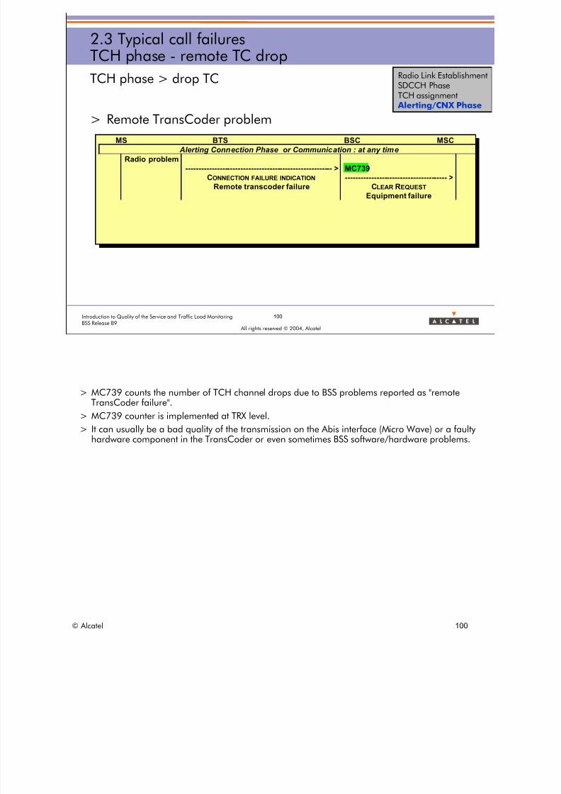
8/12/2019 QOS_B9 (Call Setup)
http://slidepdf.com/reader/full/qosb9-call-setup 100/388
100Introduction to Quality of the Service and Traffic Load MonitoringBSS Release B9
All rights reserved © 2004, Alcatel
2.3 Typical call failuresTCH phase - remote TC drop
TCH phase > drop TC
> Remote TransCoder problem
MS BTS BSC MSC
Alerting Connection Phase or Communication : at any time
Radio problem
-------------------------------------------------------- > MC739
CONNECTION FAILURE INDICATION --------------------------------------- >
Remote transcoder failure CLEAR REQUEST
Equipment failure
Radio Link EstablishmentSDCCH PhaseTCH assignment
Alerting/CNX Phase
> MC739 counts the number of TCH channel drops due to BSS problems reported as "remoteTransCoder failure".
> MC739 counter is implemented at TRX level.
> It can usually be a bad quality of the transmission on the Abis interface (Micro Wave) or a faultyhardware component in the TransCoder or even sometimes BSS software/hardware problems.
© Alcatel 100

8/12/2019 QOS_B9 (Call Setup)
http://slidepdf.com/reader/full/qosb9-call-setup 101/388
101Introduction to Quality of the Service and Traffic Load MonitoringBSS Release B9
All rights reserved © 2004, Alcatel
2.3 Typical call failuresTCH phase - BSS internal drop
TCH phase > drop BSS internal
> Other internal BSS problem (excluding TC)
MS BTS BSC MSC
Alerting Connection Phase or Communication : at any time
MC14C--------------------------------------- >
CLEAR REQUEST
O&M intervention
Radio interface failure
Radio Link EstablishmentSDCCH PhaseTCH assignment
Alerting/CNX Phase
> MC14C counts the number of TCH channel drops due to BSS problems other than the onesreported by the TransCoder.
> A BSS problem can be a BTS/BSC hardware or software failure.
© Alcatel 101

8/12/2019 QOS_B9 (Call Setup)
http://slidepdf.com/reader/full/qosb9-call-setup 102/388
102Introduction to Quality of the Service and Traffic Load MonitoringBSS Release B9
All rights reserved © 2004, Alcatel
2.3 Typical call failuresTCH phase - HO drop
TCH phase > drop HO
> Handover failure
MS BTS BSC MSC
Alerting Connection Phase or Communication : at any time
HOFAILURE WITHOUT REVERSION MC621
--------------------------------------- >
CLEARREQUEST
Radio Interface Message Failure (Alcatel)
Radio Link EstablishmentSDCCH PhaseTCH assignment
Alerting/CNX Phase
> MC621 counts the number of TCH channel drops due to Handover failure. > MC621 counter is implemented at TRX level. > This event is also counted in the set of Handover counters as an Outgoing handover failure
without reversion to the old channel.
© Alcatel 102

8/12/2019 QOS_B9 (Call Setup)
http://slidepdf.com/reader/full/qosb9-call-setup 103/388
103Introduction to Quality of the Service and Traffic Load MonitoringBSS Release B9
All rights reserved © 2004, Alcatel
2.3 Typical call failuresTCH phase - preemption drop
TCH phase > drop preemption
> TCH preemptedMS BTS BSC MSC
Alerting Connection Phase of a callwith priority level pl2 and preemption vulnerability indicator pvi=1
no TCH free
ASSIGNMENT REQUEST
<---------------------------------------
Priority level pl1 > pl2
preemption capability indicator pci=1
MC921C
--------------------------------------- >CLEAR REQUEST
preemption
Radio Link EstablishmentSDCCH PhaseTCH assignment
Alerting/CNX Phase
> MC921C counts the number of TCH channel drops due to preemption for another call to beestablished.
> MC921C counter exists from B7 as linked to the feature Preemption.
© Alcatel 103

8/12/2019 QOS_B9 (Call Setup)
http://slidepdf.com/reader/full/qosb9-call-setup 104/388
104Introduction to Quality of the Service and Traffic Load MonitoringBSS Release B9
All rights reserved © 2004, Alcatel
2.3 Typical call failuresTCH phase - counters
TYPICAL CALL FAILURES: TCH phase counters
TCH connection MC718+MC717A+MC717B
Outgoing HO success MC712
Call drop Drop radio MC736
Drop TC MC739
Drop internal BSS MC14C
Drop HO MC621
Drop preemption MC921C
Normal release unknown
NSS abnormal release unknown
TCH Phase
Outgoing HO success Call drop
TCH connection
Normal release
Call drop radio
Call drop BSS
Call drop HO
Call drop preemption
TC
BSS internal
NSS abnormal release
Radio Link EstablishmentSDCCH PhaseTCH assignment
Alerting/CNX Phase
© Alcatel 104

8/12/2019 QOS_B9 (Call Setup)
http://slidepdf.com/reader/full/qosb9-call-setup 105/388
105Introduction to Quality of the Service and Traffic Load MonitoringBSS Release B9
All rights reserved © 2004, Alcatel
2.3 Typical call failuresTCH phase - call drop rate
TYPICAL CALL FAILURES: TCH phase indicators
> Call drop rate = call drop / RTCH success end
> RTCH success end = RTCH assignment success+ RTCH incoming (HO+DR) success- RTCH outgoing HO
Incoming internal HO+DR
BSS1 BSS2
Incoming external HO+DR
outgoing HO
TCH assignment
Radio Link EstablishmentSDCCH PhaseTCH assignment
Alerting/CNX Phase
> QSCDN = call drop
= drop radio + drop TC + drop internal BSS + drop HO + drop Preemption
= MC736 + MC739 + MC14C + MC621 + MC921C
> TCQHCCN = RTCH success end
= assignment success + incoming (HO+DR) success - outgoing HO
= MC718 + (MC717A+MC717B) - MC712
> As MC718, MC717A, MC717B and MC712 are provided per TRX, the “RTCH success end” indicator (TCAHCCN)can be computed per TRX.
> But since only MC736 (drop radio), MC739 (drop TC) and MC621 (drop HO) are provided per TRX, the “calldrop rate” indicator (QSCDR) can be computed per CELL only.
>
On the other hand the following call drop indicators can be computed per TRX:• call drop radio rate (QSCDRR) = call drop radio / RTCH success end
• call drop HO rate (QSCDHR) = call drop HO / RTCH success end
• call drop TC rate (QSCDBTR) = call drop TC / RTCH success end
> Note:
• MC718 counts the number of successful TCH assignments.
• MC717A counts the number of successful internal DRs.
• MC717B counts the number of successful incoming internal and external (HOs+DR) as well as the numberof intra cell HOs successfully performed.
• MC712 counts the number of successful outgoing internal and external HOs as well as the number of intra
cell HOs successfully performed.
© Alcatel 105

8/12/2019 QOS_B9 (Call Setup)
http://slidepdf.com/reader/full/qosb9-call-setup 106/388
106Introduction to Quality of the Service and Traffic Load MonitoringBSS Release B9
All rights reserved © 2004, Alcatel
2.3 Typical call failuresTCH phase - RTCH drop rate
TYPICAL CALL FAILURES: TCH phase indicators
> RTCH drop rate = call drop / RTCH success begin
> RTCH success begin = RTCH assignment success+ RTCH incoming (HO+DR) success- RTCH intra cell HO success
BSS1 BSS2
Incoming internal HO+DR
TCH assignment
Incoming external HO+DR
outgoing HO
Intra cell HO
Radio Link EstablishmentSDCCH PhaseTCH assignment
Alerting/CNX Phase
> QSCDN = call drop
= drop radio + drop TC + drop internal BSS + drop HO + drop Preemption
= MC736 + MC739 + MC14C + MC621 + MC921C
> TCQHSUBN = RTCH success begin
= assignment success + incoming (HO+DR) success - intra cell HO
= MC718 + (MC717A+MC717B) - MC662
> As MC662 is not provided per TRX, the “RTCH success begin” indicator (TCAHSUBN) cannot becomputed per TRX but per CELL only.
> Therefore all “RTCH drop rate” indicators can be computed per CELL only.
> Note:
• MC662 counts the number of successful TCH intracell HOs.
© Alcatel 106

8/12/2019 QOS_B9 (Call Setup)
http://slidepdf.com/reader/full/qosb9-call-setup 107/388
107Introduction to Quality of the Service and Traffic Load MonitoringBSS Release B9
All rights reserved © 2004, Alcatel
Incoming internal HO+DR
TCH assignment
outgoing HOBSS1 BSS2
Incoming external HO+DR
2.3 Typical call failuresTCH phase - TRX TCH drop rate
TYPICAL CALL FAILURES: TCH phase indicators
> TRX TCH drop rate = call drop / RTCH success
> RTCH success = RTCH assignment success+ RTCH incoming (HO+DR) success
Intra-cell HO
Radio Link EstablishmentSDCCH PhaseTCH assignment
Alerting/CNX Phase
> QSCDN = call drop
= drop radio + drop TC + drop internal BSS + drop HO + drop Preemption
= MC736 + MC739 + MC14C + MC621 + MC921C
> TCAHSUN = RTCH success
= assignment success + incoming (HO+DR) success
= MC718 + (MC717A+MC717B)
> Whereas some call drop rate indicators are defined per TRX and per CELL, TRX RTCH drop rate indicators aredefined at TRX level only.
> As MC718, MC717A, MC717B are provided per TRX, the “RTCH success” indicator (TCAHSUN) can be computedper TRX.
> But since only MC736 (drop radio), MC739 (drop TC) and MC621 (drop HO) are provided per TRX, a global“TRXRTCH drop rate” indicator cannot be provided.
> On the other hand, the following TRX RTCH drop indicators can be computed:
• TRX_RTCH_drop_radio_rate (TCAHCDRTR) = call drop radio / RTCH success
• TRX_RTCH_drop_HO_rate (TCHOCDTR) = call drop HO / RTCH success
• TRX_RTCH_drop_BSS_remote_TC_rate (TCTRTCDTR) = call drop TC / RTCH success
> CAUTION: Intra-cell HO being counted in MC717B and not deduced in the RTCH successcomputation in order to provide the TRX RTCH drop indicators at TRX level then these indicatorsmay be abnormally low (good) if a large amount of intra-cell HOs are performed in the cell(concentric cell, multiband cell).
© Alcatel 107
8/12/2019 QOS_B9 (Call Setup)
http://slidepdf.com/reader/full/qosb9-call-setup 108/388
> Refer to BSS - DEFINITION OF QUALITY OF SERVICE INDICATORS
> call drop indicators: all of them are available per CELL only and some of them per TRX
• GLOBAL Quality of service INDICATORS > Call Statistics > Call drop
– QSCDR: call drop rate (Global): CELL
– QSCDRR: call drop rate due to radio: CELL + TRX
– QSCDBIR: call drop rate due to BSS internal problem: CELL
– QSCDBTR: call drop rate due to TransCoder reported problem: CELL + TRX
– QSCDHR: call drop rate due to HO failure: CELL + TRX
– QSCDPR: call drop rate due to preemption: CELL
> RTCH drop indicators: all of them are available per CELL only
• GLOBAL Quality of service INDICATORS > RTCH > Established phase
– QSTCCDR: RTCH drop rate
– TCAHCDRR: RTCH drop rate due to radio problem
– TCTRICDBR: RTCH drop rate due to BSS internal problem
– TCTRTCDR: RTCH drop rate due to TransCoder reported problem
– TCHOCDR: RTCH drop rate due to HO failure
– TCPPCDR: RTCH drop rate due to preemption
> TRX TCH drop indicators: all of them are available per TRX only
• GLOBAL Quality of service INDICATORS > RTCH > Established phase
– TCAHCDRTR: TRX TCH drop rate due to radio problem
– TCTRTCDTR: TRX TCH drop rate due to TransCoder reported problem
– TCHOCDTR: TRX TCH drop rate due to HO failure
© Alcatel 108
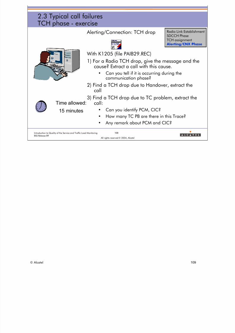
8/12/2019 QOS_B9 (Call Setup)
http://slidepdf.com/reader/full/qosb9-call-setup 109/388
109Introduction to Quality of the Service and Traffic Load MonitoringBSS Release B9
All rights reserved © 2004, Alcatel
2.3 Typical call failuresTCH phase - exercise
Alerting/Connection: TCH drop
With K1205 (file PAIB29.REC)
1) For a Radio TCH drop, give the message and thecause? Extract a call with this cause.
• Can you tell if it is occurring during thecommunication phase?
2) Find a TCH drop due to Handover, extract thecall
3) Find a TCH drop due to TC problem, extract thecall:
• Can you identify PCM, CIC?
• How many TC PB are there in this Trace?
• Any remark about PCM and CIC?
Time allowed:
15 minutes
Radio Link EstablishmentSDCCH PhaseTCH assignment
Alerting/CNX Phase
© Alcatel 109

8/12/2019 QOS_B9 (Call Setup)
http://slidepdf.com/reader/full/qosb9-call-setup 110/388
110Introduction to Quality of the Service and Traffic Load MonitoringBSS Release B9
All rights reserved © 2004, Alcatel
2.3 Typical call failuressummary
TYPICAL CALL FAILURES: summary
call stage A interface causefield related problem
radio inkestablishment
no message - SDCCH congestion- radio problem-Dummyrach
SDCCH phase ClearRequest - radio interfacefailure- radio interfacefailure- O&M intervention
- radioproblem- BSS system HW/SWpb-recovery/operator
TCHassignment Assignment Failure - no radio esourceavalaible- Radio InterfaceFailure
- TCH congestion- Radioproblem
Alerting/connectioncallestablished
Clear Request - radio interfacefailure- radio interface messageailure-equipmentfailure
- O&M intervention- radio interfacefailure-preemption
- radioproblem- HO ailure w/oreversion- Transcoderfailure-operatoraction/recovery
- BSS system HW/SWpb-preemption
LAPD counter to analyze the cause of call establishment failures
Radio Link EstablishmentSDCCH PhaseTCH assignment Alerting/CNX Phase
> When the BSC is congested on the downlink, some messages are discarded. This may result forexample in call establishment failures, loss of paging messages or delay in handoverprocedures.
A LapD counter that indicates the time a LapD link is congested is created to analyze the causeof a degraded quality of service. This counter is implemented in type 7 and thus is onlyavailable in a detailed measurement campaign.
• Counter: L1.18: TIME_LAPD_CONG
• Definition: Time in seconds during which the LapD link is congested in transmission in theBSC.
© Alcatel 110

8/12/2019 QOS_B9 (Call Setup)
http://slidepdf.com/reader/full/qosb9-call-setup 111/388
All rights reserved © 2004, Alcatel
2 GLOBAL INDICATORS
2.4 Description of global indicators
© Alcatel 111

8/12/2019 QOS_B9 (Call Setup)
http://slidepdf.com/reader/full/qosb9-call-setup 112/388
112Introduction to Quality of the Service and Traffic Load MonitoringBSS Release B9
All rights reserved © 2004, Alcatel
2.4 Description of global indicatorsrecall
> Global Indicators are
• A set of indicators selected by Alcatel
• Useful to monitor the overall network
> What are the user and or system impacts if a GI (GlobalIndicator) is bad?
© Alcatel 112

8/12/2019 QOS_B9 (Call Setup)
http://slidepdf.com/reader/full/qosb9-call-setup 113/388
2.4 Description of global indicatorsSDCCH congestion rate
INDICATOR
(G)
SDCCH ASSIGN CONG FAIL RATE
DEFINITION Rate of SDCCH not allocated during radio link establishment procedure due to congestion on the
Air interface
FORMULA Σcell
(MC04) / SDCCH ASSIGN REQUESTS
THRESHOLD > 5%
COMMENT Check SDCCH Erlang : if not critical, SDCCH availability/allocation problem, or HO access on a
nearby cell side effect or interference on the carrier handling SDCCH (the last 2 can lead to high
rate of « phantom RACH »)
REF NAME SDNACGR UNIT %
> SDCCH CONGESTION rate: may have impact for subscriber
• Call setup failure only after 3 subsequent congestions
• If not, only some extra delay for call establishment
– (less than 1 second) without immediate_assign_reject
– Can be longer with reject (but usually short values are used for callrequest)
113Introduction to Quality of the Service and Traffic Load MonitoringBSS Release B9
All rights reserved © 2004, Alcatel
INDICATOR SDCCH ASSIGN REQUESTS
DEFINITION Number of SDCCH seizure requests during radio link establishment procedureFORMULA Σcell (MC148 + MC04)
THRESHOLD
COMMENT This includes requests rejected due to congestion on SDCCHREF NAME SDNARQN UNIT Number
> (G) means that the indicator is Global, i.e. it is important to provide it at a Network level.
© Alcatel 113

8/12/2019 QOS_B9 (Call Setup)
http://slidepdf.com/reader/full/qosb9-call-setup 114/388
114Introduction to Quality of the Service and Traffic Load MonitoringBSS Release B9
All rights reserved © 2004, Alcatel
2.4 Description of global indicatorsSDCCH congestion rate
SDCCH CONGESTION rate
SDNARQNSDCGMR
> Refer to BSS - DEFINITION OF QUALITY OF SERVICE INDICATORS
• GLOBAL Quality of service INDICATORS > SDCCH > Assignment phase
– SDNACGR: SDCCH assignment failure rate due to congestion (Global)
© Alcatel 114
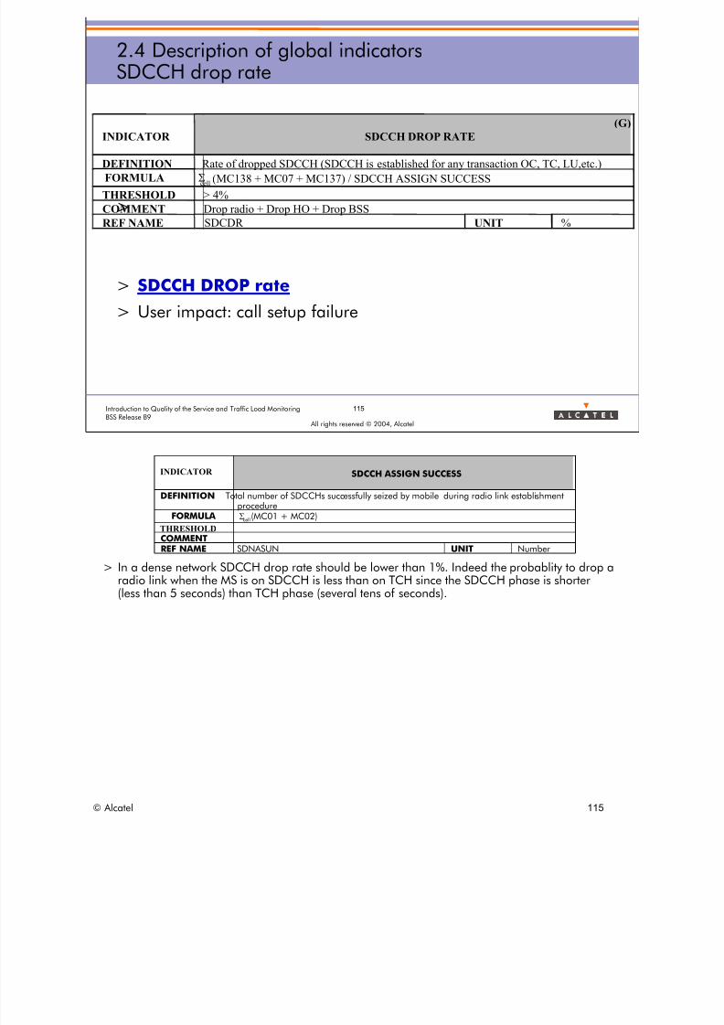
8/12/2019 QOS_B9 (Call Setup)
http://slidepdf.com/reader/full/qosb9-call-setup 115/388
115Introduction to Quality of the Service and Traffic Load MonitoringBSS Release B9
All rights reserved © 2004, Alcatel
2.4 Description of global indicatorsSDCCH drop rate
>
> SDCCH DROP rate> User impact: call setup failure
INDICATOR
(G)
SDCCH DROP RATE
DEFINITION Rate of dropped SDCCH (SDCCH is established for any transaction OC, TC, LU,etc.)
FORMULA Σcell (MC138 + MC07 + MC137) / SDCCH ASSIGN SUCCESS
THRESHOLD > 4%
COMMENT Drop radio + Drop HO + Drop BSS
REF NAME SDCDR UNIT %
INDICATOR
DEFINITION To
SDCCH ASSIGN SUCCESS
tal number of SDCCHs successfully seized by mobile during radio link establishmentprocedure
FORMULA Σcell (MC01 + MC02)
THRESHOLDCOMMENTREF NAME SDNASUN UNIT Number
> In a dense network SDCCH drop rate should be lower than 1%. Indeed the probablity to drop aradio link when the MS is on SDCCH is less than on TCH since the SDCCH phase is shorter(less than 5 seconds) than TCH phase (several tens of seconds).
© Alcatel 115
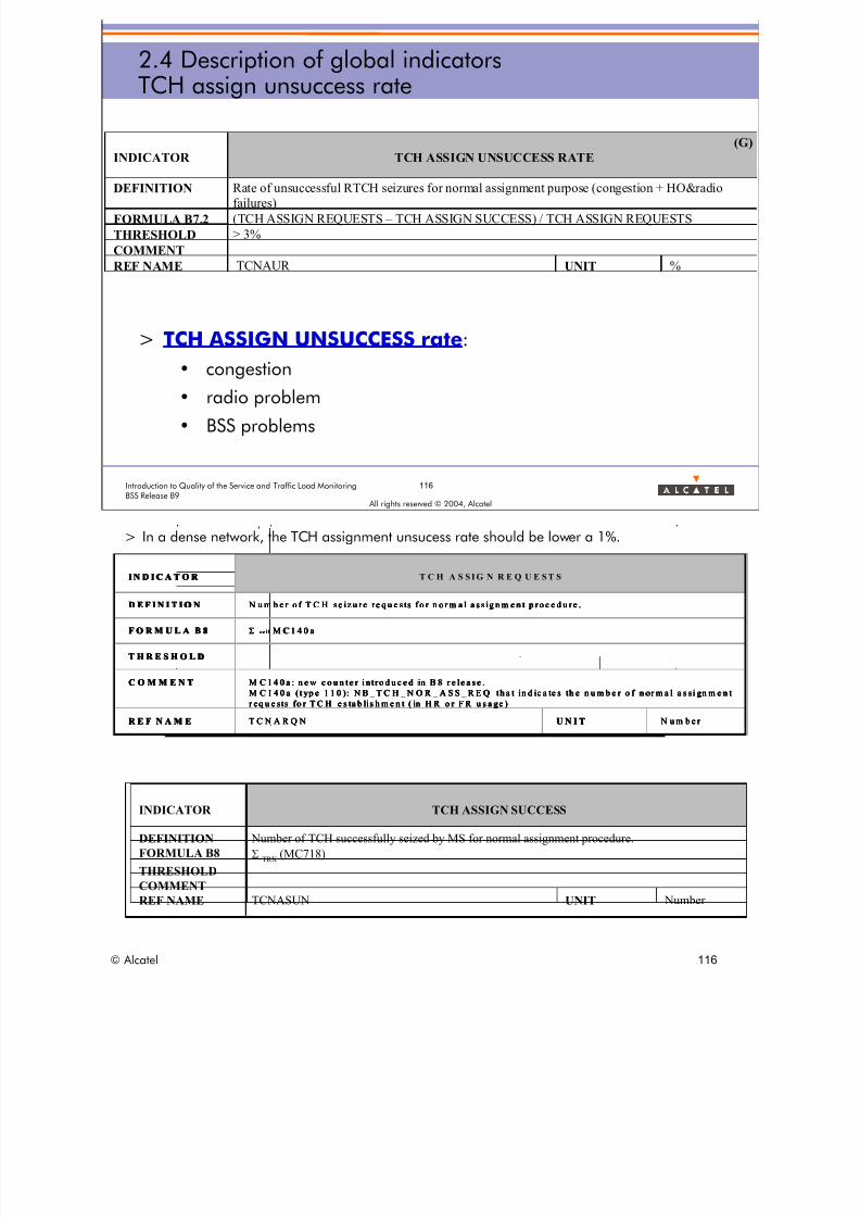
8/12/2019 QOS_B9 (Call Setup)
http://slidepdf.com/reader/full/qosb9-call-setup 116/388
T C H S S I G N R E Q U E S T SC H S S I G N R E Q U E S T SC H S S I G N R E Q U E S T SC H S S I G N R E Q U E S T S
2.4 Description of global indicatorsTCH assign unsuccess rate
INDICATOR
(G)
TCH ASSIGN UNSUCCESS RATE
DEFINITION Rate of unsuccessful RTCH seizures for normal assignment purpose (congestion + HO&radio
failures)
FORMULA B7.2 (TCH ASSIGN REQUESTS – TCH ASSIGN SUCCESS) / TCH ASSIGN REQUESTS
THRESHOLD > 3%
COMMENT
REF NAME TCNAUR UNIT %
> TCH ASSIGN UNSUCCESS rate:• congestion
• radio problem
• BSS problems
116Introduction to Quality of the Service and Traffic Load MonitoringBSS Release B9
All rights reserved © 2004, Alcatel
> In a dense network, the TCH assignment unsucess rate should be lower a 1%.
I N D I C A T O R
D E F I N I T I O N N u m b e r o f T C H s e iz u r e r e q u e s ts f o r n o r m a l a s s i g n m e n t p r o c e d u re .
F O R M U L A B 8 Σ c e l l M C 1 4 0 a
T H R E S H O L D
C O M M E N T M C 1 4 0 a : n e w c o u n t e r i n tr o d u c e d i n B 8 r e l e a s e .
M C 1 4 0 a ( ty p e 1 1 0 ) : N B _ T C H _ N O R _ A S S _ R E Q t ha t in d ic a te s t h e n u m b e r o f n o r m a l a s s i gn m e n t
r e q u e s ts f o r T C H e s t a b li s h m e n t ( in H R o r F R u s a g e )
R E F N A M E T C N A R Q N U N I T N u m b e r
I N
s f o r n o r m a l a s s ig n m e n t p r o c e d u r e .
R M U L A B 8 ll M C 1 4 0 a
E S H O L D
N T 1 4 0 a : n e w c o u n te r in tr o d u c e d in B 8 r e l e a se .
M C 1 4 0 a ( t yp e 1 1 0 ): N B _ T C H _ N O R _ A S S _ R E Q th a t in d ic a te s th e n u m b e r o f n or m a l a s si gn m e n t
r eq u e sts fo r T C H e s ta b li s h m e n t ( in H R o r F R u s a ge )
N A M E N A R Q N b e r
I NI N D I C A T O R
D E F I N I T I O N N u m b e r o f T C H s e iz u r e r e q u e s t
F O Σ ce
T H R
C O M M E M C
R E F T C U N I T N u m
D I C A T O R D I C A T O R T C H A S S I G N R E Q U E S T S
D E F I N I T I O ND E F I N I T I O N N u m b e r o f T C H s e iz u r e r e q u e s ts f o r n o r m a l a s s i g n m e n t p r o c e d u re . N u m b e r o f T C H s e iz u r e r e q u e s ts f o r n o r m a l a s s i g n m e n t p r o c e d u re .
F O R M U L A B 8F O R M U L A B 8 Σ c e l l M C 1 4 0 aΣ c e l l M C 1 4 0 a
T H R E S H O L DT H R E S H O L D
C O M M E N TC O M M E N T M C 1 4 0 a : n e w c o u n t e r i nt ro d u c e d in B 8 r e le a s e .
M C 1 4 0 a ( t yp e 1 1 0 ): N B _ T C H _ N O R _ A S S _ R E Q th a t in d ic a te s th e n u m b e r o f n or m a l a s si gn m e n t
r eq u e sts fo r T C H e s ta b li s h m e n t ( in H R o r F R u s a ge )
M C 1 4 0 a : n e w c o u n t e r i nt ro d u c e d in B 8 r e le a s e .
M C 1 4 0 a ( t yp e 1 1 0 ): N B _ T C H _ N O R _ A S S _ R E Q th a t in d ic a te s th e n u m b e r o f n or m a l a s si gn m e n t
r eq u e sts fo r T C H e s ta b li s h m e n t ( in H R o r F R u s a ge )
R E F N A M ER E F N A M E T C N A R Q NT C N A R Q N U N I TU N I T N u m b e r N u m b e r
INDICATOR TCH ASSIGN SUCCESS
DEFINITION Number of TCH successfully seized by MS for normal assignment procedure.
FORMULA B8 ΣTRX
(MC718)
THRESHOLDCOMMENT
REF NAME TCNASUN UNIT Number
© Alcatel 116

8/12/2019 QOS_B9 (Call Setup)
http://slidepdf.com/reader/full/qosb9-call-setup 117/388
117Introduction to Quality of the Service and Traffic Load MonitoringBSS Release B9
All rights reserved © 2004, Alcatel
2.4 Description of global indicatorsGlobal radio congestion level
> GLOBAL RADIO CONGESTION LEVEL (TCH congestion rate)
• Subscriber impact: call setup failure
• More a management indicator: % of network which has congestion
INDICATOR
(G)
GLOBAL RADIO CONGESTION LEVEL
DEFINITION Global radio congestion level : number or rate of cells recurrently congested
FORMULA COUNT_OF_CELLS (AVERAGE (MAX (TCH ASSIGN FAIL CONG RATE)) > 2%))
THRESHOLD According to operator
COMMENT This indicator reports the global radio congestion rate on the network. We define a specific
indicator counting the number of cells that are in congestion in a recurrent manner.
MAX (TCH ASSIGN FAIL CONG RATE) : is the peak of failures due to congestion observed
during the period (the day normally). See the definition of TCH ASSIGN FAIL CONG RATE in the
Quality of Service chapter)
AVERAGE: is an averaging function of the blocking rate over the selected period, that is over BH
of days for a week, or over BH of weeks for a month
COUNT_OF_CELL: is a function counting the number of cells for which condition between () is
respected.
The number of cells can be used as indicator, or the rate of cells over the total number of cells in thenetwork or area.
REF NAME QSCGR UNIT Number
> This counter intends to give a measurement of the TCH congestion of the whole network.
> It is implemented on the Alcatel tools but other indicators can be defined.
© Alcatel 117

8/12/2019 QOS_B9 (Call Setup)
http://slidepdf.com/reader/full/qosb9-call-setup 118/388
118Introduction to Quality of the Service and Traffic Load MonitoringBSS Release B9
All rights reserved © 2004, Alcatel
2.4 Description of global indicatorsCall drop rate
> CALL DROP rate: The most important indicator• Used with call setup success rate to compare PLMN (GSM and
other one)
• Subscribers impact: call drop!!
INDICATOR(G)
CALL DROP RATE
DEFINITION radio+ HO +Rate of dropped calls (system + preemption) over the total amount of calls with a
successful end
FORMULA Scell (MC621 + MC14c + MC736 + MC739 + MC921c) / TCH SUCCESS END
THRESHOLD > 4%COMMENT Drop system + Drop radio + Drop HO + Droppreemption
TCH drops occurring after successful assignment but before speech connection are considered as
call drops even if from the customer point of view it is a call setup failure
MC739, MC736 and MC621 derive from B6 counters C139, C136 and C21. These new countersare per TRX
MC921c was new in B7.2REF NAME QSCDR UNIT %
> In a dense network, the Call Drop Rate should be lower than 2%. It should even go down to 1% or less in case Slow FrequencyHopping is used.
> The RTCH drop rate is defined below:
INDICATOR GLOBAL TCH DROP
DEFINITION Rate of TCHs dropped (system + radio + handover + preemption) over the total amount ofcalls established in the cell
FORMULA Σcell(MC14c + MC739 + MC736 + MC621+ MC921c) / TCH SUCCESS BEGIN
THRESHOLD
COMMENT D
M
> 3%rop System + Drop radio + Drop HO + Drop preemption
Indicator relevant at cell level mostly.C739, MC736 and MC621 derive from B6 counters C139, C136 and C21. These newcounters are per TRXMC921c is new in B7.2
REF NAME QSTCCDR UNIT %> The TRX TCH drop radio rate is defined below:
INDICATOR TRX TCH DROP RADIO RATE
DEFINITION Rate of TCHs dropped due to radio problems, per TRXFORMULA (MC736) / TCH SUCCESS
THRESHOLD > 3%COMMENT New from B7
MC736 derives from B6 counters C136. This new counter in B7 is per TRX.
Indicator only per TRX because intracell handovers are taken into accountREF NAME TCAHCDRTR UNIT %
© Alcatel 118

8/12/2019 QOS_B9 (Call Setup)
http://slidepdf.com/reader/full/qosb9-call-setup 119/388
119Introduction to Quality of the Service and Traffic Load MonitoringBSS Release B9
All rights reserved © 2004, Alcatel
2.4 Description of global indicatorsCall setup success rate
> CALL SETUP SUCCESS rate: the second most important indicator
• Used to compare PLMN• Subscriber: call not established at the first attempt
> Beware: call setup failures due to a lack of coverage are not taken intoaccount in this indicator!!
– No way to quantify them (as there is no initial access)
INDICATOR(G)
CALL SETUP SUCCESS RATE (BSS view)
DEFINITION Rate of calls going until TCH successful assignment, that is not interrupted by SDCCH DROP
neither by Assignment failures
FORMULA (1 – ( SDCCH DROP / SDCCH ASSIGN SUCCESS ) ) * (1 TCH ASSIGN UNSUCCESS RATE)
THRESHOLD > 95%COMMENT SDCCH assignment failures are not considered in CSSR as :
· ghost (spurious) RACH cannot be discriminated from a real access failure· effect of re-attempts performed autonomously by the MS cannot be quantified
REF NAME QSCSSR UNIT %
> Ghost Racks which correspond to a valid establishment cause are not identified by the BSS.Therefore they can lead to a high SDCCH assignment failure rate if they are too numerous.
> As the end user is not impacted by this phenomenon if no SDCCH congestion is induced, theSDCCH assignment phase is not considered in the computation of the Call Setup Success rateprovided by Alcatel tools.
> In a dense network, the Call Setup Success Rate should be greater than 98%.
> The SDCCH congestion rate should also be considered to have a complete picture of Call Setupefficiency.
© Alcatel 119
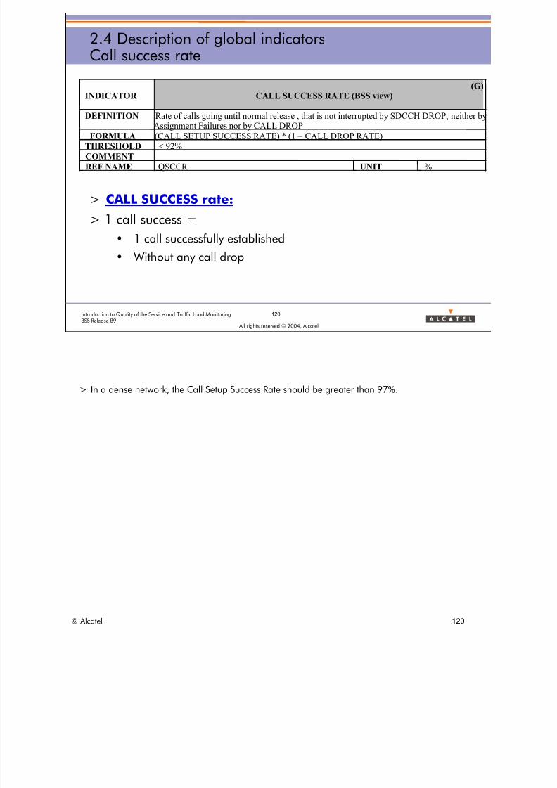
8/12/2019 QOS_B9 (Call Setup)
http://slidepdf.com/reader/full/qosb9-call-setup 120/388
2.4 Description of global indicatorsCall success rate
INDICATOR(G)
CALL SUCCESS RATE (BSS view)
DEFINITION Rate of calls going until normal release , that is not interrupted by SDCCH DROP, neither byAssignment Failures nor by CALL DROP
FORMULA (CALL SETUP SUCCESS RATE) * (1 – CALL DROP RATE)THRESHOLD < 92%
COMMENT
REF NAME QSCCR UNIT %
> CALL SUCCESS rate: > 1 call success =
• 1 call successfully established
• Without any call drop
Introduction to Quality of the Service and Traffic Load Monitoring 120
BSS Release B9 All rights reserved © 2004, Alcatel
> In a dense network, the Call Setup Success Rate should be greater than 97%.
© Alcatel 120

8/12/2019 QOS_B9 (Call Setup)
http://slidepdf.com/reader/full/qosb9-call-setup 121/388
121Introduction to Quality of the Service and Traffic Load MonitoringBSS Release B9
All rights reserved © 2004, Alcatel
2.4 Description of global indicatorsCall (setup) success rate
CALL SETUP SUCCESS rateCALL SUCCESS rate
TCAHSUNQSCCRQSCSSR
> Refer to BSS - DEFINITION OF QUALITY OF SERVICE INDICATORS
• GLOBAL Quality of service INDICATORS > Call statistics > Call success
– QSCSSR: Call setup success rate (Global)
– QSCCR: Call success rate (Global)
© Alcatel 121

8/12/2019 QOS_B9 (Call Setup)
http://slidepdf.com/reader/full/qosb9-call-setup 122/388
122Introduction to Quality of the Service and Traffic Load MonitoringBSS Release B9
All rights reserved © 2004, Alcatel
2.4 Description of global indicatorsHandover cause distribution
> Indicator aiming at measuring the efficiency of planning /optimization
INDICATOR
(G)
HO CAUSE DISTRIBUTION
DEFINITION Distribution of Handover attempts by cause X : UL/DL Qual, UL/DL Lev, UL/DL Interference,
Distance, Better Cell, Interband, Micro cells HO, Concentric cell, Traffic, AMR, TFO causes.FORMULA B7.2 Σcell
(MC67w or MC785x or MC586y or MC10zz or MC447 or MC461)
Σcell
(MC67all + MC785all + MC586all + MC10all + MC447 + MC461)
MC67all = MC671+MC672+MC673+MC674+MC675+MC676+MC677+MC678+MC679
+MC670
MC785all = MC785a + MC785d + MC785e + MC785f (microcell)
MC586all = MC586a + MC586b + MC586c (concentric)
MC10all = MC1040 + MC1044 + MC1050
THRESHOLD Quality DL > 10%, Qual UL > 10%, Level UL > 20%, Level DL > 20%
Interf UL > 5%, Interf DL > 5%, Better Cell < 30%
COMMENTREF NAME HCSTBPBR, HCCCELVDR, HCCCELVUR, HCCCBCPR,
HCSTEDIR, HCSTEIFDR, HCSTELVDR, HCSTEQLDR,
HCSTBDRR, HCMBBCPR, HCMCEBSR, HCMCELVDR,
HCMCBCPR, HCMCELVUR, HCSTEMIR, HCSTEIFUR,
HCSTELVUR, HCSTEQLUR, HCSTAMR, HCSTBTFR
UNIT %
© Alcatel 122

8/12/2019 QOS_B9 (Call Setup)
http://slidepdf.com/reader/full/qosb9-call-setup 123/388
123Introduction to Quality of the Service and Traffic Load MonitoringBSS Release B9
All rights reserved © 2004, Alcatel
2.4 Description of global indicatorsHandover standard cause distribution
> Indicator aiming at measuring the efficiency of planning / optimization
> Interesting for comparing HO distribution after concentric or micro cellimplementation
INDICATOR
(G)
DISTRIBUTION HO CAUSE STANDARD
DEFINITION Distribution of Handover attempts by standard cause : Power Budget, quality too low, level too low,
high interference and MS-BTS distance too long.
FORMULA B7.2
Σcell ( (MC67x) / GLOBAL HO CAUSE STANDARD)
MC67x = MC670 or MC672 or MC671 or MC673 or MC676 or MC677 or MC678 or MC674 or
(MC670+MC672) or (MC671+MC673) or (MC676+M677)
THRESHOLD
COMMENT
REF NAME HCSTEIFDSR, HCSTEIFUSR, HCSTEIFSR, HCSTELVDSR,
HCSTELVUSR, HCSTELVSR, HCSTEQLDSR,
HCSTEQLUSR, HCSTEQLSR, HCSTBPBSR, HCSTEDISR
UNIT %
> The Global HO cause standard indicator is defined as below:
• where:
– MC670: Number of handover attempts cause 2: "uplink quality too low"
– MC672: Number of handover attempts cause 4: ”downlink quality too low"
– MC671: Number of handover attempts cause 3: "uplink level too low"
– MC673: Number of handover attempts cause 5: "downlink level too low"
– MC676: Number of handover attempts cause 15: "too high uplink interferencelevel"
– MC677: Number of handover attempts cause 16: "too high downlink interferencelevel"
– MC678: Number of handover attempts cause 12: "too low power budget"
– MC674: Number of handover attempts cause 6: "MS-BTS distance too long"
© Alcatel 123
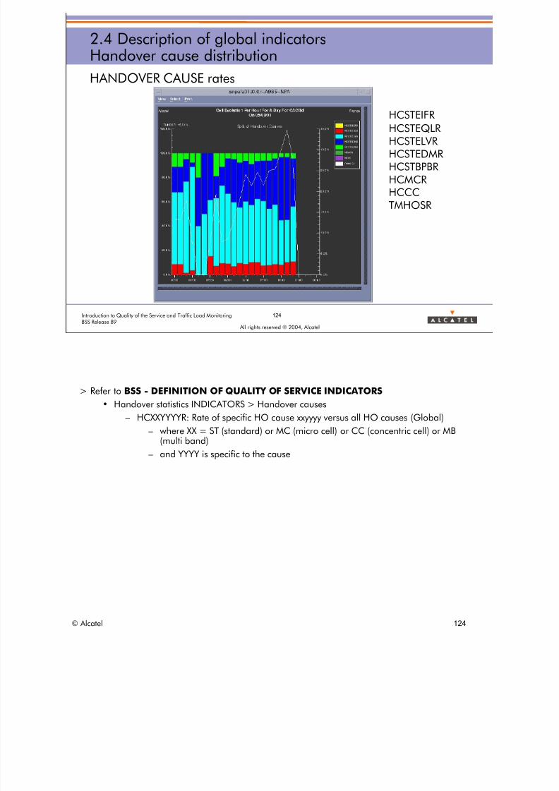
8/12/2019 QOS_B9 (Call Setup)
http://slidepdf.com/reader/full/qosb9-call-setup 124/388
124Introduction to Quality of the Service and Traffic Load MonitoringBSS Release B9
All rights reserved © 2004, Alcatel
2.4 Description of global indicatorsHandover cause distribution
HANDOVER CAUSE rates
HCSTEIFRHCSTEQLRHCSTELVRHCSTEDMRHCSTBPBRHCMCRHCCCTMHOSR
> Refer to BSS - DEFINITION OF QUALITY OF SERVICE INDICATORS
• Handover statistics INDICATORS > Handover causes
– HCXXYYYYR: Rate of specific HO cause xxyyyy versus all HO causes (Global)
– where XX = ST (standard) or MC (micro cell) or CC (concentric cell) or MB(multi band)
– and YYYY is specific to the cause
© Alcatel 124

8/12/2019 QOS_B9 (Call Setup)
http://slidepdf.com/reader/full/qosb9-call-setup 125/388
125Introduction to Quality of the Service and Traffic Load MonitoringBSS Release B9
All rights reserved © 2004, Alcatel
2.4 Description of global indicatorsOutgoing handover success rate
> Global success rate of Outgoing HO
> Success rate of execution of Outgoing HO
INDICATOR
(G)
OUTGOING HO SUCCESS RATE
DEFINITION Rate of successful outgoing external and internal intercell SDCCH and TCH handovers
FORMULA B7.2 Σcell (MC646 + MC656) / Σcell (MC645a + MC655a)
THRESHOLD < 90%
COMMENT This indicator includes preparation and execution.
REF NAME HOORSUR UNIT %
INDICATOR
(G)
EFFICIENCY OF OUTGOING HANDOVER EXECUTION
DEFINITION Rate of successful outgoing external and internalintercell SDCCH and TCHhandovers
FORMULA Σcell (MC646 + MC656) /Σcell (MC650 + MC660)
THRESHOLD < 90%
COMMENT This indicator takes into account HO execution only (not ho preparation).
REF NAME HOOREFR UNIT %
> Global Outgoing HO success rate: represents the global efficiency ot theoutgoing handovers performed from one cell to any of its neighboring cells (sameBSS or not).
> Efficiency of Outgoing HO execution: represents the efficiency of the channelchange procedure during outgoing handovers performed from one cell to any of
its neighboring cells (same BSS or not). It does not take into account the HOfailures that can occur during the preparation phase when the new channel isbeing selected and activated.
> From B7 MC645A replaces MC645 of B6.
© Alcatel 125

8/12/2019 QOS_B9 (Call Setup)
http://slidepdf.com/reader/full/qosb9-call-setup 126/388
2.4 Description of global indicatorsIncoming handover success rate
> Global success rate of Incoming HO INDICATOR
DEFINITION
(G)
INCOMING HANDOVER SUCCESS RATE
Rate of successful incoming external and internalintercell SDCCH and TCHhandovers.
FORMULA Σcell(MC642 + MC652) /Σcell(MC820 + MC830)
THRESHOLD < 90%
COMMENT
REF NAME HOIRSUR UNIT %
> Success rate of execution of Incoming HO INDICATOR
DEFINITION
(G)
EFFICIENCY OF INCOMING HANDOVERS
Rate of successful incoming external and internalintercell SDCCH and TCH HOs
FORMULA Σcell (MC642 + MC652) /Σcell(MC821 + MC831)
THRESHOLD < 90%
COMMENT Excluding congestion failures and BSS preparation failures from requests.
REF NAME HOIREFR UNIT %
Introduction to Quality of the Service and Traffic Load Monitoring 126
BSS Release B9 All rights reserved © 2004, Alcatel
> Global Incoming HO success rate: represents the global efficiency of the incoming handoversperformed to one cell from any of its neighboring cells (same BSS or not).
> Efficiency of Incoming HO execution: represents the efficiency of the channel change procedureduring incoming handovers performed to one cell from any of its neighboring cells (same BSSor not). It does not take into account the HO failures that can occur during the preparationphase when the new channel is being selected and activated.
© Alcatel 126

8/12/2019 QOS_B9 (Call Setup)
http://slidepdf.com/reader/full/qosb9-call-setup 127/388
2.4 Description of global indicatorsCall quality factor absolute
INDICATOR(G)
CELL QUALITY FACTOR ABSOLUTE
DEFINITION Indicator summarizing the cell behavior and allowing the operator to sort out cell forinvestigation.This indicator is based on failure events. For each part of the indicator,twothresholds are used: Topt and TQoS. TQoS is the QoS warning threshold (e.g. above
belowthe threshold, a warning is generated on the cell. Topt + TQoS is the optimal valueor
that should be acheived. Each part as a weighting factor (WF) according to theimpact on the subscriber’s point of view.
FORMULA ((1 – SDCCH CONGESTION rate) - TQoS)/ Topt * WF+ (CALL SETUP SUCCESS rate - TQoS)/ Topt *WF
+ ((1 – CALL DROP rate - TQoS)/ Topt * WF+ (OUTGOING HO SUCCESS rate - TQoS)/ Topt * WF+ ((1 – HO QUALITY rate - TQoS)/ Topt * WF
THRESHOLD SDCCH CONGESTION rate : TQoS= 0.97, Topt= 0.03, WF = 0.1CALL SETUP SUCCESS rate : TQoS= 0.9, Topt= 0.09, WF = 0.2CALL DROP rate : TQoS= 0.96, Topt= 0.04, WF = 0.3
OUTGOING HO SUCCESS rate : TQoS= 0.85, Topt= 0.12, WF = 0.15HO QUALITY rate : TQoS= 0.85, Topt= 0.1, WF = 0.25
COMMENTREF NAME QSCQAR UNIT %
investigation. This indicator is based on failure events. For each part of the indicator, two
> The highest, the best is the cell
> But the traffic handled is not taken into accountIntroduction to Quality of the Service and Traffic Load Monitoring 127
BSS Release B9 All rights reserved © 2004, Alcatel
> This counter intends to compute for every cell of the network a global indicator taking intoaccount the major causes of bad Quality of Service.
> Each cause is weighted according to the impact on the end user.
© Alcatel 127
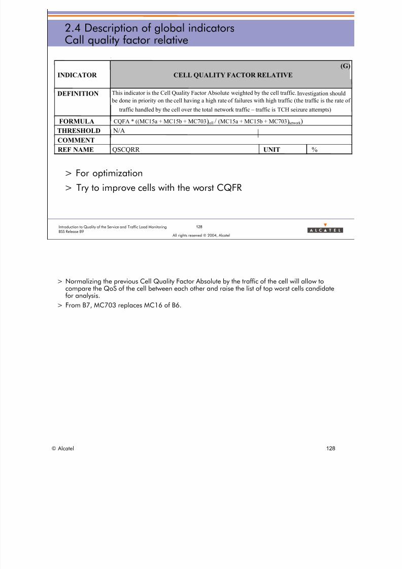
8/12/2019 QOS_B9 (Call Setup)
http://slidepdf.com/reader/full/qosb9-call-setup 128/388
128Introduction to Quality of the Service and Traffic Load MonitoringBSS Release B9
All rights reserved © 2004, Alcatel
2.4 Description of global indicatorsCall quality factor relative
> For optimization
> Try to improve cells with the worst CQFR
INDICATOR
(G)
CELL QUALITY FACTOR RELATIVE
DEFINITION This indicator is the Cell Quality Factor Absolute weighted by the cell traffic.Investigation should
be done in priority on the cell having a high rate of failures with high traffic (the traffic is the rate of
traffic handled by the cell over the total network traffic – traffic is TCH seizure attempts)
FORMULA CQFA * ((MC15a + MC15b + MC703)cell / (MC15a + MC15b + MC703)network )
THRESHOLD N/A
COMMENT
REF NAME QSCQRR UNIT %
> Normalizing the previous Cell Quality Factor Absolute by the traffic of the cell will allow tocompare the QoS of the cell between each other and raise the list of top worst cells candidatefor analysis.
> From B7, MC703 replaces MC16 of B6.
© Alcatel 128

8/12/2019 QOS_B9 (Call Setup)
http://slidepdf.com/reader/full/qosb9-call-setup 129/388
129Introduction to Quality of the Service and Traffic Load MonitoringBSS Release B9
All rights reserved © 2004, Alcatel
2.4 Description of global indicatorsNetwork TCH availability
> Management indicator, maintenance oriented, assessing• Quantity of stability problems
• Reaction time to problems
INDICATOR
(G)
NETWORK (TCH) AVAILABILITY
DEFINITION Rate of TCHs able to carry traffic (upon the total number of traffic channels)
FORMULA (Σcell
(MC250) / #Available TCH)
THRESHOLD < 95%
COMMENT #Available TCH : according to channel configuration
REF NAME TCAVAR UNIT %
© Alcatel 129

8/12/2019 QOS_B9 (Call Setup)
http://slidepdf.com/reader/full/qosb9-call-setup 130/388
130Introduction to Quality of the Service and Traffic Load MonitoringBSS Release B9
All rights reserved © 2004, Alcatel
2.4 Description of global indicatorsExercise
Time allowed:
10 minutes
Indicator value OK ? Impact
1- SDCCH congestion 10% NOK difficulties to establish call
2- Call drop 5%3- Call success 95%
4- Efficiency of outgoing HO 91%
5- Network TCH availability 94%
6- TCH assignment failure 2,4 %
7- Call drop 2,3 %
8- SDCCH drop 2%
9- HO cause distribution
(ratio of better cell)
45%
10- Call success 88%
11- SDCCH drop 1%
© Alcatel 130

8/12/2019 QOS_B9 (Call Setup)
http://slidepdf.com/reader/full/qosb9-call-setup 131/388
All rights reserved © 2004, Alcatel
2 GLOBAL INDICATORS
2.5 Traps and restrictions of globalindicators
© Alcatel 131

8/12/2019 QOS_B9 (Call Setup)
http://slidepdf.com/reader/full/qosb9-call-setup 132/388
132Introduction to Quality of the Service and Traffic Load MonitoringBSS Release B9
All rights reserved © 2004, Alcatel
2.5 Traps and restrictions of global indicatorsObjective
> Beware of traps and restrictions about some global indicators
> So as to be able to provide a reliable interpretation
© Alcatel 132

8/12/2019 QOS_B9 (Call Setup)
http://slidepdf.com/reader/full/qosb9-call-setup 133/388
133Introduction to Quality of the Service and Traffic Load MonitoringBSS Release B9
All rights reserved © 2004, Alcatel
2.5 Traps and restrictions of global indicatorsCall set-up success rate / Call drop rate
> CALL SETUP SUCCESS
• The radio link establishment failure is not taken into account,because:
– most of failures during RLE are due to ghost RACH
– the MS is attempting MAX_RETRANS+1 times before giving up
– difficult to assess subscriber's impact, anyhow very low
> CALL DROP
• For BSS, the last stage is considered as established, although it is
not the cause from a user point of view
• If a TCH drop occurs during this phase
– for the user, it is a setup failure
– for the OMC-R indicators, counted as a call drop
© Alcatel 133

8/12/2019 QOS_B9 (Call Setup)
http://slidepdf.com/reader/full/qosb9-call-setup 134/388
2.5 Traps and restrictions of global indicatorsCall duration
IMPACT OF CALL DURATION
> The longest a call is, the highest the risk to have a drop is
> If statistics are done on abnormally long or short calls, the resultcan be less accurate
> Typical case: drive test
> Typical call duration: 80/90 seconds in most of European
countries
134Introduction to Quality of the Service and Traffic Load MonitoringBSS Release B9
All rights reserved © 2004, Alcatel
© Alcatel 134
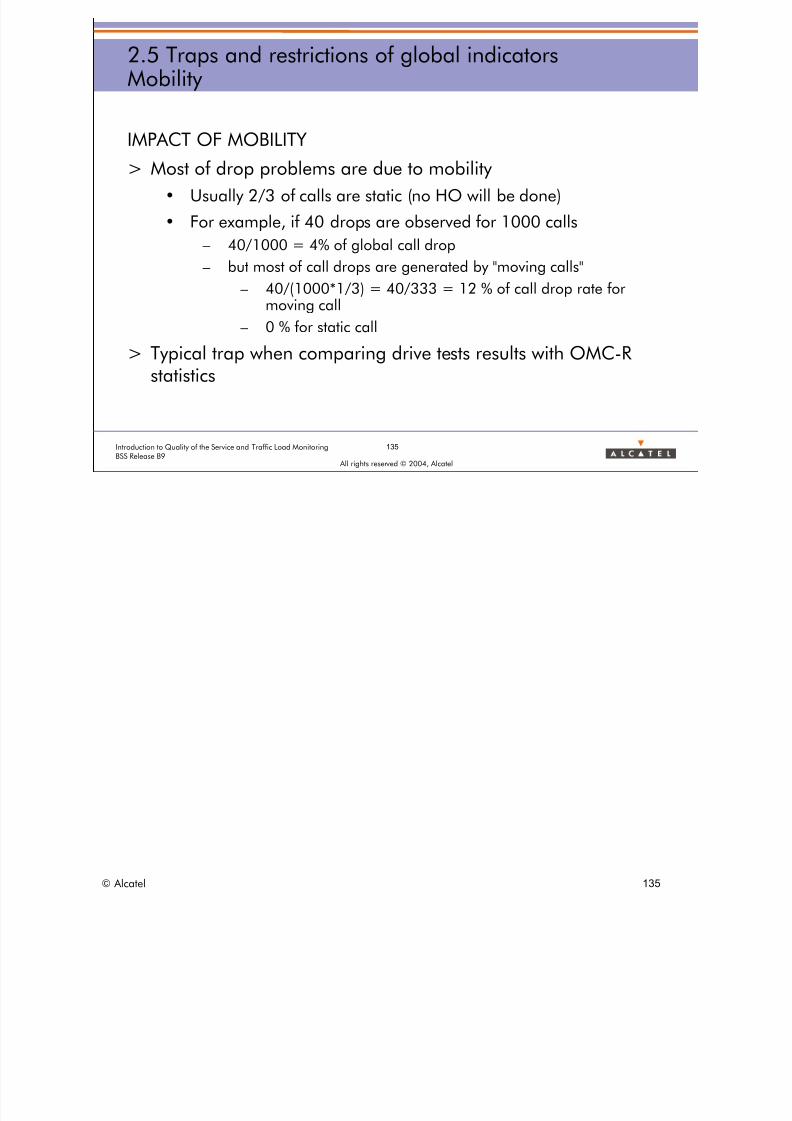
8/12/2019 QOS_B9 (Call Setup)
http://slidepdf.com/reader/full/qosb9-call-setup 135/388
135Introduction to Quality of the Service and Traffic Load MonitoringBSS Release B9
All rights reserved © 2004, Alcatel
2.5 Traps and restrictions of global indicatorsMobility
IMPACT OF MOBILITY
> Most of drop problems are due to mobility
• Usually 2/3 of calls are static (no HO will be done)
• For example, if 40 drops are observed for 1000 calls
– 40/1000 = 4% of global call drop
– but most of call drops are generated by "moving calls"
– 40/(1000*1/3) = 40/333 = 12 % of call drop rate formoving call
– 0 % for static call
> Typical trap when comparing drive tests results with OMC-Rstatistics
© Alcatel 135
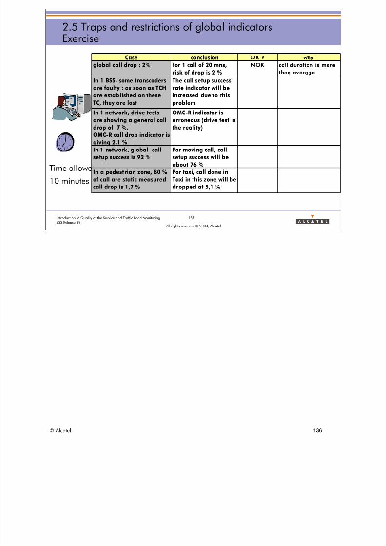
8/12/2019 QOS_B9 (Call Setup)
http://slidepdf.com/reader/full/qosb9-call-setup 136/388
:
136Introduction to Quality of the Service and Traffic Load MonitoringBSS Release B9
All rights reserved © 2004, Alcatel
2.5 Traps and restrictions of global indicatorsExercise
Time allowed
10 minutes
Case conclusion OK why
In 1 BSS, some transcodersare faulty : as soon as TCH
are established on these
TC, they are lost
The call setup successrate indicator will be
increased due to this
problem
In 1 network, drive tests
are showing a general call
drop of 7 %.
OMC-R call drop indicator is
giving 2,1 %
OMC-R indicator is
erroneous (drive test is
the reality)
In 1 network, global call
setup success is 92 %
For moving call, call
setup success will beabout 76 %
In a pedestrian zone, 80 %
of call are static measured
call drop is 1,7 %
For taxi, call done in
Taxi in this zone will be
dropped at 5,1 %
call duration is more
than average
global call drop : 2% for 1 call of 20 mns,
risk of drop is 2 %
N O K
© Alcatel 136

8/12/2019 QOS_B9 (Call Setup)
http://slidepdf.com/reader/full/qosb9-call-setup 137/388
All rights reserved © 2004, Alcatel
2 GLOBAL INDICATORS
2.6 Global indicators interpretation
© Alcatel 137

8/12/2019 QOS_B9 (Call Setup)
http://slidepdf.com/reader/full/qosb9-call-setup 138/388
Nam e value
SDCCH conge stion 1
SDCCH drop 3
TCH a ssignm e nt fa ilure ra te 2
Ca ll drop 1
Ca ll se tup succe ss ra te 96
Ca ll succe ss ra te 94
Efficie ncy of outgoing HO 92
Efficie ncy of incom ing HO 93
HO cause distribution better/ level /qual ity 70/20/1
Ne tw ork TCH a va ila bilit 98
2.6 Global indicators interpretationExercise 1
Is this network OK? Name value
SDCCH congestion %1%
SDCCH drop %3%
TCH assignment failure rate %2%
Call drop %1%
Call setup success rate %96%
Call success rate %94%
Efficiency of outgoing HO %92%Efficiency of incoming HO %93%
HO cause distribution better/level/quality 070/20/10
yNetwork TCH availability %98%
Time allowed:
5 minutes
Introduction to Quality of the Service and Traffic Load Monitoring 138
BSS Release B9 All rights reserved © 2004, Alcatel
© Alcatel 138
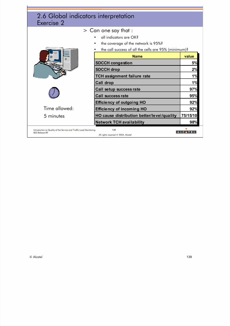
8/12/2019 QOS_B9 (Call Setup)
http://slidepdf.com/reader/full/qosb9-call-setup 139/388
Nam e value
SDCCH conge stion 5
SDCCH drop 2
TCH a ssignm e nt fa ilure ra te 1
Ca ll drop 1
Ca ll se tup succe ss ra te 97
Ca ll succe ss ra te 95
Efficie ncy of outgoing HO 92
Efficie ncy of incom ing HO 92
HO cause distribution better/ level /qual i ty 75/15/1
Ne tw ork TCH a va ila bilit 98
139Introduction to Quality of the Service and Traffic Load MonitoringBSS Release B9
All rights reserved © 2004, Alcatel
2.6 Global indicators interpretationExercise 2
> Can one say that :• all indicators are OK?
• the coverage of the network is 95%?
• the call success of all the cells are 95% (minimum)?
Time allowed:
5 minutes
%
%
%
%
%
%
%
%
0
y %
Name value
SDCCH congestion 5%
SDCCH drop 2%
TCH assignment failure rate 1%
Call drop 1%
Call setup success rate 97%
Call success rate 95%
Efficiency of outgoing HO 92%
Efficiency of incoming HO 92%
HO cause distribution better/level/quality 75/15/10
Network TCH availability 98%
© Alcatel 139

8/12/2019 QOS_B9 (Call Setup)
http://slidepdf.com/reader/full/qosb9-call-setup 140/388
Nam e value
SDCCH congestion
SDCCH drop
TCH a ssignm en t failure rate
Ca ll drop 4.6
Ca ll se tup succe ss ra te 92
Call success rate
Efficiency of outgoin g HO
Efficiency of incoming HO
HO ca use distribution be tter/le vel/qua lity
Network TCH ava ilabil it
140Introduction to Quality of the Service and Traffic Load MonitoringBSS Release B9
All rights reserved © 2004, Alcatel
2.6 Global indicators interpretationExercise 3
> Results of field tests on a network– Is the network better if QSCDR = 2%?
Time allowed:
5 minutes
%
%
y
Name value
SDCCH congestion
SDCCH drop
TCH assignment failure rate
Call drop 4.6%
Call setup success rate 92%
Call success rate
Efficiency of outgoing HO
Efficiency of incoming HO
HO cause distribution better/level/quality
Network TCH availability
© Alcatel 140

8/12/2019 QOS_B9 (Call Setup)
http://slidepdf.com/reader/full/qosb9-call-setup 141/388
All rights reserved © 2004, Alcatel
3. DETAILED INDICATORS
© Alcatel 141
8/12/2019 QOS_B9 (Call Setup)
http://slidepdf.com/reader/full/qosb9-call-setup 142/388

8/12/2019 QOS_B9 (Call Setup)
http://slidepdf.com/reader/full/qosb9-call-setup 143/388
All rights reserved © 2004, Alcatel
3. DETAILED INDICATORS
3.1 Indicator reference name
© Alcatel 143

8/12/2019 QOS_B9 (Call Setup)
http://slidepdf.com/reader/full/qosb9-call-setup 144/388
144ntroduction to Quality of the Service and Traffic Load Mon ingBSS Release B9
All rights reserved © 2004, Alcatel
itor
3.1 Indicator reference nameDescription
> Each QOS indicator has a unique REFERENCE NAME of 10
charactersUnitFamily
Procedure Type Joker
Prefix Sub-type
mandatory
optional
© Alcatel 144

8/12/2019 QOS_B9 (Call Setup)
http://slidepdf.com/reader/full/qosb9-call-setup 145/388
All rights reserved © 2004, Alcatel
3. DETAILED INDICATORS
3.2 Indicators classification
© Alcatel 145

8/12/2019 QOS_B9 (Call Setup)
http://slidepdf.com/reader/full/qosb9-call-setup 146/388
146Introduction to Quality of the Service and Traffic Load MonitoringBSS Release B9
All rights reserved © 2004, Alcatel
3.2 Indicators classificationMain categories
Classification in BSS - DEFINITION OF QUALITY OF SERVICEINDICATORS document
Control Channels
SCCP
TCH
SDCCH
Traffic load
Call statistics
RTCH
SDCCH
Global QoS
Couple of cells
SDCCH /TCHHO repartition
Intracell HO
Incoming HO
Outgoing HO
HO causes
Handover
statistics
Resource
availability
Multiband
Multilayer / MultibandNetwork
Concentric cells
Directed retry
Densification
techniques
GSM
indicators
© Alcatel 146
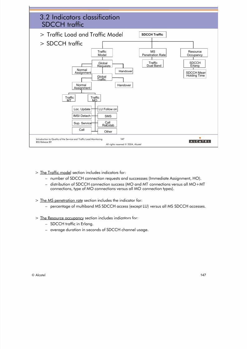
8/12/2019 QOS_B9 (Call Setup)
http://slidepdf.com/reader/full/qosb9-call-setup 147/388
st b
147Introduction to Quality of the Service and Traffic Load MonitoringBSS Release B9
All rights reserved © 2004, Alcatel
3.2 Indicators classificationSDCCH traffic
> Traffic Load and Traffic Model
> SDCCH traffic
SDCCH Traffic
Traffic
MT
Traffic
MO
Loc. Update
IMSI Detach
Sup. Service
Call
LU Follow on
SMS
CallRe-Estab
Other
MSPenetration Rate
TrafficDual Band
ResourceOccupancy
SDCCHErlang
SDCCH MeanHolding TimeGlobal
Traffic
GlobalRequests
TrafficModel
HandoverNormal Assignment
Normal Assignment
Handover
> The Traffic model section includes indicators for:
– number of SDCCH connection requests and successses (Immediate Assignment, HO).
– distribution of SDCCH connection success (MO and MT connections versus all MO+MTconnections, type of MO connections versus all MO connection types).
> The MS penetration rate section includes the indicator for:– percentage of multiband MS SDCCH access (except LU) versus all MS SDCCH accesses.
> The Resource occupancy section includes indicators for:
– SDCCH traffic in Erlang.
– average duration in seconds of SDCCH channel usage.
© Alcatel 147

8/12/2019 QOS_B9 (Call Setup)
http://slidepdf.com/reader/full/qosb9-call-setup 148/388
148Introduction to Quality of the Service and Traffic Load MonitoringBSS Release B9
All rights reserved © 2004, Alcatel
3.2 Indicators classificationTCH traffic
> Traffic Load and Traffic Model
> TCH trafficRTCH Traffic
Resource
Occupancy
TCHErlang
Full Rate
Erlang
Full Rate Allocated
Full RateMean TCH
Time
Half Rate
Erlang
Half Rate Allocated
Half RateMean TCH
Time
Blocking Peak
Ratio ofHR Traffic
TCHMultiband
Occupancy
Traffic Model
REQUESTS
Assign / HO / DR
SUCCESS Assign/ HO/ DR
HO PER CALL
REQUESTS
FR, DR, DR/EFR, AMR, DATA
Speech Version&
Channel Type
ALLOCATIONSFR, HR, EFR, AMR, DATA
SUCCESS AMR / TFO
> The Speech Version and Channel Type section includes indicators for:
– distribution of TCH allocation requests (FR/DR/DR+EFR/AMR/DATA).
– distribution of TCH allocation successes (FR/DR/DR+EFR/AMR/DATA).
– rate of TCH AMR allocation successes.
– rate of TFO calls versus all speech calls.
> The Traffic model section includes indicators for:
– number of TCH connection requests and successes (Normal Assignment, HO, DR).
– rate of TCH allocation successes for HO+DR versus all TCH allocations (NA+HO+DR).
– number of HOs per call.
> The Resource occupancy section includes indicators for:
– RTCH traffic in Erlang (FR+HR, FR, HR, multiband).
– average duration in seconds of RTCH channel usage (FR+HR, FR, HR).
– number of TCH FR allocations and number of TCH HR allocations.
– rate of TCH HR allocations versus all TCH allocations (FR+HR).
– TCH peak of blocking (TCH congestion time).
© Alcatel 148

8/12/2019 QOS_B9 (Call Setup)
http://slidepdf.com/reader/full/qosb9-call-setup 149/388
3.2 Indicators classificationSCCP resource occupancy / Control channels traffic
> Traffic Load and Traffic Model > SCCP resource occupancy
• SCCP traffic in Erlang
> Traffic Load and Traffic Model > Control Channels traffic
• PCH channel load
• AGCH channel load
• RACH channel load
149Introduction to Quality of the Service and Traffic Load MonitoringBSS Release B9
All rights reserved © 2004, Alcatel
© Alcatel 149

8/12/2019 QOS_B9 (Call Setup)
http://slidepdf.com/reader/full/qosb9-call-setup 150/388
150Introduction to Quality of the Service and Traffic Load MonitoringBSS Release B9
All rights reserved © 2004, Alcatel
3.2 Indicators classificationQoS SDCCH
> GLOBAL Quality of Service
> SDCCHSDCCH
Established
Phase
Drop Rate
Drop Radio Drop HO
Unsuccess
Congestion
Assignment Phase
/
Handover
RadioFailure
BSS Failure
Access Reject
Dynamic Allocation
Drop BSS
>The Assignment phase section includes indicators for the Radio Link Establishment procedure:•global SDCCH access failure rate.•specific SDCCH access failure rate per type of problem (SDCCH congestion, radio, BSS).•specific indicators for Dynamic SDCCH Allocation:
Stored Indicators (see Dynamic SDCCH Allocation in the Global Indicators section)DYTROFN.= MC800DYAHCATAN = MC801aDYAHCATMN = MC801bDYAHCASAN. = MC802aDYAHCASMN.= MC802bDYN = number of Dynamic timeslots (given by configuration file) = Cell_NB_DYNComputed indicators
DYAHCATAR: average rate of busy TCH (FR of HR) allocated on dynamic SDCCH/8 timeslotsFormula: tdiv* (DYAHCATAN,DYTROFN,0,0)DYAHCATMR: maximum rate of busy TCH (FR of HR) allocated on dynamic SDCCH/8 timeslotsFormula: tdiv (DYAHCATMN,DYTROFN,0,0)DYAHCASAR: average rate of busy SDCCH sub-channels allocated on the dynamic SDCCH/8timeslotsFormula: tdiv (DYAHCASAN,DYTROFN,0,0)Impact on existing Indicators: Apart of modification due to introduction of Dynamic SDCCH/8 timeslot, the general formula of these indicators are redesigned, to be simpler. TCRRDN, TCRROFN, TCAHCGUN, TCAVAR (removed as it is the same as TCTRAR), TCTRAVE, TCTRAR, TCTRTCE, SDAHCGUN, SDAVAR, SDRRDN, SDRROFN, SDTRAVE
>The Handover procedure section includes the indicator for the preparation of the SDCCH HO procedure:•rate of SDCCH HO failure due to SDCCH congestion >The Established phase section includes indicators for SDCCH Phase:
•global SDCCH drop rate.•specific SDCCH drop rate per type of problem (radio, HO, BSS).
* tdiv(A,B,0,0) means that it is equal to A/B if B ≠0 or to 0 if B = 0
© Alcatel 150

8/12/2019 QOS_B9 (Call Setup)
http://slidepdf.com/reader/full/qosb9-call-setup 151/388
151Introduction to Quality of the Service and Traffic Load MonitoringBSS Release B9
All rights reserved © 2004, Alcatel
3.2 Indicators classificationQoS RTCH
> GLOBAL Quality of service
> RTCH
DirectedRetry
RTCH
Unsuccess
Assignment Phase/
Handover
Global RadioCongestion Level
Congestion
RadioFailure
BSSFailure
EstablishedPhase
Drop rate
Drop Radio
Drop BSS
Drop HO
Preemption
PreemptionPhase
PCI =1 PVI =1
Requests
Allocation
with / withoutPreemption
Failure
Success
Success
QueuingPhase
Queue Length
AssignQueuing Fail
AssignQueued
& Reject
Queued
Success
Queue Full
Higher Priority
Timeout
AssignQueued
Normal Assign.
>The Assignment phase section includes indicators for the TCH Normal Assignment procedure:•global RTCH assignment failure rate (called unsuccess rate).•specific RTCH assignment failure rate per type of problem (RTCH congestion, radio, BSS).•global radio congestion level (number of cells congested in the network).
>The Handover procedure section includes indicators for the global HO procedure(intracell+intercell internal + intercell external):
•rate of RTCH incoming HO failure due to RTCH congestion.•specific RTCH outgoing HO failure rate per type of problem (congestion, radio - ReversionOld Channel, radio drop, BSS).
© Alcatel 151

8/12/2019 QOS_B9 (Call Setup)
http://slidepdf.com/reader/full/qosb9-call-setup 152/388
152Introduction to Quality of the Service and Traffic Load MonitoringBSS Release B9
All rights reserved © 2004, Alcatel
3.2 Indicators classificationQoS call statistics
> GLOBAL Quality of service
> Call statistics Call Statistics
Call Success
Call SetupSuccess Rate
CallSuccess Rate
Cell QualityFactor Absolute
Cell QualityFactor Relative
Call Drop
Call Drop Rate
Drop Radio Drop BSSDrop HO
Transcoder Failure
BSS Internal Failure
Call DropEnd User Rate
Preemption
>The Call Drop section includes indicators for the TCH Phase:•global call drop rate.•specific call drop rate per type of problem (radio, HO, BSS int., TransCoder, preemption).
>The Call Success section includes indicators for the global call procedure (speech):•rate of call setup success.•rate of call success.•global cell quality factor.
© Alcatel 152

8/12/2019 QOS_B9 (Call Setup)
http://slidepdf.com/reader/full/qosb9-call-setup 153/388
3.2 Indicators classificationHandover causes
> Handover STATISTICS
> Handover causes
– Fast traffic HO taken into account type of counter for dual band HO
Handover causes
HO causes
All
HO
cause
distribution
Outgoing HO Incoming HO
HO standard
cause
distribution
HO cause
category
distribution
HO causes per Adjacency
HO cause
category
distribution
153Introduction to Quality of the Service and Traffic Load MonitoringBSS Release B9
All rights reserved © 2004, Alcatel
>The Handover causes section includes indicators of HO causes distribution corresponding to outgoing handovers relating to a cell:•distribution of HO causes taking into account all possible HO causes (quality UL, level DL, distance, power budget,concentric cell cause, micro cell cause, traffic, etc.).•distribution of HO standard causes taking into account only HO standard causes (quality UL, quality DL, level UL, levelDL, interference UL, interference DL, distance, power budget).
>The Handover causes per adjacency section includes indicators of HO causes distribution corresponding to outgoing and incominghandovers relating to a couple of serving/target cells:
•distribution of HO cause categories taking into account 3 categories (emergency [quality, level, interference, distance,power budget]), better condition [power budget, capture], traffic, forced directed retry).
C449 (type 6) in type 110 (as MC449) improves the result of all HO cause Indicators: (B8 Introduction) C449 = MC449 = number of handover attempts with cause 28 (Fast traffic handover) The Indicator TOTALHO (HCN) is impacted as well as the following indicators:
HCSTBPBR, HCCCR, HCSTEDIR, HCSTEDMR, HCSTIFDR, HCSTLVDR, HCSTQLDR, HCSTEIFR, HCSTELVR, HCMCR, HCSTEQLR, HCSTIFUR, HCSTLVUR, HCSTQLUR, HCNTBDR, HCSTBTFR, HCSTAMR, HCSTAMFR, HCSTAMHR, HCSTBTRFR type 32 of counter (Change of frequency band measurements) (B8 Introduction) Type 32 is defined as Standard and provides information to observe handovers between different frequency bands. C403a = NB_INC_EXT_TCH_HO_NEW_BAND_ATPT = Number of incoming external TCH (in HR or FR usage) handover attempts including a change of the (TCH) frequency band. C403b = NB_INC_EXT_TCH_HO_NEW_BAND_SUCC = Number of incoming external TCH (in HR or FR usage) handover successes including a change of the (TCH) frequency band. C404a = NB_OUT_EXT_TCH_HO_NEW_BAND_ATPT = Number of outgoing external TCH (in HR or FR usage) handover attempts including a change of the (TCH) frequency band. C404b = NB_OUT_EXT_TCH_HO_NEW_BAND_SUCC = Number of outgoing external TCH (in HR or FR usage) handover successes including a change of the (TCH) frequency band. C420a = NB_INC_INT_TCH_HO_NEW_BAND_ATPT = Number of incoming internal TCH (in HR or FR usage) handover attempts including a change of the (TCH) frequency band.
C420b = NB_INC_INT_TCH_HO_NEW_BAND_SUCC = Number of incoming internal TCH (in HR or FR usage) handover successes including a change of the (TCH) frequency band. C421a NB_OUT_INT_TCH_HO_NEW_BAND_ATPT = Number of outgoing internal TCH (in HR or FR usage) handover attempts including a change of the (TCH) frequency band. C421b NB_OUT_INT_TCH_HO_NEW_BAND_SUCC = Number of outgoing internal TCH (in HR or FR usage) handover successes including a change of the (TCH) frequency band.
© Alcatel 153

8/12/2019 QOS_B9 (Call Setup)
http://slidepdf.com/reader/full/qosb9-call-setup 154/388
154Introduction to Quality of the Service and Traffic Load MonitoringBSS Release B9
All rights reserved © 2004, Alcatel
3.2 Indicators classificationOutgoing handovers
> Handover STATISTICS
> Outgoing handovers
– LAPD counter to analyze the cause of delay in HO procedures
Failure With Reversion
Call Drop Rate
Efficiency
Preparation Success Rate
Intra-BSC
Failure With Reversion
Call Drop Rate
Efficiency
Preparation Success Rate
External
Call Drop Rate
Efficiency
Success Rate
Intra-BSC & External
Outgoing HO
(See comments)
>The Outgoing Intra BSC intercell section includes indicators corresponding to the efficiency of outgoing intercellinternal handovers relating to a cell (serving):
•efficiency ot the preparation phase (target TCH allocation) of the outgoing handovers performed from onecell to any of its neighboring cells belonging to the same BSS.•efficiency ot the execution phase (old to new TCH channel change) of the outgoing handovers performedfrom one cell to any of its neighboring cells belonging to the same BSS.•distribution of outgoing intra BSC intercell HO failures per type of problem (radio drop, radio - ReversionOld Channel, BSS).
>The Outgoing Inter BSC intercell section includes indicators corresponding to the efficiency of outgoing intercellexternal handovers relating to a cell (serving):
•efficiency ot the preparation phase (target TCH allocation) of the outgoing handovers performed from onecell to any of its neighboring cells not belonging to the same BSS.•efficiency ot the execution phase (old to new TCH channel change) of the outgoing handovers performedfrom one cell to any of its neighboring cells not belonging to the same BSS.•distribution of outgoing inter BSC intercell HO failures per type of problem (radio drop, radio - ReversionOld Channel, BSS).
>The Outgoing Intra BSC + Inter BSC intercell section includes indicators corresponding to the efficiency of alloutgoing intercell handovers relating to a cell (serving):
•global efficiency ot the outgoing handovers performed from one cell to any of its neighboring cells whether they belong to the same BSS or not •efficiency ot the execution phase (old to new TCH channel change) of the outgoing handovers performed from one cell to any of its neighboring cells whether they belong to the same BSS or not. •outgoing intra BSC + inter BSC intercell HO drop rate per type of problem (radio drop, radio - Reversion Old Channel, BSS).
>When the BSC is congested on the downlink, some messages are discarded. This may result for example in call establishment failures, loss of paging messages or delay in handover procedures. A LapD counter that indicates the time an LapD link is congested is created to analyze the cause of a degraded QoS. This counter is implemented in type 7 and thus is only available in a detailed measurement campaign.
Counter: L1.18: TIME_LAPD_CONG Definition: Time in seconds during which the LapD link is congested in transmission in the BSC.
© Alcatel 154
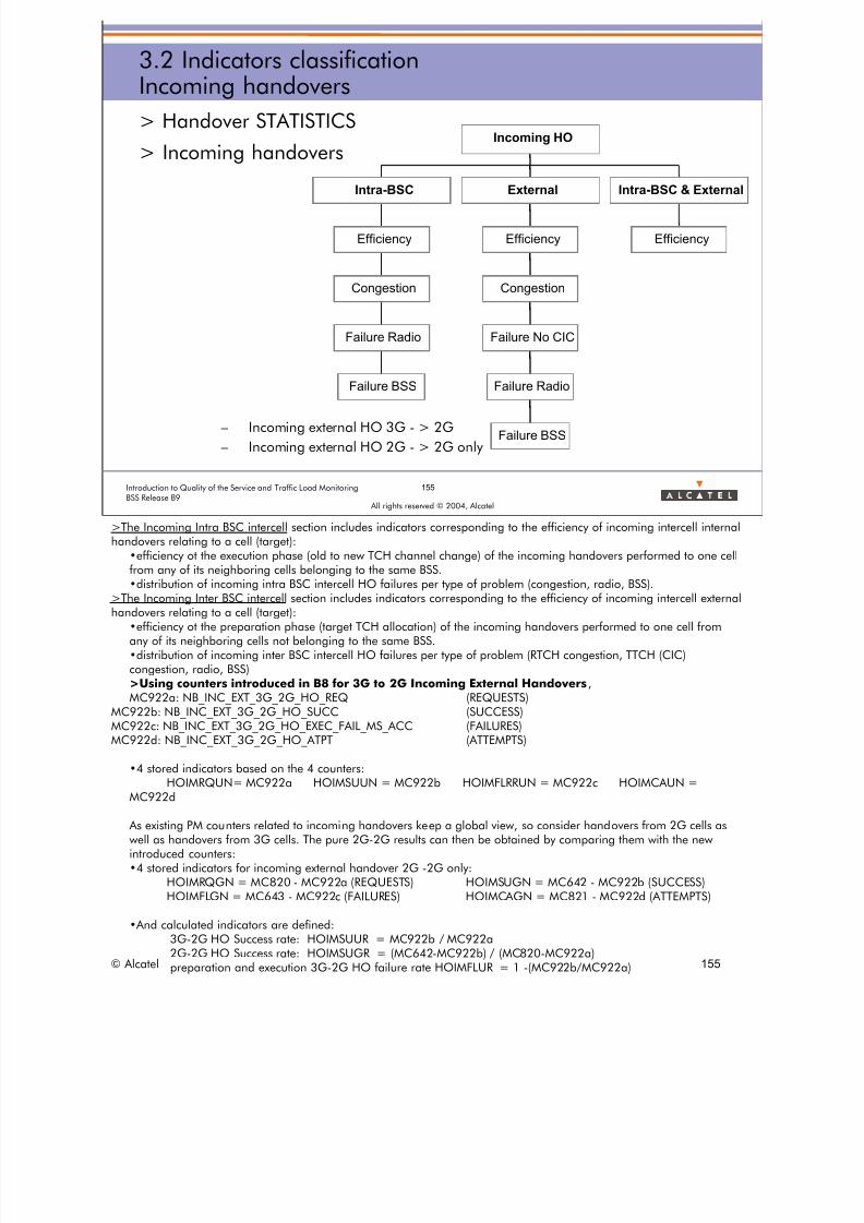
8/12/2019 QOS_B9 (Call Setup)
http://slidepdf.com/reader/full/qosb9-call-setup 155/388
155Introduction to Quality of the Service and Traffic Load MonitoringBSS Release B9
All rights reserved © 2004, Alcatel
3.2 Indicators classificationIncoming handovers
> Handover STATISTICS
> Incoming handovers
– Incoming external HO 3G - > 2G
– Incoming external HO 2G - > 2G only
Failure BSS
Failure Radio
Congestion
Efficiency
Intra-BSC
Failure BSS
Failure Radio
Failure No CIC
Congestion
Efficiency
External
Efficiency
Intra-BSC & External
Incoming HO
>The Incoming Intra BSC intercell section includes indicators corresponding to the efficiency of incoming intercell internalhandovers relating to a cell (target):
•efficiency ot the execution phase (old to new TCH channel change) of the incoming handovers performed to one cellfrom any of its neighboring cells belonging to the same BSS.•distribution of incoming intra BSC intercell HO failures per type of problem (congestion, radio, BSS).
>The Incoming Inter BSC intercell section includes indicators corresponding to the efficiency of incoming intercell externalhandovers relating to a cell (target):
•efficiency ot the preparation phase (target TCH allocation) of the incoming handovers performed to one cell from any of its neighboring cells not belonging to the same BSS. •distribution of incoming inter BSC intercell HO failures per type of problem (RTCH congestion, TTCH (CIC) congestion, radio, BSS) >Using counters introduced in B8 for 3G to 2G Incoming External Handovers, MC922a: NB_INC_EXT_3G_2G_HO_REQMC922b: NB_INC_EXT_3G_2G_HO_SUCC
MC922c: NB_INC_EXT_3G_2G_HO_EXEC_FAIL_MS_ACCMC922d: NB_INC_EXT_3G_2G_HO_ATPT
(REQUESTS)(SUCCESS)(FAILURES)(ATTEMPTS)
•4 stored indicators based on the 4 counters:HOIMRQUN= MC922a HOIMSUUN = MC922b
MC922dHOIMFLRRUN = MC922c HOIMCAUN =
As existing PM counters related to incoming handovers keep a global view, so consider handovers from 2G cells aswell as handovers from 3G cells. The pure 2G-2G results can then be obtained by comparing them with the newintroduced counters:•4 stored indicators for incoming external handover 2G -2G only:
HOIMRQGN = MC820 - MC922a (REQUESTS) HOIMSUGN = MC642 - MC922b (SUCCESS)HOIMFLGN = MC643 - MC922c (FAILURES) HOIMCAGN = MC821 - MC922d (ATTEMPTS)
•And calculated indicators are defined:3G-2G HO Success rate: HOIMSUUR = MC922b / MC922a2G-2G HO Success rate: HOIMSUGR = (MC642-MC922b) / (MC820-MC922a)
© Alcatel preparation and execution 3G-2G HO failure rate HOIMFLUR = 1 -(MC922b/MC922a) 155
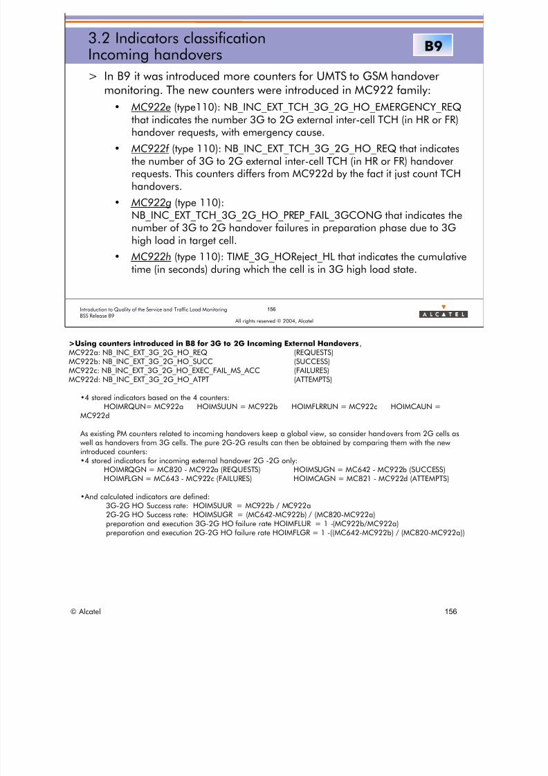
8/12/2019 QOS_B9 (Call Setup)
http://slidepdf.com/reader/full/qosb9-call-setup 156/388
156Introduction to Quality of the Service and Traffic Load MonitoringBSS Release B9
All rights reserved © 2004, Alcatel
3.2 Indicators classificationIncoming handovers
> In B9 it was introduced more counters for UMTS to GSM handovermonitoring. The new counters were introduced in MC922 family:
• MC922e (type110): NB_INC_EXT_TCH_3G_2G_HO_EMERGENCY_REQthat indicates the number 3G to 2G external inter-cell TCH (in HR or FR)handover requests, with emergency cause.
• MC922f (type 110): NB_INC_EXT_TCH_3G_2G_HO_REQ that indicatesthe number of 3G to 2G external inter-cell TCH (in HR or FR) handoverrequests. This counters differs from MC922d by the fact it just count TCHhandovers.
• MC922g (type 110):NB_INC_EXT_TCH_3G_2G_HO_PREP_FAIL_3GCONG that indicates thenumber of 3G to 2G handover failures in preparation phase due to 3Ghigh load in target cell.
• MC922h (type 110): TIME_3G_HOReject_HL that indicates the cumulativetime (in seconds) during which the cell is in 3G high load state.
B9
>Using counters introduced in B8 for 3G to 2G Incoming External Handovers,MC922a: NB_INC_EXT_3G_2G_HO_REQMC922b: NB_INC_EXT_3G_2G_HO_SUCCMC922c: NB_INC_EXT_3G_2G_HO_EXEC_FAIL_MS_ACCMC922d: NB_INC_EXT_3G_2G_HO_ATPT
(REQUESTS)(SUCCESS)(FAILURES)(ATTEMPTS)
•4 stored indicators based on the 4 counters:HOIMRQUN= MC922a HOIMSUUN = MC922b
MC922dHOIMFLRRUN = MC922c HOIMCAUN =
As existing PM counters related to incoming handovers keep a global view, so consider handovers from 2G cells as
well as handovers from 3G cells. The pure 2G-2G results can then be obtained by comparing them with the newintroduced counters:•4 stored indicators for incoming external handover 2G -2G only:
HOIMRQGN = MC820 - MC922a (REQUESTS) HOIMSUGN = MC642 - MC922b (SUCCESS)HOIMFLGN = MC643 - MC922c (FAILURES) HOIMCAGN = MC821 - MC922d (ATTEMPTS)
•And calculated indicators are defined:3G-2G HO Success rate: HOIMSUUR = MC922b / MC922a2G-2G HO Success rate: HOIMSUGR = (MC642-MC922b) / (MC820-MC922a)preparation and execution 3G-2G HO failure rate HOIMFLUR = 1 -(MC922b/MC922a)preparation and execution 2G-2G HO failure rate HOIMFLGR = 1 -((MC642-MC922b) / (MC820-MC922a))
© Alcatel 156

8/12/2019 QOS_B9 (Call Setup)
http://slidepdf.com/reader/full/qosb9-call-setup 157/388
© Alcatel 157
>The Intracell section includes indicators corresponding to the efficiency of intracell handoversperformed within a cell:
•efficiency ot the execution phase (old to new TCH channel change) of the intracellhandovers performed within a cell.•distribution of intracell HO failures per type of problem (congestion, radio drop, radio -Reversion Old Channel, BSS).
157Introduction to Quality of the Service and Traffic Load MonitoringBSS Release B9
All rights reserved © 2004, Alcatel
3.2 Indicators classificationIntra-cell handovers
> Handover STATISTICS
> Intracell handovers
> New B9 counters: HO Cause 30
• NB_TCH_HO_REQ_30_ReturnCSZone
=MC480 (Type 110)
• NB_TCH_HO_ATPT_30_ReturnCSZone=MC481 (Type 110)
CDR Radio CDR BSS
Failure With Reversion
Failure BSS
Call Drop Rate
Congestion
Efficiency
Intracell HO
B9
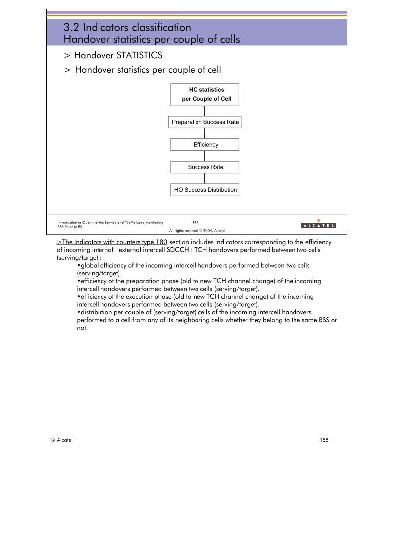
8/12/2019 QOS_B9 (Call Setup)
http://slidepdf.com/reader/full/qosb9-call-setup 158/388
© Alcatel 158
158Introduction to Quality of the Service and Traffic Load MonitoringBSS Release B9
All rights reserved © 2004, Alcatel
3.2 Indicators classificationHandover statistics per couple of cells
> Handover STATISTICS
> Handover statistics per couple of cell
HO Success Distribution
Success Rate
Efficiency
Preparation Success Rate
HO statistics
per Couple of Cell
>The Indicators with counters type 180 section includes indicators corresponding to the efficiencyof incoming internal+external intercell SDCCH+TCH handovers performed between two cells(serving/target):
•global efficiency of the incoming intercell handovers performed between two cells(serving/target).•efficiency ot the preparation phase (old to new TCH channel change) of the incomingintercell handovers performed between two cells (serving/target).•efficiency ot the execution phase (old to new TCH channel change) of the incomingintercell handovers performed between two cells (serving/target).•distribution per couple of (serving/target) cells of the incoming intercell handovers
performed to a cell from any of its neighboring cells whether they belong to the same BSS ornot.

8/12/2019 QOS_B9 (Call Setup)
http://slidepdf.com/reader/full/qosb9-call-setup 159/388
All rights reserved © 2004, Alcatel
4 HANDOVER INDICATORS
© Alcatel 159
8/12/2019 QOS_B9 (Call Setup)
http://slidepdf.com/reader/full/qosb9-call-setup 160/388
160Introduction to Quality of the Service and Traffic Load MonitoringBSS Release B9
All rights reserved © 2004, Alcatel
4 Handover indicatorsSession presentation
> Objective: to be able to explain what are the main Handover
counters and indicators provided by the Alcatel BSS in order tomonitor the quality of handovers
> Program:
• 4.1 Intra-cell handover indicators per cell
• 4.2 Internal handover indicators per cell
• 4.3 External handover indicators per cell• 4.4 Handover indicators per couple of cells
© Alcatel 160

8/12/2019 QOS_B9 (Call Setup)
http://slidepdf.com/reader/full/qosb9-call-setup 161/388
All rights reserved © 2004, Alcatel
4 HANDOVER INDICATORS
4.1 Intra-cell handover indicatorsper cell
© Alcatel 161

8/12/2019 QOS_B9 (Call Setup)
http://slidepdf.com/reader/full/qosb9-call-setup 162/388
162Introduction to Quality of the Service and Traffic Load MonitoringBSS Release B9
All rights reserved © 2004, Alcatel
4.1 Intra-cell handover indicators per cellHandover types
HO FAIL. CASES > HO Reminder
> Intra-Cell: Handover between twoTCHs of the same cell
> Internal
• between two cells of the sameBSC
• also called intra BSC
• and not using the forced externalhandover mode
> External
• between two cells of differentBSCs
• also called inter BSC
• or between two cells of the sameBSC when using the forcedexternal handover mode
TCH/(SDCCH) Handover
> Synchronous
• between 2 cells• sharing the same clocks
• collocated
• usually 2 sectors of the same BTS
– tunable at OMC-R level
> Asynchronous
• not synchronous for any reason
• no dedicated monitoring for
synchronous/asynchronous HO> Incoming
• as considering the target cell
> Outgoing
• as considering the serving cell
© Alcatel 162
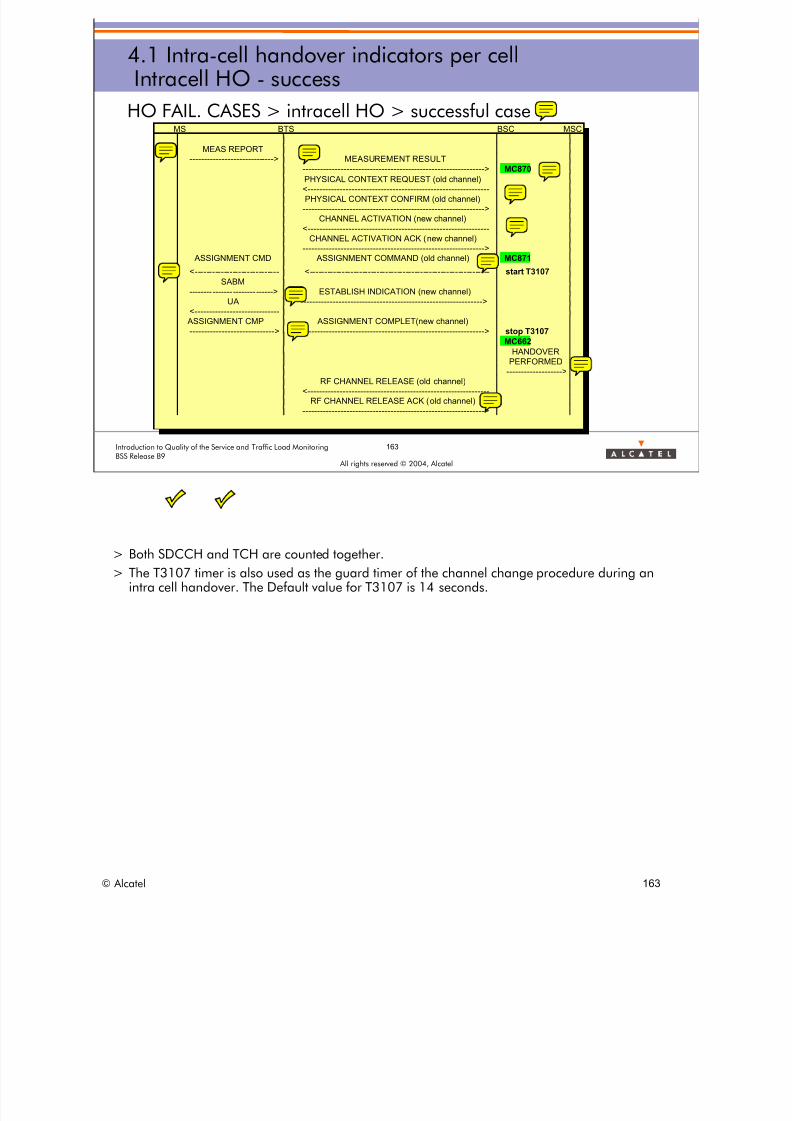
8/12/2019 QOS_B9 (Call Setup)
http://slidepdf.com/reader/full/qosb9-call-setup 163/388
163Introduction to Quality of the Service and Traffic Load MonitoringBSS Release B9
All rights reserved © 2004, Alcatel
4.1 Intra-cell handover indicators per cellIntracell HO - success
HO FAIL. CASES > intracell HO > successful caseMS BTS BSC MSC
MEAS REPORT
-----------------------------> MEASUREMENT RESULT--------------------------------------------------------------> MC870
PHYSICAL CONTEXT REQUEST (old channel)
<-------------------------------------------------------------
PHYSICAL CONTEXT CONFIRM (old channel)-------------------------------------------------------------->
CHANNEL ACTIVATION (new channel)
<-------------------------------------------------------------
CHANNEL ACTIVATION ACK (new channel)
--------------------------------------------------------------> ASSIGNMENT CMD ASSIGNMENT COMMAND (old channel) MC871
<---------------------------- <------------------------------------------------------------- start T3107
SABM
-------- ------- -------- ------> ESTABLISH INDICATION (new channel)
UA -------------------------------------------------------------->
<----------------------------
ASSIGNMENT CMP ASSIGNMENT COMPLET(new channel)-----------------------------> --------------------------------------------------------------> stop T3107
MC662
HANDOVER
PERFORMED
------------------->
RF CHANNEL RELEASE (old channel)
<-------------------------------------------------------------RF CHANNEL RELEASE ACK (old channel)
-------------------------------------------------------------->
> Both SDCCH and TCH are counted together.
> The T3107 timer is also used as the guard timer of the channel change procedure during anintra cell handover. The Default value for T3107 is 14 seconds.
© Alcatel 163

8/12/2019 QOS_B9 (Call Setup)
http://slidepdf.com/reader/full/qosb9-call-setup 164/388
4.1 Intra-cell handover indicators per cellIntracell HO - failures
HO FAIL. CASES > intracell HO Failures
> Handover Preparation:
• congestion
• BSS problem (no specific counter)
> Handover Execution:
• reversion to old channel
• drop radio
• BSS problem (no specific counter)
164Introduction to Quality of the Service and Traffic Load MonitoringBSS Release B9
All rights reserved © 2004, Alcatel
© Alcatel 164
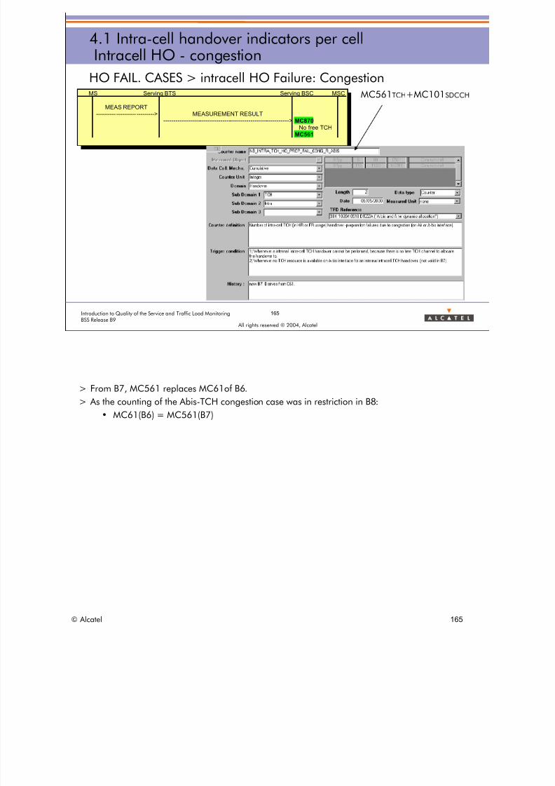
8/12/2019 QOS_B9 (Call Setup)
http://slidepdf.com/reader/full/qosb9-call-setup 165/388
165Introduction to Quality of the Service and Traffic Load MonitoringBSS Release B9
All rights reserved © 2004, Alcatel
4.1 Intra-cell handover indicators per cellIntracell HO - congestion
HO FAIL. CASES > intracell HO Failure: CongestionMC561TCH+MC101SDCCHMS Serving BTS Serving BSC MSC
MEAS REPORT
---------- ---------- ---------> MEASUREMENT RESULT-------------------------------------------------------------->MC870
No free TCHMC561
> From B7, MC561 replaces MC61of B6. > As the counting of the Abis-TCH congestion case was in restriction in B8:
• MC61(B6) = MC561(B7)
© Alcatel 165

8/12/2019 QOS_B9 (Call Setup)
http://slidepdf.com/reader/full/qosb9-call-setup 166/388
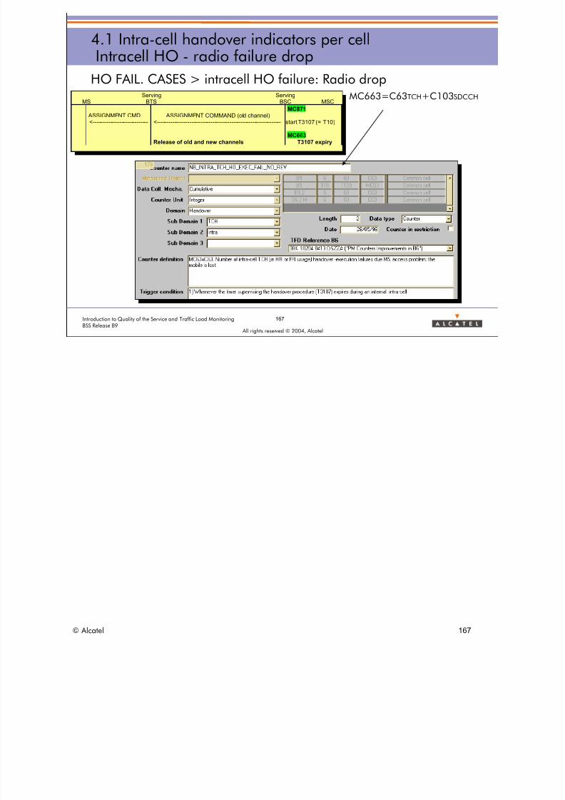
8/12/2019 QOS_B9 (Call Setup)
http://slidepdf.com/reader/full/qosb9-call-setup 167/388
167Introduction to Quality of the Service and Traffic Load MonitoringBSS Release B9
All rights reserved © 2004, Alcatel
4.1 Intra-cell handover indicators per cellIntracell HO - radio failure drop
HO FAIL. CASES > intracell HO failure: Radio dropMC663=C63TCH+C103SDCCHServing Serving
MS BTS BSC MSC
MC871
ASSIGNMENT CMD ASSIGNMENT COMMAND (old channel)<---------------------------- <---------------------------------------------------------------- start T3107 (= T10)
MC663Release of old and new channels T3107 expiry
© Alcatel 167

8/12/2019 QOS_B9 (Call Setup)
http://slidepdf.com/reader/full/qosb9-call-setup 168/388
168Introduction to Quality of the Service and Traffic Load MonitoringBSS Release B9
All rights reserved © 2004, Alcatel
4.1 Intra-cell handover indicators per cellIntracell HO - BSS problem
HO FAIL. CASES > intracell HO failure: BSS drop
> no specific counter
Serving ServingMS BTS BSC MSC
MC871 ASSIGNMENT CMD ASSIGNMENT COMMAND (old channel)<---------------------------- <---------------------------------------------------------------- start T3107 (= T10)
--------------------------------------- >
CLEAR REQUEST
O&M interventionRadio interface failure
> Intra cell HO failures due to BSS problems are deduced from other counters.
© Alcatel 168

8/12/2019 QOS_B9 (Call Setup)
http://slidepdf.com/reader/full/qosb9-call-setup 169/388
169Introduction to Quality of the Service and Traffic Load MonitoringBSS Release B9
All rights reserved © 2004, Alcatel
4.1 Intra-cell handover indicators per cellIntracell HO - counters
HO FAIL. CASES > intracell HO counters
Request MC870
Congestion MC561+MC101BSS Pb MC870-MC871-(MC561+MC101)
Attempt MC871
Reversion old channel MC667
Drop radio MC663
BSS Pb MC871-MC662-MC667-MC663
Success MC662
Preparation
Execution
INTRACELL Handover
REQUEST
CONGESTION
ATTEMPT
REVERSION OLD CHANNEL
DROP RADIO
BSS PB
SUCCESS
BSS PB
Preparation Failure
Execution Failure
© Alcatel 169

8/12/2019 QOS_B9 (Call Setup)
http://slidepdf.com/reader/full/qosb9-call-setup 170/388
All rights reserved © 2004, Alcatel
4 HANDOVER INDICATORS
4.2 Internal handover indicators per cell
© Alcatel 170

8/12/2019 QOS_B9 (Call Setup)
http://slidepdf.com/reader/full/qosb9-call-setup 171/388
171Introduction to Quality of the Service and Traffic Load MonitoringBSS Release B9
All rights reserved © 2004, Alcatel
4.2 Internal handover indicators per cellInternal HO - success
HO FAIL. CASES > internal HO > success caseThe same inter-cell
handover procedure
leads to anincrementation of twosets of counters:
incoming HO counters forthe target cell: MC830,MC831, MC652, etc.
outgoing HO counters forthe serving cell:MC655A, MC660,
MC656, etc.
In HO_PERFORMED MESSAGE
>Target cell (CI,LAC)>"cause" of HO
MS serving cell target cell BSC MSC
MEAS REP
-------------- ---------> MEASUREMENT RESULT
------------------------------------------------------------------------> MC830, MC655A
CHANNEL ACTIVATION
<---------------------------------
CHAN ACTIV ACK
---------------------------------->
HO CMD HANDOVER COMMAND
<---------------------- <----------------------------------------------------------------------- start T3103
MC831, MC660
start T3124
HANDOVER ACCESS
------------------------------------------------------------->
-------------- -------------- ---------------- -------------- ---> HO DETECTION
PHYSICAL INFORMATION --------------- --------------- ---->
<------------------------------------------------------------ start T3105
stop T3124
start T200
-------------- ---------- SABM -------------- -------------> stop T3105
<-------------------------- UA ---------------------------- ESTABLISH INDICATION
stop T200 --------------- --------------- ---->
HANDOVER COMPLETE HO CMP stop T3103
-------------- -------------- ---------------- -------------- ---> --------------- --------------- ----> HO PERFORMED
------------------------>
Release of old TCH MC652, MC656
> Both SDCCH and TCH are counted together.
© Alcatel 171

8/12/2019 QOS_B9 (Call Setup)
http://slidepdf.com/reader/full/qosb9-call-setup 172/388
172Introduction to Quality of the Service and Traffic Load MonitoringBSS Release B9
All rights reserved © 2004, Alcatel
4.2 Internal handover indicators per cellIncoming internal HO - failures
HO FAIL. CASES > Incoming internal HO failures:
> Handover procedure from the target cell point of view
> Handover Preparation:
• congestion: no RTCH available in the target cell
– does not concern the outgoing side (serving cell point of view)
• BSS problem (no specific counter)
> Handover Execution:
• radio problem: the MS fails to access the new channel
– the reversion/drop discrimination concerns only the serving cell
• BSS problem (no specific counter)
© Alcatel 172

8/12/2019 QOS_B9 (Call Setup)
http://slidepdf.com/reader/full/qosb9-call-setup 173/388
173Introduction to Quality of the Service and Traffic Load MonitoringBSS Release B9
All rights reserved © 2004, Alcatel
4.2 Internal handover indicators per cellIncoming internal HO - congestion
HO FAIL. CASES > Incoming internal HO fail: congestionMC551TCH+MC91SDCCH
MS Serving Cell Serving BSC MSC
MEAS REPORT
-----------------------------> MEASUREMENT RESULT--------------------------------------------------------------> MC830
No free TCHMC551
> From B7, MC551 replaces MC51of B6. > As the counting of the Abis-TCH congestion case was in restriction in B8:
• MC51(B6) = MC551(B7)
© Alcatel 173

8/12/2019 QOS_B9 (Call Setup)
http://slidepdf.com/reader/full/qosb9-call-setup 174/388
MS servin
MEAS REP
>
174Introduction to Quality of the Service and Traffic Load MonitoringBSS Release B9
All rights reserved © 2004, Alcatel
4.2 Internal handover indicators per cellIncoming internal HO - radio failure
HO FAIL. CASES > Incoming internal HO fail: MS access problem
g cell target cell BSC MSC
----------------------- MEASUREMENT RESULT
------------------------------------------------------------------------>
CHANNEL ACTIVATION<---------------------------------
CHANNEL ACTIV ACK
---------------------------------->
HO CMD HANDOVER COMMAND
<---------------------- <----------------------------------------------------------------------- start T3103
MC660
SABM
-----------x T3103 expiry
MC653
MS Serving cell Target Cell BSC
HO CMD HANDOVER COMMAND
<---------------------- <----------------------------------------------------------------------- start T3103
HANDOVER ACCESS MC660
------------------------------------------------------------->
-------------------------------------------------------------> HO DETECTION
PHYSICAL INFORMATION ---------------------------------->
<------------------------------------------------------------ start T3105
SABM
-------------------------------------------------------------> ESTABLISH INDICATION
UA ---------------------------------->
<------------------------------------------------------------ stop T3105
HANDOVER COMPLETE
----------------------------------------------------- - - - -X
SABM
-----------------------> ESTABLISH INDICATION
UA ------------------------------------------------------------------------>
<----------------------
HO FAILURE HANDOVER FAILURE
-----------------------> ------------------------------------------------------------------------> MC653
Release of new channel
> All incoming internal HO failures due to radio problems are counted in the same counterMC653.
> Both radio failures with Reversion Old Channel and radio drop are counted together.
© Alcatel 174

8/12/2019 QOS_B9 (Call Setup)
http://slidepdf.com/reader/full/qosb9-call-setup 175/388
175Introduction to Quality of the Service and Traffic Load MonitoringBSS Release B9
All rights reserved © 2004, Alcatel
4.2 Internal handover indicators per cellIncoming internal HO - counters
HO FAIL. CASES > Incoming internal HO counters
Request MC830
Congestion MC551+MC91
BSS Pb MC830-MC831-(MC551+MC91)
Attempt MC831
Radio (MS access problem) MC653
BSS Pb MC831-MC652-MC653
Success MC652
Execution
Preparation
INCOMING INTERNAL Handover
REQUEST
CONGESTION
ATTEMPT
MS ACCESS PB
BSS PB
SUCCESS
BSS PB
Preparation Failure
Execution Failure
© Alcatel 175
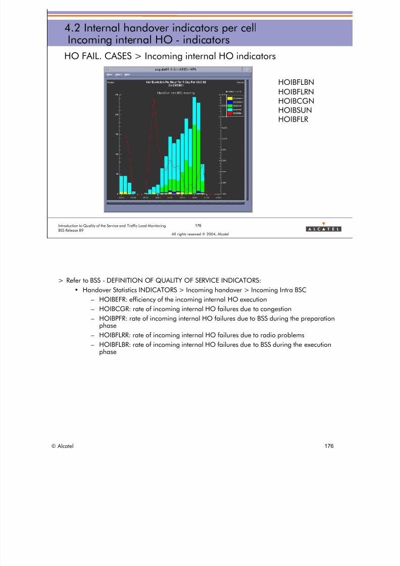
8/12/2019 QOS_B9 (Call Setup)
http://slidepdf.com/reader/full/qosb9-call-setup 176/388
176Introduction to Quality of the Service and Traffic Load MonitoringBSS Release B9
All rights reserved © 2004, Alcatel
4.2 Internal handover indicators per cellIncoming internal HO - indicators
HO FAIL. CASES > Incoming internal HO indicators
HOIBFLBNHOIBFLRNHOIBCGNHOIBSUNHOIBFLR
> Refer to BSS - DEFINITION OF QUALITY OF SERVICE INDICATORS:
• Handover Statistics INDICATORS > Incoming handover > Incoming Intra BSC
– HOIBEFR: efficiency of the incoming internal HO execution
– HOIBCGR: rate of incoming internal HO failures due to congestion
– HOIBPFR: rate of incoming internal HO failures due to BSS during the preparation
phase– HOIBFLRR: rate of incoming internal HO failures due to radio problems
– HOIBFLBR: rate of incoming internal HO failures due to BSS during the executionphase
© Alcatel 176
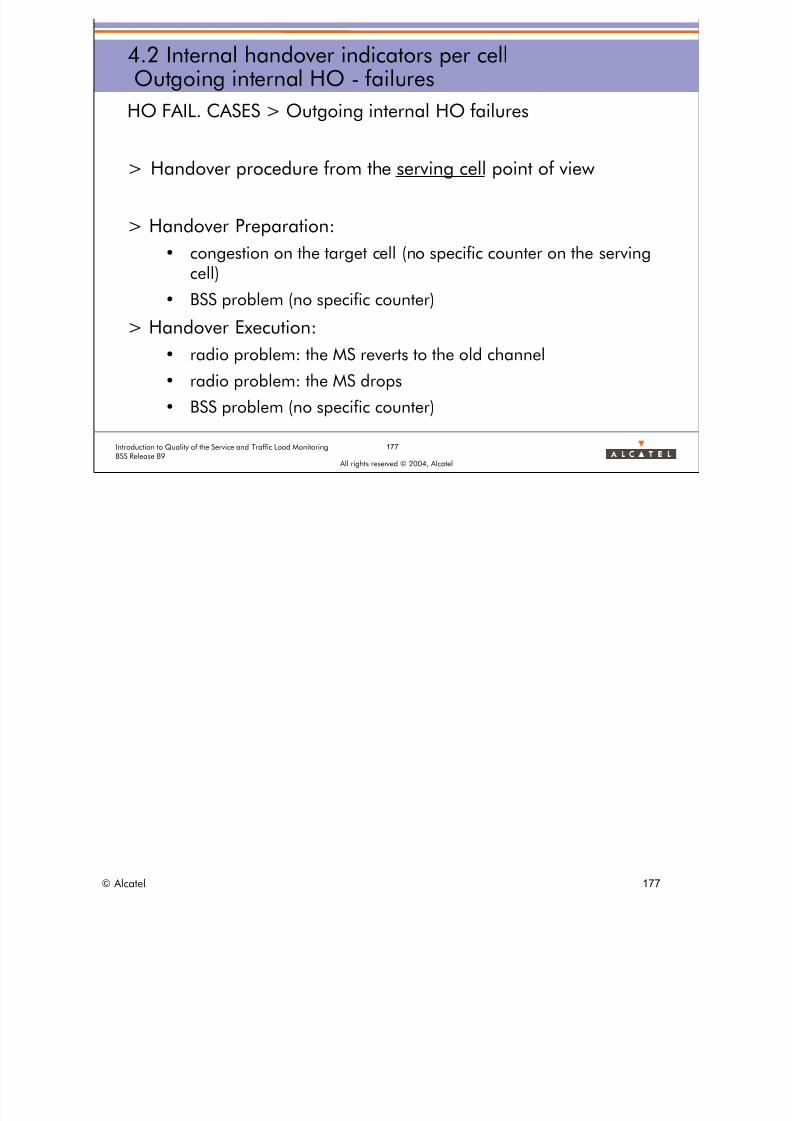
8/12/2019 QOS_B9 (Call Setup)
http://slidepdf.com/reader/full/qosb9-call-setup 177/388
177Introduction to Quality of the Service and Traffic Load MonitoringBSS Release B9
All rights reserved © 2004, Alcatel
4.2 Internal handover indicators per cellOutgoing internal HO - failures
HO FAIL. CASES > Outgoing internal HO failures
> Handover procedure from the serving cell point of view
> Handover Preparation:
• congestion on the target cell (no specific counter on the servingcell)
• BSS problem (no specific counter)
> Handover Execution:
• radio problem: the MS reverts to the old channel
• radio problem: the MS drops
• BSS problem (no specific counter)
© Alcatel 177
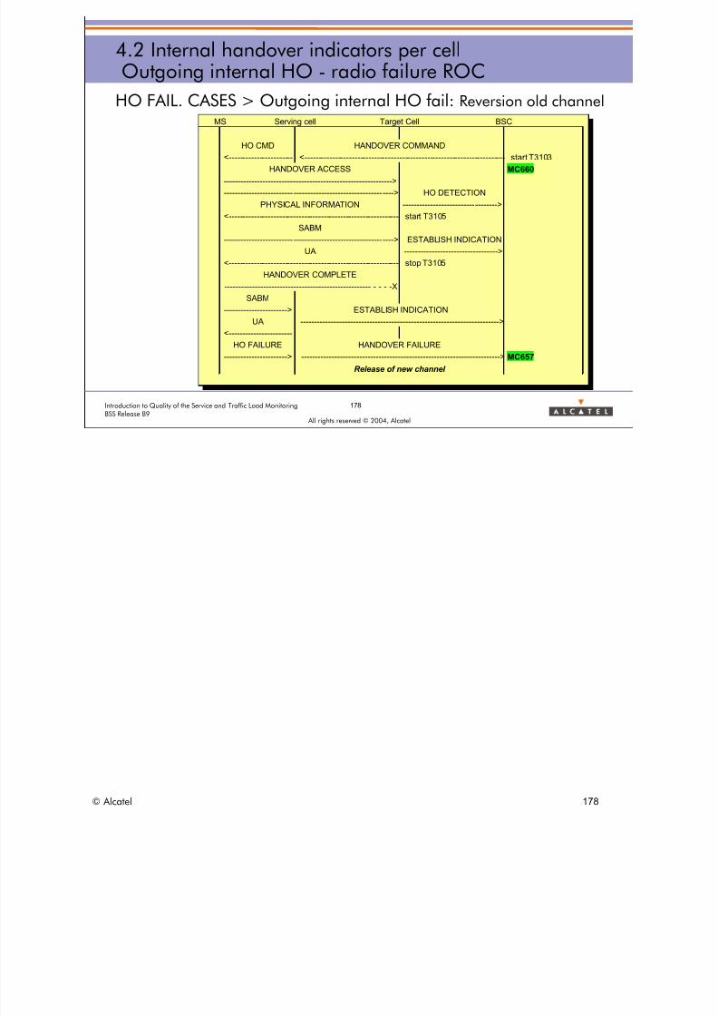
8/12/2019 QOS_B9 (Call Setup)
http://slidepdf.com/reader/full/qosb9-call-setup 178/388
178Introduction to Quality of the Service and Traffic Load MonitoringBSS Release B9
All rights reserved © 2004, Alcatel
4.2 Internal handover indicators per cellOutgoing internal HO - radio failure ROC
HO FAIL. CASES > Outgoing internal HO fail: Reversion old channelMS Serving cell Target Cell BSC
HO CMD HANDOVER COMMAND<---------------------- <----------------------------------------------------------------------- start T3103
HANDOVER ACCESS MC660
------------------------------------------------------------->
-------------------------------------------------------------> HO DETECTION
PHYSICAL INFORMATION ---------------------------------->
<------------------------------------------------------------ start T3105
SABM
-------------------------------------------------------------> ESTABLISH INDICATION
UA ---------------------------------->
<------------------------------------------------------------ stop T3105
HANDOVER COMPLETE
----------------------------------------------------- - - - -X
SABM
-----------------------> ESTABLISH INDICATION
UA ------------------------------------------------------------------------>
<----------------------
HO FAILURE HANDOVER FAILURE
-----------------------> ------------------------------------------------------------------------> MC657
Release of new channel
© Alcatel 178
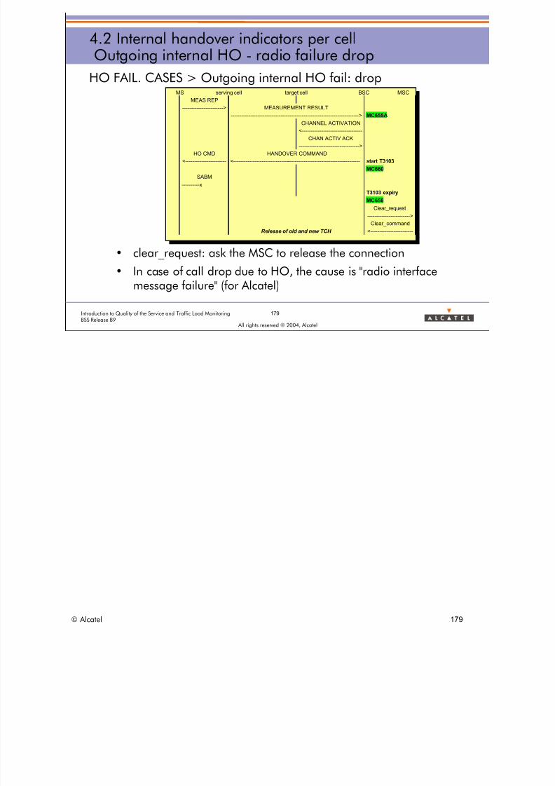
8/12/2019 QOS_B9 (Call Setup)
http://slidepdf.com/reader/full/qosb9-call-setup 179/388
179Introduction to Quality of the Service and Traffic Load MonitoringBSS Release B9
All rights reserved © 2004, Alcatel
4.2 Internal handover indicators per cellOutgoing internal HO - radio failure drop
HO FAIL. CASES > Outgoing internal HO fail: drop
• clear_request: ask the MSC to release the connection
• In case of call drop due to HO, the cause is "radio interfacemessage failure" (for Alcatel)
MS serving cell target cell BSC MSC
MEAS REP
-----------------------> MEASUREMENT RESULT
------------------------------------------------------------------------> MC655A
CHANNEL ACTIVATION
<---------------------------------
CHAN ACTIV ACK
---------------------------------->
HO CMD HANDOVER COMMAND
<---------------------- <----------------------------------------------------------------------- start T3103
MC660
SABM
----------x
T3103 expiry
MC658
Clear_request
------------------------>
Clear_commandRelease of old and new TCH <-----------------------
© Alcatel 179

8/12/2019 QOS_B9 (Call Setup)
http://slidepdf.com/reader/full/qosb9-call-setup 180/388
180Introduction to Quality of the Service and Traffic Load MonitoringBSS Release B9
All rights reserved © 2004, Alcatel
4.2 Internal handover indicators per cellOutgoing internal HO - counters
HO FAIL. CASES > Outgoing internal HO counters
Preparation Request MC655A
Any preparation failure MC655A-MC660
Attempt MC660
Reversion old channel MC657
Drop radio MC658
BSS Pb MC660-MC656-MC657-MC658
Success MC656
Execution
OUTGOING INTERNAL Handover
REQUEST
CONGESTION
ATTEMPT
REVERSION OLD CHANNEL
DROP RADIO
BSS PB
SUCCESS
BSS PB
Preparation Failure
Execution Failure
© Alcatel 180

8/12/2019 QOS_B9 (Call Setup)
http://slidepdf.com/reader/full/qosb9-call-setup 181/388
SUCCESS
181Introduction to Quality of the Service and Traffic Load MonitoringBSS Release B9
All rights reserved © 2004, Alcatel
4.2 Internal handover indicators per cellOutgoing internal HO - indicators
HO FAIL. CASES > Outgoing internal HO indicators
HOOBSUNHOOBCDRNHOOBCDBNHOOBOCNHOOBCDRHOOBOCR
> Refer to BSS - DEFINITION OF QUALITY OF SERVICE INDICATORS:
• Handover Statistics INDICATORS > Outgoing handover > Outgoing Intra BSC
– HOOBRQR: efficiency of the outgoing internal HO preparation.
– HOOBEFR: efficiency of the outgoing internal HO execution.
– HOOBOCR: rate of outgoing internal HO failures due to radio problems with
Reversion Old Channel.– HOOBCDRR: rate of outgoing internal HO failures due to radio problems with
drop.
– HOOBCDR: rate of incoming internal HO failures with drop (radio + BSS).
© Alcatel 181
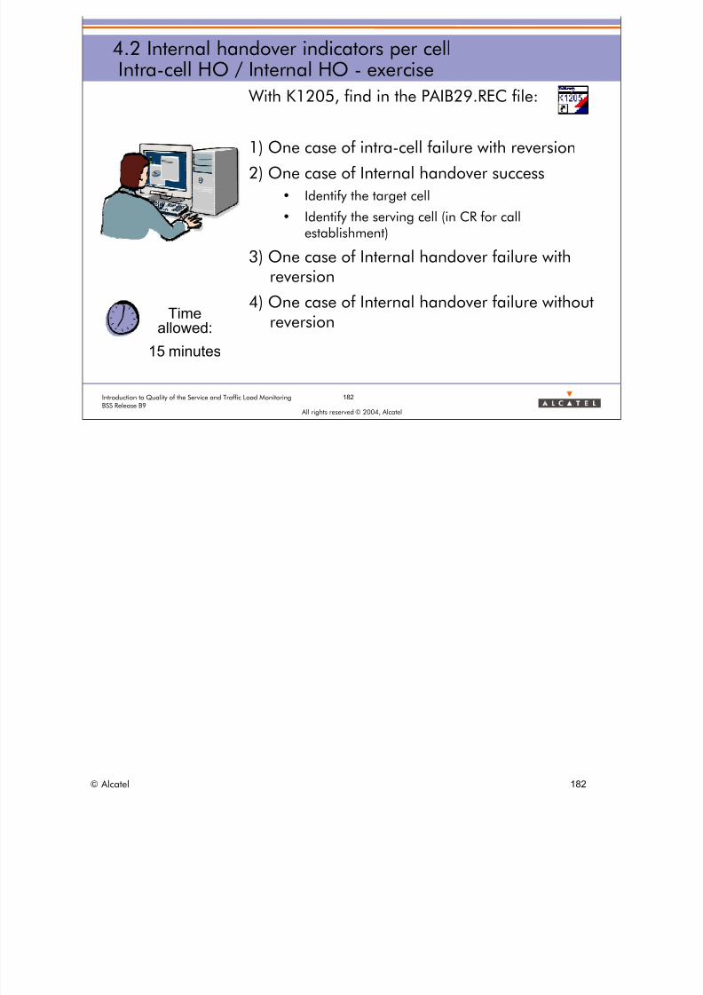
8/12/2019 QOS_B9 (Call Setup)
http://slidepdf.com/reader/full/qosb9-call-setup 182/388
182Introduction to Quality of the Service and Traffic Load MonitoringBSS Release B9
All rights reserved © 2004, Alcatel
4.2 Internal handover indicators per cellIntra-cell HO / Internal HO - exercise
With K1205, find in the PAIB29.REC file:
1) One case of intra-cell failure with reversion
2) One case of Internal handover success
• Identify the target cell
• Identify the serving cell (in CR for callestablishment)
3) One case of Internal handover failure withreversion
4) One case of Internal handover failure withoutreversion
Timeallowed:
15 minutes
© Alcatel 182

8/12/2019 QOS_B9 (Call Setup)
http://slidepdf.com/reader/full/qosb9-call-setup 183/388
All rights reserved © 2004, Alcatel
4 HANDOVER INDICATORS
4.3 External handover indicators per cell
© Alcatel 183

8/12/2019 QOS_B9 (Call Setup)
http://slidepdf.com/reader/full/qosb9-call-setup 184/388
184Introduction to Quality of the Service and Traffic Load MonitoringBSS Release B9
All rights reserved © 2004, Alcatel
4.3 External handover indicators per cellExternal HO - success
HO FAIL. CASES > External HO > successful case
MS serving_cell BSC MSC BSC target_cell MS- MEAS_REPORT ->
------- MEAS_RESULT -------->------ HO_REQUIRED ---------->
----------CR (HO_REQUEST) -----><--------- CC ----------------------- ---- CHANNEL_ACTIVATION ------>
<- CHANNEL_ACT_ACK------------<----- HO_REQUEST_ACK ------- Start T9113
(HO_COMMAND)<------------------------- HO_COMMAND ----------------------------------------------------- <---- HO_ACCESS ----
Start T8 <---- HO_ACCESS ----<------ HO_DETECTION-------------
<-- HO_DETECTION ------------- --- PHYSICAL_INFO -->
<--- SABM --------------<----- ESTABLISH_INDICATION --- ----- UA -------------->
<----------- HO_COMPLETE ---------------------------------------<--- HO_COMPLETE -------------- Stop T9113
<---- CLEAR_COMMAND -----Cause : HO_SUCCESSFUL
Release of TCH Stop T8
MC645AMC820
MC821
MC650
MC642MC646
MC462A
MC462B
MC462C
MC463A
MC463B
MC463C
> Both SDCCH and TCH are counted together.> From B7, MC645A replaces MC645 of B6.
> MC645a is only counting HANDOVER REQUIRED messages that are linked to a handover trial and not those that are linked to theupdate of the candidate cell list for handover / directed retry. This is leading to a more accurate computation of the Externaloutgoing HO success rate.Only Outgoing inter PLMN HO is allowed.
> 6 counters provide information for "Inter-PLMN HO" (Incoming and Outgoing) (From B8)
• MC462a (equivalent of MC645A for intra PLMN external HO)Number of inter-PLMN TCH outgoing handovers or directed retry requests:HANDOVER REQUIRED sent to the MSC for an external TCH HO or an external DR triggered towards a cell belonging to aPLMN different from the PLMN of the serving cell.
• MC462b (equivalent of MC650 for intra PLMN external HO)Number of inter-PLMN TCH outgoing handovers or directed retry attempts:HANDOVER COMMAND sent to the MS on Abis for an external TCH HO or an external DR triggered towards a cellbelonging to a PLMN different from the PLMN of the serving cell.
• MC462c (equivalent of MC646 for intra PLMN external HO)Number of inter-PLMN TCH outgoing handovers or directed retry successes:CLEAR COMMAND with Cause "Handover successful" received from the MSC for an external TCH HO or an external DRtriggered towards a cell belonging to a PLMN different from the PLMN of the serving cell.
• MC463a (equivalent of MC820 for intra PLMN external HO)Number of inter-PLMN TCH incoming handovers or directed retry requests:HANDOVER REQUEST received from the MSC for an external TCH HO or an external DR triggered towards the target cellfrom a serving cell belonging to a PLMN different from the PLMN of the target cell.
• MC463b (equivalent of MC821 for intra PLMN external HO)Number of inter-PLMN TCH incoming handovers or directed retry attempts:HANDOVER REQUEST ACK sent by the target BSC containing the HANDOVER COMMAND for an external TCH HO or anexternal DR triggered towards the target cell from a serving cell belonging to a PLMN different from the PLMN of the targetcell.
• MC463c (equivalent of MC642 for intra PLMN external HO)Number of inter-PLMN TCH incoming handovers or directed retry successes:HANDOVER COMPLETE received from the MS on Abis for an external TCH HO or an external DR triggered towards thetarget cell from a serving cell belonging to a PLMN different from the PLMN of the target cell.
> Note than all other (previous) counters related to HO continue to be based on Intra PLMN only .
© Alcatel 184

8/12/2019 QOS_B9 (Call Setup)
http://slidepdf.com/reader/full/qosb9-call-setup 185/388
185Introduction to Quality of the Service and Traffic Load MonitoringBSS Release B9
All rights reserved © 2004, Alcatel
4.3 External handover indicators per cellExternal HO - failures
HO FAIL. CASES > Incoming external HO failures
> Handover procedure from the target cell point of view
> Handover Preparation:
• congestion: no RTCH available in the target cell OR no TTCHavailable on the A interface
– does not concern the outgoing side (serving cell point of view)
• BSS problem (no specific counter)
> Handover Execution:
• radio problem: the MS fails to access the new channel
– the reversion/drop discrimination concerns only the serving cell
• BSS problem (no specific counter)
© Alcatel 185
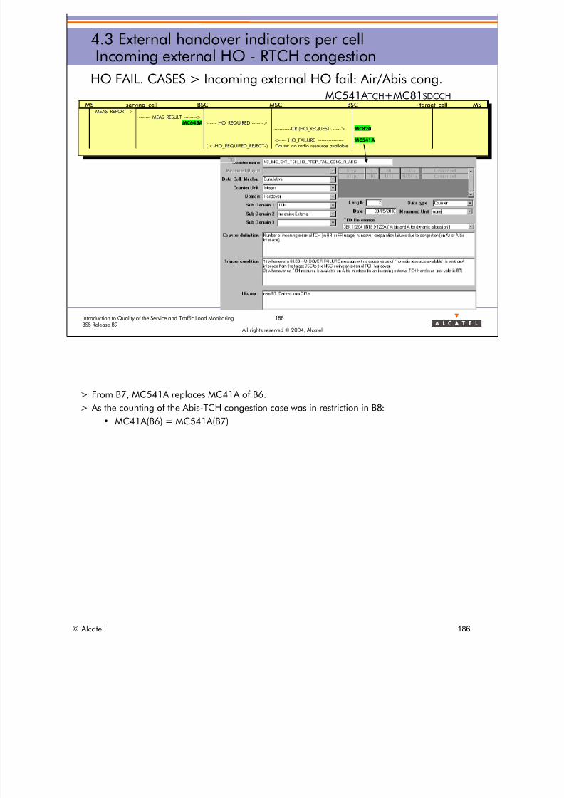
8/12/2019 QOS_B9 (Call Setup)
http://slidepdf.com/reader/full/qosb9-call-setup 186/388
186Introduction to Quality of the Service and Traffic Load MonitoringBSS Release B9
All rights reserved © 2004, Alcatel
4.3 External handover indicators per cellIncoming external HO - RTCH congestion
HO FAIL. CASES > Incoming external HO fail: Air/Abis cong.MC541A TCH+MC81SDCCH
MS serving_cell BSC MSC BSC target_cell MS- MEAS_REPORT ->
------- MEAS_RESULT -------->MC645A ------ HO_REQUIRED ------->
----------CR (HO_REQUEST) -----> MC820
<----- HO_FAILURE --------------- MC541A( <-HO_REQUIRED_REJECT- ) Cause: no radio resource available
> From B7, MC541A replaces MC41A of B6. > As the counting of the Abis-TCH congestion case was in restriction in B8:
• MC41A(B6) = MC541A(B7)
© Alcatel 186

8/12/2019 QOS_B9 (Call Setup)
http://slidepdf.com/reader/full/qosb9-call-setup 187/388
187ntroduction to Quality of the Service and Traffic Load Monitoring
>
BSS Release B9
4.3 External handover indicators per cellIncoming external HO - TTCH congestion
HO FAIL. CASES > Incoming external HO fail: A int. cong.
MC41B
MS serving_cell BSC MSC BSC target_cell MS- MEAS_REPORT ->
------- MEAS_RESULT -------->
MC645A ------ HO_REQUIRED ------->----------CR (HO_REQUEST) -----> MC820
<----- HO_FAILURE --------------- MC41BCause: terrestrial circuit already allocatedRequested terrestrial resource unaivalableBSS not equiopoed
( <-HO_REQUIRED_REJECT-)
All rights reserved © 2004, Alcatel
© Alcatel 187
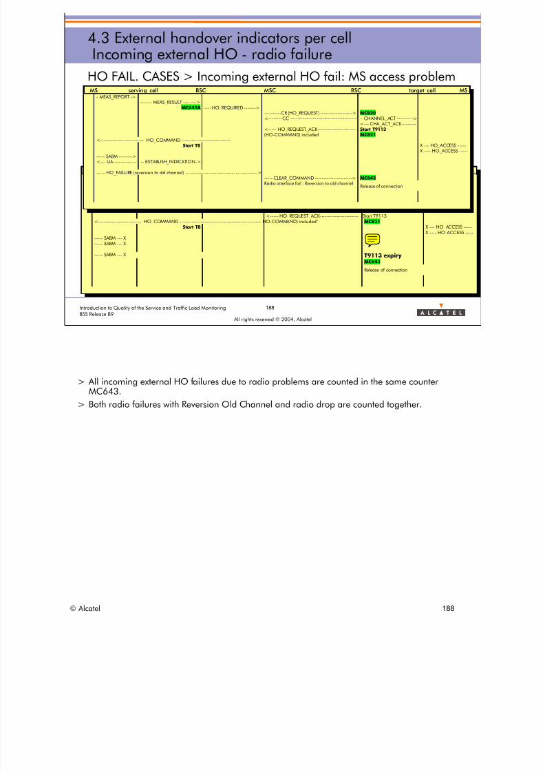
8/12/2019 QOS_B9 (Call Setup)
http://slidepdf.com/reader/full/qosb9-call-setup 188/388
MS serving cell BSC MSC BSC target cell MMEAS REPORT >
MEAS RESULT ->MC645A HO REQUIRED -->
CR HO REQUEST) -> MC82< - CC CHANNEL ACT >
< CHA ACT ACK
188Introduction to Quality of the Service and Traffic Load MonitoringBSS Release B9
All rights reserved © 2004, Alcatel
4.3 External handover indicators per cellIncoming external HO - radio failure
HO FAIL. CASES > Incoming external HO fail: MS access problem
_ _ S- _
------- _ ----------- _ -----
---------- _ ------------------------ --------------------------------------- - _ ---------
--- _ _ --------Start T9113
<----- HO_REQUEST_ACK---------------------- Start T9113
<-------------------------- HO_COMMAND ------------------------------------------------ HO-COMMAND) included° MC821Start T8 X --- HO_ACCESS ----
X ---- HO_ACCESS --------- SABM --- X----- SABM --- X
----- SABM --- X T9113 expiryMC643
Release of connection
MS serving_cell BSC MSC BSC target_cell MS- MEAS_REPORT ->
------- MEAS_RESULT -------->MC645A ---- HO_REQUIRED ------->
----------CR (HO_REQUEST) -------------------> MC820<-------- CC -------------------------------------- - CHANNEL_ACT ---------->
<--- CHA_ACT_ACK -------<----- HO_REQUEST_ACK---------------------- Start T9113(HO-COMMAND) included MC821
<-------------------------- HO_COMMAND ----------------------------- ------------------Start T8 X --- HO_ACCESS ----
X ---- HO_ACCESS --------- SABM --------><--- UA ------------ -- ESTABLISH_INDICATION->
----- HO_FAILURE (reversion to old channel) ----------------------------- ------------->----- CLEAR_COMMAND ----------------------> MC643Radio interface fail : Reversion to old channel
Release of connection
> All incoming external HO failures due to radio problems are counted in the same counterMC643.
> Both radio failures with Reversion Old Channel and radio drop are counted together.
© Alcatel 188
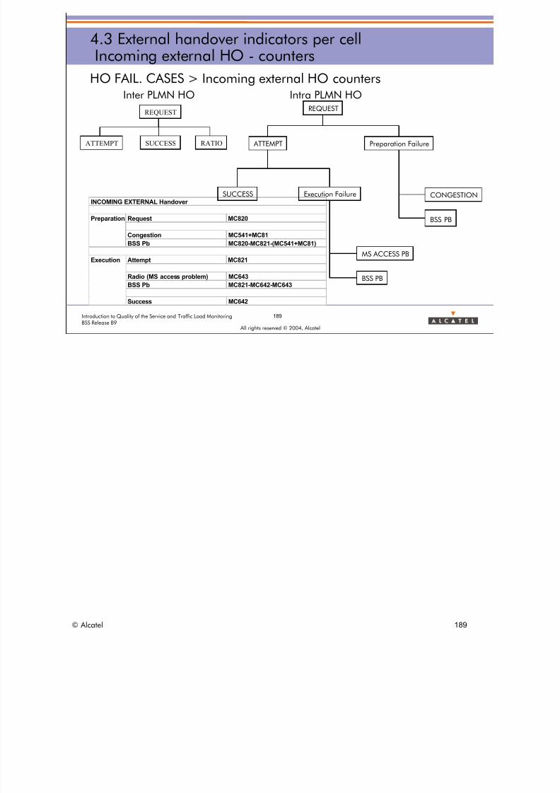
8/12/2019 QOS_B9 (Call Setup)
http://slidepdf.com/reader/full/qosb9-call-setup 189/388
189Introduction to Quality of the Service and Traffic Load MonitoringBSS Release B9
All rights reserved © 2004, Alcatel
4.3 External handover indicators per cellIncoming external HO - counters
HO FAIL. CASES > Incoming external HO countersInter PLMN HO Intra PLMN HO
Request MC820
Congestion MC541+MC81
BSS Pb MC820-MC821-(MC541+MC81)
Attempt MC821
Radio (MS access problem) MC643
BSS Pb MC821-MC642-MC643
Success MC642
Execution
Preparation
INCOMING EXTERNAL Handover
REQUEST
CONGESTION
ATTEMPT
MS ACCESS PB
BSS PB
SUCCESS
BSS PB
Preparation Failure
Execution Failure
ATTEMPT SUCCESS
REQUEST
RATIO
© Alcatel 189

8/12/2019 QOS_B9 (Call Setup)
http://slidepdf.com/reader/full/qosb9-call-setup 190/388
190Introduction to Quality of the Service and Traffic Load MonitoringBSS Release B9
All rights reserved © 2004, Alcatel
4.3 External handover indicators per cellIncoming external HO - indicators
HO FAIL. CASES > Incoming external HO indicators
HOIMFLBNHOIMFLRNHOIMCGNHOIMSUNHOIMFLR
> Refer to BSS - DEFINITION OF QUALITY OF SERVICE INDICATORS:
• Handover Statistics INDICATORS > Incoming handover > Incoming Inter BSC
– HOIMEFR: efficiency of the incoming external HO execution.
– HOIMCGR: rate of incoming external HO failures due to radio congestion (Air or Abis TCH).
– HOIMAMR: rate of incoming external HO failures due to CIC congestion (A TCH).
– HOIMPFR: rate of incoming external HO failures due to BSS during the preparation phase.
– HOIMFLRR: rate of incoming external HO failures due to radio problems.
– HOIMFLBR: rate of incoming external HO failures due to BSS during the execution phase.
> Inter PLMN Incoming External HO Indicators(from B8)
• An indicator is created for each counter.
– REQUESTS
– ATTEMPTS
– SUCCESS
• In addition, these indicators show:
– the success rate of incoming inter-PLMN HOs,
– the ratio of incoming inter-PLMN HO to incoming intra-PLMN and inter-PLMN HO,
© Alcatel 190

8/12/2019 QOS_B9 (Call Setup)
http://slidepdf.com/reader/full/qosb9-call-setup 191/388
191Introduction to Quality of the Service and Traffic Load MonitoringBSS Release B9
All rights reserved © 2004, Alcatel
4.3 External handover indicators per cellOutgoing external HO - failures
HO FAIL. CASES > Outgoing external HO failures
> Handover procedure from the serving cell point of view
> Handover Preparation:
• congestion on the target cell (no specific counter on the servingcell)
• BSS problem (no specific counter)
> Handover Execution:
• radio problem: the MS reverts to the old channel
• radio problem: the MS drops
• BSS problem (no specific counter)
© Alcatel 191

8/12/2019 QOS_B9 (Call Setup)
http://slidepdf.com/reader/full/qosb9-call-setup 192/388
192Introduction to Quality of the Service and Traffic Load MonitoringBSS Release B9
All rights reserved © 2004, Alcatel
4.3 External handover indicators per cellOutgoing external HO - radio failure ROC
HO FAIL. CASES > Outgoing external HO fail: reversion old channel
MS serving_cell BSC MSC BSC target_cell MS- MEAS_REPORT ->
------- MEAS_RESULT -------->MC645A ---- HO_REQUIRED ------->
----------CR (HO_REQUEST) -------------------><-------- CC -------------------------------------- - CHANNEL_ACT ---------->
<--- CHA_ACT_ACK -------<----- HO_REQUEST_ACK---------------------- Start T9113(HO-COMMAND) included
<-------------------------- HO_COMMAND -----------------------------------------------Start T8 X --- HO_ACCESS ----MC650 X ---- HO_ACCESS ----
----- SABM --------><--- UA ------------ -- ESTABLISH_INDICATION->
----- HO_FAILURE (reversion to old channel) ---------- ----------- ------------ --------->MC647 ----- CLEAR_COMMAND ---------------------->
Radio interface fail : Reversion to old channelRelease of connection
© Alcatel 192

8/12/2019 QOS_B9 (Call Setup)
http://slidepdf.com/reader/full/qosb9-call-setup 193/388
193Introduction to Quality of the Service and Traffic Load MonitoringBSS Release B9
All rights reserved © 2004, Alcatel
4.3 External handover indicators per cellOutgoing external HO - radio failure drop
HO FAIL. CASES > Outgoing external HO fail: drop
MS serving_cell BSC MSC BSC target_cell MS- MEAS_REPORT ->
------- MEAS_RESULT -------->MC645A ---- HO_REQUIRED ------->
----------CR (HO_REQUEST) -------------------><-------- CC -------------------------------------- - CHANNEL_ACT ---------->
<--- CHA_ACT_ACK -------<----- HO_REQUEST_ACK---------------------- Start T9113(HO-COMMAND) included
<-------------------------- HO_COMMAND --------- ----------- ---------- ----------- ------Start T8 X --- HO_ACCESS ----MC650 X ---- HO_ACCESS ----
----- SABM --- X----- SABM --- X
----- SABM --- X
T8 expiry ----- CLEAR_REQUEST ->MC648 Radio interface message fail
Release of connection
© Alcatel 193

8/12/2019 QOS_B9 (Call Setup)
http://slidepdf.com/reader/full/qosb9-call-setup 194/388
194Introduction to Quality of the Service and Traffic Load MonitoringBSS Release B9
All rights reserved © 2004, Alcatel
4.3 External handover indicators per cellOutgoing external HO - counters
HO FAIL. CASES > Outgoing external HO countersInter PLMN HO Intra PLMN HO
Preparation Request MC645A
Any preparation failure MC645A-MC650
Attempt MC650
Reversion old channel MC647
Drop radio MC648
BSS Pb MC650-MC646-MC647-MC648
Success MC646
Execution
OUTGOING EXTERNAL Handover
REQUEST
CONGESTION
ATTEMPT
REVERSION OLD CHANNEL
DROP RADIO
BSS PB
SUCCESS
BSS PB
Preparation Failure
Execution Failure
ATTEMPT SUCCESS
REQUEST
RATIO
© Alcatel 194

8/12/2019 QOS_B9 (Call Setup)
http://slidepdf.com/reader/full/qosb9-call-setup 195/388
195Introduction to Quality of the Service and Traffic Load MonitoringBSS Release B9
All rights reserved © 2004, Alcatel
4.3 External handover indicators per cellOutgoing external HO - indicators
HO FAIL. CASES > Outgoing external HO indicators
HOOMSUNHOOMCDRNHOOMCDBNHOOMOCNHOOMCDRHOOMOCR
> Refer to BSS - DEFINITION OF QUALITY OF SERVICE INDICATORS RELEASE:
• Handover Statistics INDICATORS > Outgoing handover > Outgoing Inter BSC
– HOOMRQR: efficiency of the outgoing external HO preparation.
– HOOMEFR: efficiency of the outgoing external HO execution.
– HOOMOCR: rate of outgoing external HO failures due to radio problems with Reversion OldChannel.
– HOOMCDRR: rate of outgoing external HO failures due to radio problems with drop.
– HOOMCDR: rate of incoming external HO failures with drop (radio + BSS).
> Inter PLMN Outgoing External HO Indicators (From B8)
• An indicator is created for each counter.
– REQUESTS
– ATTEMPTS
– SUCCESS
• In addition these indicators show:
– the success rate of outgoing inter-PLMN HOs,
– the ratio of outgoing inter-PLMN HO to outgoing intra-PLMN and inter-PLMN HO.
© Alcatel 195

8/12/2019 QOS_B9 (Call Setup)
http://slidepdf.com/reader/full/qosb9-call-setup 196/388
196Introduction to Quality of the Service and Traffic Load MonitoringBSS Release B9
All rights reserved © 2004, Alcatel
4.3 External handover indicators per cellExternal HO - exercise
In PAIB29.REC, extract (if available):
1) 1 incoming external HO success
2) 1 outgoing external HO success
3) 1 incoming external HO failure
4) 1 outgoing external HO failure
Time allowed:
15 minutes
© Alcatel 196

8/12/2019 QOS_B9 (Call Setup)
http://slidepdf.com/reader/full/qosb9-call-setup 197/388
All rights reserved © 2004, Alcatel
4 HANDOVER INDICATORS
4.4 Handover indicators per couple of cells
© Alcatel 197

8/12/2019 QOS_B9 (Call Setup)
http://slidepdf.com/reader/full/qosb9-call-setup 198/388
198Introduction to Quality of the Service and Traffic Load MonitoringBSS Release B9
All rights reserved © 2004, Alcatel
4.4 Handover indicators per couple of cellsType 180 counters
> Some handover indicators available per couple of (serving,target) cells:
• permanently through PM type 180 counters
3 counters for each (Serving,Target) adjacency:
C400(S,T): Incoming handovers requestedto cell T from cell S
C401(S,T): Incoming handovers attemptedto cell T from cell S
C402(S,T): Incoming handovers successfully performed to cell T from cell S
both internal and external inter cell handovers arecounted
both SDCCH and TCH handovers are counted
a
e
d
c
b
f
C40i(f,d)
C40i(a,b)C40i(c,b)
C40i(c,d)
> According to the definition of C40i counters:
• ∑C400(Sn,T) = MC820(T) + MC830(T)
• ∑C401(Sn,T) = MC821(T) +MC831(T)
• ∑C402(Sn,T) = MC642(T) + MC652(T)
– where
– Sn are the serving cells considering the incoming adjacencies to cell T.
– MC820(T), MC821(T), MC642(T) are the counters relating to the incomingexternal handovers requested, attempted and successfully performed to cell T.
– MC830(T), MC831(T), MC646(T) are the counters relating to the incominginternal handovers requested, attempted and successfully performed to cell T.
© Alcatel 198

8/12/2019 QOS_B9 (Call Setup)
http://slidepdf.com/reader/full/qosb9-call-setup 199/388
199Introduction to Quality of the Service and Traffic Load MonitoringBSS Release B9
All rights reserved © 2004, Alcatel
4.4 Handover indicators per couple of cellsType 180 indicators
The following indicators can be computed from PM Type 180counters in order to
> Detect the most important neighboring cells as per their traffic• Distribution of incoming handovers performed to cell T from serving cells
Sn = C402(Sx,T) / ∑C402(Sn,T)
> Ease the diagnosis of the bad handover performance of a cell
• Global efficiency of incoming handovers to cell T from cell S
HOOASUR = C402(S,T) / C400(S,T)
• Efficiency of the incoming handover preparation to cell T from cell S
HOOACAR = C401(S,T) / C400(S,T)• Efficiency of the incoming handover execution to cell T from cell S
HOOAEFR = C402(S,T) / C401(S,T)
n
> Refer to BSS - DEFINITION OF QUALITY OF SERVICE INDICATORS:
• Handover Statistics > HO Statistics per couple of cells > Indicators with counter type 180
– These indicators can also be to check if a recently handover relationship isgenerating handover as expected.
– They will also allow to identify the handover relationships which should be deleted
since no (or very few) handover is observed.
© Alcatel 199

8/12/2019 QOS_B9 (Call Setup)
http://slidepdf.com/reader/full/qosb9-call-setup 200/388
200Introduction to Quality of the Service and Traffic Load MonitoringBSS Release B9
All rights reserved © 2004, Alcatel
4.4 Handover indicators per couple of cellsType 26 counters
> Some handover indicators are available per couple of (serving,target) cells:
• on demand for all outgoing adjacencies of a serving cell throughPM type 26 (40 cells since B8)
Counters for each (Serving,Target x) adjacency:
C720(S,Tx): Outgoing handovers attemptedfrom cell S to cell Tx
C721(S,Tx): Outgoing handovers successfullyperformed from cell S to cell Tx
C722(S,Tx): Outgoing handovers failed fromcell S to cell Tx with Reversion Old Channel
C723(S,Tx): Outgoing handovers failed fromcell S to cell Tx with drop
Target a
Te
Serving
Tc
Tb
Tf
C72i(S,Te)
C72i(S,Tc)
> Other counters are provided:
• C724(S,Tx): Outgoing handovers attempted from S to Tx for an emergency cause.
• C725(S,Tx): Outgoing handovers attempted from S to Tx for a better cell cause.
• C727(S,Tx): Outgoing handovers attempted from S to Tx for a traffic cause.
• C728(S,Tx): Outgoing handovers attempted from S to Tx for a forced directed retry
cause.> Previously the set of Type 26 counters could be retrieved for only one cell per BSS at once.
> 40 cells at the same time since B8.
© Alcatel 200

8/12/2019 QOS_B9 (Call Setup)
http://slidepdf.com/reader/full/qosb9-call-setup 201/388
201Introduction to Quality of the Service and Traffic Load MonitoringBSS Release B9
All rights reserved © 2004, Alcatel
4.4 Handover indicators per couple of cellsType 26 indicators
The following indicators can be computed from PM Type 26counters (40 cells since B8) in order to:
> ease the diagnosis of the bad outgoing handover performanceof a cell
• Efficiency of the outgoing handover execution from cell S to cell TxHOOXSUR = C721(S,Tx) / C720(S,Tx)
• Rate of outgoing ho execution failures due to radio problems fromS to Tx with drop
HOOXCDRR = C723(S,Tx) / C720(S,Tx)
• Rate of outgoing ho execution failures due to radio problems from
S to Tx with Reversion Old ChannelHOOXOCR = C722(S,Tx) / C720(S,Tx)
• Rate of outgoing ho execution failures due to BSS problems fromS to Tx
HOOXCDBR = [C720(S,Tx)-C721(S,Tx)-C722(S,Tx)-C723(S,Tx)] /C720(S,Tx)
> Refer to BSS - DEFINITION OF QUALITY OF SERVICE INDICATORS:
• Handover Statistics > HO Statistics per couple of cells > Indicators with counter type 26.
• From B8, these type 26 counters are available for several cells at once (40 cells).
© Alcatel 201
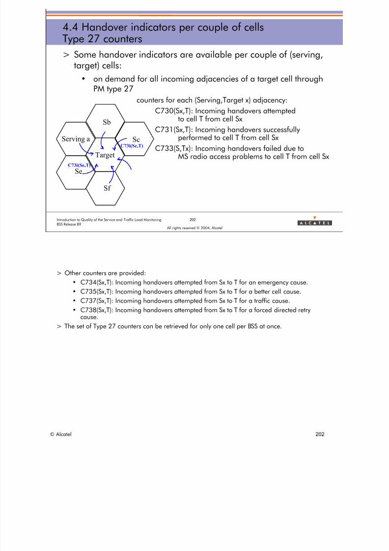
8/12/2019 QOS_B9 (Call Setup)
http://slidepdf.com/reader/full/qosb9-call-setup 202/388
202Introduction to Quality of the Service and Traffic Load MonitoringBSS Release B9
All rights reserved © 2004, Alcatel
4.4 Handover indicators per couple of cellsType 27 counters
> Some handover indicators are available per couple of (serving,target) cells:
• on demand for all incoming adjacencies of a target cell throughPM type 27
counters for each (Serving,Target x) adjacency:
C730(Sx,T): Incoming handovers attemptedto cell T from cell Sx
C731(Sx,T): Incoming handovers successfullyperformed to cell T from cell Sx
C733(S,Tx): Incoming handovers failed due to
MS radio access problems to cell T from cell Sx
Serving a
Se
Target
Sc
Sb
Sf
C73i(Se,T)
C73i(Sc,T)
> Other counters are provided:
• C734(Sx,T): Incoming handovers attempted from Sx to T for an emergency cause.
• C735(Sx,T): Incoming handovers attempted from Sx to T for a better cell cause.
• C737(Sx,T): Incoming handovers attempted from Sx to T for a traffic cause.
• C738(Sx,T): Incoming handovers attempted from Sx to T for a forced directed retry
cause.> The set of Type 27 counters can be retrieved for only one cell per BSS at once.
© Alcatel 202

8/12/2019 QOS_B9 (Call Setup)
http://slidepdf.com/reader/full/qosb9-call-setup 203/388
203Introduction to Quality of the Service and Traffic Load MonitoringBSS Release B9
All rights reserved © 2004, Alcatel
4.4 Handover indicators per couple of cellsType 27 indicators
The following indicators can be computed from PM Type 27counters in order to
> Ease the diagnosis of the bad incoming handover performanceof a cell
• Efficiency of the incoming handover execution to cell T from cellSx
HOIXSUR = C731(Sx,T) / C730(Sx,T)
• Rate of incoming ho execution failures due to MS radio accessproblems to cell T from cell Sx
HOIXCDRR = C733(Sx,T) / C730(Sx,T)
• Rate of incoming ho execution failures due to BSS problems to cellT from cell Sx
HOIXCDBR= [C730(Sx,T)-C731(Sx,T)-C733(Sx,T)] / C730(Sx,T)
> Refer to BSS - DEFINITION OF QUALITY OF SERVICE INDICATORS:
• Handover Statistics > HO Statistics per couple of cells > Indicators with counter type 27
© Alcatel 203

8/12/2019 QOS_B9 (Call Setup)
http://slidepdf.com/reader/full/qosb9-call-setup 204/388
All rights reserved © 2004, Alcatel
5 DIRECTED RETRY INDICATORS
© Alcatel 204

8/12/2019 QOS_B9 (Call Setup)
http://slidepdf.com/reader/full/qosb9-call-setup 205/388
205Introduction to Quality of the Service and Traffic Load MonitoringBSS Release B9
All rights reserved © 2004, Alcatel
5 Directed retry indicatorsSession presentation
> Objective: to be able to describe the counters and indicators
used for monitoring the efficiency of the directed retry feature
> Program:
• 5.1 Directed Retry definition
© Alcatel 205

8/12/2019 QOS_B9 (Call Setup)
http://slidepdf.com/reader/full/qosb9-call-setup 206/388
All rights reserved © 2004, Alcatel
5 DIRECTED RETRY INDICATORS
5.1 Directed Retry definition
© Alcatel 206
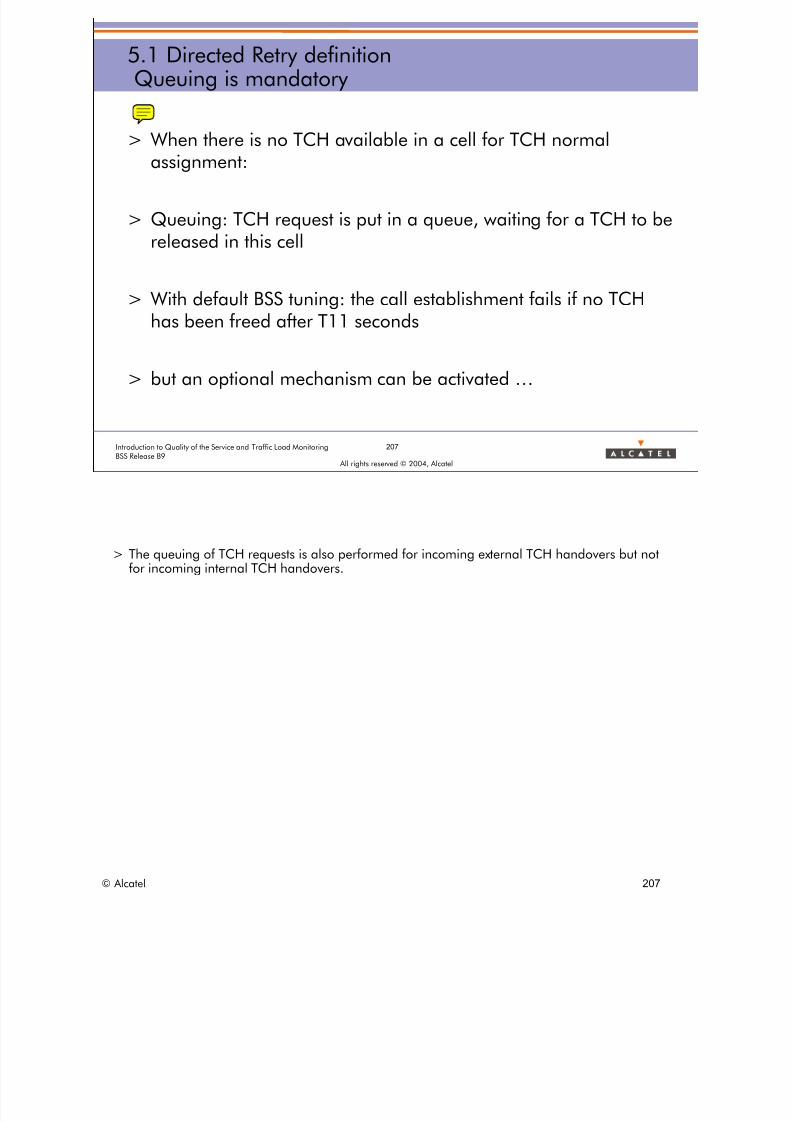
8/12/2019 QOS_B9 (Call Setup)
http://slidepdf.com/reader/full/qosb9-call-setup 207/388
207Introduction to Quality of the Service and Traffic Load MonitoringBSS Release B9
All rights reserved © 2004, Alcatel
5.1 Directed Retry definitionQueuing is mandatory
> When there is no TCH available in a cell for TCH normal
assignment:
> Queuing: TCH request is put in a queue, waiting for a TCH to bereleased in this cell
> With default BSS tuning: the call establishment fails if no TCH
has been freed after T11 seconds
> but an optional mechanism can be activated …
> The queuing of TCH requests is also performed for incoming external TCH handovers but notfor incoming internal TCH handovers.
© Alcatel 207
8/12/2019 QOS_B9 (Call Setup)
http://slidepdf.com/reader/full/qosb9-call-setup 208/388
208Introduction to Quality of the Service and Traffic Load MonitoringBSS Release B9
All rights reserved © 2004, Alcatel
5.1 Directed Retry definitionNormal and Forced Directed Retry
Directed Retry (DR): When a TCH request is in queue, the BSC
tries to establish the TCH connection on a neighboring cell if:
> the normal handover condition is met (Normal DR)
> specific directed retry conditions are met (Forced DR):
• the MS receives a sufficient signal level from a neighboring cell
• the number of free TCHs in this neighboring cell is sufficient
© Alcatel 208

8/12/2019 QOS_B9 (Call Setup)
http://slidepdf.com/reader/full/qosb9-call-setup 209/388
209Introduction to Quality of the Service and Traffic Load MonitoringBSS Release B9
All rights reserved © 2004, Alcatel
5.1 Directed Retry definitionDirected Retry types
DR FAIL. CASES > DR Reminder
DR as an SDCCH to TCH handovercan be
> Internal
• between two cells of the sameBSC
• also called intra BSC
> External
• between two cells of differentBSCs
• also called inter BSC
> Incoming
• as considering the target cell
> Outgoing
• as considering the serving cell
> Synchronous
• between 2 cells• sharing the same clocks
• collocated
• usually 2 sectors of the sameBTS
– tunable at OMC-R level
> Asynchronous
• not synchronous for anyreason
• no dedicated monitoring forsynchronous/asynchronousHO
ANNEX 3
> There is no Intracell Directed Retry contrary to HO:
> An Intracell Directed is a Call Setup !! !-)
> Please refer to Annex for Directed Retry counters details
© Alcatel 209

8/12/2019 QOS_B9 (Call Setup)
http://slidepdf.com/reader/full/qosb9-call-setup 210/388
All rights reserved © 2004, Alcatel
6 RADIO MEASUREMENT STATISTICSINDICATORS
© Alcatel 210
8/12/2019 QOS_B9 (Call Setup)
http://slidepdf.com/reader/full/qosb9-call-setup 211/388
211Introduction to Quality of the Service and Traffic Load MonitoringBSS Release B9
All rights reserved © 2004, Alcatel
6 Radio Measurement Statistics indicatorsSession presentation
> Objective: to be able to describe the RMS indicators used for
radio quality assessment of a TRX or cell and to use them in thedetection of some typical radio problems
> Program:
• 6.1 Radio Measurement Statistics objectives
• 6.2 RMS implementation in the BSS
• 6.3 RMS data
• 6.4 Call quality statistics per TRX
• 6.5 Radio quality statistics per TRX• 6.6 C/I statistics
• 6.7 RMS indicators usage
• 6.8 Additional information
© Alcatel 211

8/12/2019 QOS_B9 (Call Setup)
http://slidepdf.com/reader/full/qosb9-call-setup 212/388
All rights reserved © 2004, Alcatel
6 RADIO MEASUREMENT STATISTICSINDICATORS
6.1 Radio Measurement Statistics objectives
© Alcatel 212
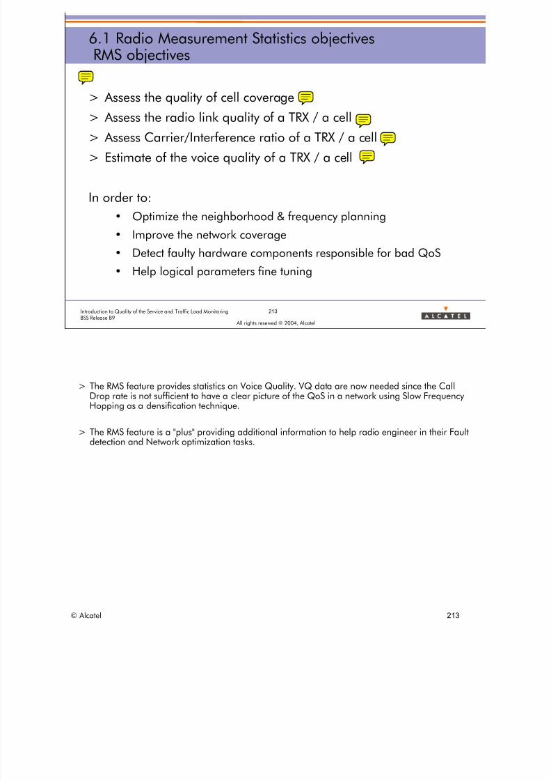
8/12/2019 QOS_B9 (Call Setup)
http://slidepdf.com/reader/full/qosb9-call-setup 213/388
213Introduction to Quality of the Service and Traffic Load MonitoringBSS Release B9
All rights reserved © 2004, Alcatel
6.1 Radio Measurement Statistics objectivesRMS objectives
> Assess the quality of cell coverage
> Assess the radio link quality of a TRX / a cell
> Assess Carrier/Interference ratio of a TRX / a cell
> Estimate of the voice quality of a TRX / a cell
In order to:
• Optimize the neighborhood & frequency planning
• Improve the network coverage
• Detect faulty hardware components responsible for bad QoS
• Help logical parameters fine tuning
> The RMS feature provides statistics on Voice Quality. VQ data are now needed since the CallDrop rate is not sufficient to have a clear picture of the QoS in a network using Slow FrequencyHopping as a densification technique.
> The RMS feature is a "plus" providing additional information to help radio engineer in their Faultdetection and Network optimization tasks.
© Alcatel 213

8/12/2019 QOS_B9 (Call Setup)
http://slidepdf.com/reader/full/qosb9-call-setup 214/388
214Introduction to Quality of the Service and Traffic Load MonitoringBSS Release B9
All rights reserved © 2004, Alcatel
6.1 Radio Measurement Statistics objectivesRMS objectives
> Provide Radio Measurement Statistics
• On all the network elements (all TRXs/cells)
• Permanently through the PM type 31
– RMS results available every day (after a specific period)
In order to
• Reduce the cost of Radio Network Optimization
> Today's solutions for Radio Measurements are limited and very expensive:
• drive tests: provide a mobile user with the perception of the network but cannot be doneon the whole network and on an very day basis since:
– they are costly (tool+car+manpower).
– they need to be post-processed.
– they are limited to part of the network.– they are available on the DownLink path only.
• Abis interface traces: provide a complete Uplink and Downlink radio quality assessmentof a cell but cannot be done on the whole network and on an every day basis since:
– they are costly (protocol analyzer+manpower).
– they need to be post-processed.
– they are limited to a few cells at once per analyzer.
© Alcatel 214

8/12/2019 QOS_B9 (Call Setup)
http://slidepdf.com/reader/full/qosb9-call-setup 215/388
All rights reserved © 2004, Alcatel
6 RADIO MEASUREMENT STATISTICSINDICATORS
6.2 RMS implementation in the BSS
© Alcatel 215

8/12/2019 QOS_B9 (Call Setup)
http://slidepdf.com/reader/full/qosb9-call-setup 216/388
216Introduction to Quality of the Service and Traffic Load MonitoringBSS Release B9
All rights reserved © 2004, Alcatel
6.2 RMS implementation in the BSSRMS management
> RMS results are reported permanently (once a day) by the BSS as
a PM Type 31 counters to the OMC-R
> The RMS job is defined and activated on a per BSS basis
> RMS job parameters are managed through RMS templates
• RMS templates provide means to tune RMS parameters according
to Cell Planning (cell profile, cell class)
> The cell profile can be: micro, indoor, multiband, etc. > The cell class can be: rural, urban, rural rapid (covering express railway), etc. > Templates parameters define the intervals or Received level, Consecutive frame erasure, Radio
link counter, Path balance, C/I …for which RMS counters are provided.
© Alcatel 216

8/12/2019 QOS_B9 (Call Setup)
http://slidepdf.com/reader/full/qosb9-call-setup 217/388
Templat
217Introduction to Quality of the Service and Traffic Load MonitoringBSS Release B9
All rights reserved © 2004, Alcatel
6.2 RMS implementation in the BSSRMS configuration in the OMC-R
RMS with OMC-R only
> Templates are defined on theOMC-R
> RMS results are retrieved once aday from the BSC
> Binary files can be exported forpost-processing
PM
RMS in binary filesesTemplates
© Alcatel 217

8/12/2019 QOS_B9 (Call Setup)
http://slidepdf.com/reader/full/qosb9-call-setup 218/388
218Introduction to Quality of the Service and Traffic Load MonitoringBSS Release B9
All rights reserved © 2004, Alcatel
6.2 RMS implementation in the BSSRMS configuration in RNO
RMS with OMC-R, NPA & RNO
> Templates are defined on RNO
> RMS results are retrieved once a day
from the BSC> Binary files are transferred to NPA
> RMS warnings on NPA
> RMS QoS reports on RNO
> RMS reports used in RNO
• Check
• QoS follow-up
• Diagnosis
• Tuning
> The Experience matrix can begenerated for network planning
> Excel export is adapted to RMS
Benefit to whole RNO
Templates
PMCompute
experiencematrix
> The cell profile can be: micro, indoor, multiband, etc. > The cell class can be: rural, urban, rural rapid (covering express railway), etc.
© Alcatel 218

8/12/2019 QOS_B9 (Call Setup)
http://slidepdf.com/reader/full/qosb9-call-setup 219/388
em pl te
219Introduction to Quality of the Service and Traffic Load MonitoringBSS Release B9
All rights reserved © 2004, Alcatel
6.2 RMS implementation in the BSSRMS data flow
RNO defines and sendsRMS templates to the OMC-R
The OMC-R activates an RMS campaignin the BSS
RMS counters are transferred tothe OMC
RMS counters arestored in NPA
RMS indicators
requested by RNORMS QOS reportdisplayed
RNO calculates and exports theExperience matrix to RNP
1
2
3
4
5
7
6
A9156 RNO
NPA
RNP
OMC-R
BSS
1
Experience matrix
7
PM4
2PM
3
QOS
6
QOS
> RNO is able to define the templates for the RMS jobs and helps in defining the MAFA frequencies.
• The tuning function of RNO defines a preferred RMS template depending on cell characteristics (type,class, capacity, etc.).
• RNO manages the frequencies to monitor through MAFA jobs depending on the neighborhood and thefrequency bands.
> RNO is a reference for RMS templates:
• 16 templates stored in the RNO database,
• Reference values for templates available,
• Extra editor in the administration tool to modify templates:
– a given value or a reference one.
> NPA
• NPA stores RMS jobs measurements, at Cell & TRX levels (15 days).
• NPA makes some consolidations (voice quality, averages, etc.).
• NPA manages some warnings on RMS indicators (path balance).
> The Experience Matrix generated by RNO is an interference matrix computed from C/I measurements providedthrough RMS counters.
© Alcatel 219
8/12/2019 QOS_B9 (Call Setup)
http://slidepdf.com/reader/full/qosb9-call-setup 220/388
220Introduction to Quality of the Service and Traffic Load MonitoringBSS Release B9
All rights reserved © 2004, Alcatel
6.2 RMS implementation in the BSSRMS data presentation
> In all this chapter
• System parameters (user tuneable or not) will always be written inBLUE BOLD FONT
• Indicators and counters will be typedin ITALIC and underline
© Alcatel 220

8/12/2019 QOS_B9 (Call Setup)
http://slidepdf.com/reader/full/qosb9-call-setup 221/388
All rights reserved © 2004, Alcatel
6 RADIO MEASUREMENT STATISTICSINDICATORS
6.3 RMS data
© Alcatel 221

8/12/2019 QOS_B9 (Call Setup)
http://slidepdf.com/reader/full/qosb9-call-setup 222/388
222Introduction to Quality of the Service and Traffic Load MonitoringBSS Release B9
All rights reserved © 2004, Alcatel
6.3 RMS dataRMS data presentation
> 3 main RMS statistics types
• Call Quality Statistics which qualify calls according to
coverage/interference criteria– based on samples corresponding to measurement results averagedover a number of SACCH multi-frames
• Radio Quality Statistics:– UL/DL level, UL/DL qual
– CFE
– AMR (Analyse the coded values)
– Timing Advance
• C/I Statistics on neighboring freq/MAFA freq– last 2 statistics types based on samples corresponding to
measurement results Annex 1
B9
B9
B9
> The first RMS Statistics type is based on calls.
> The two others are based on TRX/Cell.
> additional information• Measurement results, TRX, BS/MS max power
> MAFA = Mobile Assisted Frequency Allocation is a GSM Phase 2+ feature allowing torequest a mobile to measure and report through Extended Measurement Report message aC/I value for each frequency specified in an Extended Measurement Order message.
> CFE: Consecutive Frame Erasure
> 1 SACCH multi-frame (SACCH mfr) corresponds to 4 consecutive sequences of 26 TDMAframes during which, in the uplink, a measurement report message is received by the BTSfrom the MS.
© Alcatel 222

8/12/2019 QOS_B9 (Call Setup)
http://slidepdf.com/reader/full/qosb9-call-setup 223/388
All rights reserved © 2004, Alcatel
6 RADIO MEASUREMENT STATISTICSINDICATORS
6.4 Call quality statistics per TRX
© Alcatel 223

8/12/2019 QOS_B9 (Call Setup)
http://slidepdf.com/reader/full/qosb9-call-setup 224/388
All rights reserved © 2004, Alcatel
6 RADIO MEASUREMENT STATISTICSINDICATORS
6.4 Call quality statistics per TRX6.4.1 Generalities
© Alcatel 224
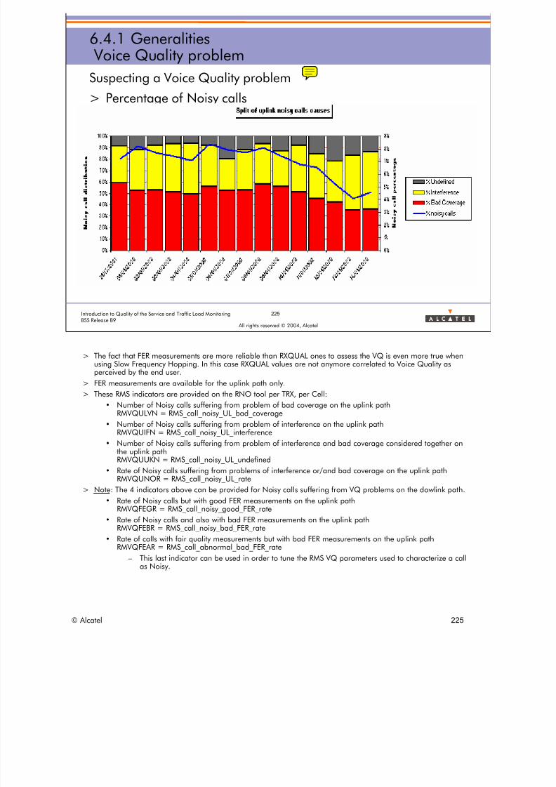
8/12/2019 QOS_B9 (Call Setup)
http://slidepdf.com/reader/full/qosb9-call-setup 225/388
225Introduction to Quality of the Service and Traffic Load MonitoringBSS Release B9
All rights reserved © 2004, Alcatel
6.4.1 Generalities Voice Quality problem
Suspecting a Voice Quality problem
> Percentage of Noisy calls
> The fact that FER measurements are more reliable than RXQUAL ones to assess the VQ is even more true whenusing Slow Frequency Hopping. In this case RXQUAL values are not anymore correlated to Voice Quality asperceived by the end user.
> FER measurements are available for the uplink path only.
> These RMS indicators are provided on the RNO tool per TRX, per Cell:
• Number of Noisy calls suffering from problem of bad coverage on the uplink path RMVQULVN = RMS_call_noisy_UL_bad_coverage
• Number of Noisy calls suffering from problem of interference on the uplink path RMVQUIFN = RMS_call_noisy_UL_interference
• Number of Noisy calls suffering from problem of interference and bad coverage considered together on
the uplink pathRMVQUUKN = RMS_call_noisy_UL_undefined
• Rate of Noisy calls suffering from problems of interference or/and bad coverage on the uplink pathRMVQUNOR = RMS_call_noisy_UL_rate
> Note: The 4 indicators above can be provided for Noisy calls suffering from VQ problems on the dowlink path.
• Rate of Noisy calls but with good FER measurements on the uplink path RMVQFEGR = RMS_call_noisy_good_FER_rate
• Rate of Noisy calls and also with bad FER measurements on the uplink path RMVQFEBR = RMS_call_noisy_bad_FER_rate
• Rate of calls with fair quality measurements but with bad FER measurements on the uplink pathRMVQFEAR = RMS_call_abnormal_bad_FER_rate
– This last indicator can be used in order to tune the RMS VQ parameters used to characterize a call
as Noisy.
© Alcatel 225

8/12/2019 QOS_B9 (Call Setup)
http://slidepdf.com/reader/full/qosb9-call-setup 226/388
226Introduction to Quality of the Service and Traffic Load MonitoringBSS Release B9
All rights reserved © 2004, Alcatel
6.4.1 GeneralitiesCall Quality measurements
VQ_AVERAGE = 4 SACCH AV_RXLEV_UL_VQ = (RxlevUL1+RxlevUL2+RxlevUL3+RxlevUL4) / 4
AV_RXLEV_DL_VQ = (RxlevDL1+RxlevDL2+RxlevDL3+RxlevDL4) / 4
AV_RXQUAL_UL_VQ = (RxqualUL1+RxqualUL2+RxqualUL3+RxqualUL4) / 4
AV_RXQUAL_DL_VQ = (RxqualDL1+RxqualDL2+RxqualDL3+RxqualDL4) / 4
AV_RXFER_UL_VQ = (Nb of speech frames wrongly decoded (BFI=1)/ Total nb of speech frames of the CQS)
Average level, quality and FER of a Call Quality Sample
SACCH meas.begin end
CALL
480ms
CQS1 CQS2 CQS3 CQS4 CQS5 CQS6 CQS7 CQS8 CQS9 CQS10 CQS11 CQS12 CQS13 CQS14 CQS15 CQS16CQS375
1 measurement report⇔
1 SACCH mfr
> CQS: Call Quality Sample
> VQ_AVERAGE = Number of consecutive SACCH measurements from which the reported Leveland Quality notes (UL and DL) are averaged. The resulting averages represent the level andquality of the corresponding Call Quality Sample, i.e. the portion of the call over which leveland quality have been measured.
> AV_RXLEV_xx_VQ = Average xx level measured over a Call Quality Sample (VQ_AVERAGESACCH)
> AV_RXQUAL_xx_VQ = Average xx quality measured over a Call Quality Sample(VQ_AVERAGE SACCH)
© Alcatel 226

8/12/2019 QOS_B9 (Call Setup)
http://slidepdf.com/reader/full/qosb9-call-setup 227/388
227Introduction to Quality of the Service and Traffic Load MonitoringBSS Release B9
All rights reserved © 2004, Alcatel
6.4.1 GeneralitiesClassification of a CQS and Noisy Call identification
How to qualify the quality of a call? By looking at the repartition of the CQS!:
quality
Level (dBm)
7
0
-110 -47VQ_RXLEV
bad quality + good level
interfered CQS
bad quality & level
bad coverage CQS
VQ_RXQUAL
CQS
> VQ_RXLEV = radio level threshold to classify a CQS as bad coverage CQS. > VQ_RXQUAL = radio quality threshold to classify a CQS as bad coverage CQS. > VQ_INTF_THRESHOLD = Ratio of bad CQS (interference or bad coverage) to classify a Call as
Noisy.
> A call is classify as:
• Noisy xx Interference if Ratio of xx interfered CQS > VQ_INTF_THRESHOLD• Noisy xx Coverage if Ratio of xx bad coverage CQS > VQ_INTF_THRESHOLD
• Noisy xx Undefined if Ratio of (xx interfered CQS + xx bad coverage CQS) > VQ_INTF_THRESHOLD
© Alcatel 227

8/12/2019 QOS_B9 (Call Setup)
http://slidepdf.com/reader/full/qosb9-call-setup 228/388
All rights reserved © 2004, Alcatel
6 RADIO MEASUREMENT STATISTICSINDICATORS
6.4 Call quality statistics per TRX6.4.2 Call quality parameters
© Alcatel 228
8/12/2019 QOS_B9 (Call Setup)
http://slidepdf.com/reader/full/qosb9-call-setup 229/388
229Introduction to Quality of the Service and Traffic Load MonitoringBSS Release B9
All rights reserved © 2004, Alcatel
6.4.2 Call quality parametersRMS parameters
Call Quality Statistics:Parameters used to determine if a call is noisy (according toRXQUAL) and of bad voice quality (according to FER)
> VQ_AVERAGE: averaging window size on measurement resultsto obtain Call Quality Samples (CQSs) (0 SACCH mfr to 128Smf)
> VQ_RXLEV : radio level threshold to specify a bad coverageCQS for noisy call statistics (-110 to -65 dBm)
> VQ_RXQUAL: radio quality threshold to specify a bad quality(RXQUAL) CQS for noisy call statistics (0 to 7)
> VQ_RXQUAL_VS_RXFER: radio quality threshold to specify abad or a good quality CQS correlated to bad or good FERmeasurements for noisy call statistics (0 to 7)
> All these parameters are included in the RMS PM Type 31 result files as RMS counters:
• RMSpc = PAR_VQ_AVERAGE
• RMSpd = PAR_VQ_RXLEV
• RMSpe = PAR_VQ_RXQUAL
• RMSpf = PAR_VQ_RXQUAL_VS_RXFER
> Call Quality Sample (A CQS) will be qualified as “of bad level” if the Average RxLevel is lowerthan VQ_RXLEV
> A CQS will be qualified as “of bad quality” if the Average RxQuality is greater than VQ_RXQUAL
> For FER counters, VQ_RXQUAL_VS_RXFER is used instead of VQ_RXQUAL to qualify a CQS as“of bad quality” if the Average FER is also checked (compared to VQ_xx_RXFER).
> Note: For CQS, the averaging process is non-sliding.
© Alcatel 229

8/12/2019 QOS_B9 (Call Setup)
http://slidepdf.com/reader/full/qosb9-call-setup 230/388
230Introduction to Quality of the Service and Traffic Load MonitoringBSS Release B9
All rights reserved © 2004, Alcatel
6.4.2 Call quality parametersRMS parameters
Call Quality Statistics
> VQ_GOOD_RXFER: Frame Erasure Rate threshold to specify agood FER CQS for noisy call statistics (0 to 20%)
> VQ_BAD_RXFER: FER threshold to specify a bad FER CQS fornoisy call statistics (0 to 20%)
> VQ_INTF_THRESHOLD: Call Quality Samples threshold tocharacterize a call as noisy (0 to 100%)
> VQ_FER_THRESHOLD: Call Quality Samples threshold tocharacterize a call as “of bad or good” voice quality (0 to 100%)
> All these parameters are included in the RMS PM Type 31 result files as RMS counters:
• RMSpg = PAR_VQ_GOOD_RXFER
• RMSph = PAR_VQ_ BAD_RXFER
• RMSpi = PAR_VQ_INTF_THRESHOLD
• RMSpj = PAR_VQ_FER_THRESHOLD
© Alcatel 230
8/12/2019 QOS_B9 (Call Setup)
http://slidepdf.com/reader/full/qosb9-call-setup 231/388
All rights reserved © 2004, Alcatel
6 RADIO MEASUREMENT STATISTICSINDICATORS
6.4 Call quality statistics per TRX
6.4.3 Call quality counters
© Alcatel 231
8/12/2019 QOS_B9 (Call Setup)
http://slidepdf.com/reader/full/qosb9-call-setup 232/388
232Introduction to Quality of the Service and Traffic Load MonitoringBSS Release B9
All rights reserved © 2004, Alcatel
6.4.3 Call quality countersRMS counters (1/4)
> VQ_NOISY_UL_INTERFERENCE = RMS10Number of calls suffering from interference problem on the
uplink path
> VQ_NOISY_UL_INTERFERENCE is incremented whenever a callverifies:
100*(INTERFERED_UL_SAMPLES / NUM_UL_SAMPLES) > VQ_INTF_THRESHOLD
• withINTERFERED_UL_SAMPLES = nb of times where
AV_RXQUAL_UL_VQ > VQ_RXQUALand AV_RXLEV_UL_VQ> VQ_RXLEV
> Call Quality Statistics counters are related only to speech channels.
Considering: AV_RXQUAL_UL_VQ: average on VQ_AVERAGE measurements of RXQUAL_UL
AV_RXLEV_UL_VQ: average on VQ_AVERAGE measurements of RXLEV_UL
NUM_UL_SAMPLES: total number of averages calculated on UL measurements during thecall on the considered TRX
© Alcatel 232

8/12/2019 QOS_B9 (Call Setup)
http://slidepdf.com/reader/full/qosb9-call-setup 233/388
233Introduction to Quality of the Service and Traffic Load MonitoringBSS Release B9
All rights reserved © 2004, Alcatel
6.4.3 Call quality countersRMS counters (2/4)
> VQ_NOISY_UL_INTERFERENCE = RMS10Number of calls suffering from interference problem on the
uplink path> VQ_NOISY_DL_INTERFERENCE = RMS11
Number of calls suffering from interference problem on thedownlink path
> VQ_NOISY_UL_COVERAGE = RMS12Number of calls suffering from bad coverage problem on the
uplink path
> VQ_NOISY_DL_COVERAGE = RMS13Number of calls suffering from bad coverage problem on the
downlink path
> RMS10 = VQ_NOISY_UL_INTERFERENCE is incremented whenever a call verifies:100*(INTERFERED_UL_SAMPLES / NUM_UL_SAMPLES) > VQ_INTF_THRESHOLD
with INTERFERED_UL_SAMPLES = nb of times when AV_RXQUAL_UL_VQ > VQ_RXQUAL and AV_RXLEV_UL_VQ>VQ_RXLEV
considering AV_RXQUAL_UL_VQ: average on VQ_AVERAGE measurements of RXQUAL_UL AV_RXLEV_UL_VQ: average on VQ_AVERAGE measurements of RXLEV_UL
NUM_UL_SAMPLES: total number of averages calculated on UL measurements during the call on theconsidered TRX
> RMS11 = VQ_NOISY_DL_INTERFERENCE is incremented whenever a call verifies:100*(INTERFERED_DL_SAMPLES / NUM_DL_SAMPLES) > VQ_INTF_THRESHOLD
with INTERFERED_DL_SAMPLES = nb of times when AV_RXQUAL_DL_VQ > VQ_RXQUAL and AV_RXLEV_DL_VQ>VQ_RXLEV
considering AV_RXQUAL_DL_VQ: average on VQ_AVERAGE measurements of RXQUAL_DL AV_RXLEV_DL_VQ: average on VQ_AVERAGE measurements of RXLEV_DL
NUM_DL_SAMPLES: total number of averages calculated on DL measurements during the call on theconsidered TRX
> RMS12 = VQ_NOISY_UL_COVERAGE is incremented whenever a call verifies:100*(BAD_COVERAGE_UL_SAMPLES / NUM_UL_SAMPLES) > VQ_INTF_THRESHOLD
with BAD_COVERAGE_UL_SAMPLES = nb of times when AV_RXQUAL_UL_VQ > VQ_RXQUAL and AV_RXLEV_UL_VQ<=VQ_RXLEV
> RMS13 = VQ_NOISY_DL_COVERAGE is incremented whenever a call verifies:100*(BAD_COVERAGE_DL_SAMPLES / NUM_DL_SAMPLES) > VQ_INTF_THRESHOLD
with BAD_COVERAGE_DL_SAMPLES = nb of times when AV_RXQUAL_DL_VQ > VQ_RXQUAL and AV_RXLEV_DL_VQ<=VQ_RXLEV
© Alcatel 233

8/12/2019 QOS_B9 (Call Setup)
http://slidepdf.com/reader/full/qosb9-call-setup 234/388
234Introduction to Quality of the Service and Traffic Load MonitoringBSS Release B9
All rights reserved © 2004, Alcatel
6.4.3 Call quality countersRMS counters (3/4)
> VQ_NOISY_UL_UNDEFINED = RMS14Number of calls suffering from both problems of interference
and bad coverage on the uplink path• These calls are not counted in VQ_NOISY_UL_COVERAGE or
VQ_NOISY_UL_INTERFERENCE
> VQ_NOISY_DL_UNDEFINED = RMS15Number of calls suffering from both problems of interference
and bad coverage on the downlink path
• These calls are not counted in VQ_NOISY_DL_COVERAGE or VQ_NOISY_DL_INTERFERENCE
> RMS14 = VQ_NOISY_UL_UNDEFINED is incremented whenever a call verifies:100*(BAD_COVERAGE_UL_SAMPLES / NUM_UL_SAMPLES) <= VQ_INTF_THRESHOLDand 100*(INTERFERED_UL_SAMPLES / NUM_UL_SAMPLES) <= VQ_INTF_THRESHOLDand 100*(BAD_QUALITY_UL_SAMPLES / NUM_UL_SAMPLES) > VQ_INTF_THRESHOLD
withBAD_COVERAGE_UL_SAMPLES = nb of times when AV_RXQUAL_UL_VQ > VQ_RXQUAL and AV_RXLEV_UL_VQ<=VQ_RXLEV
INTERFERED_UL_SAMPLES = nb of times when AV_RXQUAL_UL_VQ > VQ_RXQUALand AV_RXLEV_UL_VQ > VQ_RXLEV
BAD_QUALITY_UL_SAMPLES = INTERFERED_UL_SAMPLES + BAD_COVERAGE_UL_SAMPLES= nb of times when AV_RXQUAL_UL_VQ > VQ_RXQUAL
> RMS15 = VQ_NOISY_DL_UNDEFINED is incremented whenever a call verifies:100*(BAD_COVERAGE_DL_SAMPLES / NUM_DL_SAMPLES) <= VQ_INTF_THRESHOLDand 100*(INTERFERED_DL_SAMPLES / NUM_DL_SAMPLES) <= VQ_INTF_THRESHOLDand 100*(BAD_QUALITY_DL_SAMPLES / NUM_DL_SAMPLES) > VQ_INTF_THRESHOLD
withBAD_COVERAGE_DL_SAMPLES = nb of times when AV_RXQUAL_DL_VQ > VQ_RXQUALand AV_RXLEV_DL_VQ<=VQ_RXLEV
INTERFERED_DL_SAMPLES = nb of times when AV_RXQUAL_DL_VQ > VQ_RXQUALand AV_RXLEV_DL_VQ > VQ_RXLEV
BAD_QUALITY_DL_SAMPLES = INTERFERED_DL_SAMPLES + BAD_COVERAGE_DL_SAMPLES= nb of times when AV_RXQUAL_DL_VQ > VQ_RXQUAL
© Alcatel 234

8/12/2019 QOS_B9 (Call Setup)
http://slidepdf.com/reader/full/qosb9-call-setup 235/388
235Introduction to Quality of the Service and Traffic Load MonitoringBSS Release B9
All rights reserved © 2004, Alcatel
6.4.3 Call quality countersRMS counters (4/4)
> VQ_NOISY_UL_BAD_FER = RMS16Number of calls with bad quality measurements and with bad
FER measurements on the uplink path• Bad quality means bad RXQUAL whatever RXLEV is
> VQ_NOISY_UL_GOOD_FER = RMS17Number of calls with bad quality measurements but with
good FER measurements on the uplink path
> VQ_ABNORMAL_BAD_FER = RMS18Number of calls with fair quality measurements but with bad
FER measurements on the uplink path
> RMS16 = VQ_NOISY_UL_BAD_FER is incremented whenever a call verifies:100*(BAD_QUALITY_UL_SAMPLES / NUM_UL_SAMPLES) > VQ_INTF_THRESHOLDand 100*(BAD_QUAL_BAD_FER_UL_SAMPLES / BAD_QUALITY_UL_SAMPLES) > VQ_FER_THRESHOLD
with BAD_QUALITY_UL_SAMPLES = INTERFERED_UL_SAMPLES + BAD_COVERAGE_UL_SAMPLES = nb of times when AV_RXQUAL_UL_VQ > VQ_RXQUAL BAD_QUAL_BAD_FER_UL_SAMPLES = nb of times when AV_RXQUAL_UL_VQ > VQ_RXQUAL_VS_RXFER and AV_RXFER_UL_VQ > VQ_BAD_RXFER
considering AV_RXFER_UL_VQ: average on VQ_AVERAGE measurements of FER
> RMS17 = VQ_NOISY_UL_GOOD_FER is incremented whenever a call verifies:100*(BAD_QUALITY_UL_SAMPLES / NUM_UL_SAMPLES) > VQ_INTF_THRESHOLDand 100*(BAD_QUAL_GOOD_FER_UL_SAMPLES / BAD_QUALITY_UL_SAMPLES) > VQ_FER_THRESHOLD
with BAD_QUALITY_UL_SAMPLES = INTERFERED_UL_SAMPLES + BAD_COVERAGE_UL_SAMPLES = nb of times when AV_RXQUAL_UL_VQ > VQ_RXQUAL BAD_QUAL_GOOD_FER_UL_SAMPLES = nb of times when AV_RXQUAL_UL_VQ > VQ_RXQUAL_VS_RXFER and AV_RXFER_UL_VQ <= VQ_GOOD_RXFER
> RMS18 = VQ_ABNORMAL_BAD_FER is incremented whenever a call verifies:100*(FAIR_QUAL_BAD_FER_UL_SAMPLES / FAIR_QUALITY_UL_SAMPLES) > VQ_FER_THRESHOLD
withFAIR_QUALITY_UL_SAMPLES = nb of times when AV_RXQUAL_UL_VQ < VQ_RXQUAL_VS_RXFER
FAIR_QUAL_BAD_FER_UL_SAMPLES = nb of times when AV_RXQUAL_UL_VQ<VQ_RXQUAL_VS_RXFER and AV_RXFER_UL_VQ>VQ_BAD_RXFER
© Alcatel 235

8/12/2019 QOS_B9 (Call Setup)
http://slidepdf.com/reader/full/qosb9-call-setup 236/388
All rights reserved © 2004, Alcatel
6 RADIO MEASUREMENT STATISTICSINDICATORS
6.5 Radio quality statistics per TRX
© Alcatel 236

8/12/2019 QOS_B9 (Call Setup)
http://slidepdf.com/reader/full/qosb9-call-setup 237/388
All rights reserved © 2004, Alcatel
6 RADIO MEASUREMENT STATISTICSINDICATORS
6.5 Radio quality statistics per TRX
6.5.1 Generalities
© Alcatel 237
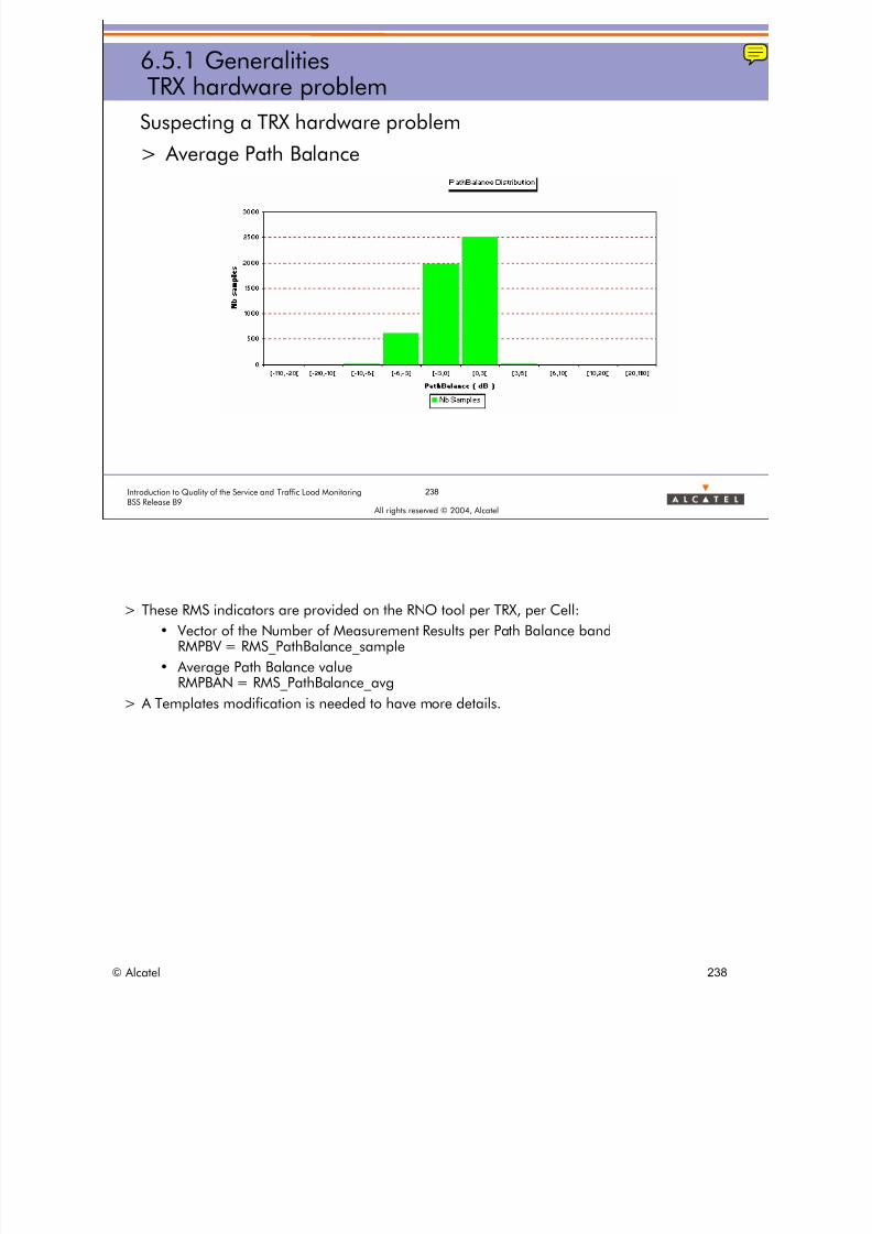
8/12/2019 QOS_B9 (Call Setup)
http://slidepdf.com/reader/full/qosb9-call-setup 238/388
238Introduction to Quality of the Service and Traffic Load MonitoringBSS Release B9
All rights reserved © 2004, Alcatel
6.5.1 GeneralitiesTRX hardware problem
Suspecting a TRX hardware problem
> Average Path Balance
> These RMS indicators are provided on the RNO tool per TRX, per Cell:
• Vector of the Number of Measurement Results per Path Balance bandRMPBV = RMS_PathBalance_sample
• Average Path Balance value RMPBAN = RMS_PathBalance_avg
> A Templates modification is needed to have more details.
© Alcatel 238

8/12/2019 QOS_B9 (Call Setup)
http://slidepdf.com/reader/full/qosb9-call-setup 239/388
239Introduction to Quality of the Service and Traffic Load MonitoringBSS Release B9
All rights reserved © 2004, Alcatel
6.5.1 Generalities Vector counter
RMS7a=TPR_PATH_BALANCE RMS7b= MAX_PATH_BALANCE
> The real number of Measurement Results in which Path balanceis in PATH BALANCE band j is equal to:
• S(PATH BALANCE band j) x Max / 254
• TPR_PATH_BALANCE(j) x MAX_PATH_BALANCE / 254
> The vector counter system is used to provide:
• Path balance repartition
• Radio Link counter (Consecutive Frame Erasure) repartition
• C/I repartition
• AMR FR/HR/DL/UL usage repartition• TA repartition (improved)
© Alcatel 239

8/12/2019 QOS_B9 (Call Setup)
http://slidepdf.com/reader/full/qosb9-call-setup 240/388
240Introduction to Quality of the Service and Traffic Load MonitoringBSS Release B9
All rights reserved © 2004, Alcatel
Suspecting a cell coverage problem
> Distribution of samples per RxQual value and RxLev band
> Distribution of samples per RxLev band
6.5.1 GeneralitiesCell coverage problem
> A coverage problem is observed when a significant amount of the traffic of a cell is sufferingfrom both low level and bad quality (RxQual).
> To confirm the distribution of samples per RXLEV band, should also be considered to know theproportion of calls which are experiencing a low signal level.
> If a lot of samples of low level and bad quality are observed for only a sub-part of the TRXs (canbe one only) then a BTS hardware problem or a problem on the aerials should be suspected.
> If all the TRXs are experiencing a lot of samples of low level and bad quality then a coverageproblem shall be suspected.
> These RMS indicators are provided on the RNO tool per TRX, per Cell:
• Matrix of Number of Measurement Results per DL RxQual value and per DL RxLev bandRMQLDSAM = RMS_DL_RxQuality_RxLevel_sample
• Vector of Percentage of Samples per DL RxLev band RMQLDLVDV = RMS_DL_RxLevel_distrib
• Vector of Percentage of Samples per DL RxQual band RMQLDQUDV = RMS_DL_RxQuality_distrib
© Alcatel 240

8/12/2019 QOS_B9 (Call Setup)
http://slidepdf.com/reader/full/qosb9-call-setup 241/388
241Introduction to Quality of the Service and Traffic Load MonitoringBSS Release B9
All rights reserved © 2004, Alcatel
6.5.1 GeneralitiesMatrix counter
TPR_RXQUAL_UL_RXLEV_ULTPR_RXQUAL_UL_RXLEV_UL TMR_RXQUAL_UL_RXLEV_ULTMR_RXQUAL_UL_RXLEV_UL
> This counter RMS3a=TPR_RXQUAL_UL_RXLEV_UL is a matrix
– represented on the left side
> This counter RMS3b=TMR_RXQUAL_UL_RXLEV_UL is a vector
– represented on the right side
> The real number of Measurement Results in which UL RxQual is equal to i and UL
RxLev is in RXLEV band j, is equal to :
• S(RXQUAL i, RXLEV band j) x Max j / 254
• TPR_RXQUAL_UL_RXLEV_UL(i,j) x TMR_RXQUAL_UL_RXLEV_UL(j) / 254
© Alcatel 241

8/12/2019 QOS_B9 (Call Setup)
http://slidepdf.com/reader/full/qosb9-call-setup 242/388
All rights reserved © 2004, Alcatel
6 RADIO MEASUREMENT STATISTICSINDICATORS
6.5 Radio quality statistics per TRX6.5.2 Radio quality parameters
© Alcatel 242

8/12/2019 QOS_B9 (Call Setup)
http://slidepdf.com/reader/full/qosb9-call-setup 243/388
243Introduction to Quality of the Service and Traffic Load MonitoringBSS Release B9
All rights reserved © 2004, Alcatel
6.5.2 Radio quality parametersRMS parameters (1/4)
Radio Quality Statistics:Parameters used to define intervals for RXLEV, Path Balance,
Radio Link Counter and Consecutive Frame Erasure, TA statisticsNo parameters needed for AMR measurements (counters, see later)
> MEAS_STAT_LEV1 to MEAS_STAT_LEV9:9 thresholds on the received radio level value defining 10
RXLEV bands
-110 ≤MEAS_STAT_LEV(i+1) ≤MEAS_STAT_LEV(i) < -47 dBm
> MEAS_STAT_PATH_BAL1 to MEAS_STAT_PATH_BAL9:9 thresholds on the radio signal propagation loss difference
between UL and DL defining 10 Path Balance bands-110< MEAS_STAT_PATHBAL(i) ≤MEAS_STAT_PATHBAL(i+1) ≤+110 dB
B9
B9
> All these parameters are included in the RMS PM Type 31 result files as RMS counters:
• RMSpt5 = TAB_PAR_MEAS_LEV = Table of 9 parameters MEAS_STAT_LEVi
• RMSpt4 = TAB_PAR_MEAS_PATH_BALANCE = Table of 9 parameters MEAS_STAT_PATH_BALi
> The Path Balance is computed by the BTS from each Measurement Result message as the difference between:
• Path loss on the uplink: received level by the BTS - MS power level
• Path loss on the downlink: received level by the MS - BS power level
– where the BTS power level is computed as the BTS nominal power minus by the BTS power relative level.
> Therefore the Path balance is computed as follows:
• Path Balance = (RXLEV_UL - MS_TXPWR)- (RXLEV_DL - [BTS_MAX_OUTPUT_POWER - abs(BS_TXPWR)])
– where
– RXLEV_UL is the received signal levels measured by the BTS on the uplink path (in dBm).
– MS_TXPWR is the MS transmitted power converted by the BTS from the MS power level into dBmvalue according to the frequency band of the TRX.
– BS_TXPWR is the BTS transmitted power offset defined relatively to the maximum absolute outputpower of the BTS (negative value in dB).
– BTS_MAX_OUTPUT_POWER is the maximum power of the BTS after Combiner (in dBm).
– RXLEV_DL is the received signal levels measured by the MS on the downlink path (in dBm).
> NOTE: Additional asymetric DL loss (external combiner) or UL gain (TMA) are not taken into account in thecomputation, so they must be considered when interpreting the RMS results.
© Alcatel 243
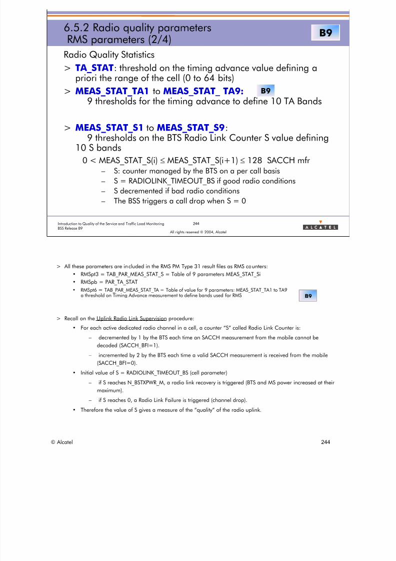
8/12/2019 QOS_B9 (Call Setup)
http://slidepdf.com/reader/full/qosb9-call-setup 244/388
244Introduction to Quality of the Service and Traffic Load MonitoringBSS Release B9
All rights reserved © 2004, Alcatel
6.5.2 Radio quality parametersRMS parameters (2/4)
Radio Quality Statistics
> TA_STAT: threshold on the timing advance value defining a
priori the range of the cell (0 to 64 bits)> MEAS_STAT_TA1 to MEAS_STAT_ TA9:
9 thresholds for the timing advance to define 10 TA Bands
> MEAS_STAT_S1 to MEAS_STAT_S9:9 thresholds on the BTS Radio Link Counter S value defining
10 S bands
0 < MEAS_STAT_S(i) ≤MEAS_STAT_S(i+1) ≤128 SACCH mfr– S: counter managed by the BTS on a per call basis
– S = RADIOLINK_TIMEOUT_BS if good radio conditions
– S decremented if bad radio conditions
– The BSS triggers a call drop when S = 0
B9
B9
> All these parameters are included in the RMS PM Type 31 result files as RMS counters:
• RMSpt3 = TAB_PAR_MEAS_STAT_S = Table of 9 parameters MEAS_STAT_Si
• RMSpb = PAR_TA_STAT
• RMSpt6 = TAB_PAR_MEAS_STAT_TA = Table of value for 9 parameters: MEAS_STAT_TA1 to TA9 a threshold on Timing Advance measurement to define bands used for RMS B9
> Recall on the Uplink Radio Link Supervision procedure:
• For each active dedicated radio channel in a cell, a counter “S” called Radio Link Counter is:
– decremented by 1 by the BTS each time an SACCH measurement from the mobile cannot be
decoded (SACCH_BFI=1).
– incremented by 2 by the BTS each time a valid SACCH measurement is received from the mobile
(SACCH_BFI=0).
• Initial value of S = RADIOLINK_TIMEOUT_BS (cell parameter)
– if S reaches N_BSTXPWR_M, a radio link recovery is triggered (BTS and MS power increased at their
maximum).
– if S reaches 0, a Radio Link Failure is triggered (channel drop).
• Therefore the value of S gives a measure of the “quality” of the radio uplink.
© Alcatel 244
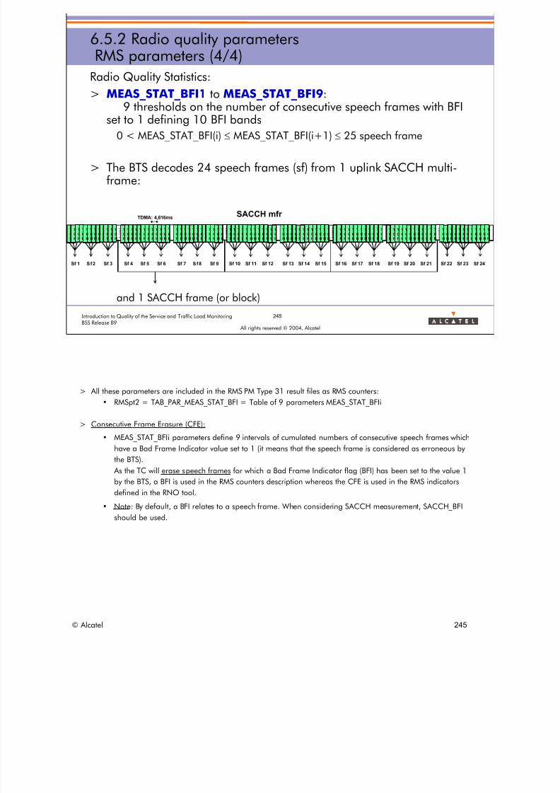
8/12/2019 QOS_B9 (Call Setup)
http://slidepdf.com/reader/full/qosb9-call-setup 245/388
245Introduction to Quality of the Service and Traffic Load MonitoringBSS Release B9
All rights reserved © 2004, Alcatel
6.5.2 Radio quality parametersRMS parameters (4/4)
Radio Quality Statistics:
> MEAS_STAT_BFI1 to MEAS_STAT_BFI9:9 thresholds on the number of consecutive speech frames with BFI
set to 1 defining 10 BFI bands
0 < MEAS_STAT_BFI(i) ≤MEAS_STAT_BFI(i+1) ≤25 speech frame
> The BTS decodes 24 speech frames (sf) from 1 uplink SACCH multi-frame:
and 1 SACCH frame (or block)
T
C
H
T
C
H
T
C
H
T
C
H
T
C
H
T
C
H
T
C
H
T
C
H
T
C
H
T
C
H
T
C
H
T
C
H
SAC
CH
T
C
H
T
C
H
T
C
H
T
C
H
T
C
H
T
C
H
T
C
H
T
C
H
T
C
H
T
C
H
T
C
H
T
C
H
SACCH mfrTDMA: 4,616ms
T
C
H
T
C
H
T
C
H
T
C
H
T
C
H
T
C
H
T
C
H
T
C
H
T
C
H
T
C
H
T
C
H
T
C
H
SAC
CH
T
C
H
T
C
H
T
C
H
T
C
H
T
C
H
T
C
H
T
C
H
T
C
H
T
C
H
T
C
H
T
C
H
T
C
H
T
C
H
T
C
H
T
C
H
T
C
H
T
C
H
T
C
H
T
C
H
T
C
H
T
C
H
T
C
H
T
C
H
T
C
H
SAC
CH
T
C
H
T
C
H
T
C
H
T
C
H
T
C
H
T
C
H
T
C
H
T
C
H
T
C
H
T
C
H
T
C
H
T
C
H
T
C
H
T
C
H
T
C
H
T
C
H
T
C
H
T
C
H
T
C
H
T
C
H
T
C
H
T
C
H
T
C
H
T
C
H
SAC
CH
T
C
H
T
C
H
T
C
H
T
C
H
T
C
H
T
C
H
T
C
H
T
C
H
T
C
H
T
C
H
T
C
H
T
C
H
Sf 1 Sf2 Sf 3 Sf 4 Sf 5 Sf 6 Sf 7 Sf8 Sf 9 Sf 10 Sf 11 Sf 12 Sf 13 Sf 14 Sf 15 Sf 16 Sf 17 Sf 18 Sf 19 Sf 20 Sf 21 Sf 22 Sf 23 Sf 24
> All these parameters are included in the RMS PM Type 31 result files as RMS counters:
• RMSpt2 = TAB_PAR_MEAS_STAT_BFI = Table of 9 parameters MEAS_STAT_BFIi
> Consecutive Frame Erasure (CFE):
• MEAS_STAT_BFIi parameters define 9 intervals of cumulated numbers of consecutive speech frames which
have a Bad Frame Indicator value set to 1 (it means that the speech frame is considered as erroneous by
the BTS).
As the TC will erase speech frames for which a Bad Frame Indicator flag (BFI) has been set to the value 1
by the BTS, a BFI is used in the RMS counters description whereas the CFE is used in the RMS indicators
defined in the RNO tool.
• Note: By default, a BFI relates to a speech frame. When considering SACCH measurement, SACCH_BFI
should be used.
© Alcatel 245

8/12/2019 QOS_B9 (Call Setup)
http://slidepdf.com/reader/full/qosb9-call-setup 246/388
All rights reserved © 2004, Alcatel
6 RADIO MEASUREMENT STATISTICSINDICATORS
6.5 Radio quality statistics per TRX
6.5.3 Radio quality counters
© Alcatel 246

8/12/2019 QOS_B9 (Call Setup)
http://slidepdf.com/reader/full/qosb9-call-setup 247/388
247Introduction to Quality of the Service and Traffic Load MonitoringBSS Release B9
All rights reserved © 2004, Alcatel
6.5.3 Radio quality countersRMS counters (1/7)
Radio Quality Statistics
> TPR_RXQUAL_UL_RXLEV_UL: matrix of 8x10 elements
UL(RXQUAL i, RXLEV band j), each element is made up of:• Samplesij: norm of number of measurement result samples in
which UL RxQual is equal to i and UL RxLev is reported in RXLEVband j
• MS PWR levelij: average value of MS power (in dBm) from pwrlevels reported in these samples
• Timing Advanceij: average value of TAs reported in these samples
> TMR_RXQUAL_UL_RXLEV_UL: vector of 10 elementsULRXQUAL(RXLEV band j), each element is made up of:
• the maximum value of the 8 real numbers of samples in which ULRxQual is equal to i (i=0 to 7) and UL RxLev is reported in RXLEVband j
RMS3a=TPR_RXQUAL_UL_RXLEV_UL RMS3b=TMR_RXQUAL_UL_RXLEV_UL
The real number of Measurement Results in which UL RxQual is equal to i and UL RxLev is in
RXLEV band j, is equal to:
S(RXQUAL i, RXLEV band j) x Max j / 254
TPR_RXQUAL_UL_RXLEV_UL(i,j) x TMR_RXQUAL_UL_RXLEV_UL(j) / 254
© Alcatel 247

8/12/2019 QOS_B9 (Call Setup)
http://slidepdf.com/reader/full/qosb9-call-setup 248/388
248Introduction to Quality of the Service and Traffic Load MonitoringBSS Release B9
All rights reserved © 2004, Alcatel
6.5.3 Radio quality countersRMS counters (2/7)
Radio Quality Statistics
> TPR_RXQUAL_DL_RXLEV_DL: matrix of 8x10 elements
DL(RXQUAL i, RXLEV band j), each element is made up of:• Samplesij: norm of number of measurement result samples in
which DL RxQual is equal to i and DL RxLev is reported in RXLEVband j
• BS PWR levelij: average value of BS power (in dBm) from pwrlevels reported in these samples
• Timing Advanceij: average value of TAs reported in these samples
> TMR_RXQUAL_DL_RXLEV_DL: vector of 10 elementsDLRXQUAL(RXLEV band j), each element is made up of:
• the maximum value of the 8 real numbers of samples in which DLRxQual is equal to i (i=0 to 7) and DL RxLev is reported in RXLEVband j
RMS4a=TPR_RXQUAL_DL_RXLEV_DL RMS4b=TMR_RXQUAL_DL_RXLEV_DL
The real number of Measurement Results in which DL RxQual is equal to i and DL RxLev is in RXLEV band j, is equal to: S(RXQUAL i, RXLEV band j) x Max j / 254 TPR_RXQUAL_DL_RXLEV_DL(i,j) x TMR_RXQUAL_DL_RXLEV_DL(j) / 254
© Alcatel 248
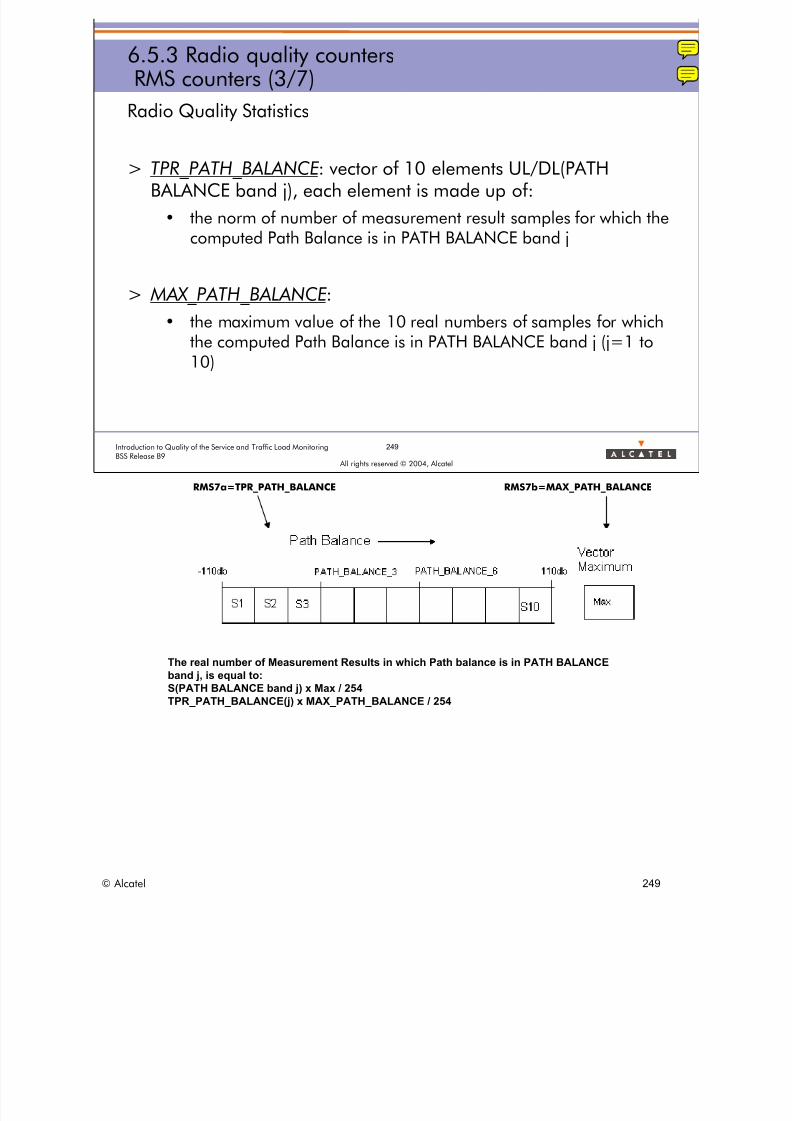
8/12/2019 QOS_B9 (Call Setup)
http://slidepdf.com/reader/full/qosb9-call-setup 249/388
249Introduction to Quality of the Service and Traffic Load MonitoringBSS Release B9
All rights reserved © 2004, Alcatel
6.5.3 Radio quality countersRMS counters (3/7)
Radio Quality Statistics
> TPR_PATH_BALANCE: vector of 10 elements UL/DL(PATHBALANCE band j), each element is made up of:
• the norm of number of measurement result samples for which thecomputed Path Balance is in PATH BALANCE band j
> MAX_PATH_BALANCE:
• the maximum value of the 10 real numbers of samples for whichthe computed Path Balance is in PATH BALANCE band j (j=1 to10)
RMS7a=TPR_PATH_BALANCE RMS7b=MAX_PATH_BALANCE
The real number of Measurement Results in which Path balance is in PATH BALANCE band j, is equal to: S(PATH BALANCE band j) x Max / 254
TPR_PATH_BALANCE(j) x MAX_PATH_BALANCE / 254
© Alcatel 249

8/12/2019 QOS_B9 (Call Setup)
http://slidepdf.com/reader/full/qosb9-call-setup 250/388
250Introduction to Quality of the Service and Traffic Load MonitoringBSS Release B9
All rights reserved © 2004, Alcatel
6.5.3 Radio quality countersRMS counters (4/7)
Radio Quality Statistics
> TPR_RADIO_LINK : vector of 10 elements UL(S band j), eachelement is made up of:
• the norm of number of measurement result samples for which theUplink Radio Link Counter is in S band j
> MAX_RADIO_LINK :
• the maximum value of the 10 real numbers of samples for whichthe Uplink Radio Link Counter is in S band j (j=1 to 10)
RMS6a=TPR_RADIO_LINK RMS6b=MAX_RADIO_LINK
The real number of Measurement Results in which Uplink Radio Link Counter is in S band j, is equal to: S(S band j) x Max / 254
TPR_RADIO_LINK(j) x MAX_RADIO_LINK / 254
© Alcatel 250
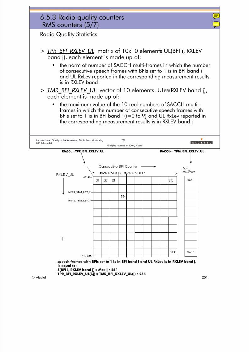
8/12/2019 QOS_B9 (Call Setup)
http://slidepdf.com/reader/full/qosb9-call-setup 251/388
The real number of Measurement Results in which the number of consecutive
251Introduction to Quality of the Service and Traffic Load MonitoringBSS Release B9
All rights reserved © 2004, Alcatel
6.5.3 Radio quality countersRMS counters (5/7)
Radio Quality Statistics
> TPR_BFI_RXLEV_UL: matrix of 10x10 elements UL(BFI i, RXLEVband j), each element is made up of:
• the norm of number of SACCH multi-frames in which the numberof consecutive speech frames with BFIs set to 1 is in BFI band iand UL RxLev reported in the corresponding measurement resultsis in RXLEV band j
> TMR_BFI_RXLEV_UL: vector of 10 elements ULBFI(RXLEV band j),each element is made up of:
• the maximum value of the 10 real numbers of SACCH multi-frames in which the number of consecutive speech frames withBFIs set to 1 is in BFI band i (i=0 to 9) and UL RxLev reported inthe corresponding measurement results is in RXLEV band j
RMS5a=TPR_BFI_RXLEV_UL RMS5b= TPM_BFI_RXLEV_UL
speech frames with BFIs set to 1 is in BFI band i and UL RxLev is in RXLEV band j,is equal to:S(BFI i, RXLEV band j) x Max j / 254TPR_BFI_RXLEV_UL(i,j) x TMR_BFI_RXLEV_UL(j) / 254
© Alcatel 251

8/12/2019 QOS_B9 (Call Setup)
http://slidepdf.com/reader/full/qosb9-call-setup 252/388
252Introduction to Quality of the Service and Traffic Load MonitoringBSS Release B9
All rights reserved © 2004, Alcatel
6.5.3 Radio quality countersRMS counters (6/7)
Radio Quality Statistics
> The BTS increments the BFI (or CFE) counter as soon asconsecutive speech frames cannot be decoded
• isolated speech frames with BFIs set to 1 are not counted
• sequences of not decoded speech frames are cumulated
SACCH mfr
CFE
0 0 0 0 0 0 0 0 1 2 3 3 3 3 4 4 4 5 6 6 6 6 6 7 7
BFI
Sf 1 Sf 2 Sf 3 Sf 4 Sf 5 Sf 6 Sf 7 Sf 8 Sf 9 Sf 10 Sf 11 Sf 12 Sf 13 Sf 14 Sf 15 Sf 16 Sf 17 Sf 18Sf 19 Sf 20 Sf 21 Sf 22 Sf 23 Sf 24 SACCH f.
0 0 0 1 0 0 0 1 1 1 1 0 0 1 1 0 1 1 1 0 1 0 1 1 0
RxLev UL
10 11 9 12 12 11 11 10 3 2 0 8 9 5 3 7 2 1 2 7 3 8 2 3 5
Av_RxLev_UL= - 110 + INT[(10+11+9+12+12+11+11+10+3+2+0+8+9+5+3+7+2+1+2+7+3+8+2+3+5)/25]
= -104 dBm
© Alcatel 252
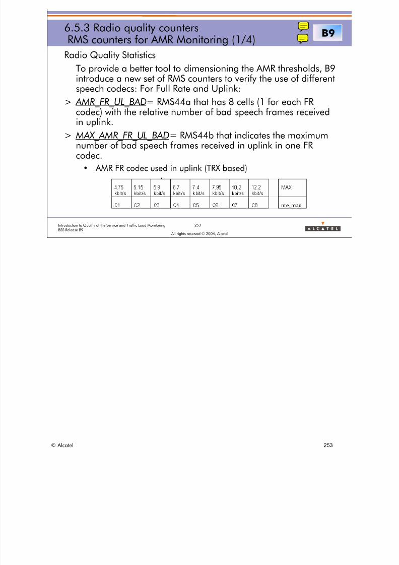
8/12/2019 QOS_B9 (Call Setup)
http://slidepdf.com/reader/full/qosb9-call-setup 253/388
253Introduction to Quality of the Service and Traffic Load MonitoringBSS Release B9
All rights reserved © 2004, Alcatel
6.5.3 Radio quality countersRMS counters for AMR Monitoring (1/4)
Radio Quality Statistics
To provide a better tool to dimensioning the AMR thresholds, B9
introduce a new set of RMS counters to verify the use of differentspeech codecs: For Full Rate and Uplink:
> AMR_FR_UL_BAD= RMS44a that has 8 cells (1 for each FRcodec) with the relative number of bad speech frames receivedin uplink.
> MAX_AMR_FR_UL_BAD= RMS44b that indicates the maximumnumber of bad speech frames received in uplink in one FRcodec.
• AMR FR codec used in uplink (TRX based)
B9
© Alcatel 253
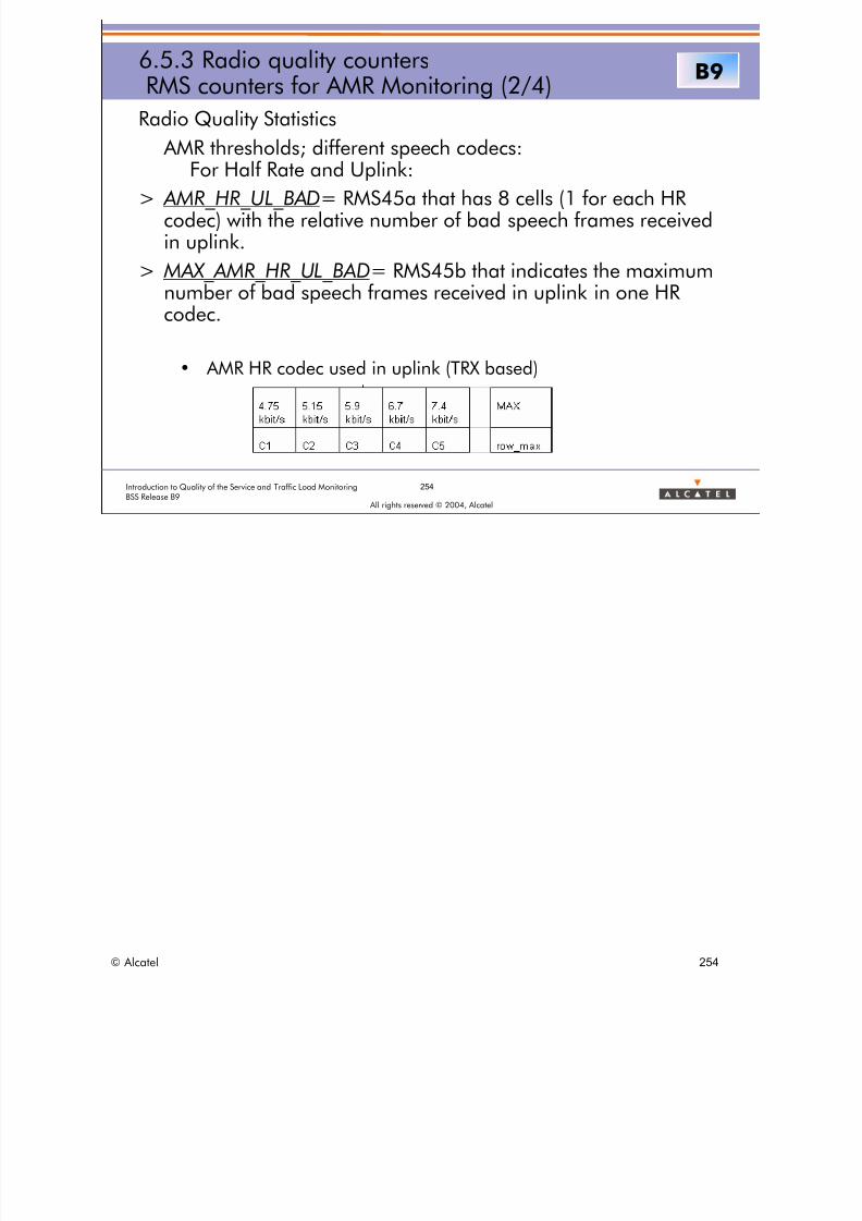
8/12/2019 QOS_B9 (Call Setup)
http://slidepdf.com/reader/full/qosb9-call-setup 254/388
254Introduction to Quality of the Service and Traffic Load MonitoringBSS Release B9
All rights reserved © 2004, Alcatel
6.5.3 Radio quality countersRMS counters for AMR Monitoring (2/4)
Radio Quality Statistics
AMR thresholds; different speech codecs:
For Half Rate and Uplink:> AMR_HR_UL_BAD= RMS45a that has 8 cells (1 for each HR
codec) with the relative number of bad speech frames receivedin uplink.
> MAX_AMR_HR_UL_BAD= RMS45b that indicates the maximumnumber of bad speech frames received in uplink in one HRcodec.
• AMR HR codec used in uplink (TRX based)
B9
© Alcatel 254
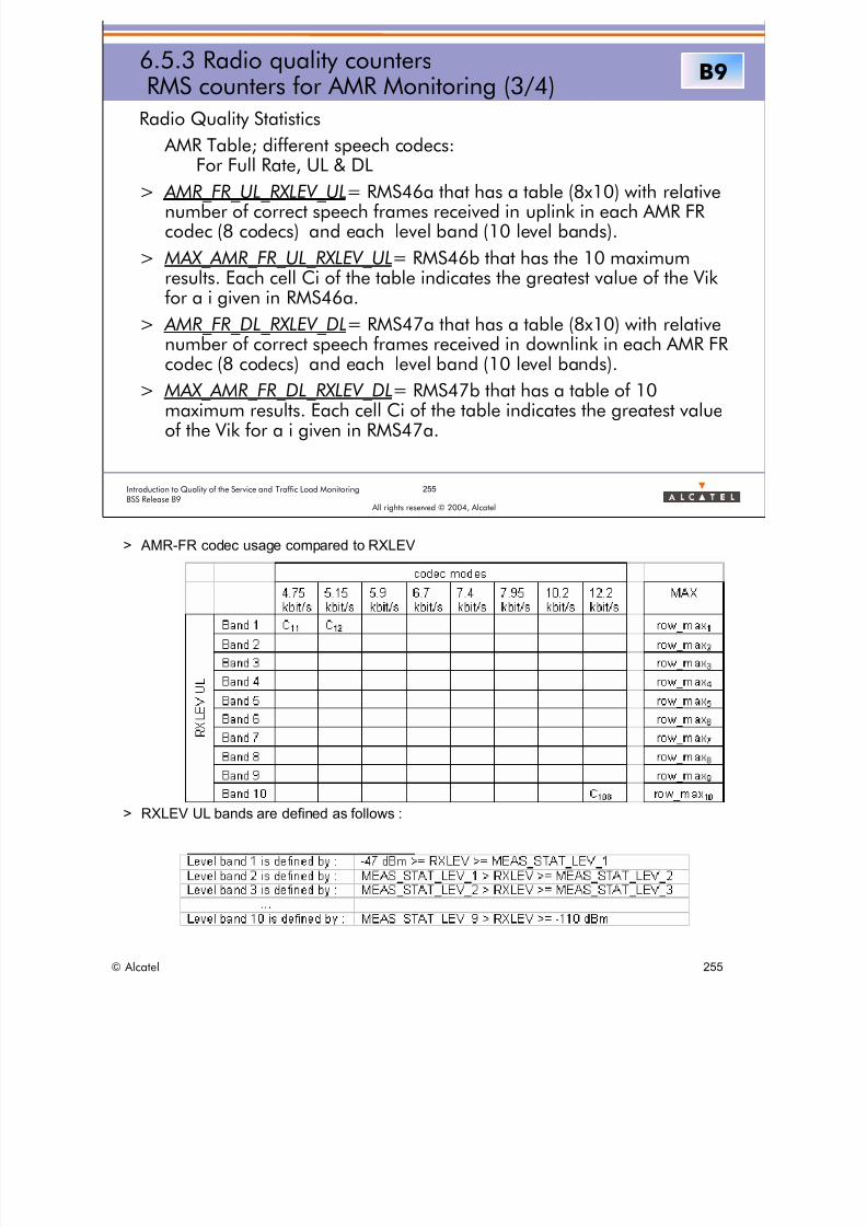
8/12/2019 QOS_B9 (Call Setup)
http://slidepdf.com/reader/full/qosb9-call-setup 255/388
255Introduction to Quality of the Service and Traffic Load MonitoringBSS Release B9
All rights reserved © 2004, Alcatel
6.5.3 Radio quality countersRMS counters for AMR Monitoring (3/4)
Radio Quality Statistics
AMR Table; different speech codecs:For Full Rate, UL & DL
> AMR_FR_UL_RXLEV_UL= RMS46a that has a table (8x10) with relativenumber of correct speech frames received in uplink in each AMR FRcodec (8 codecs) and each level band (10 level bands).
> MAX_AMR_FR_UL_RXLEV_UL= RMS46b that has the 10 maximumresults. Each cell Ci of the table indicates the greatest value of the Vikfor a i given in RMS46a.
> AMR_FR_DL_RXLEV_DL= RMS47a that has a table (8x10) with relative
number of correct speech frames received in downlink in each AMR FRcodec (8 codecs) and each level band (10 level bands).
> MAX_AMR_FR_DL_RXLEV_DL= RMS47b that has a table of 10maximum results. Each cell Ci of the table indicates the greatest valueof the Vik for a i given in RMS47a.
B9
> AMR-FR codec usage compared to RXLEV
> RXLEV UL bands are defined as follows :
© Alcatel 255

8/12/2019 QOS_B9 (Call Setup)
http://slidepdf.com/reader/full/qosb9-call-setup 256/388
256Introduction to Quality of the Service and Traffic Load MonitoringBSS Release B9
All rights reserved © 2004, Alcatel
6.5.3 Radio quality countersRMS counters for AMR Monitoring (4/4)
Radio Quality Statistics
AMR Table; different speech codecs:For Half Rate, UL & DL
> AMR_HR_UL_RXLEV_UL= RMS48a that has a table (5x10) with relativenumber of correct speech frames received in uplink in each AMR HRcodec (5 codecs) and each level band (10 level bands).
> MAX_AMR_HR_UL_RXLEV_UL= RMS48b that has a table of 10maximum results. Each cell Ci of the table indicates the greatest valueof the Vik for a i given in RMS48a.
> AMR_HR_DL_RXLEV_DL= RMS49a that has a table (5x10) with relative
number of correct speech frames received in downlink in each AMR HRcodec (5 codecs) and each level band (10 level bands).
> MAX_AMR_HR_DL_RXLEV_DL= RMS49b that has a table of 10maximum results. Each cell Ci of the table indicates the greatest valueof the Vik for a i given in RMS49a.
B9
> AMR-HR codec usage compared to RXLEV
> RXLEV UL bands are defined as follows :
© Alcatel 256

8/12/2019 QOS_B9 (Call Setup)
http://slidepdf.com/reader/full/qosb9-call-setup 257/388
257Introduction to Quality of the Service and Traffic Load MonitoringBSS Release B9
All rights reserved © 2004, Alcatel
6.5.3 Radio quality countersRMS counters for Timing Advance (1/3)
Radio Quality Statistics
> PERC_TA_GT_TA_STAT :
• percentage of measurement results reported with a Timing Advance value > TA_STAT parameter
> MAX_TA:
• maximum value of Timing Advance among all TA values reportedin the measurement results used for RMS
> Corresponding RMS counter numbers:
• RMS36 = PERC_TA_GT_TA_STAT
• RMS37 = MAX_TA
© Alcatel 257

8/12/2019 QOS_B9 (Call Setup)
http://slidepdf.com/reader/full/qosb9-call-setup 258/388
258Introduction to Quality of the Service and Traffic Load MonitoringBSS Release B9
All rights reserved © 2004, Alcatel
6.5.3 Radio quality countersRMS counters for Timing Advance (2/3)
> A new set of RMS counters related with timing advance analysis.TRX Based. (Rxlev for UL and DL)
• TPR_TIMING_ADVANCE= RMS50a that has 10 cells(1 for eachtiming advance band) with relative number of measurements ineach Timing advance band.
• MAX_TIMING_ADVANCE = RMS50b that has the greatest numberof measurements in one Timing advance band.
• TPR_UL_RXLEV_TA_BAND= RMS51 that has 10 cells (1 for eachtiming advance band) with average of uplink rxlev in
corresponding timing advance band.• TPR_DL_RXLEV_TA_BAND= RMS52 that has 10 cells (1 for each
timing advance band) with average of downlink rxlev incorresponding timing advance band.
B9
> The distribution of number of measurement reports for which the value of timing advance is inTA band X is described below:
> There are 10 TA bands which are defined through 9 thresholds parameters, tunable on a cell
basis, using the RMS_parameters_template :TA band 1 is defined by: 0 <= TA < Meas_STAT_TA_1
TA band 2 is defined by: MEAS_STAT_TA_1 <= TA < MEAS_STAT_TA_2
• … TA band 10 is defined by: MEAS_STAT_TA_9 <= TA < 63
> The TRE counts for each TA band the number of measurement results, N1 to N10. To save onthe memory resources, these counters are sent to the BSC in a coded format.
© Alcatel 258

8/12/2019 QOS_B9 (Call Setup)
http://slidepdf.com/reader/full/qosb9-call-setup 259/388
259Introduction to Quality of the Service and Traffic Load MonitoringBSS Release B9
All rights reserved © 2004, Alcatel
6.5.3 Radio quality countersRMS counters for Timing Advance (3/3)
> A new set of RMS counters related with timing advance analysis.
Uplink:
• TPR_UL_RXQUAL_TA_BAND= RMS53: Table of 10 resultsthat has 10 cells (1 for each timing advance band) with averageof uplink rxqual in corresponding timing advance band.
Downlink:
• TPR_DL_RXQUAL_TA_BAND= RMS54 Table of 10 resultsthat has 10 cells (1 for each timing advance band) with averageof uplink rxqual in corresponding timing advance band.
B9
> TPR_UL_RXQUAL_TA_BAND= RMS53
Table of 10 results; Each cell (i) of the table contains :
average value of UpLink Rxqual of reports in TA band i.
Averaged Rxqual is given with a precision of 2 digits after the comma (step size for coding =0.01, 0 coded 0, 0.01 coded 1, ...).
i = 1...10TA band i is defined by : MEAS_STAT_TA_ (i-1)<= Timing Advance < MEAS_STAT_TA_i
MEAS_STAT_TA_0 = 0 bper, MEAS_STAT_LEV_10 = 63 bper.
> TPR_DL_RXQUAL_TA_BAND= RMS54
Table of 10 results same for Downlink.
© Alcatel 259
8/12/2019 QOS_B9 (Call Setup)
http://slidepdf.com/reader/full/qosb9-call-setup 260/388
260Introduction to Quality of the Service and Traffic Load MonitoringBSS Release B9
All rights reserved © 2004, Alcatel
6.5.3 Radio quality countersRMS counters for Timing Advance (3/3)
> MAX_POWER_PER_TRX
Maximum GMSK TRX power level applied at the BTS antennaoutput connector in dBm.
• The power takes into account the different losses(cables, internal combiners)
• TRX Based
B9
> MAX_POWER_PER_TRX = RMSPw3
Maximum GMSK TRX power level applied at the BTS antenna output connector in dBm.
The power takes into account the different losses (cables, internal combiners) and theinternal/ external leveling but it does not take into account the BS-TXPWR-MAX,attenuation required by the OMC_R.
If the feature “unbalancing TRX output power per BTS sector" is activated (parameter “En-Unbalanced-Output-Power” set to 1), the counter is set by the BTS to the power requiredby the BSC for the corresponding TRE (i.e. for the TRE on which is mapped that TRX).
© Alcatel 260

8/12/2019 QOS_B9 (Call Setup)
http://slidepdf.com/reader/full/qosb9-call-setup 261/388
All rights reserved © 2004, Alcatel
6 RADIO MEASUREMENT STATISTICSINDICATORS
6.6 C/I statistics
© Alcatel 261

8/12/2019 QOS_B9 (Call Setup)
http://slidepdf.com/reader/full/qosb9-call-setup 262/388
All rights reserved © 2004, Alcatel
6 RADIO MEASUREMENT STATISTICSINDICATORS
6.6 C/I statistics
6.6.1 C/I Generalities
© Alcatel 262
8/12/2019 QOS_B9 (Call Setup)
http://slidepdf.com/reader/full/qosb9-call-setup 263/388
263Introduction to Quality of the Service and Traffic Load MonitoringBSS Release B9
All rights reserved © 2004, Alcatel
6.6.1 C/I GeneralitiesStorage and computation methods
> In order to provide an efficient storage, the "vector method"
already seen for previous RMS statistics will be used for C/Icounters
> C/I expressed in logarithmic scale (dB)
• (C/I)dB = CdBm - IdBm = 10 log10(CmW) - 10 log10(ImW)= 10 log10(C/I)mW
© Alcatel 263

8/12/2019 QOS_B9 (Call Setup)
http://slidepdf.com/reader/full/qosb9-call-setup 264/388
All rights reserved © 2004, Alcatel
6 RADIO MEASUREMENT STATISTICSINDICATORS
6.6 C/I statistics
6.6.2 C/I Parameters
© Alcatel 264

8/12/2019 QOS_B9 (Call Setup)
http://slidepdf.com/reader/full/qosb9-call-setup 265/388
265Introduction to Quality of the Service and Traffic Load MonitoringBSS Release B9
All rights reserved © 2004, Alcatel
6.6.2 C/I parametersRMS parameters
C/I statistics:parameters defining intervals for C/I statistics
> MEAS_STAT_C_I1 to MEAS_STAT_C_I9: 9 thresholds on theCarrier/Interference ratio defining 10 C/I bands
-63 < MEAS_STAT_C_I(i) ≤MEAS_STAT_C_I(i+1) ≤+63 dB
> EN_BALANCED_CI: boolean indicating if the C/I valuereported by the BTS is balanced or not
> NEIGB_CELL_ID: (BCCH,BSIC) of the neighboring cell forwhich the C/I statistics per neighboring cell are reported
> Frequency ARFCN: ARFCN of the frequency for which the C/Istatistics per MAFA frequency are reported
Annex 2
> All these parameters are included in the RMS PM Type 31 result files as RMS counters:
• RMSpt1 = TAB_PAR_MEAS_STAT_C/I = Table of 9 parameters MEAS_STAT_C_Ii
• RMSpa = PAR_EN_BALANCED_CI
• RMSp80 = NEIGB_CELL_ID
• RMSp90 = Frequency ARFCN
> For C/I statistics per neighboring cell:
• The C/I ratio is computed by the BTS from each Measurement Result message as the difference between:
– the downlink signal level measured by the MS on the serving TCH channel = C (dBm)
– the downlink signal level measured by the MS on the neighboring BCCH channel = I (dBm)• Two computation formulae may be used taking into account a corrective factor in case DL Power Control isused in the serving cell:
– If EN_BALANCED_CI = False
– then C/I (dB) = RXLEV_DL (dBm) - RXLEV_NCELL (dBm)
– else C/I (dB) = RXLEV_DL + abs(BS_TXPWR - BS_TXPWR_MAX) - RXLEV_NCELL
– The expression (RXLEV_DL + abs(BS_TXPWR - BS_TXPWR_MAX)) can be seen as a kind ofnormalized received power level in case the BTS would always have used the maximum allowedtransmit power level on the TCH channel.
> For C/I statistics per MAFA frequency:
• The C/I ratio is computed by the BTS from each Extended Measurement Report message in the same wayas the C/I ratio per neighboring cell.
© Alcatel 265
8/12/2019 QOS_B9 (Call Setup)
http://slidepdf.com/reader/full/qosb9-call-setup 266/388
All rights reserved © 2004, Alcatel
6 RADIO MEASUREMENT STATISTICSINDICATORS
6.6 C/I statistics6.6.3 C/I Counters
© Alcatel 266

8/12/2019 QOS_B9 (Call Setup)
http://slidepdf.com/reader/full/qosb9-call-setup 267/388
267Introduction to Quality of the Service and Traffic Load MonitoringBSS Release B9
All rights reserved © 2004, Alcatel
6.6.3 C/I countersRMS counters
C/I statistics per neighboring cell
> TPR_CIN: vector of 10 elements C/In(C/I band j), each elementis made up of:
• the norm of number of measurement result samples for which thecomputed Carrier/Interference ratio is in C/I band j
> MR_CIN:
• maximum value of the 10 real numbers of samples for which the
computed Carrier/Interference ratio is in C/I band j (j=1 to 10)
TPR_CIN and MR_CIN counters are provided for up to 42 neighboringcells
RMS8a=TPR_CIN RMS8b=TMR_CIN
For each reported neighboring cell (BCCH/BSIC): the Real number of Measurement Results for which the computed Carrier/Interference ratio is in C/I band j, is equal to: S(C/I band j) x Max / 254 TPR_CIN(j) x TMR_CIN / 254
For each declared/reported neighboring cell, the identification of this cell shall be done asfollows: BCCH_ARFCN and BSIC .The BCCH ARFCN is deduced in the BTS from the BCCH frequency index and the list ofindexed frequencies (sent by the BSC at the beginning of the RMS job).The RMS results report shall include all reported neighboring cells. Some of them correspondto known cells at the BSS level (i.e. their BSIC matches what is expected at the BSC side) butsome of them are unknown (their BSIC does not match). However, the BTS will handle the
same for both cases.The list of frequencies to be monitored by the mobile is limited to 33 but due to ‘resurgence’,the same frequency can be reported several times (each time with a different BSIC). If thenumber of reported cells is above the dimensioning limit (maximum 42 CI-vectors arereported), the extra new reported frequencies are not taken into account anymore. In theresult report, the related overflow indicator is set accordingly.
© Alcatel 267

8/12/2019 QOS_B9 (Call Setup)
http://slidepdf.com/reader/full/qosb9-call-setup 268/388
RMS9a TPR_CIF RMS9b TMR_CIF
268Introduction to Quality of the Service and Traffic Load MonitoringBSS Release B9
All rights reserved © 2004, Alcatel
6.6.3 C/I countersRMS counters
C/I statistics per MAFA frequency
> TPR_CIF: vector of 10 elements C/If(C/I band j), each element ismade up of:
• the norm of number of Extended Measurement Results samplesfor which the computed Carrier/Interference ratio is in C/I band j
> MR_CIF:
• maximum value of the 10 real numbers of samples for which the
computed Carrier/Interference ratio is in C/I band j (j=1 to 10)
TPR_CIF and MR_CIF counters are provided for up to 21 frequencies(serving cell BCCH + 20 MAFA frequencies)
= =
For each reported MAFA frequency (ARFCN):the Real number of Extended Measurement Results for which the computed
Carrier/Interference ratio is in C/I band j, is equal to:S(C/I band j) x Max / 254TPR_CIF(j) x TMR_CIF / 254
For each reported MAFA frequency, the identification of this frequency shall be done asfollows: Frequency ARFCN .
In case of a frequency reported via an Extended Measurement Reporting, no BSIC is required:the frequency ARFCN is not directly linked to a BCCH frequency. The ARFCN value of thefrequency is deduced in the BTS from the place of the measurement in the EXTENDED_MEASUREMENT_REPORT and from the ordered frequency list in the Extended MeasurementOrder. This list is built by the OMC-R and passed via BSC to BTS at the beginning of the RMSjob.
The maximum number of frequencies in the order (EMO) is the maximum defined in GSM(=21). Hence the maximum in the report is 21 also. When in exceptional cases, more resultsare available (future expansion in GSM), only the first 21 are reported.
© Alcatel The BCCH frequency of the serving cell shall always be part of the EMO-frequency list. 268

8/12/2019 QOS_B9 (Call Setup)
http://slidepdf.com/reader/full/qosb9-call-setup 269/388
All rights reserved © 2004, Alcatel
6 RADIO MEASUREMENT STATISTICSINDICATORS
6.7 RMS indicators usage
© Alcatel 269
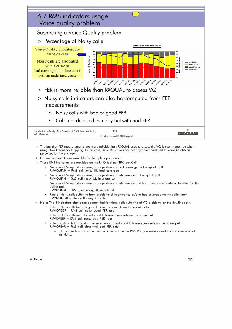
8/12/2019 QOS_B9 (Call Setup)
http://slidepdf.com/reader/full/qosb9-call-setup 270/388
270Introduction to Quality of the Service and Traffic Load MonitoringBSS Release B9
All rights reserved © 2004, Alcatel
6.7 RMS indicators usage Voice quality problem
Suspecting a Voice Quality problem
> Percentage of Noisy calls
> FER is more reliable than RXQUAL to assess VQ
> Noisy calls indicators can also be computed from FERmeasurements
• Noisy calls with bad or good FER
• Calls not detected as noisy but with bad FER
Voice Quality indicators are
based on calls
Noisy calls are associated
with a cause of
bad coverage, interference or
with an undefined cause
> The fact that FER measurements are more reliable than RXQUAL ones to assess the VQ is even more true whenusing Slow Frequency Hopping. In this case, RXQUAL values are not anymore correlated to Voice Quality asperceived by the end user.
> FER measurements are available for the uplink path only.
> These RMS indicators are provided on the RNO tool per TRX, per Cell:
• Number of Noisy calls suffering from problem of bad coverage on the uplink path RMVQULVN = RMS_call_noisy_UL_bad_coverage
• Number of Noisy calls suffering from problem of interference on the uplink path RMVQUIFN = RMS_call_noisy_UL_interference
• Number of Noisy calls suffering from problem of interference and bad coverage considered together on theuplink path
RMVQUUKN = RMS_call_noisy_UL_undefined
• Rate of Noisy calls suffering from problems of interference or/and bad coverage on the uplink pathRMVQUNOR = RMS_call_noisy_UL_rate
> Note: The 4 indicators above can be provided for Noisy calls suffering of VQ problems on the dowlink path.
• Rate of Noisy calls but with good FER measurements on the uplink path RMVQFEGR = RMS_call_noisy_good_FER_rate
• Rate of Noisy calls and also with bad FER measurements on the uplink path RMVQFEBR = RMS_call_noisy_bad_FER_rate
• Rate of calls with fair quality measurements but with bad FER measurements on the uplink pathRMVQFEAR = RMS_call_abnormal_bad_FER_rate
– This last indicator can be used in order to tune the RMS VQ parameters used to characterize a callas Noisy.
© Alcatel 270
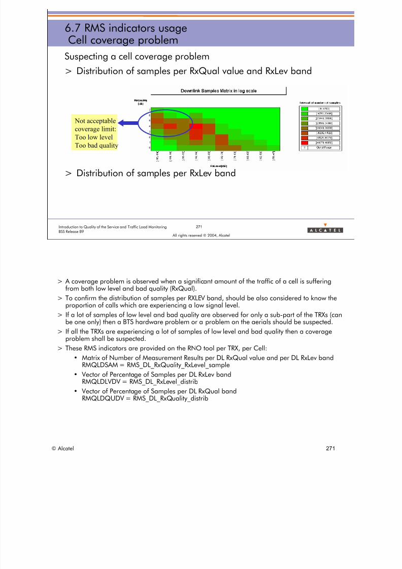
8/12/2019 QOS_B9 (Call Setup)
http://slidepdf.com/reader/full/qosb9-call-setup 271/388
271Introduction to Quality of the Service and Traffic Load MonitoringBSS Release B9
All rights reserved © 2004, Alcatel
Suspecting a cell coverage problem
> Distribution of samples per RxQual value and RxLev band
> Distribution of samples per RxLev band
6.7 RMS indicators usageCell coverage problem
Not acceptable
coverage limit:
Too low level
Too bad quality
> A coverage problem is observed when a significant amount of the traffic of a cell is sufferingfrom both low level and bad quality (RxQual).
> To confirm the distribution of samples per RXLEV band, should be also considered to know theproportion of calls which are experiencing a low signal level.
> If a lot of samples of low level and bad quality are observed for only a sub-part of the TRXs (canbe one only) then a BTS hardware problem or a problem on the aerials should be suspected.
> If all the TRXs are experiencing a lot of samples of low level and bad quality then a coverageproblem shall be suspected.
> These RMS indicators are provided on the RNO tool per TRX, per Cell:
• Matrix of Number of Measurement Results per DL RxQual value and per DL RxLev bandRMQLDSAM = RMS_DL_RxQuality_RxLevel_sample
• Vector of Percentage of Samples per DL RxLev band RMQLDLVDV = RMS_DL_RxLevel_distrib
• Vector of Percentage of Samples per DL RxQual band RMQLDQUDV = RMS_DL_RxQuality_distrib
© Alcatel 271

8/12/2019 QOS_B9 (Call Setup)
http://slidepdf.com/reader/full/qosb9-call-setup 272/388
272Introduction to Quality of the Service and Traffic Load MonitoringBSS Release B9
All rights reserved © 2004, Alcatel
6.7 RMS indicators usageCell coverage problem
Suspecting a cell coverage problem
> Average TA values per RxQual value and RxLev band
Not acceptable
coverage limit:
Too low level
Too bad quality
Acceptable coverage limit:
Sufficient level and good quality
% of TA value over TA
threshold has also to be
considered
> In order to know if the coverage problem is due to a big amount of traffic at the cell border orrather to indoor calls, the average TA value per RXQUAL value and RXLEV band as well as thePercentage of TA values over the TA threshold should be observed.
• Matrix of Average TA per UL RxQual value and per UL RxLev band RMQLUTAM = RMS_UL_RxQuality_RxLevel_TimingAdvance
• Rate of Measurements Results whose TA is greater than the TA threshold RMTAGTR = RMS_TimingAdvance_greater_threshold_rate
• Maximum TA value of all values reported in Measurement ResultsRMTAMXN = RMS_TimingAdvance_max
© Alcatel 272
8/12/2019 QOS_B9 (Call Setup)
http://slidepdf.com/reader/full/qosb9-call-setup 273/388
273Introduction to Quality of the Service and Traffic Load MonitoringBSS Release B9
All rights reserved © 2004, Alcatel
6.7 RMS indicators usageRMS Exercise 1
> Give the list of the RMS counters andparameters used in the 3 previous slides
Time allowed:
10 minutes
© Alcatel 273

8/12/2019 QOS_B9 (Call Setup)
http://slidepdf.com/reader/full/qosb9-call-setup 274/388
274Introduction to Quality of the Service and Traffic Load MonitoringBSS Release B9
All rights reserved © 2004, Alcatel
6.7 RMS indicators usageRMS exercise 2
> What does this graph represent?
> Interpret this graph
Time allowed:
10 minutes
© Alcatel 274

8/12/2019 QOS_B9 (Call Setup)
http://slidepdf.com/reader/full/qosb9-call-setup 275/388
275Introduction to Quality of the Service and Traffic Load MonitoringBSS Release B9
All rights reserved © 2004, Alcatel
6.7 RMS indicators usageCell interference problem
Suspecting a cell interference problem
> Number of samples per RxQual value and RxLev band
Average DL RxQuality = 0.34
RMS results show no problemof radio link quality in this cell
Average RxQual value per
RxLev band has also to be
considered
> These RMS indicators are provided on the RNO tool per TRX, per Cell:
• Matrix of Number of Measurement Results per DL RxQual value and per DL RxLev bandRMQLDSAM = RMS_DL_RxQuality_RxLevel_sample
• Vector of Average DL RxQual per RxLev band RMQLDQUAV = RMS_DL_RxQuality_avg_per_RxLevel
• Average DL RxQuality
RMQLDQUAN = RMS_DL_RxQuality_avg
© Alcatel 275

8/12/2019 QOS_B9 (Call Setup)
http://slidepdf.com/reader/full/qosb9-call-setup 276/388
276Introduction to Quality of the Service and Traffic Load MonitoringBSS Release B9
All rights reserved © 2004, Alcatel
6.7 RMS indicators usageRMS exercise 3
Average RxQual value per
RxLev band has also to be
considered
Average DL RxQuality =
2.81
> Interpret this graph
© Alcatel 276

8/12/2019 QOS_B9 (Call Setup)
http://slidepdf.com/reader/full/qosb9-call-setup 277/388
277Introduction to Quality of the Service and Traffic Load MonitoringBSS Release B9
All rights reserved © 2004, Alcatel
6.7 RMS indicators usageRMS exercise 4
Time allowed:
15 minutes
© Alcatel 277
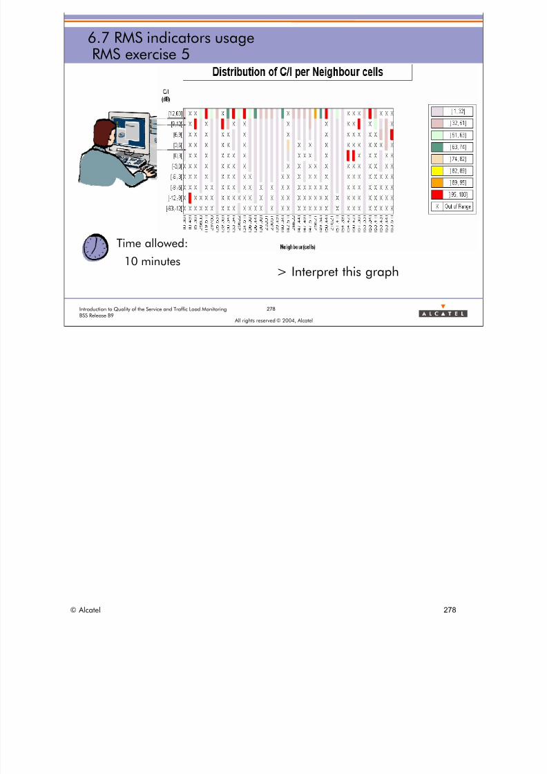
8/12/2019 QOS_B9 (Call Setup)
http://slidepdf.com/reader/full/qosb9-call-setup 278/388
278Introduction to Quality of the Service and Traffic Load MonitoringBSS Release B9
All rights reserved © 2004, Alcatel
6.7 RMS indicators usageRMS exercise 5
> Interpret this graph
Time allowed:
10 minutes
© Alcatel 278

8/12/2019 QOS_B9 (Call Setup)
http://slidepdf.com/reader/full/qosb9-call-setup 279/388
279Introduction to Quality of the Service and Traffic Load MonitoringBSS Release B9
All rights reserved © 2004, Alcatel
6.7 RMS indicators usageRMS exercise 6
– Compute the RMS counters and indicators inthe file
Time allowed:
10 minutes
© Alcatel 279
8/12/2019 QOS_B9 (Call Setup)
http://slidepdf.com/reader/full/qosb9-call-setup 280/388
All rights reserved © 2004, Alcatel
6 RADIO MEASUREMENT STATISTICSINDICATORS
6.8 Additional information
© Alcatel 280

8/12/2019 QOS_B9 (Call Setup)
http://slidepdf.com/reader/full/qosb9-call-setup 281/388
281Introduction to Quality of the Service and Traffic Load MonitoringBSS Release B9
All rights reserved © 2004, Alcatel
6.8 Additional informationRMS counters (1/3)
Counters used for:
> post-processing the RMS results provided per TRX
• TOT_SEIZ_TCH: number of TCH channels successfully seized by the MS
• TOT_MEAS: number of Measurement Results used for RMS
• TOT_MEAS_L1INFO_NOL3INFO: number of Measurement Results usedfor RMS statistics for which Layer 1 info is present but Layer 3 is missing
• TOT_MEAS_DTX_UL: number of Measurement Results used for RMSstatistics for which DTX UL was used in the corresponding SACCH mfr
• TOT_MEAS_DTX_DL: number of Measurement Results used for RMS
statistics for which DTX DL was used in the corresponding SACCH mfr• TOT_EMR: number of Extended Measurement Results used for RMS
statistics
> Corresponding RMS counter numbers:
• RMS31 = TOT_SEIZ_TCH
• RMS32 = TOT_MEAS
• RMS33 = TOT_MEAS_L1INFO_NOL3INFO
• RMS34 = TOT_MEAS_DTX_UL
• RMS35 = TOT_MEAS_DTX_DL
• RMS38 = TOT_EMR
> Note:
• If during an SACCH measurement, DTX is applied on the uplink path (DTX_UL =1), thecounters on consecutive BFIs (RMS5a, RMS5b) shall not be incremented and thecorresponding measurement result shall not be taken into account in these RMS counters.
• If during an SACCH measurement, DTX is applied on the uplink path (DTX_UL = 1), theFER measurement does not take place.
© Alcatel 281

8/12/2019 QOS_B9 (Call Setup)
http://slidepdf.com/reader/full/qosb9-call-setup 282/388
282Introduction to Quality of the Service and Traffic Load MonitoringBSS Release B9
All rights reserved © 2004, Alcatel
6.8 Additional informationRMS counters (2/3)
Counters used for:
> interpreting the RMS results provided per TRX
• TRE_BAND: frequency band of the TRX• BS_TX_PWRMAX: effective maximum output power of the BTS on
any channel of the TRX as an offset from the maximum absoluteoutput power (in dB)
• MS_TX_PWRMAX: effective maximum output power of the MSusing any channel of the TRX (in dBm)
• IND_TRE_OVERLOAD: boolean indicating if the TRE handling theTRX function has experienced a data loss due to a processor
overload during the RMS campaign• IND_RMS_RESTARTED: boolean indicating if the RMS job has
been restarted on the concerned TRE during the RMS campaigndue to a modification of the RMS parameter values or a TRE reset
> Corresponding RMS counter numbers: RMS20 = TRE_BAND
• RMSpw1 = BS_TX_PWRMAX
• RMSpw2 = MS_TX_PWRMAX
• RMS21 = IND_TRE_OVERLOAD
• RMS22 = IND_RMS_RESTARTED
© Alcatel 282
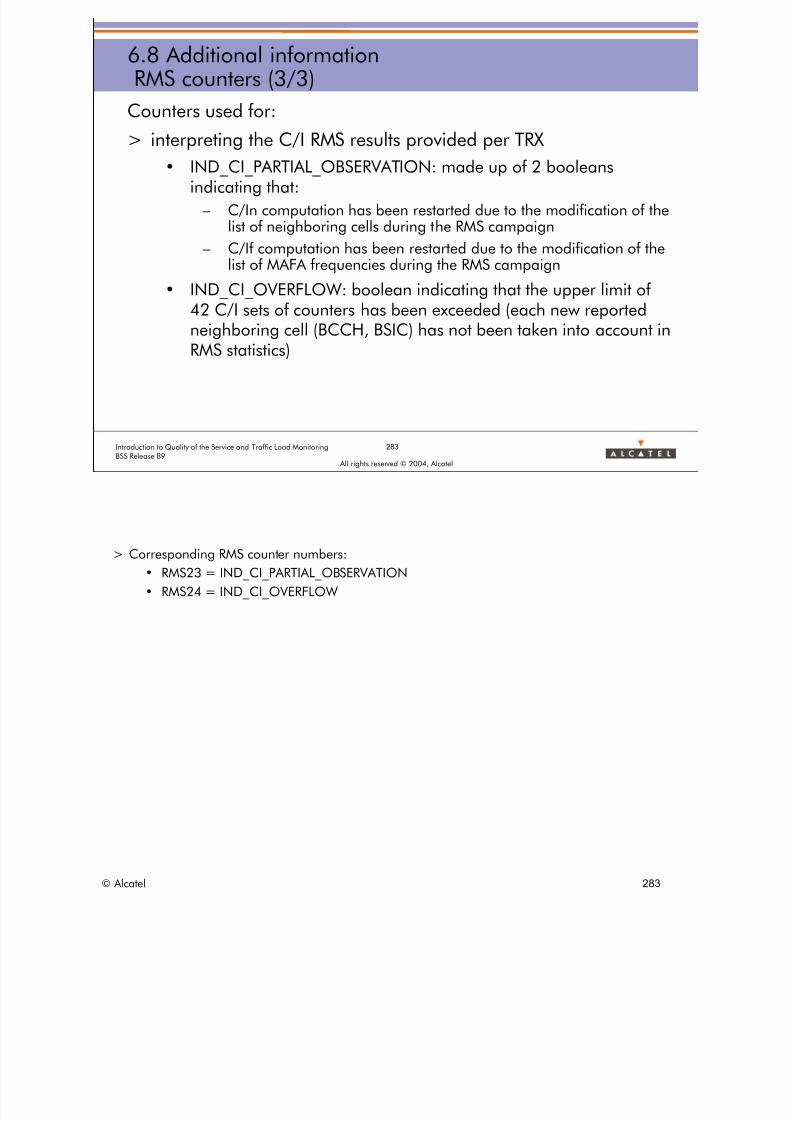
8/12/2019 QOS_B9 (Call Setup)
http://slidepdf.com/reader/full/qosb9-call-setup 283/388
283Introduction to Quality of the Service and Traffic Load MonitoringBSS Release B9
All rights reserved © 2004, Alcatel
6.8 Additional informationRMS counters (3/3)
Counters used for:
> interpreting the C/I RMS results provided per TRX
• IND_CI_PARTIAL_OBSERVATION: made up of 2 booleansindicating that:
– C/In computation has been restarted due to the modification of thelist of neighboring cells during the RMS campaign
– C/If computation has been restarted due to the modification of thelist of MAFA frequencies during the RMS campaign
• IND_CI_OVERFLOW: boolean indicating that the upper limit of42 C/I sets of counters has been exceeded (each new reportedneighboring cell (BCCH, BSIC) has not been taken into account inRMS statistics)
> Corresponding RMS counter numbers:
• RMS23 = IND_CI_PARTIAL_OBSERVATION
• RMS24 = IND_CI_OVERFLOW
© Alcatel 283

8/12/2019 QOS_B9 (Call Setup)
http://slidepdf.com/reader/full/qosb9-call-setup 284/388
All rights reserved © 2004, Alcatel
7 TRAFFIC INDICATORS
© Alcatel 284

8/12/2019 QOS_B9 (Call Setup)
http://slidepdf.com/reader/full/qosb9-call-setup 285/388
285Introduction to Quality of the Service and Traffic Load MonitoringBSS Release B9
All rights reserved © 2004, Alcatel
7 Traffic indicatorsSection presentation
> Objective: to be able to describe BSS traffic indicators used for
radio resource dimensioning
> Program:
• 7.1 Call mix definition
• 7.2 Basis of traffic theory
• 7.3 TCH resource allocation indicators
• 7.4 Resource occupancy indicators
• 7.5 Traffic model indicators
• 7.6 Preemption indicators
© Alcatel 285

8/12/2019 QOS_B9 (Call Setup)
http://slidepdf.com/reader/full/qosb9-call-setup 286/388
All rights reserved © 2004, Alcatel
7 TRAFFIC INDICATORS
7.1 Call mix definition
© Alcatel 286

8/12/2019 QOS_B9 (Call Setup)
http://slidepdf.com/reader/full/qosb9-call-setup 287/388
287Introduction to Quality of the Service and Traffic Load MonitoringBSS Release B9
All rights reserved © 2004, Alcatel
7.1 Call mix definitionGSM transactions
> In a GSM Network, there are a lot of different transactions :
• location update: periodic, new updating, ~imsi_attach,~imsi_detach
• Hand Over (intra-cell, internal, external, etc.)
• SMS (Short Message Service, originating or terminating)
• SS (Supplementary Service) (I.e: number presentation)
• Paging
• and also Originating and Terminating calls, etc.• and so on (data, SMS-CB, etc.)
> In a GSM network, telecom procedures involve different kinds of resource in the BSS:
• Location Update: RACH, AGCH, SDCCH and SCCP
• Originated Call: RACH, AGCH, SDCCH, TCH and SCCP
• Terminated Call: PCH, RACH, AGCH, SDCCH, TCH and SCCP
• Handover: TCH, SCCP
• etc.
© Alcatel 287

8/12/2019 QOS_B9 (Call Setup)
http://slidepdf.com/reader/full/qosb9-call-setup 288/388
7.1 Call mix definitionGSM transactions
> One can quantify the number of each transaction per hour
> For example, for one cell, one can measure:
• 900 calls (600 TCs, 300 OCs)
• 3600 LUs (any type)
• 1350 HOs (900 internal, 450 external)
• 100 SMSs
• 5 SSs
• 6000 pagings
• With the following characteristics
• mean call duration on TCH: 50 seconds
• mean SDCCH duration: 3.2 seconds
288Introduction to Quality of the Service and Traffic Load MonitoringBSS Release B9
All rights reserved © 2004, Alcatel
> A Call mix can be defined through:
• data given by the Marketing team.
• data measured from the living network.
> Before network design, a Call Mix is assessed from Marketing Studies or observations fromother networks.
> After commercial opening, a Call Mix is measured from the real traffic.
> Caution: Call duration means here TCH duration. The duration of a call from call setup to callrelease is an NSS notion.
© Alcatel 288
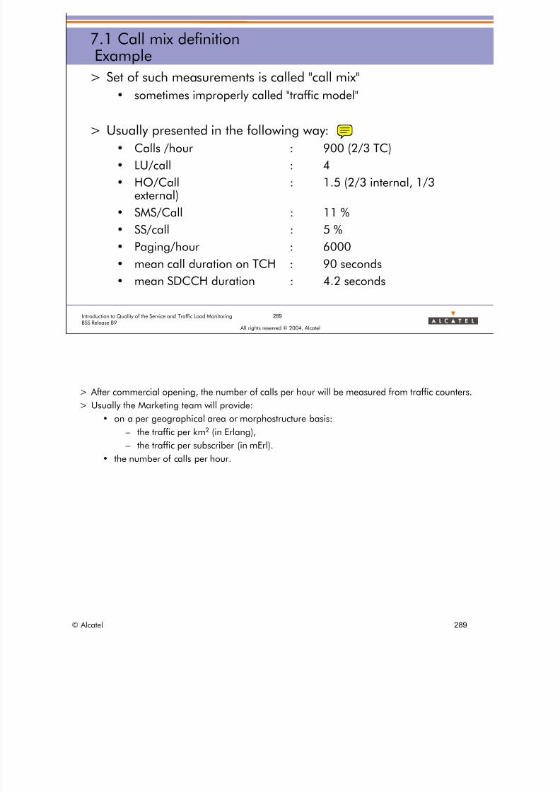
8/12/2019 QOS_B9 (Call Setup)
http://slidepdf.com/reader/full/qosb9-call-setup 289/388
7.1 Call mix definitionExample
> Set of such measurements is called "call mix"
• sometimes improperly called "traffic model"
> Usually presented in the following way:
• Calls /hour : 900 (2/3 TC)
• LU/call : 4
• HO/Call : 1.5 (2/3 internal, 1/3external)
• SMS/Call : 11 %
• SS/call : 5 %• Paging/hour : 6000
• mean call duration on TCH : 90 seconds
• mean SDCCH duration : 4.2 seconds
289Introduction to Quality of the Service and Traffic Load MonitoringBSS Release B9
All rights reserved © 2004, Alcatel
> After commercial opening, the number of calls per hour will be measured from traffic counters.
> Usually the Marketing team will provide:
• on a per geographical area or morphostructure basis:
– the traffic per km2 (in Erlang),
– the traffic per subscriber (in mErl).
• the number of calls per hour.
© Alcatel 289

8/12/2019 QOS_B9 (Call Setup)
http://slidepdf.com/reader/full/qosb9-call-setup 290/388
290Introduction to Quality of the Service and Traffic Load MonitoringBSS Release B9
All rights reserved © 2004, Alcatel
7.1 Call mix definition Variation
> A call mix is varying a lot:
• from a cell to another
– TCH traffic (induced by subscribers)
– number of LU/call and HO/call (induced by network design)
• from one hour to another
– by default: busy hour
• from one year to another
– modification of traffic intensity and distribution
> On some university campus, an SMS/call is often higher than the average.
© Alcatel 290

8/12/2019 QOS_B9 (Call Setup)
http://slidepdf.com/reader/full/qosb9-call-setup 291/388
291Introduction to Quality of the Service and Traffic Load MonitoringBSS Release B9
All rights reserved © 2004, Alcatel
7.1 Call mix definitionUsage
> Interests of call mix: Input data for dimensioning
• Cell and BSC resources dimensioning
– RTCH, SDCCH, TTCH, BTS, BSC and MSC CPU processor
• Some examples of "risky" call mix
– too many LU/Calls: SDCCH congestion, TCU load, MSC overload
– too many HO/calls: speech quality, call drop, DTC load
– too many calls: TCH congestion
– too many paging: DTC processor load, PCH congestion
> A Call Mix will be used at Radio Network Design and Radio Network Planning stages in order todefine the capacity of the network (number of sites, TRXs per site, radio configuration, numberof Abis-PCM, A-PCM).
> When the network is in operation, a Call Mix is used in order to anticipate network extension orre-dimensioning.
© Alcatel 291
8/12/2019 QOS_B9 (Call Setup)
http://slidepdf.com/reader/full/qosb9-call-setup 292/388
292Introduction to Quality of the Service and Traffic Load MonitoringBSS Release B9
All rights reserved © 2004, Alcatel
7.1 Call mix definition Advises
> Some advises
• LU/CALL: 1 is "good", 2 is "bad", 4 and more can be dangerous
– beware of the Network or BSC averages which can hide criticalcells
• HO/Call: less critical (1 is good)
– 2 or 3 is not a direct problem, but the trend has to be monitored
• Call: to be checked with an Erlang table (seen in next session)
© Alcatel 292

8/12/2019 QOS_B9 (Call Setup)
http://slidepdf.com/reader/full/qosb9-call-setup 293/388
293Introduction to Quality of the Service and Traffic Load MonitoringBSS Release B9
All rights reserved © 2004, Alcatel
7.1 Call mix definitionExercise
> Compute the call mix of a cell according
the following information• 256 call/hour
• 1300 LU/hour
• 450 HO/hour
> Is it complete?
> What are the risks of such a call mix?
Time allowed:
15 minutes
© Alcatel 293

8/12/2019 QOS_B9 (Call Setup)
http://slidepdf.com/reader/full/qosb9-call-setup 294/388
All rights reserved © 2004, Alcatel
7 TRAFFIC INDICATORS
7.2 Basis of traffic theory
© Alcatel 294

8/12/2019 QOS_B9 (Call Setup)
http://slidepdf.com/reader/full/qosb9-call-setup 295/388
295Introduction to Quality of the Service and Traffic Load MonitoringBSS Release B9
All rights reserved © 2004, Alcatel
7.2 Basis of traffic theoryErlang definition
> ERLANG: unit used to quantify traffic (intensity)
T = (resource usage duration) / (total observation duration)[ERLANG]
> Example:
• For 1 TCH, observed during 1 hour
• one can observe 2 calls: 1 of 80 seconds and 1 of 100 seconds
T = (80+100)/3600 = 0.05 ERLANG
© Alcatel 295

8/12/2019 QOS_B9 (Call Setup)
http://slidepdf.com/reader/full/qosb9-call-setup 296/388
7.2 Basis of traffic theoryErlang from call mix
CALL MIX => ERLANG
> Call mix example:
• 350 call/hour
• 3 LU/call
• TCH mean call duration: 85 seconds
• SDCCH mean duration: 4.5 seconds
• Computation of Carried ErlangTCH = (350*85)/3600: 8.26 ERLANGS
SDCCH = [ (350+350*3) * 4.5 ] / 3600 = 1.75 Erlang
296Introduction to Quality of the Service and Traffic Load MonitoringBSS Release B9
All rights reserved © 2004, Alcatel
© Alcatel 296

8/12/2019 QOS_B9 (Call Setup)
http://slidepdf.com/reader/full/qosb9-call-setup 297/388
297Introduction to Quality of the Service and Traffic Load MonitoringBSS Release B9
All rights reserved © 2004, Alcatel
7.2 Basis of traffic theoryErlang B law
> In a Telecom system, the call arrival frequency is ruled by the
POISSON law> Erlang B law: relationship between:
• offered traffic
• number of resources
• blocking rate
© Alcatel 297

8/12/2019 QOS_B9 (Call Setup)
http://slidepdf.com/reader/full/qosb9-call-setup 298/388
298Introduction to Quality of the Service and Traffic Load MonitoringBSS Release B9
All rights reserved © 2004, Alcatel
7.2 Basis of traffic theoryErlang B law
> The call request arrival rate (and leaving) is not stable
number of resources = average number of requests * mean duration
is sometimes not sufficient => probability of blocking
=> Erlang B law
• Pblock: blocking probability
• N: number of resources
• E: offered traffic [Erlang]
> Good approximation when the blocking rateis low (< 5 %)
Telecom system
OfferedCarried
Rejected
Pblo ck N
k
N
k
k
N
E
E=
=∑
!
!0
> The Erlang B law is not fully accurate since it assumes that:
• the subscriber requests are not queued which is not always the case (TCH queued in theBSC),
• the subscriber does not repeat his call request if rejected, which is almost never the case.
> Therefore the higher the blocking rate the worse is the approximation of the Erlang B law.
> The Erlang C law modelizes better the TCH resource usage of the BSS since it takes into accountthe queuing.
> However the Erlang C law is never used since parameters like size of the queue and time spentinto the queue have to be tuned.
© Alcatel 298

8/12/2019 QOS_B9 (Call Setup)
http://slidepdf.com/reader/full/qosb9-call-setup 299/388
299Introduction to Quality of the Service and Traffic Load MonitoringBSS Release B9
All rights reserved © 2004, Alcatel
7.2 Basis of traffic theoryErlang B formulae
> There are two different ways to use this law
• Using Abacus
• Using SW (here Excel)
– Pblock = f (T, Nc)
– Offered = f (Nc, Pblock)
– Channels = f (T, Pblock)
© Alcatel 299

8/12/2019 QOS_B9 (Call Setup)
http://slidepdf.com/reader/full/qosb9-call-setup 300/388
300Introduction to Quality of the Service and Traffic Load MonitoringBSS Release B9
All rights reserved © 2004, Alcatel
7.2 Basis of traffic theoryErlang B abacus
© Alcatel 300

8/12/2019 QOS_B9 (Call Setup)
http://slidepdf.com/reader/full/qosb9-call-setup 301/388
301Introduction to Quality of the Service and Traffic Load MonitoringBSS Release B9
All rights reserved © 2004, Alcatel
7.2 Basis of traffic theoryErlang B example
> Example:
1 cell with 8 TRXs, with 60 TCH channels
Maximum blocking rate: 2 %
• Erlang law: 50 Offered Erlang
• 83 % of TCH resources used to reach 2% of blocking
© Alcatel 301

8/12/2019 QOS_B9 (Call Setup)
http://slidepdf.com/reader/full/qosb9-call-setup 302/388
302Introduction to Quality of the Service and Traffic Load MonitoringBSS Release B9
All rights reserved © 2004, Alcatel
7.2 Basis of traffic theoryNon linearity of Erlang B
> But be careful, the Erlang B law is not linear:
• If we use for example a combined BCCH with a micro BTS.
– 4 SDCCHs, Pblock = 2% => T = 1.1 E
– 25% resources used to reach 2% blocking
• if we decide to provide SMSCB (Cell Broadcast information),1 SDCCH stolen for CBCH
– 3 SDCCH, Pblock = 2% => T = 0.6 E
– 25 % resources less => 50 % Traffic less!!
© Alcatel 302

8/12/2019 QOS_B9 (Call Setup)
http://slidepdf.com/reader/full/qosb9-call-setup 303/388
303Introduction to Quality of the Service and Traffic Load MonitoringBSS Release B9
All rights reserved © 2004, Alcatel
7.2 Basis of traffic theoryCell dimensioning
> Given an Offered traffic, compute the number of TRXs (and
SDCCH) needed to carry it => What is the accepted blockingrate?
> default blocking rate
• RTCH: 2 %
• SDCCH: 0.5 %
• (for BSC TTCH: 0.1%)
> The Erlang B law is less relevant for SDCCH dimensioning since SDCCH traffic cannot bemodelized like TCH traffic. Indeed SDCCH is not only due to subscriber traffic but also toLocation Update, SMS, IMSI Detach, etc.
> For SDCCH dimensioning, some typical configurations are used according to the number ofTRXs in the cell, the LA plan.
© Alcatel 303
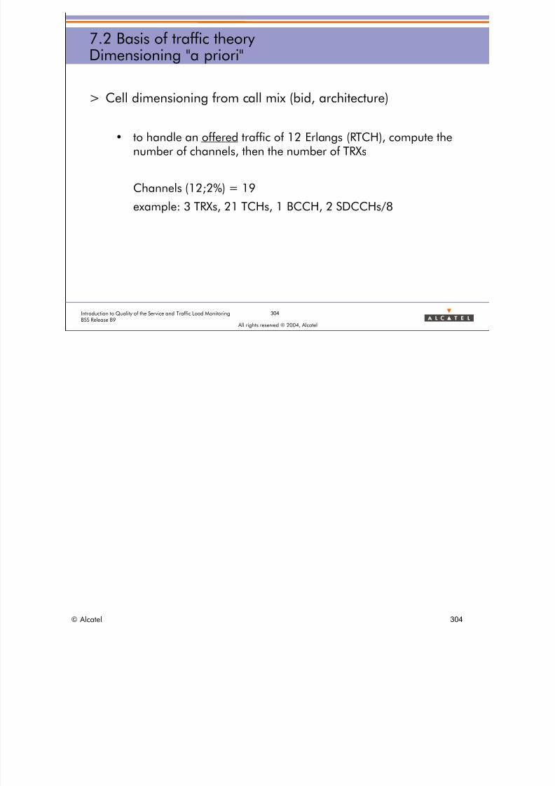
8/12/2019 QOS_B9 (Call Setup)
http://slidepdf.com/reader/full/qosb9-call-setup 304/388
304Introduction to Quality of the Service and Traffic Load MonitoringBSS Release B9
All rights reserved © 2004, Alcatel
7.2 Basis of traffic theoryDimensioning "a priori"
> Cell dimensioning from call mix (bid, architecture)
• to handle an offered traffic of 12 Erlangs (RTCH), compute thenumber of channels, then the number of TRXs
Channels (12;2%) = 19
example: 3 TRXs, 21 TCHs, 1 BCCH, 2 SDCCHs/8
© Alcatel 304
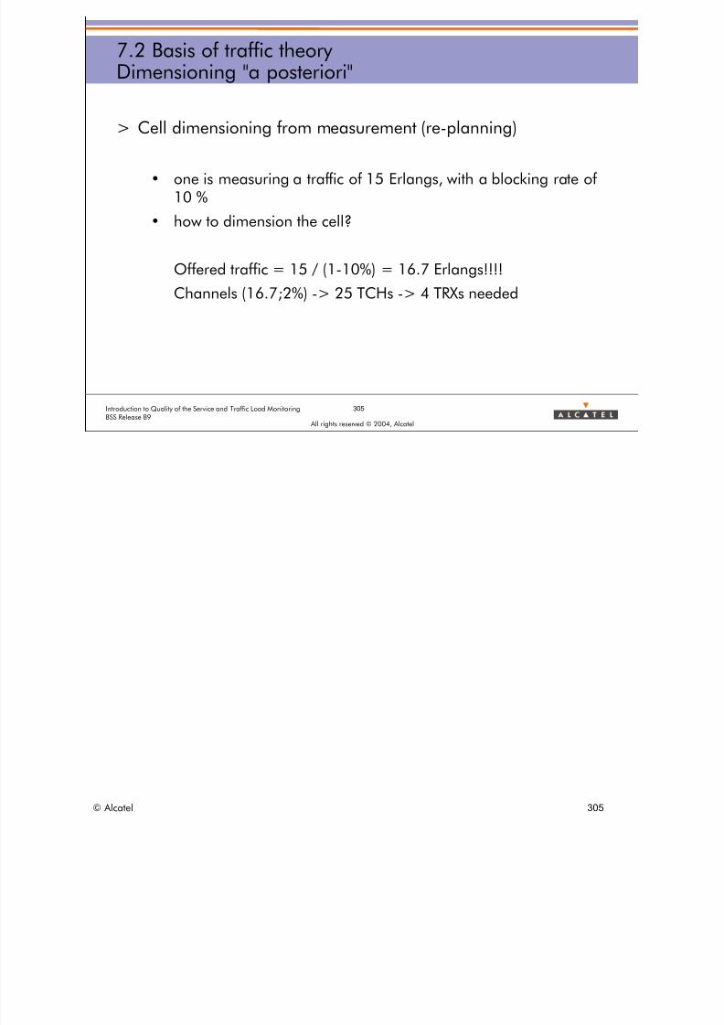
8/12/2019 QOS_B9 (Call Setup)
http://slidepdf.com/reader/full/qosb9-call-setup 305/388
305Introduction to Quality of the Service and Traffic Load MonitoringBSS Release B9
All rights reserved © 2004, Alcatel
7.2 Basis of traffic theoryDimensioning "a posteriori"
> Cell dimensioning from measurement (re-planning)
• one is measuring a traffic of 15 Erlangs, with a blocking rate of10 %
• how to dimension the cell?
Offered traffic = 15 / (1-10%) = 16.7 Erlangs!!!!
Channels (16.7;2%) -> 25 TCHs -> 4 TRXs needed
© Alcatel 305

8/12/2019 QOS_B9 (Call Setup)
http://slidepdf.com/reader/full/qosb9-call-setup 306/388
306Introduction to Quality of the Service and Traffic Load MonitoringBSS Release B9
All rights reserved © 2004, Alcatel
7.2 Basis of traffic theoryForecast / Critical traffic
> Forecast traffic
• traffic forecasting must be computed according to the offeredtraffic
– not directly on the measured traffic
• In order to plan the necessary actions soon enough, one mustcompute regularly the date when the traffic of a cell will becomecritical
> Critical traffic
• critical traffic: when the offered traffic will induce 2% of blocking
• traffic capacity of a cell = critical traffic of this cell
© Alcatel 306

8/12/2019 QOS_B9 (Call Setup)
http://slidepdf.com/reader/full/qosb9-call-setup 307/388
307Introduction to Quality of the Service and Traffic Load MonitoringBSS Release B9
All rights reserved © 2004, Alcatel
7.2 Basis of traffic theoryExercise
Training exercise: complete the form to get less than 2% of blocking
cell call mix info Erlang TCHOffered traffic
traffic forecast proposed config
12, 743 450 call/hourmean TCH call duration : 80secblocking rate TCH : 0.8%
10,08 Erlang TCH 30 % offered trafficincrease
13,1 Erlang TCH - > 20 TCH3 TRX
12,675 330 call/hourmean TCH call duration 129sec
blocking rate 4%
30 % offered trafficincrease
12,865 600 call/hourmean TCH call duration 96secblocking rate 8 %
30 % offered trafficincrease
© Alcatel 307

8/12/2019 QOS_B9 (Call Setup)
http://slidepdf.com/reader/full/qosb9-call-setup 308/388
All rights reserved © 2004, Alcatel
7 TRAFFIC INDICATORS
7.3 TCH resource allocation indicators
© Alcatel 308

8/12/2019 QOS_B9 (Call Setup)
http://slidepdf.com/reader/full/qosb9-call-setup 309/388
309Introduction to Quality of the Service and Traffic Load MonitoringBSS Release B9
All rights reserved © 2004, Alcatel
7.3 TCH resource allocation indicatorsRadio Allocation and Management
> Radio resource allocation and management (RAM) aims at:
• Managing pools of TCH radio resources by:
– defining TCH radio timeslots as a function of the cell radioconfiguration from the operator
– sorting these TCH TS according to their radio capabilities (FR or DR,frequency band (G1 or GSM/DCS))
• Allocating dedicated TCH radio resources by:
– selecting the TCH pool in which the TCH should be chosenaccording to:
– the requested channel rate (FR or HR)
– the radio capability of the mobile– the TRE DR capability and the TRE band
– selecting the best TCH resource among the available TCH channelsof this pool according to several criteria
© Alcatel 309
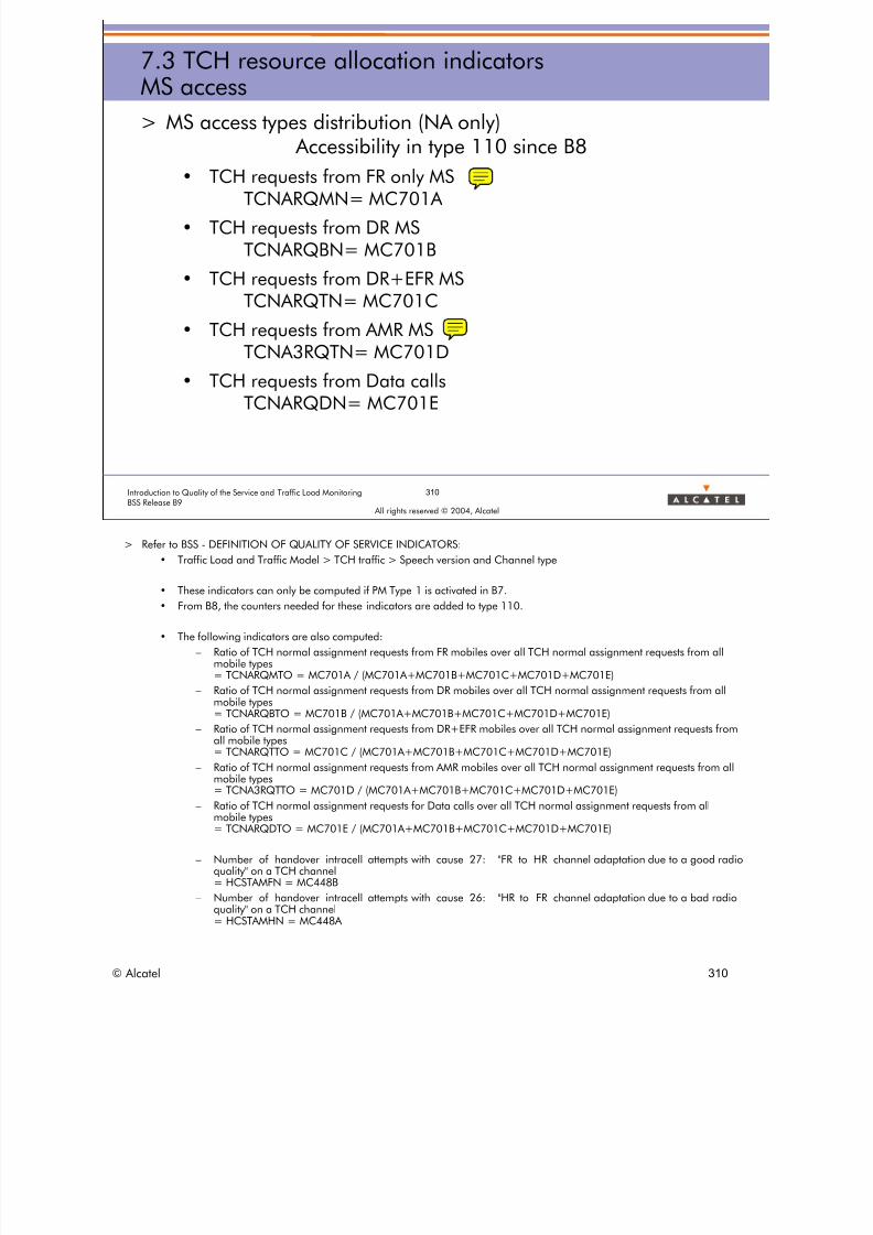
8/12/2019 QOS_B9 (Call Setup)
http://slidepdf.com/reader/full/qosb9-call-setup 310/388
310Introduction to Quality of the Service and Traffic Load MonitoringBSS Release B9
All rights reserved © 2004, Alcatel
7.3 TCH resource allocation indicatorsMS access
> MS access types distribution (NA only) Accessibility in type 110 since B8
• TCH requests from FR only MSTCNARQMN= MC701A
• TCH requests from DR MSTCNARQBN= MC701B
• TCH requests from DR+EFR MSTCNARQTN= MC701C
• TCH requests from AMR MS
TCNA3RQTN= MC701D• TCH requests from Data calls
TCNARQDN= MC701E
> Refer to BSS - DEFINITION OF QUALITY OF SERVICE INDICATORS:
• Traffic Load and Traffic Model > TCH traffic > Speech version and Channel type
• These indicators can only be computed if PM Type 1 is activated in B7.
• From B8, the counters needed for these indicators are added to type 110.
• The following indicators are also computed:
– Ratio of TCH normal assignment requests from FR mobiles over all TCH normal assignment requests from allmobile types= TCNARQMTO = MC701A / (MC701A+MC701B+MC701C+MC701D+MC701E)
– Ratio of TCH normal assignment requests from DR mobiles over all TCH normal assignment requests from allmobile types= TCNARQBTO = MC701B / (MC701A+MC701B+MC701C+MC701D+MC701E)
– Ratio of TCH normal assignment requests from DR+EFR mobiles over all TCH normal assignment requests fromall mobile types= TCNARQTTO = MC701C / (MC701A+MC701B+MC701C+MC701D+MC701E)
– Ratio of TCH normal assignment requests from AMR mobiles over all TCH normal assignment requests from allmobile types= TCNA3RQTTO = MC701D / (MC701A+MC701B+MC701C+MC701D+MC701E)
– Ratio of TCH normal assignment requests for Data calls over all TCH normal assignment requests from allmobile types= TCNARQDTO = MC701E / (MC701A+MC701B+MC701C+MC701D+MC701E)
– Number of handover intracell attempts with cause 27: "FR to HR channel adaptation due to a good radioquality" on a TCH channel
= HCSTAMFN = MC448B– Number of handover intracell attempts with cause 26: "HR to FR channel adaptation due to a bad radio
quality" on a TCH channel= HCSTAMHN = MC448A
© Alcatel 310

8/12/2019 QOS_B9 (Call Setup)
http://slidepdf.com/reader/full/qosb9-call-setup 311/388
311Introduction to Quality of the Service and Traffic Load MonitoringBSS Release B9
All rights reserved © 2004, Alcatel
7.3 TCH resource allocation indicatorsSpeech coding version
> Speech coding Version capabilities distribution (NA only) Accessibility in type 110 since B8
• TCH allocations with FR SV1TCNACAFN= MC702A
• TCH allocations with HR SV1TCNACAHN= MC702B
• TCH allocations with FR SV2 (EFR)TCNACAEN= MC702C
• TCH allocations with FR SV3 (AMR FR)
TCNA3CAFN= MC704A• TCH allocations with HR SV3 (AMR HR)
TCNA3CAHN= MC704B
• TCH allocations for data callTCNACADN= MC705
> Refer to BSS - DEFINITION OF QUALITY OF SERVICE INDICATORS:
• Traffic Load and Traffic Model > TCH traffic > Speech version and Channel type
• These indicators can only be computed if PM Type 1 is activated in B7.
• From B8, the counters needed for these Indicators are added to type 110.
• The following indicators are also computed:
– Ratio of TCH allocations with FR SV1 over all TCH allocations during normal assignment= TCNACAFTO = MC702A / (MC702A+MC702B+MC702C+MC704A+MC704B+MC705)
– Ratio of TCH allocations with HR SV1 over all TCH allocations during normal assignment= TCNACAHTO = MC702B / (MC702A+MC702B+MC702C+MC704A+MC704B+MC705)
– Ratio of TCH allocations with EFR over all TCH allocations during normal assignment= TCNACAETO = MC702C / (MC702A+MC702B+MC702C+MC704A+MC704B+MC705)
– Ratio of TCH allocations with AMR FR over all TCH allocations during normal assignment= TCNA3CAFTO = MC704A / (MC702A+MC702B+MC702C+MC704A+MC704B+MC705)
– Ratio of TCH allocations with AMR HR over all TCH allocations during normal assignment= TCNA3CAHTO = MC704A / (MC702A+MC702B+MC702C+MC704A+MC704B+MC705)
– Ratio of TCH allocations for Data calls over all TCH allocations during normal assignment= TCNACADTO = MC705 / (MC702A+MC702B+MC702C+MC704A+MC704B+MC705)
– Rate of successful TCH allocations with AMR SV over all AMR MS requests= TCNA3SUR = (MC704A+MC704B) / MC701D
© Alcatel 311

8/12/2019 QOS_B9 (Call Setup)
http://slidepdf.com/reader/full/qosb9-call-setup 312/388
312Introduction to Quality of the Service and Traffic Load MonitoringBSS Release B9
All rights reserved © 2004, Alcatel
7.3 TCH resource allocation indicatorsDistributions
> FR/HR calls distribution (NA+HO)
• FR TCH allocation ratio
TCAHCAFO = MC370A / (MC370A+MC370B)• HR TCH allocation ratio
TCAHCAHO = MC370B / (MC370A+MC370B)
> NA/HO distribution
• Normal Assignment TCH allocation ratioTCNACAO = MC703 / (MC703 + [MC15A+MC15B])
• Handover TCH allocation ratioTCHOCAO = [MC15A+MC15B] / (MC703 +
[MC15A+MC15B])> TCH allocation distribution per TRX
• Number of TCH allocations for Normal AssignmentTCNACAN = MC703
> Refer to BSS - DEFINITION OF QUALITY OF SERVICE INDICATORS:
• Traffic Load and Traffic Model > TCH traffic > Resource occupancy
– MC370A = Number of FR TCH allocations (FR+EFR+AMR FR)
– MC370B = Number of HR TCH allocations (HR+AMR HR)
– MC703 = Number of TCH allocations for Normal Assignment.
– MC15A = Number of TCH allocations for Internal Directed Retry.
–
MC15B = Number of TCH allocations for Handover (intra cell, internal, external).
– TCNACAN indicator is also available as the MAX value of the day on the A9156RNO tool.
• Some of these indicators are also available for SDCCH:
– SDCCH allocation distribution per TRX through the number of SDCCH allocations
– SDAHCAN = MC390
– SDCCH Assignment/HO distribution through the ratio of SDCCH allocations for Assignment
– SDNACAO = MC148 / MC390
© Alcatel 312

8/12/2019 QOS_B9 (Call Setup)
http://slidepdf.com/reader/full/qosb9-call-setup 313/388
All rights reserved © 2004, Alcatel
7 TRAFFIC INDICATORS
7.4 Resource occupancy indicators
© Alcatel 313

8/12/2019 QOS_B9 (Call Setup)
http://slidepdf.com/reader/full/qosb9-call-setup 314/388
314Introduction to Quality of the Service and Traffic Load MonitoringBSS Release B9
All rights reserved © 2004, Alcatel
7.4 Resource occupancy indicatorsTCH resource
> TCH resource occupancy
• TCH traffic in Erlang
TCTRE= (MC380A+MC380B) / 3600• TCH mean holding time (TCH average duration)
TCTRMHT= (MC380A+MC380B) / (MC370A+MC370B)
• FR TCH traffic in ErlangTCTRE= MC380A / 3600
• FR TCH mean holding timeTCTRFMHT= MC380A/ MC370A
• HR TCH traffic in ErlangTCTRE= MC380B / 3600
• HR TCH mean holding timeTCTRHMHT= MC380B/ MC370B
> Refer to BSS - DEFINITION OF QUALITY OF SERVICE INDICATORS:
• Traffic Load and Traffic Model > TCH traffic > Resource occupancy
– MC380A = Cumulated FR TCH duration per TRX
– MC380B = Cumulated HR TCH duration per TRX
• The following indicators can also be computed:
– TCTRME = Multiband MS TCH traffic in Erlang = MC381 / 3600
– TCTRSE = Single band MS TCH traffic in Erlang = ([MC380A+MC380B] - MC381) / 3600
– MC381 = Cumulated (FR+HR) TCH duration of Multiband mobiles per TRX
A split of counters (MC380a and MC380b) is added, in B8, to make the distinction between traffic in differentfrequency bands: here after the corresponding stored indicators (type 110):
– TCTRFTTGT = Time (in seconds) during which the TCH radio timeslot or dynamic SDCCH/8 timeslot in theGSM frequency band is busy in FR usage = MC380C
– TCTRHTTGT = Time (in seconds) during which the TCH radio timeslot or dynamic SDCCH/8 timeslot in theGSM frequency band is busy in HR usage = MC380D
– TCTRFTTDT = Time (in seconds) during which the TCH radio timeslot or dynamic SDCCH/8 timeslot in theDCS/PCS frequency band is busy in FR usage = MC380E
–
TCTRHTTDT = Time (in seconds) during which the TCH radio timeslot or dynamic SDCCH/8 timeslot in theDCS/PCS frequency band is busy in HR usage = MC380F
© Alcatel 314

8/12/2019 QOS_B9 (Call Setup)
http://slidepdf.com/reader/full/qosb9-call-setup 315/388
315Introduction to Quality of the Service and Traffic Load MonitoringBSS Release B9
All rights reserved © 2004, Alcatel
7.4 Resource occupancy indicatorsSDCCH / ACH resource
> SDCCH resource occupancy
• SDCCH traffic in Erlang
SDTRE= MC400 / 3600• SDCCH mean holding time (SDCCH average duration)
SDTRMHT= MC400 / MC390
> ACH resource occupancy
• ACH traffic in ErlangC750 / 3600
• ACH mean holding time (ACH average duration)QSTRN =C750 / C751
> Refer to BSS - DEFINITION OF QUALITY OF SERVICE INDICATORS:
• Traffic Load and Traffic Model > SDCCH traffic > Resource occupancy
– MC400 = Cumulated SDCCH duration per TRX
– MC380 = Number of SDCCH allocations per TRX
> C750 and C751 are 2 counters introduced from B7 in type 18. Both are provided per TTCH (Achannel):
• C750 = TIME_A_CHANNEL_BUSY: Time (in seconds) during which the A channel is busy(allocated).
• C751 = NB_A_CHANNEL_ALLOC: Number of allocations of the A channel.
© Alcatel 315

8/12/2019 QOS_B9 (Call Setup)
http://slidepdf.com/reader/full/qosb9-call-setup 316/388
All rights reserved © 2004, Alcatel
7 TRAFFIC INDICATORS
7.5 Traffic model indicators
© Alcatel 316

8/12/2019 QOS_B9 (Call Setup)
http://slidepdf.com/reader/full/qosb9-call-setup 317/388
317Introduction to Quality of the Service and Traffic Load MonitoringBSS Release B9
All rights reserved © 2004, Alcatel
7.5 Traffic model indicatorsSDCCH establishment
> SDCCH establishment cause distribution
• Ratio of MT calls
TMMTO= MC01 / SDCCH ASSIGN SUCCESS• Ratio of MO normal and emergency calls
TMMTO= MC02H / SDCCH ASSIGN SUCCESS
• Ratio of LU normal (resp. follow-on)TMMOLUR = MC02A (resp. MC02D) / SDCCH ASSIGN SUCCESS
• Ratio of IMSI detachTMMOLUDR= MC02G / SDCCH ASSIGN SUCCESS
• Ratio of Short Message Service
TMMOSMSR= MC02B / SDCCH ASSIGN SUCCESS• Ratio of Supplementary Service
TMMOSSR= MC02C / SDCCH ASSIGN SUCCESS
• Ratio of Call re-establishmentTMMOCRR= MC02E / SDCCH ASSIGN SUCCESS
> Refer to BSS - DEFINITION OF QUALITY OF SERVICE INDICATORS:
• Traffic Load and Traffic Model > SDCCH traffic > Traffic model
• SDCCH ASSIGN SUCCESS = Total number of SDCCH establishments for network access= MC01 + MC02
• These indicators allow to get call mix data from the network.
© Alcatel 317
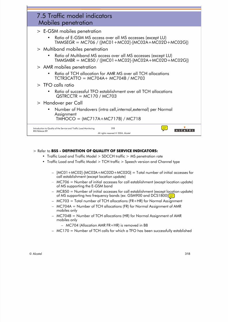
8/12/2019 QOS_B9 (Call Setup)
http://slidepdf.com/reader/full/qosb9-call-setup 318/388
318Introduction to Quality of the Service and Traffic Load MonitoringBSS Release B9
All rights reserved © 2004, Alcatel
7.5 Traffic model indicatorsMobiles penetration
> E-GSM mobiles penetration
• Ratio of E-GSM MS access over all MS accesses (except LU)TMMSEGR = MC706 / ([MC01+MC02]-[MC02A+MC02D+MC02G])
> Multiband mobiles penetration
• Ratio of Multiband MS access over all MS accesses (except LU)TMMSMBR = MC850 / ([MC01+MC02]-[MC02A+MC02D+MC02G])
> AMR mobiles penetration
• Ratio of TCH allocation for AMR MS over all TCH allocationsTCTR3CATTO = MC704A+ MC704B / MC703
> TFO calls ratio
• Ratio of successful TFO establishment over all TCH allocationsQSTRCCTR = MC170 / MC703
> Handover per Call
• Number of Handovers (intra cell,internal,external) per Normal AssignmentTMHOCO = (MC717A+MC717B) / MC718
> Refer to BSS - DEFINITION OF QUALITY OF SERVICE INDICATORS:
• Traffic Load and Traffic Model > SDCCH traffic > MS penetration rate
• Traffic Load and Traffic Model > TCH traffic > Speech version and Channel type
– [MC01+MC02]-[MC02A+MC02D+MC02G] = Total number of initial accesses forcall establishment (except location update)
– MC706 = Number of initial accesses for call establishment (except location update)
of MS supporting the E-GSM band– MC850 = Number of initial accesses for call establishment (except location update)
of MS supporting two frequency bands (ex: GSM900 and DCS1800)
– MC703 = Total number of TCH allocations (FR+HR) for Normal Assignment
– MC704A = Number of TCH allocations (FR) for Normal Assignment of AMRmobiles only
– MC704B = Number of TCH allocations (HR) for Normal Assignment of AMRmobiles only
– MC704 (Allocation AMR FR+HR) is removed in B8
– MC170 = Number of TCH calls for which a TFO has been successfully established
© Alcatel 318

8/12/2019 QOS_B9 (Call Setup)
http://slidepdf.com/reader/full/qosb9-call-setup 319/388
All rights reserved © 2004, Alcatel
7 TRAFFIC INDICATORS
7.6 Preemption indicators
© Alcatel 319
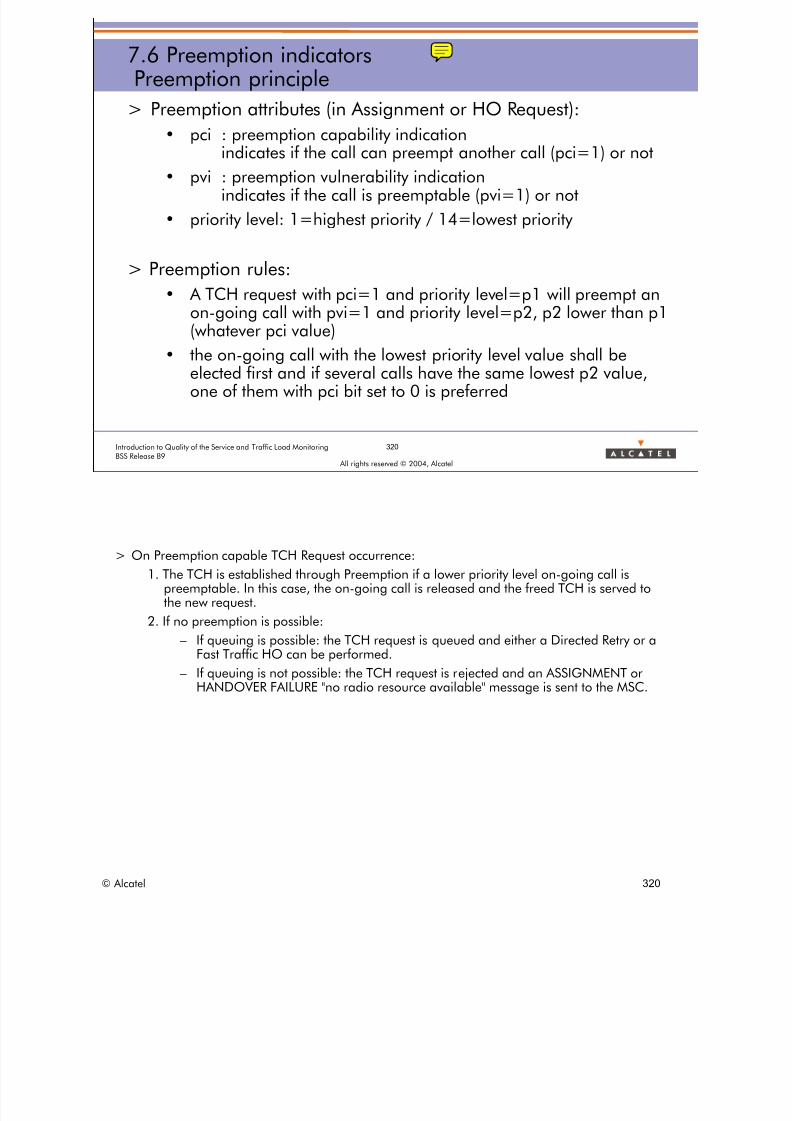
8/12/2019 QOS_B9 (Call Setup)
http://slidepdf.com/reader/full/qosb9-call-setup 320/388
320Introduction to Quality of the Service and Traffic Load MonitoringBSS Release B9
All rights reserved © 2004, Alcatel
7.6 Preemption indicatorsPreemption principle
> Preemption attributes (in Assignment or HO Request):
• pci : preemption capability indication
indicates if the call can preempt another call (pci=1) or not• pvi : preemption vulnerability indication
indicates if the call is preemptable (pvi=1) or not
• priority level: 1=highest priority / 14=lowest priority
> Preemption rules:
• A TCH request with pci=1 and priority level=p1 will preempt anon-going call with pvi=1 and priority level=p2, p2 lower than p1(whatever pci value)
• the on-going call with the lowest priority level value shall beelected first and if several calls have the same lowest p2 value,one of them with pci bit set to 0 is preferred
> On Preemption capable TCH Request occurrence:
1. The TCH is established through Preemption if a lower priority level on-going call ispreemptable. In this case, the on-going call is released and the freed TCH is served tothe new request.
2. If no preemption is possible:
–
If queuing is possible: the TCH request is queued and either a Directed Retry or aFast Traffic HO can be performed.
– If queuing is not possible: the TCH request is rejected and an ASSIGNMENT orHANDOVER FAILURE "no radio resource available" message is sent to the MSC.
© Alcatel 320

8/12/2019 QOS_B9 (Call Setup)
http://slidepdf.com/reader/full/qosb9-call-setup 321/388
321Introduction to Quality of the Service and Traffic Load MonitoringBSS Release B9
All rights reserved © 2004, Alcatel
7.6 Preemption indicatorsPreemption counters
> MC921A = Number of TCH Requests with the capability topreempt another call with lower priority (pci=1)
> MC921B = Number of preemption capable TCH Requests(pci=1) served with TCH resource (with or without using thepreemption feature).
> MC921C = Number of preempted calls
> MC921D = Number of preemption capable TCH Request(pci=1) successfully served in a neighboring cell with the help ofthe directed retry procedure
> MC921E = Number of preemptable calls successfullyestablished (pvi=1)
> Refer to BSS - DEFINITION OF QUALITY OF SERVICE INDICATORS:
• GLOBAL Quality of service INDICATORS> RTCH > Preemption feature
© Alcatel 321

8/12/2019 QOS_B9 (Call Setup)
http://slidepdf.com/reader/full/qosb9-call-setup 322/388
322Introduction to Quality of the Service and Traffic Load MonitoringBSS Release B9
All rights reserved © 2004, Alcatel
7.6 Preemption indicators
> Preemption capable TCH Request rejection rate
• TCPPFLCR = (MC921A-MC921B-MC921D) / MC921A
> Ratio of preemption capable TCH Request which led to asuccessful Directed Retry
• TCPPDSUCR = MC921D / MC921A
> Ratio of preemptable calls established over all calls
• TCPPSUVO = MC921E / (MC718+MC717A+MC717B)
> Refer to BSS - DEFINITION OF QUALITY OF SERVICE INDICATORS
• GLOBAL Quality of service INDICATORS> RTCH > Preemption feature
© Alcatel 322
8/12/2019 QOS_B9 (Call Setup)
http://slidepdf.com/reader/full/qosb9-call-setup 323/388
323Introduction to Quality of the Service and Traffic Load MonitoringBSS Release B9
All rights reserved © 2004, Alcatel
Introduction to QoS and Traffic Load monitoring / B9Evaluation
> Objective: to be able to interpret:
– Global indicators, in order to assess the general qualityof the network
– Detailed indicators, in order to detect / identify / locatethe main malfunctions
– Handover indicators, in order to quantify the efficiencyand the reason for HO
– Directed retry indicators, in order to quantify theefficiency of a directed retry
– Indicators provided by the new RMS feature to easeradio optimization and fault detection
– Traffic indicators, in order to detect/predict overloadand compute adequate cell dimensioning as well as tounderstand how RTCH resources are used in thenetwork
Thank you foransweringthe objectives sheet
© Alcatel 323
8/12/2019 QOS_B9 (Call Setup)
http://slidepdf.com/reader/full/qosb9-call-setup 324/388
All rights reserved © 2004, Alcatel
CASE STUDIES
© Alcatel 324

8/12/2019 QOS_B9 (Call Setup)
http://slidepdf.com/reader/full/qosb9-call-setup 325/388
CASE STUDIESSection presentation
> Objective: to be able to analyse with the KPI QOS some typical
problems.> Program:
• 1 Congestion
• 2 Sector problem
• 3 QSCSSR
• 4 Quality
• 5 RMS Level / Hardware problem• 6 Interference
• 7 BSS Problem
325Introduction to Quality of the Service and Traffic Load MonitoringBSS Release B9
All rights reserved © 2004, Alcatel
© Alcatel 325

8/12/2019 QOS_B9 (Call Setup)
http://slidepdf.com/reader/full/qosb9-call-setup 326/388
All rights reserved © 2004, Alcatel
CASE STUDIES 1
CASE STUDIES 1
Congestion
© Alcatel 326

8/12/2019 QOS_B9 (Call Setup)
http://slidepdf.com/reader/full/qosb9-call-setup 327/388
327Introduction to Quality of the Service and Traffic Load MonitoringBSS Release B9
All rights reserved © 2004, Alcatel
CASE STUDIES 1
> From this RNO table: What is the worst SDCCH congested cell?
> Choose 2 other interesting indicators to continue your analysis?– Call Drop %
– SDCCH Assignment Failure %– Outgoing Handover Success %
– SDCCH Drop %
– Downlink TBF drop %
– RTCH assign fail %
© Alcatel 327

8/12/2019 QOS_B9 (Call Setup)
http://slidepdf.com/reader/full/qosb9-call-setup 328/388
All rights reserved © 2004, Alcatel
CASE STUDIES 2
CASE STUDIES 2
Sector problem
© Alcatel 328

8/12/2019 QOS_B9 (Call Setup)
http://slidepdf.com/reader/full/qosb9-call-setup 329/388
329Introduction to Quality of the Service and Traffic Load MonitoringBSS Release B9
All rights reserved © 2004, Alcatel
CASE STUDIES 2
> In this trisectorised site,
give the worst sector?
> What can you proposeto do?
© Alcatel 329

8/12/2019 QOS_B9 (Call Setup)
http://slidepdf.com/reader/full/qosb9-call-setup 330/388
All rights reserved © 2004, Alcatel
CASE STUDIES 3
CASE STUDIES 3
QSCSSR
© Alcatel 330

8/12/2019 QOS_B9 (Call Setup)
http://slidepdf.com/reader/full/qosb9-call-setup 331/388
CASE STUDIES 3
> Write the formula using the reference name (MCx) and computethe CSSR for this 2 cells:
( 1 - SDCCH_drop_%) * ( 1 - RTCH_assign_unsuccess_% ) With:
SDCCH_drop_% = SDCCH_drop / SDCCH_assign_success
RTCH_ass_Un_%= RTCH_assign_unsuccess / RTCH_assign_request
Counter Definition Paris_Tower_S1 Paris_City_S3MC138 SDCCH drops on SDCCH established phase due to Radio Link Fail. 9 4
MC07 SDCCH drops during any outgoing SDCCH handover 0 0
MC137 SDCCH drops in SDCCH established phase due to BSS problem 1 2
MC01 SDCCH assign success for Mobile Terminating procedure 43 924
MC02 SDCCH assign success for Mobile Originating procedure 663 1352
MC140a normal assignment requests for TCH establishment (HR or FR) 88 1455
MC718 TCH normal assignment successes (HR or FR) 84 1430
QSCSSR=?Introduction to Quality of the Service and Traffic Load Monitoring 331
BSS Release B9 All rights reserved © 2004, Alcatel
© Alcatel 331
8/12/2019 QOS_B9 (Call Setup)
http://slidepdf.com/reader/full/qosb9-call-setup 332/388
All rights reserved © 2004, Alcatel
CASE STUDIES 4
CASE STUDIES 4
Quality
© Alcatel 332

8/12/2019 QOS_B9 (Call Setup)
http://slidepdf.com/reader/full/qosb9-call-setup 333/388
CASE STUDIES 4
Analyse the table below:
Does it seem to be a good HO causes repartition?
What can we check to analyse the problem ?
Repartition HO Quality 22/01/2003 23/01/2003 24/01/2003 25/01/2003 27/01/2003 28/01/2003
DL_QUAL 64 63 69 58 26 36
% DL_QUAL 3.12% 2.76% 3.27% 3.22% 1.30% 1.94%
UL_QUAL 55 51 433 263 338 466
% UL_QUAL 2.68% 2.23% 20.54% 14.59% 16.93% 25.09%
Nber of HO 2054 2286 2108 1802 1996 1857
29/01/2003
32
1.69%
1053
55.68%
1891
30/01/2003
34
2.64%
348
27.00%
1289
333Introduction to Quality of the Service and Traffic Load MonitoringBSS Release B9
All rights reserved © 2004, Alcatel
© Alcatel 333

8/12/2019 QOS_B9 (Call Setup)
http://slidepdf.com/reader/full/qosb9-call-setup 334/388
All rights reserved © 2004, Alcatel
CASE STUDIES 5
CASE STUDIES 5
RMS Level
© Alcatel 334

8/12/2019 QOS_B9 (Call Setup)
http://slidepdf.com/reader/full/qosb9-call-setup 335/388
335Introduction to Quality of the Service and Traffic Load MonitoringBSS Release B9
All rights reserved © 2004, Alcatel
CASE STUDIES 5
> Find the 2 worst cells in the table? Try to propose a solution!
© Alcatel 335

8/12/2019 QOS_B9 (Call Setup)
http://slidepdf.com/reader/full/qosb9-call-setup 336/388
All rights reserved © 2004, Alcatel
CASE STUDIES 6
CASE STUDIES 6
Interference
© Alcatel 336

8/12/2019 QOS_B9 (Call Setup)
http://slidepdf.com/reader/full/qosb9-call-setup 337/388
337Introduction to Quality of the Service and Traffic Load MonitoringBSS Release B9
All rights reserved © 2004, Alcatel
CASE STUDIES 6
> Find 1 bad cell with some HO problem? What can you propose to do?
© Alcatel 337

8/12/2019 QOS_B9 (Call Setup)
http://slidepdf.com/reader/full/qosb9-call-setup 338/388
All rights reserved © 2004, Alcatel
CASE STUDIES 7
CASE STUDIES 7
BSS Problem
© Alcatel 338

8/12/2019 QOS_B9 (Call Setup)
http://slidepdf.com/reader/full/qosb9-call-setup 339/388
339Introduction to Quality of the Service and Traffic Load MonitoringBSS Release B9
All rights reserved © 2004, Alcatel
CASE STUDIES 7
> What is the worst cell? Propose some probable solutions?
© Alcatel 339

8/12/2019 QOS_B9 (Call Setup)
http://slidepdf.com/reader/full/qosb9-call-setup 340/388
© Alcatel 34
www.alcatel.com

8/12/2019 QOS_B9 (Call Setup)
http://slidepdf.com/reader/full/qosb9-call-setup 341/388
All rights reserved © 2004, Alcatel
ANNEX
© Alcatel 341

8/12/2019 QOS_B9 (Call Setup)
http://slidepdf.com/reader/full/qosb9-call-setup 342/388
All rights reserved © 2004, Alcatel
ANNEX 1Radio Measurement Reporting
ANNEX 1
Radio Measurement Reporting
© Alcatel 342

8/12/2019 QOS_B9 (Call Setup)
http://slidepdf.com/reader/full/qosb9-call-setup 343/388
343Introduction to Quality of the Service and Traffic Load MonitoringBSS Release B9
All rights reserved © 2004, Alcatel
ANNEX 1Radio Measurement Reporting
> Radio measurement mechanisms
• MS connected (TCH or SDCCH)
• The serving cell gives to the MS the list of the neighboring cells tolisten
• Every SACCH, the MS reports to the serving cell: measurementreport message
– Received level of 6 best cells (which can change)
– DL level and quality of serving cell
MeastReport
© Alcatel 343

8/12/2019 QOS_B9 (Call Setup)
http://slidepdf.com/reader/full/qosb9-call-setup 344/388
344Introduction to Quality of the Service and Traffic Load MonitoringBSS Release B9
All rights reserved © 2004, Alcatel
ANNEX 1Radio Measurement Reporting
> Radio measurement mechanisms
• For each MS connected to the BTS (TCH or SDCCH)
BSC
DL measurements UL+DL measurements
– The UL received level and quality are measured every SACCH
– The Timing advance (TA) is computed
– The UL information is gathered into a measurement report
– this is the message result sent by the BTS to the BSC
MeastReport
MeastResult
© Alcatel 344
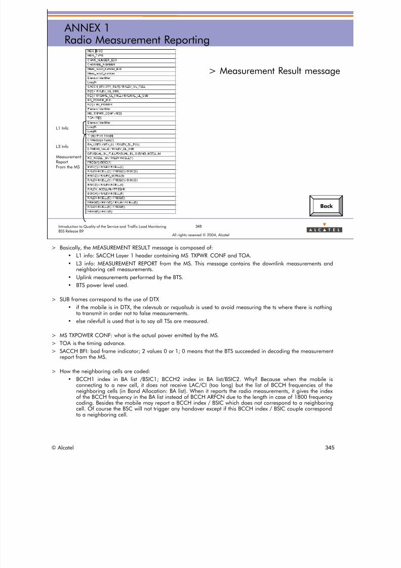
8/12/2019 QOS_B9 (Call Setup)
http://slidepdf.com/reader/full/qosb9-call-setup 345/388
345Introduction to Quality of the Service and Traffic Load MonitoringBSS Release B9
All rights reserved © 2004, Alcatel
ANNEX 1Radio Measurement Reporting
> Measurement Result message
L1 Info
L3 Info
Measurement
ReportFrom the MS
Back
> Basically, the MEASUREMENT RESULT message is composed of:
• L1 info: SACCH Layer 1 header containing MS_TXPWR_CONF and TOA.
• L3 info: MEASUREMENT REPORT from the MS. This message contains the downlink measurements andneighboring cell measurements.
• Uplink measurements performed by the BTS.
• BTS power level used.
> SUB frames correspond to the use of DTX
• if the mobile is in DTX, the rxlevsub or rxqualsub is used to avoid measuring the ts where there is nothingto transmit in order not to false measurements.
• else rxlevfull is used that is to say all TSs are measured.
> MS TXPOWER CONF: what is the actual power emitted by the MS. > TOA is the timing advance. > SACCH BFI: bad frame indicator; 2 values 0 or 1; 0 means that the BTS succeeded in decoding the measurement
report from the MS.
> How the neighboring cells are coded:
• BCCH1 index in BA list /BSIC1; BCCH2 index in BA list/BSIC2. Why? Because when the mobile isconnecting to a new cell, it does not receive LAC/CI (too long) but the list of BCCH frequencies of theneighboring cells (in Band Allocation: BA list). When it reports the radio measurements, it gives the indexof the BCCH frequency in the BA list instead of BCCH ARFCN due to the length in case of 1800 frequencycoding. Besides the mobile may report a BCCH index / BSIC which does not correspond to a neighboring
cell. Of course the BSC will not trigger any handover except if this BCCH index / BSIC couple correspondto a neighboring cell.
© Alcatel 345

8/12/2019 QOS_B9 (Call Setup)
http://slidepdf.com/reader/full/qosb9-call-setup 346/388
All rights reserved © 2004, Alcatel
ANNEX 2Extended Measurement Reporting (MAFA)
ANNEX 2
Extended Measurement Reporting(MAFA)
© Alcatel 346
8/12/2019 QOS_B9 (Call Setup)
http://slidepdf.com/reader/full/qosb9-call-setup 347/388
347Introduction to Quality of the Service and Traffic Load MonitoringBSS Release B9
All rights reserved © 2004, Alcatel
ANNEX 2Extended Measurement Reporting (MAFA)
> The Extended Measurement Reporting is a feature allowing the
BSS to request an MS to measure and report up to 21frequencies of the band that are not included in its BA list
> Such phase 2+ mobiles must support the optional MAFA feature(Mobile Assisted Frequency Allocation)
© Alcatel 347

8/12/2019 QOS_B9 (Call Setup)
http://slidepdf.com/reader/full/qosb9-call-setup 348/388
348Introduction to Quality of the Service and Traffic Load MonitoringBSS Release B9
All rights reserved © 2004, Alcatel
MS BTS BSC MSC
TCH ASSIGNMENT PHASE (OC or TC)< -----------------------------------
ASSIGNMENT REQUEST
< --------------------------------------------------------
PHYSICAL CONTEXT REQUEST
-------------------------------------------------------- >
PHYSICAL CONTEXT CONFIRM
< --------------------------------------------------------
CHANNEL ACTIVATION (TCH)
(EMO included)
-------------------------------------------------------- >
CHANNEL ACTIVATION ACKNOWLEDGE
.
.
TCH establishment.
--------TCH---------> .
ASSIGNT COMPLETE ------------------------------------ ------------------- >
ASSIGNMENT COMPLETE ----------------------------------- >
<------SACCH-------- ASSIGNMENT COMPLETE
--------SACCH------>
<------SACCH--------
--------SACCH------>
<-------SACCH--------
EMO
(MAFA freq. List)
--------SACCH------>
EMR
(MAFA freq. RxLev)
<------SACCH--------
--------SACCH------>
ANNEX 2Extended Measurement Reporting (MAFA)
Extended Measurement Reporting mechanisms• The Extended Measurement
Order includes the MAFA
frequencies the MS is askedto measure
• EMO sent once to the MSon SACCH after TCHseizure
• Extended MeasurementResults include the averagesignal level measured oneach MAFA frequency overone SACCH mf duration
• EMR received once per callon SACCH
Back
> When the BTS receives a CHANNEL ACTIVATION with the Extended Measurement Order(EMO) included, it shall send this information on the SACCH to the corresponding mobile onlyonce.
> When the BTS has to send this information, it shall replace the sending of system information5, 5bis, 5ter or 6 by this information. At the next SACCH multi-frame, the BTS shall resume thesending of this system information by the replaced one.
> The EMO shall be sent after 2 complete sets of SYS_INFO5 and 6, i.e. after the 2nd SYSINFO 6after the reception of SABM. This guarantees the MS has received a complete set.
> Then, the BTS normally receives from the MS an EXTENDED MEASUREMENT RESULT with thelevel of the frequencies to monitor. The BTS shall make the correlation between these levelsand the frequencies contained in the latest EMO information, after having decoded them,according to the order of the ARFCN. The ‘EXTENDED_MEASUREMENT_RESULT’ is NOTforwarded to the BSC, instead a ‘MEASUREMENT_RESULT’ with indication ‘no_MS_results’ issent to the BSC.
> In particular, the BTS shall identify the level of the BCCH frequency of the serving cell (whichshall always be part of the frequencies to monitor) and apply it as the RXLEV_DL in the RadioMeasurement Statistics. The other frequencies will be considered in the same way as BCCHfrequency of neighboring cells: they will be linked to the neighboring level and C/I statistics.
© Alcatel 348

8/12/2019 QOS_B9 (Call Setup)
http://slidepdf.com/reader/full/qosb9-call-setup 349/388
All rights reserved © 2004, Alcatel
ANNEX 3:Directed Retry Indicators
ANNEX 3
Directed Retry Indicators
© Alcatel 349

8/12/2019 QOS_B9 (Call Setup)
http://slidepdf.com/reader/full/qosb9-call-setup 350/388
350Introduction to Quality of the Service and Traffic Load MonitoringBSS Release B9
All rights reserved © 2004, Alcatel
ANNEX 3:Directed Retry IndicatorsInternal DR - success case
> DR FAIL. CASES > internal DR >success case
> The same internal DR procedure
leads to an incrementation of twosets of counters:
> incoming DR counters for the targetcell: MC153, MC151, etc.
> outgoing DR counters for theserving cell: MC144E, MC142E,etc.
> MCx counters belong to StandardType 110 reported permanently
> Cx counters belong to Detailed Type29 reported on demand.
> Standard type from B8.
MS serving cell target cell BSC MSC
TCH ASSIGNMENT PHASE (OC or TC)
< -----------------------
ASSIGNMENT
REQUEST
No free TCHTCH request queued
Queuing allowed
Start T11 ----------------------- >QUEUING_INDIC.
MC13A
IDR condition met MC153, MC144e,
CHANNEL ACTIV. (TCH)
<--------------------------------- MC15A
CHAN ACTIV ACK
---------------------------------->
HO CMD HANDOVER COMMAND
<---------------------
(SDCCH)
<----------------------------------------------------------------------- start T3103
C154, MC607
start T3124 C145A+C145C
HANDOVER ACCESS
------------------------(TCH)---------------------------->
-------------------------------------------------------------> HO DETECTION
PHYSICAL INFORMATION ---------------------------------->
<------------------------------------------------------------ start T3105
stop T3124
start T200
------------------------ SABM --------------------------> stop T3105
<-------------------------- UA ---------------------------- ESTABLISH INDICATION
stop T200 ---------------------------------->
HANDOVER COMPLETE HO CMP stop T3103
-------------------------------------------------------------> ----------------------------------> ASSIGNMENTCOMPLETE
------------------------>
Release of old SDCCH MC151,MC717A,MC142e
> The following DR counters are provided in Type 110
• for the target cell:
– MC13A: TCH requests for Normal Assignment that are put into the queue,
– MC153: incoming internal DR requests,
– MC15A: TCH allocations for incoming internal DR,
– MC151: incoming internal DR successes per cell,
– MC717A: incoming internal DR successes per TRX.
• for the serving cell:
– MC144E: outgoing internal DR requests,
– MC142E: outgoing internal DR successes,
– MC607: outgoing internal+external DR attempts.
> The following DR counters are provided in Type 29 (this type becomes a standard type in B8)
• for the target cell:– C153: incoming internal DR requests,
– C154: incoming internal DR attempts,
– C151: incoming internal DR successes.
• for the serving cell:
– C144A: forced outgoing internal DR requests,
– C144C: normal outgoing internal DR requests,
– C145A: forced outgoing internal DR attempts,
– C145C: normal outgoing internal DR attempts,
– C142A: forced outgoing internal DR successes,
– C142C: normal outgoing internal DR successes.
> All the counters here and in the next slides concerning directed retry and relative to type 29 can be activated for all cells of theBSC at once from B8. (Type 29 becomes a standard type in B8):C142a, C142b, C142c, C142d, C143a, C143b, C143c, C143d, C143e, C143f, C143g, C143h, C144a, C144b,C144c, C144d, C145a, C145b, C145c, C145d, C151, C152,C153, C154, C555
© Alcatel 350

8/12/2019 QOS_B9 (Call Setup)
http://slidepdf.com/reader/full/qosb9-call-setup 351/388
351Introduction to Quality of the Service and Traffic Load MonitoringBSS Release B9
All rights reserved © 2004, Alcatel
ANNEX 3:Directed Retry IndicatorsIncoming internal DR - failures
DR FAIL. CASES > Incoming internal DR failures:
Directed Retry procedure from the target cell point of view
> DR Preparation:
• congestion: no RTCH available in the target cell
– does not concern the outgoing side (serving cell point of view)
• BSS problem (no specific counter)
> DR Execution:
• radio problem: the MS fails to access the new channel– the reversion/drop discrimination concerns only the serving cell
• BSS problem (no specific counter)
© Alcatel 351

8/12/2019 QOS_B9 (Call Setup)
http://slidepdf.com/reader/full/qosb9-call-setup 352/388
352Introduction to Quality of the Service and Traffic Load MonitoringBSS Release B9
All rights reserved © 2004, Alcatel
ANNEX 3:Directed Retry IndicatorsIncoming internal DR - congestion
DR FAIL. CASES > Incoming internal DR fail: congestionMC555=C155
Standard Type
MS serving cell target cell BSC MSC
TCH ASSIGNMENT PHASE (OC or TC)
< ----------------------------------------------------
ASSIGNMENT REQUEST
No free TCHIn serving cell
Queuing allowed
Start T11 --------------------------------------------------- >
QUEUING_INDIC.MC13A
IDR condition met MC153, MC144e,MC607
No free TCHIn target cell
MC555
> C155 is available in Type 29.
© Alcatel 352

8/12/2019 QOS_B9 (Call Setup)
http://slidepdf.com/reader/full/qosb9-call-setup 353/388
MS s
MEAS REP
HO CMD
353Introduction to Quality of the Service and Traffic Load MonitoringBSS Release B9
All rights reserved © 2004, Alcatel
ANNEX 3:Directed Retry IndicatorsIncoming internal DR - radio failure
DR FAIL. CASES > Incoming internal DR fail: MS access problem
erving cell target cell BSC MSC
-----------------------> MEASUREMENT RESULT
------------------------------------------------------------------------>
CHANNEL ACTIVATION
<---------------------------------
CHANNEL ACTIV ACK
---------------------------------->
HANDOVER COMMAND
<---------------------- <----------------------------------------------------------------------- start T3103
C154
SABM
-----------x T3103 expiry
C152
MS Serving cell Target Cell BSC
HO CMD HANDOVER COMMAND
<---------------------- <----------------------------------------------------------------------- start T3103
HANDOVER ACCESS C154
------------------------------------------------------------->
-------------------------------------------------------------> HO DETECTION
PHYSICAL INFORMATION ---------------------------------->
<------------------------------------------------------------ start T3105
SABM
-------------------------------------------------------------> ESTABLISH INDICATION
UA ---------------------------------->
<------------------------------------------------------------ stop T3105
HANDOVER COMPLETE
----------------------------------------------------- - - - -X
SABM
-----------------------> ESTABLISH INDICATION
UA ------------------------------------------------------------------------>
<----------------------
HO FAILURE HANDOVER FAILURE
-----------------------> ------------------------------------------------------------------------> C152
Release of new channel
> All incoming internal DR failures due to radio problems are counted in the same counterC152.
> This counter is provided in Type 29 > Both radio failures with Reversion Old SDCCH Channel and radio drop are counted together.
© Alcatel 353

8/12/2019 QOS_B9 (Call Setup)
http://slidepdf.com/reader/full/qosb9-call-setup 354/388
354Introduction to Quality of the Service and Traffic Load MonitoringBSS Release B9
All rights reserved © 2004, Alcatel
ANNEX 3:Directed Retry IndicatorsIncoming internal DR - counters
DR FAIL. CASES > Incoming internal DR counters
Request MC153, C153
Congestion MC555, C155
BSS Pb C153-C154-C155
Attempt C154
Radio (MS access problem) C152
BSS Pb C154-C151-C152
Success MC151, C151
Execution
Preparation
INCOMING INTERNAL Directed Retry
REQUEST
CONGESTION
ATTEMPT
MS ACCESS PB
BSS PB
SUCCESS
BSS PB
Preparation Failure
Execution Failure
Type 29 counters becomes a standard (PMC)
> All MCxxx counters are available in Type 110.
> All Cxxx counters are available in Type 29.
> Type 29 counters becomes a standard in B8.
© Alcatel 354

8/12/2019 QOS_B9 (Call Setup)
http://slidepdf.com/reader/full/qosb9-call-setup 355/388
> Refer to BSS - DEFINITION OF QUALITY OF SERVICE INDICATORS
• Specific indicators for densification techniques > Directed Retry > Incoming DR
– DRIBCAR: efficiency of the incoming internal DR preparation = MC15A/MC153
– DRIBCNR: rate of incoming internal DR failures due to congestion = MC155/MC153
– DRIBEFR: efficiency of the incoming internal DR execution = MC717A/MC153
• Other indicators can be computed from Type 110 counters:
– DRIBSUR: global efficiency of incoming internal DR = MC717A/MC153 = MC151/MC153
from Type 29 counters
– rate of incoming internal DR preparation failures due to BSS problems= (C153-C154-C155)/C153
– rate of incoming internal DR execution failures due to BSS problems= (C154-C151-C152)/C154
– rate of incoming internal DR execution failures due to radio access problems= C152/C154
© Alcatel 355

8/12/2019 QOS_B9 (Call Setup)
http://slidepdf.com/reader/full/qosb9-call-setup 356/388
356Introduction to Quality of the Service and Traffic Load MonitoringBSS Release B9
All rights reserved © 2004, Alcatel
ANNEX 3:Directed Retry IndicatorsOutgoing internal DR - failures
DR FAIL. CASES > Outgoing internal DR failures
Directed Retry procedure from the serving cell point of view
> DR Preparation:
• congestion on the target cell (no specific counter on the servingcell)
• BSS problem (no specific counter)
> DR Execution:
• radio problem: the MS reverts to the old channel
• radio problem: the MS drops
• BSS problem (no specific counter)
© Alcatel 356
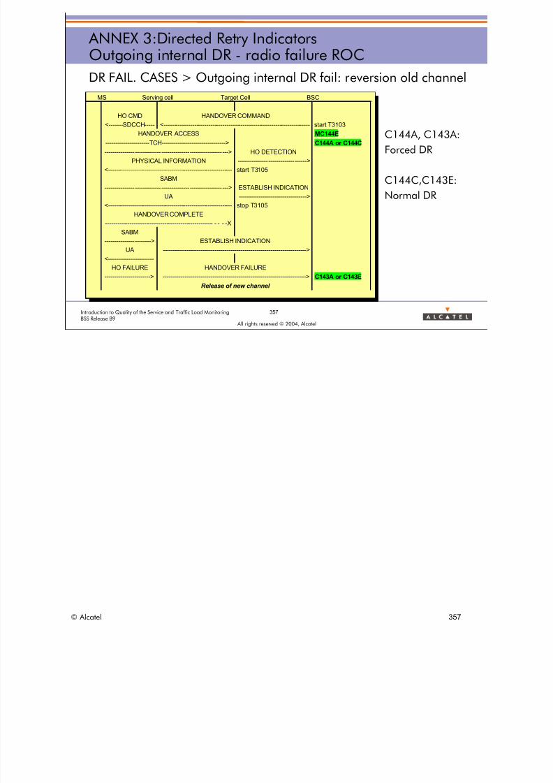
8/12/2019 QOS_B9 (Call Setup)
http://slidepdf.com/reader/full/qosb9-call-setup 357/388
357Introduction to Quality of the Service and Traffic Load MonitoringBSS Release B9
All rights reserved © 2004, Alcatel
ANNEX 3:Directed Retry IndicatorsOutgoing internal DR - radio failure ROC
DR FAIL. CASES > Outgoing internal DR fail: reversion old channel
C144A, C143A:
Forced DR
C144C,C143E:
Normal DR
MS Serving cell Target Cell BSC
HO CMD HANDOVER COMMAND
<-------SDCCH---- <----------------------------------------------------------------------- start T3103
HANDOVER ACCESS MC144E
----------------------TCH--------------------------------> C144A or C144C
-------------------------------------------------------------> HO DETECTION
PHYSICAL INFORMATION ---------------------------------->
<------------------------------------------------------------ start T3105
SABM
-------------------------------------------------------------> ESTABLISH INDICATION
UA ---------------------------------->
<------------------------------------------------------------ stop T3105
HANDOVER COMPLETE
----------------------------------------------------- - - - -XSABM
-----------------------> ESTABLISH INDICATION
UA ------------------------------------------------------------------------>
<----------------------
HO FAILURE HANDOVER FAILURE
-----------------------> ------------------------------------------------------------------------> C143A or C143E
Release of new channel
© Alcatel 357
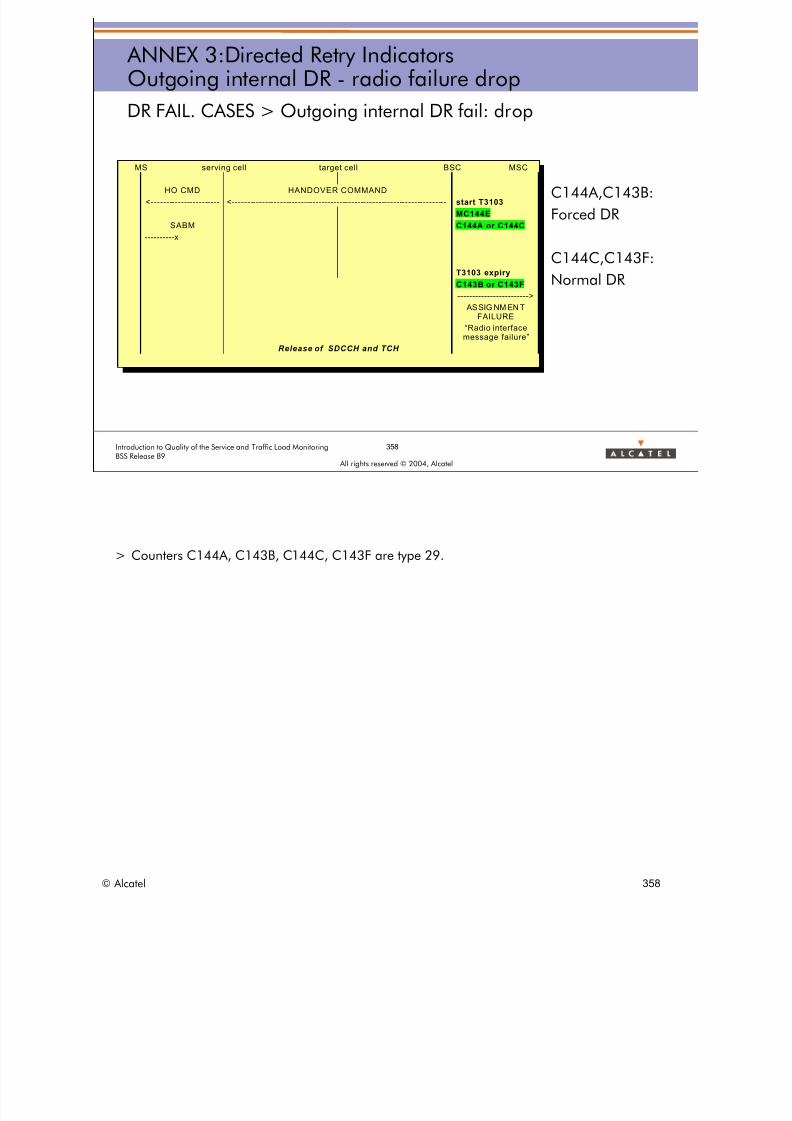
8/12/2019 QOS_B9 (Call Setup)
http://slidepdf.com/reader/full/qosb9-call-setup 358/388
358Introduction to Quality of the Service and Traffic Load MonitoringBSS Release B9
All rights reserved © 2004, Alcatel
ANNEX 3:Directed Retry IndicatorsOutgoing internal DR - radio failure drop
DR FAIL. CASES > Outgoing internal DR fail: drop
C144A,C143B:
Forced DR
C144C,C143F:
Normal DR
MS serving cell target cell BSC MSC
HO CMD HANDOVER COMMAND
<---------------------- <----------------------------------------------------------------------- start T3103
MC144E
SABM C144A or C144C
----------x
T3103 expiry
C143B or C143F
------------------------>
ASSIG NM EN TFAILURE
“Radio interfacemessage failure”
Release of SDCCH and TCH
> Counters C144A, C143B, C144C, C143F are type 29.
© Alcatel 358

8/12/2019 QOS_B9 (Call Setup)
http://slidepdf.com/reader/full/qosb9-call-setup 359/388
359Introduction to Quality of the Service and Traffic Load MonitoringBSS Release B9
All rights reserved © 2004, Alcatel
ANNEX 3:Directed Retry IndicatorsOutgoing internal DR - counters
DR FAIL. CASES > Outgoing internal DR counters
Preparation Request MC144E, C144A+C144C
Any preparation failure (C144A+C144C) - (C145A+C145C)
Attempt C145A+C145C
Reversion old channel C143A+C143E
Drop radio C143B+C143F
BSS Pb (C145A+C145C) - (C143A+C143E+C143B+C143F)
Success MC142E, C142A+C142C
Execution
OUTGOING INTERNAL Directed Retry
REQUEST
CONGESTION
ATTEMPT
REVERSION OLD CHANNEL
DROP RADIO
BSS PB
SUCCESS
BSS PB
Preparation Failure
Execution Failure
© Alcatel 359

8/12/2019 QOS_B9 (Call Setup)
http://slidepdf.com/reader/full/qosb9-call-setup 360/388
> Refer to BSS - DEFINITION OF QUALITY OF SERVICE INDICATORS
• Specific indicators for densification techniques > Directed Retry > Outgoing DR
– DROBSUR: global efficiency of outgoing internal DR = MC142E/MC144E
• Other indicators can be computed from Type 29 counters:
– efficiency of the outgoing internal DR preparation = (C145A+C145C)/(C144A+C144C)
– efficiency of the outgoing internal DR execution = (C142A+C142C)/(C145A+C145C)
– rate of outgoing internal DR execution failures due to BSS problems= [(C145A+C145C) - (C143A+C143E+C143B+C143F)] / (C145A+C145C)
– rate of outgoing internal DR execution failures due to radio problems with reversion oldchannel= (C143A+C143E) / (C145A+C145C)
– rate of outgoing internal DR execution failures due to radio problems with drop= (C143B+C143F) / (C145A+C145C)
type 29 counters are defined:
– DRFOSUIN C142a NB_OUT_FORCED_IDR_SUCC
– DRFOSUEN C142b NB_OUT_FORCED_EDR_SUCC
– DROBSUIN C142c NB_OUT_NOR_IDR_SUCC
– DROMSUEN C142d NB_OUT_NOR_EDR_SUCC
– DRFORDIN C144a NB_OUT_FORCED_IDR_REQ– DRFORDEN C144b NB_OUT_FORCED_EDR_REQ
– DROBRDIN C144c NB_OUT_NOR_IDR_REQ
– DROMRDEN C144d NB_OUT_NOR_EDR_REQ
– DROBRQIN C145c NB_OUT_NOR_IDR_ATPT
– DROMRQEN C145d NB_OUT_NOR_EDR_ATPT
© Alcatel 360
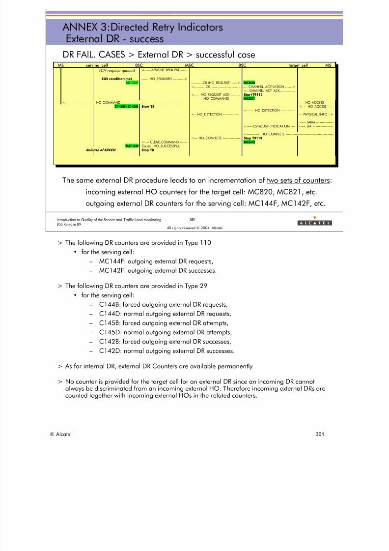
8/12/2019 QOS_B9 (Call Setup)
http://slidepdf.com/reader/full/qosb9-call-setup 361/388
361Introduction to Quality of the Service and Traffic Load MonitoringBSS Release B9
All rights reserved © 2004, Alcatel
ANNEX 3:Directed Retry IndicatorsExternal DR - success
DR FAIL. CASES > External DR > successful case
The same external DR procedure leads to an incrementation of two sets of counters:
incoming external HO counters for the target cell: MC820, MC821, etc.
outgoing external DR counters for the serving cell: MC144F, MC142F, etc.
MS serving_cell BSC MSC BSC target_cell MS
TCH request queued <------ASSIGNT REQUEST------
EDR condition met ------ HO_REQUIRED ---------->MC144F ----------CR (HO_REQUEST) -----> MC820
<--------- CC ----------------------- ---- CHANNEL_ACTIVATION ------><- CHANNEL_ACT_ACK------------
<----- HO_REQUEST_ACK ------- Start T9113(HO_COMMAND) MC821
<------------------------- HO_COMMAND ----------------------------------------------------- <---- HO_ACCESS ----C145B+C145D Start T8 <---- HO_ACCESS ----
<------ HO_DETECTION-------------<-- HO_DETECTION ------------- --- PHYSICAL_INFO -->
<--- SABM --------------<----- ESTABLISH_INDICATION --- ----- UA -------------->
<----------- HO_COMPLETE --------------- ---------- ---------- ----<--- HO_COMPLETE -------------- Stop T9113
<---- CLEAR_COMMAND ----- MC642MC142F Cause : HO_SUCCESSFUL
Release of SDCCH Stop T8
> The following DR counters are provided in Type 110
• for the serving cell:
– MC144F: outgoing external DR requests,
– MC142F: outgoing external DR successes.
> The following DR counters are provided in Type 29
• for the serving cell:
– C144B: forced outgoing external DR requests,
– C144D: normal outgoing external DR requests,– C145B: forced outgoing external DR attempts,
– C145D: normal outgoing external DR attempts,
– C142B: forced outgoing external DR successes,
– C142D: normal outgoing external DR successes.
> As for internal DR, external DR Counters are available permanently
> No counter is provided for the target cell for an external DR since an incoming DR cannotalways be discriminated from an incoming external HO. Therefore incoming external DRs are
counted together with incoming external HOs in the related counters.
© Alcatel 361
8/12/2019 QOS_B9 (Call Setup)
http://slidepdf.com/reader/full/qosb9-call-setup 362/388
362Introduction to Quality of the Service and Traffic Load MonitoringBSS Release B9
All rights reserved © 2004, Alcatel
ANNEX 3:Directed Retry IndicatorsOutgoing external DR - failures
DR FAIL. CASES > Outgoing external DR failures
Directed Retry procedure from the serving cell point of view
> DR Preparation:
• congestion on the target cell (no specific counter on the servingcell)
• BSS problem (no specific counter)
> DR Execution:
• radio problem: the MS reverts to the old channel
• radio problem: the MS drops
• BSS problem (no specific counter)
© Alcatel 362

8/12/2019 QOS_B9 (Call Setup)
http://slidepdf.com/reader/full/qosb9-call-setup 363/388
363Introduction to Quality of the Service and Traffic Load MonitoringBSS Release B9
All rights reserved © 2004, Alcatel
ANNEX 3:Directed Retry IndicatorsOutgoing external DR - radio failure ROC
DR FAIL. CASES > Outgoing external DR fail: reversion old channel
C145B,C143C: Forced DR
C145D,C143G: Normal DR
MS serving_cell BSC MSC BSC target_cell MS ASSIGNT REQUEST
---------------------> TCH request queuedEDR condition met ---- HO_REQUIRED ------->
MC144F ----------CR (HO_REQUEST) ------------------ -><-------- CC -------------------------------------- - CHANNEL_ACT ---------->
<--- CHA_ACT_ACK -------<----- HO_REQUEST_ACK---------------------- Start T9113(HO-COMMAND) included
<-------------------------- HO_COMMAND -----------------------------------------------Start T8 X --- HO_ACCESS ----
C145B+C145D X ---- HO_ACCESS --------- SABM --------><--- UA ------------ -- ESTABLISH_INDICATION->
----- HO_FAILURE (reversion to old channel) ---------- ----------- ------------ --------->C143C+C143G ----- CLEAR_COMMAND ---------------------->
Radio interface fail : Reversion to old channelRelease of connection
© Alcatel 363

8/12/2019 QOS_B9 (Call Setup)
http://slidepdf.com/reader/full/qosb9-call-setup 364/388
364Introduction to Quality of the Service and Traffic Load MonitoringBSS Release B9
All rights reserved © 2004, Alcatel
ANNEX 3:Directed Retry IndicatorsOutgoing external DR - radio failure drop
DR FAIL. CASES > Outgoing external DR fail: drop
C145B,C143D: Forced DR
C145D,C143H: Normal DR
MS serving_cell BSC MSC BSC target_cell MS ASSIGNT REQUEST---------------------> TCH request queued
EDR condition met ---- HO_REQUIRED ------->MC144F ----------CR (HO_REQUEST) ---------------- --->
<-------- CC -------------------------------------- - CHANNEL_ACT ----------><--- CHA_ACT_ACK -------
<----- HO_REQUEST_ACK---------------------- Start T9113(HO-COMMAND) included
<-------------------------- HO_COMMAND --------- ----------- ---------- ----------- ------Start T8 X --- HO_ACCESS ----
C145B+C145D X ---- HO_ACCESS --------- SABM --- X----- SABM --- X
----- SABM --- X
T8 expiry ----- CLEAR_REQUEST ->C143D+C143H Radio interface message fail
Release of connection
© Alcatel 364

8/12/2019 QOS_B9 (Call Setup)
http://slidepdf.com/reader/full/qosb9-call-setup 365/388
© Alcatel 365
365Introduction to Quality of the Service and Traffic Load MonitoringBSS Release B9
All rights reserved © 2004, Alcatel
ANNEX 3:Directed Retry IndicatorsOutgoing external DR - counters
DR FAIL. CASES > Outgoing external DR counters
Preparation Request MC144F, C144B+C144D
Any preparation failure (C144B+C144D) - (C145B+C145D)
Attempt C145B+C145D
Reversion old channel C143C+C143G
Drop radio C143D+C143H
BSS Pb (C145+C145D) - (C143C+C143G+C143D+C143H)
Success MC142F, C142B+C142D
Execution
OUTGOING EXTERNAL Directed Retry
REQUEST
CONGESTION
ATTEMPT
REVERSION OLD CHANNEL
DROP RADIO
BSS PB
SUCCESS
BSS PB
Preparation Failure
Execution Failure

8/12/2019 QOS_B9 (Call Setup)
http://slidepdf.com/reader/full/qosb9-call-setup 366/388
> Refer to BSS - DEFINITION OF QUALITY OF SERVICE INDICATORS
• Specific indicators for densification techniques > Directed Retry > Outgoing DR
– DROMSUR: global efficiency of outgoing external DR = MC142F/MC144F
• Other indicators can be computed from Type 29 counters:
– efficiency of the outgoing internal DR preparation = (C145B+C145D)/(C144B+C144D)
– efficiency of the outgoing internal DR execution = (C142B+C142D)/(C145B+C145D)
– rate of outgoing internal DR execution failures due to BSS problems= [(C145B+C145D) - (C143C+C143G+C143D+C143H)] / (C145B+C145D)
– rate of outgoing internal DR execution failures due to radio problems with reversion oldchannel= (C143C+C143G) / (C145B+C145D)
– rate of outgoing internal DR execution failures due to radio problems with drop= (C143D+C143H) / (C145B+C145D)
• Interesting indicator:
– TCQUSUDSR: rate of outgoing internal and external directed retries (forced + normal)successfully performed over all RTCH requests queued during normal assignment.
© Alcatel 366

8/12/2019 QOS_B9 (Call Setup)
http://slidepdf.com/reader/full/qosb9-call-setup 367/388
All rights reserved © 2004, Alcatel
ANNEX 4GSM BSS Protocol Stacks
ANNEX 4
GSM BSS Protocol Stacks
© Alcatel 367
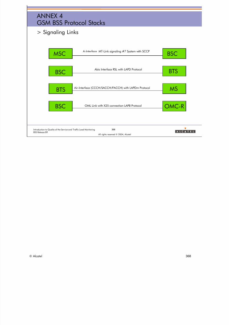
8/12/2019 QOS_B9 (Call Setup)
http://slidepdf.com/reader/full/qosb9-call-setup 368/388
368Introduction to Quality of the Service and Traffic Load MonitoringBSS Release B9
All rights reserved © 2004, Alcatel
ANNEX 4GSM BSS Protocol Stacks
> Signaling Links
A-Interface MT-Link signaling #7 System with SCCPMSC BSC
BSC BTS Abis Interface RSL with LAPD Protocol
BTS MS Air-Interface (CCCH/SACCH/FACCH) with LAPDm Protocol
BSC OMC-ROML Link with X25 connection LAPB Protocol
© Alcatel 368

8/12/2019 QOS_B9 (Call Setup)
http://slidepdf.com/reader/full/qosb9-call-setup 369/388
369Introduction to Quality of the Service and Traffic Load MonitoringBSS Release B9
All rights reserved © 2004, Alcatel
ANNEX 4GSM BSS Protocol Stacks
> The reference Model
7 Application
6 Presentation
4 Transport
5 Session
2 Data Link
3 Network
1 Physical
User of Transport Service
Transport ServiceNetworkService
© Alcatel 369
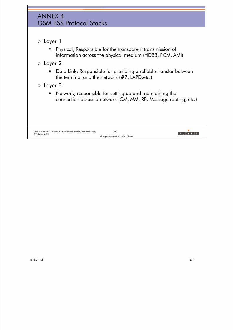
8/12/2019 QOS_B9 (Call Setup)
http://slidepdf.com/reader/full/qosb9-call-setup 370/388
370Introduction to Quality of the Service and Traffic Load MonitoringBSS Release B9
All rights reserved © 2004, Alcatel
ANNEX 4GSM BSS Protocol Stacks
> Layer 1
• Physical; Responsible for the transparent transmission ofinformation across the physical medium (HDB3, PCM, AMI)
> Layer 2
• Data Link; Responsible for providing a reliable transfer betweenthe terminal and the network (#7, LAPD,etc.)
> Layer 3
• Network; responsible for setting up and maintaining theconnection across a network (CM, MM, RR, Message routing, etc.)
© Alcatel 370
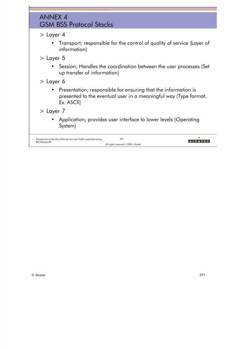
8/12/2019 QOS_B9 (Call Setup)
http://slidepdf.com/reader/full/qosb9-call-setup 371/388
371Introduction to Quality of the Service and Traffic Load MonitoringBSS Release B9
All rights reserved © 2004, Alcatel
ANNEX 4GSM BSS Protocol Stacks
> Layer 4
• Transport; responsible for the control of quality of service (Layer of
information)> Layer 5
• Session; Handles the coordination between the user processes (Setup transfer of information)
> Layer 6
• Presentation; responsible for ensuring that the information ispresented to the eventual user in a meaningful way (Type format.Ex. ASCII)
> Layer 7
• Application; provides user interface to lower levels (OperatingSystem)
© Alcatel 371
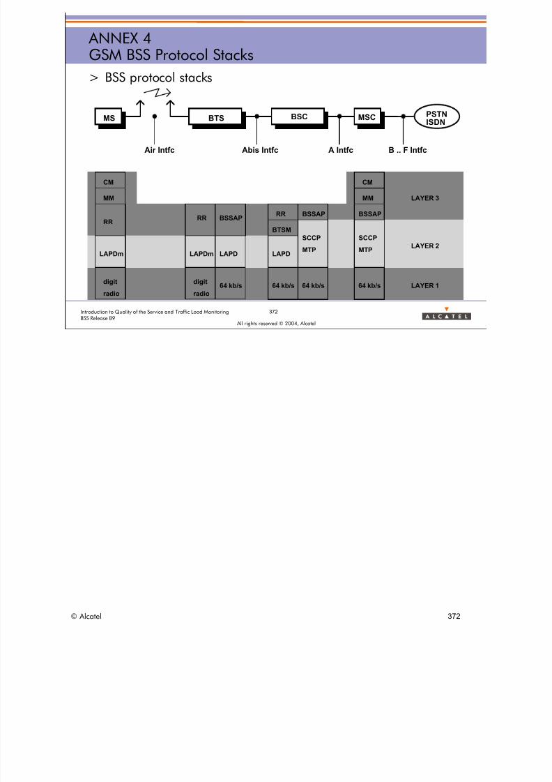
8/12/2019 QOS_B9 (Call Setup)
http://slidepdf.com/reader/full/qosb9-call-setup 372/388
372Introduction to Quality of the Service and Traffic Load MonitoringBSS Release B9
All rights reserved © 2004, Alcatel
ANNEX 4GSM BSS Protocol Stacks
> BSS protocol stacks
BTS PSTNISDN
Air Intfc Abis Intfc A Intfc B .. F Intfc
MS BSC MSC
CM
MM
RR
LAPDm
digit
radio
RR BSSAP
LAPDm LAPD
digit
radio
64 kb/s 64 kb/s 64 kb/s 64 kb/s
LAPD
RR
BTSM
BSSAP
CM
MM
BSSAP
SCCP
MTP
SCCP
MTPLAYER 2
LAYER 1
LAYER 3
© Alcatel 372

8/12/2019 QOS_B9 (Call Setup)
http://slidepdf.com/reader/full/qosb9-call-setup 373/388
373Introduction to Quality of the Service and Traffic Load MonitoringBSS Release B9
All rights reserved © 2004, Alcatel
ANNEX 4GSM BSS Protocol Stacks
> BSS protocol stacks (detailed)
SSCS
SSTM 3
SSTM 2
SSCS
SSTM 3
SSTM 2
SSGT
MAP
SSGT
MAP
SSCS
SSTM 3
SSTM 2
PCM TS
DTAP
SSCS
SSTM 3
SSTM 2
PCM TS
DTAP
LAPDLAPDm LAPD
SS (SMS)SS (SMS)
BSSMAP
MM
CC
BSSMAPRR
RR
RR' BTSMBTSM
LAPDm
(SMS)
SSCC
MM
(Relay)
MS BTS BSC MSC / VLR NSS(ex. : HLR)
Um A bis A (D)
1
2
3
(Relay
64 kbit/s
or PCM TS64 kbit/s
or PCM TSPCM TS PCM TS
PhycalLayer
PhycalLayer
© Alcatel 373
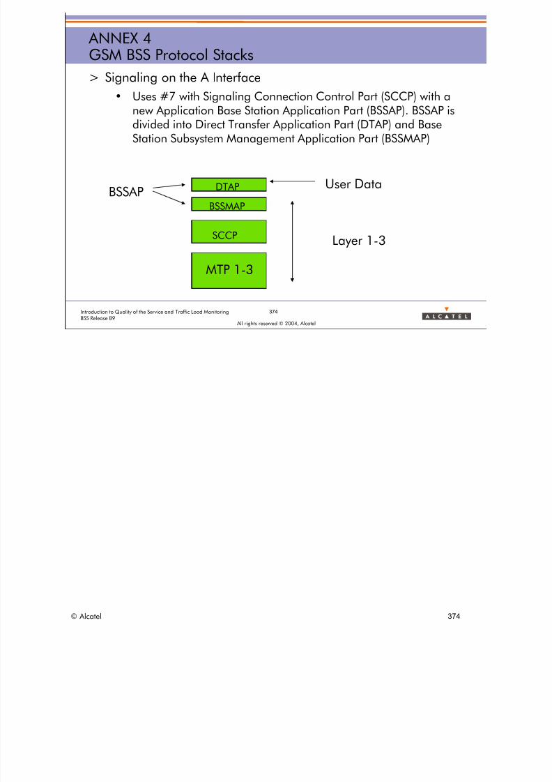
8/12/2019 QOS_B9 (Call Setup)
http://slidepdf.com/reader/full/qosb9-call-setup 374/388
© Alcatel 374
374Introduction to Quality of the Service and Traffic Load MonitoringBSS Release B9
All rights reserved © 2004, Alcatel
ANNEX 4GSM BSS Protocol Stacks
> Signaling on the A Interface
• Uses #7 with Signaling Connection Control Part (SCCP) with a
new Application Base Station Application Part (BSSAP). BSSAP isdivided into Direct Transfer Application Part (DTAP) and BaseStation Subsystem Management Application Part (BSSMAP)
DTAP
BSSMAP
SCCP
MTP 1-3
User Data
Layer 1-3
BSSAP

8/12/2019 QOS_B9 (Call Setup)
http://slidepdf.com/reader/full/qosb9-call-setup 375/388
375Introduction to Quality of the Service and Traffic Load MonitoringBSS Release B9
All rights reserved © 2004, Alcatel
ANNEX 4GSM BSS Protocol Stacks
> BSSMAP
• Contains the messages, which are exchanged between the BSC
and the MSC and which are evaluated from the BSC.• In fact all the messages, which are exchanged as RR (Radio
Resource Management Services between the MSC, BSC and MS). Also control Information concerning the MSC and BSC.
• Example: Paging, HND_CMD, Reset
> DTAP
• Messages which are exchanged between an NSS and an MStransparent. In this case, the BSC transfers the messages withoutevaluation transparent. Mainly Messages from MobilityManagement (MM) and Call control (CC)
© Alcatel 375

8/12/2019 QOS_B9 (Call Setup)
http://slidepdf.com/reader/full/qosb9-call-setup 376/388
© Alcatel 376
376Introduction to Quality of the Service and Traffic Load MonitoringBSS Release B9
All rights reserved © 2004, Alcatel
ANNEX 4GSM BSS Protocol Stacks
> Relationship between DTAP, CC, MM, BSSMAP, RR
MSBSS MSC
Call Control (CC) DTAP
Radio Resource (RR)BSSMAP
Back

8/12/2019 QOS_B9 (Call Setup)
http://slidepdf.com/reader/full/qosb9-call-setup 377/388
All rights reserved © 2004, Alcatel
ANNEX 5LCS
ANNEX 5
LCS
© Alcatel 377
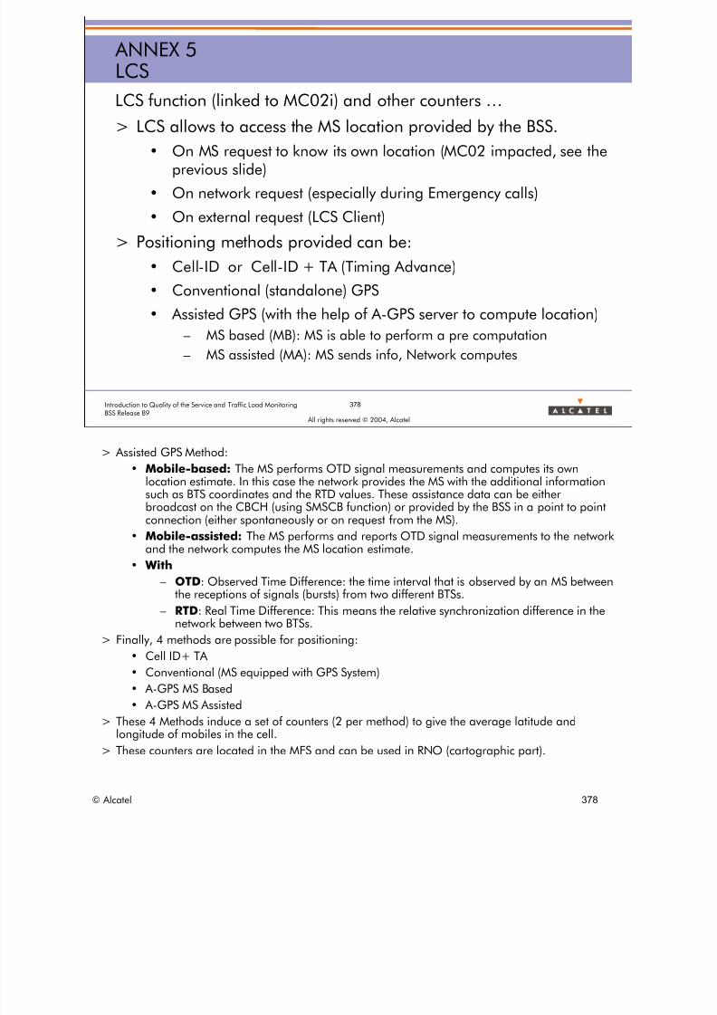
8/12/2019 QOS_B9 (Call Setup)
http://slidepdf.com/reader/full/qosb9-call-setup 378/388
378Introduction to Quality of the Service and Traffic Load MonitoringBSS Release B9
All rights reserved © 2004, Alcatel
ANNEX 5LCS
LCS function (linked to MC02i) and other counters …
> LCS allows to access the MS location provided by the BSS.
• On MS request to know its own location (MC02 impacted, see theprevious slide)
• On network request (especially during Emergency calls)
• On external request (LCS Client)
> Positioning methods provided can be:
• Cell-ID or Cell-ID + TA (Timing Advance)
• Conventional (standalone) GPS• Assisted GPS (with the help of A-GPS server to compute location)
– MS based (MB): MS is able to perform a pre computation
– MS assisted (MA): MS sends info, Network computes
> Assisted GPS Method:
• Mobile-based: The MS performs OTD signal measurements and computes its ownlocation estimate. In this case the network provides the MS with the additional informationsuch as BTS coordinates and the RTD values. These assistance data can be eitherbroadcast on the CBCH (using SMSCB function) or provided by the BSS in a point to pointconnection (either spontaneously or on request from the MS).
• Mobile-assisted: The MS performs and reports OTD signal measurements to the networkand the network computes the MS location estimate.
• With
– OTD: Observed Time Difference: the time interval that is observed by an MS betweenthe receptions of signals (bursts) from two different BTSs.
– RTD: Real Time Difference: This means the relative synchronization difference in thenetwork between two BTSs.
> Finally, 4 methods are possible for positioning:
• Cell ID+ TA
• Conventional (MS equipped with GPS System)
• A-GPS MS Based
• A-GPS MS Assisted
> These 4 Methods induce a set of counters (2 per method) to give the average latitude andlongitude of mobiles in the cell.
> These counters are located in the MFS and can be used in RNO (cartographic part).
© Alcatel 378
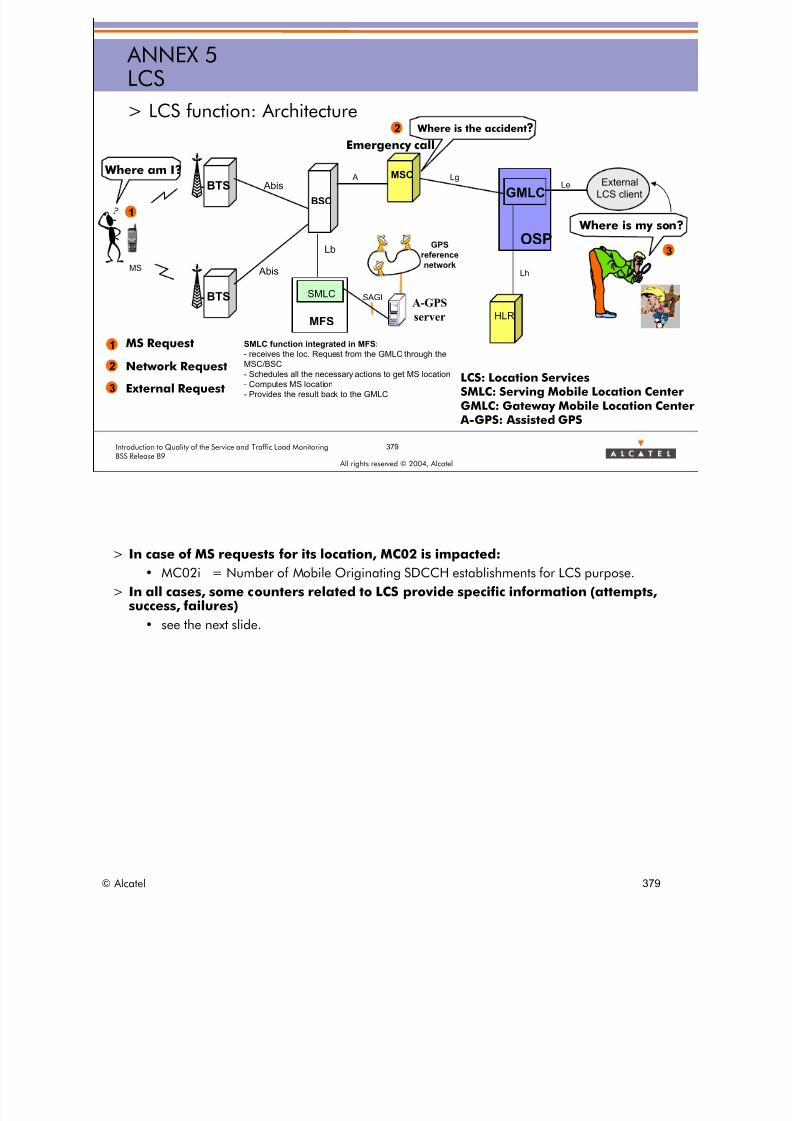
8/12/2019 QOS_B9 (Call Setup)
http://slidepdf.com/reader/full/qosb9-call-setup 379/388
379Introduction to Quality of the Service and Traffic Load MonitoringBSS Release B9
All rights reserved © 2004, Alcatel
ANNEX 5LCS
> LCS function: Architecture
SMLCBTS
BTS
MS
BSC
MSC
HLR
GMLC
OSP
Lg
Lh
External
LCS clientLe
A Abis
Abis
Lb
SMLC function integrated in MFS:
- receives the loc. Request from the GMLC through the
MSC/BSC
- Schedules all the necessary actions to get MS location
- Computes MS location
- Provides the result back to the GMLC
MFS
A-GPS
server
SAGI
GPS
reference
network
LCS: Location ServicesSMLC: Serving Mobile Location CenterGMLC: Gateway Mobile Location Center
A-GPS: Assisted GPS
Where is my son?
Where is the accident?
Emergency call
2
Where am I?
1
3
MS Request
Network Request
External Request3
2
1
> In case of MS requests for its location, MC02 is impacted:
• MC02i = Number of Mobile Originating SDCCH establishments for LCS purpose.
> In all cases, some counters related to LCS provide specific information (attempts,success, failures)
• see the next slide.
© Alcatel 379

8/12/2019 QOS_B9 (Call Setup)
http://slidepdf.com/reader/full/qosb9-call-setup 380/388
380Introduction to Quality of the Service and Traffic Load MonitoringBSS Release B9
All rights reserved © 2004, Alcatel
ANNEX 5LCSExample: Mobile terminated location request failure / success (External request)
SMLCMS BSCBTS LCS ClientMSC
BSSAP-LE Perform_Location_Request
.
GMLC
BSSMAP Perform_Location_Request
BSSAP-LE Perform_Location_Response
BSSMAP Perform_Location_Response
BSSMAP Clear Command and Release
Adequat positionning method chosen by SMLC
HLR
Paging
Authentication + Ciphering
LCS Service Response
LCS Service Request
Send_Routing_Info rqst
Send_Routing_Info resp
Provide_Subscriber_Location
Provide_Subscriber_Location Result
MC923a
MC923b
MC923d
MC923cBSSAP-LE Perform_Location_Response (failure)
BSSMAP Perform_Location_Response (failure)
BSSMAP Perform_Location_Abort
Failure
Success
> Four counters
• MC923a NB_LCS_REQ Number of location requests received from the MSC in CS domain.
• MC923b NB_LCS_SUCC Number of successful location requests performed in a BSS.
• MC923c NB_LCS_FAIL_LB Number of location requests rejected by the SMLC.
• MC923d NB_LCS_ABORT Number of location aborts received from the MSC in CS domain.
> Calculated indicators based on BSC counters:
• Number of failures on LCS requests due to BSS problem,
• Rate of LCS requests aborted,• Rate of successes on LCS requests,
• Rate of failures on LCS requests,
• Rate of SDCCH seizures for Location Services.
> Other counters in SMLC (MFS) provide details by type of positioning (CI+TA, Conventional GPS, MS-Assisted A-GPS,MS-Based A-GPS) and for different Error causes.
> See the next slide.
© Alcatel 380

8/12/2019 QOS_B9 (Call Setup)
http://slidepdf.com/reader/full/qosb9-call-setup 381/388
> LCS Counters in MFS:
• QOS FOLLOW UP:
P800: NB_LOC_REQ Number of received LCS requests for MS positioning received from the BSC
P801: NB_ASSIST_DATA_REQ Number of received LCS requests for GPS assistance data (initially requested by the
MS) received from the BSC.
P802: NB_ASSIST_DATA_SUCC Number of successful GPS assistance data delivery (initially requested by the MS)
responses sent to the BSC.
P803: NB_LOC_TA_SUCC Number of successful location responses sent to the BSC using TA positioning method.
P804: NB_LOC_CONV_GPS_SUCC Number of successful location responses sent to the BSC using Conventional GPS
positioning method.
P805: NB_LOC_MA_AGPS_SUCC Number of successful location responses sent to the BSC using MS-Assisted A-GPS
positioning method.
P806: NB_LOC_MB_AGPS_SUCC Number of successful location response sent to the BSC using MS-Based A-GPS
positioning method.
P807: NB_LOC_TA_PCF_REQ Number of location calculation attempts with TA positioning PCF.
P808: NB_LOC_TA_PCF_SUCC Number of location calculations successfully performed with TA positioning PCF.
P809: NB_LOC_CONV_GPS_PCF_REQ Number of location calculation attempts with Conventional GPS PCF.
P810: NB_LOC_MA_AGPS_PCF_REQ Number of location calculation attempts with MS-Assisted A-GPS PCF.
P811: NB_LOC_MA_AGPS_PCF_SUCC Number of location calculations successfully performed with MS Assisted A-GPS PCF.
P812: NB_LOC_MB_AGPS_PCF_REQ Number of location calculation attempts with MS-Based A-GPS PCF.
P813: NB_LOC_MB_AGPS_PCF_SUCC Number of location calculations successfully performed with MS-Based A-GPS.
P814: NB_LCS_PROTOCOL_ERROR Number of failed LCS procedures due to LCS protocol error.
P815: NB_LCS_INTERRUPTED_INTRA_BSC_HO Number of failed LCS procedures due to intra-BSC handover. P816: NB_LCS_INTERRUPTED_INTER_BSC_HO Number of failed LCS procedures due to inter-BSC handover. P817: NB_LCS_FAILURE_RRLP Number of failed LCS procedures due to RRLP problem. P818: NB_LCS_FAILURE_TIMER_EXPIRY Number of failed LCS procedures due to LCS guard timer expiry. P819: NB_LCS_FAILURE_INTERNAL Number of failed LCS procedures due internal problem detected by the MFS/SMLC. P820: NB_UNKNOWN_LCS_REQ Number of LCS requests rejected because not supported by the SMLC. P821: NB_LOC_CONV_GPS_PCF_SUCC Number of location calculations successfully performed with Conventional GPS PCF. PCF: Positioning Calculation Function
• POSITION AVERAGE USED ON RNO: Values are given in minutes
– LATITUDES AND LONGITUDES:
P822: AV_TA_LAT Average of latitudes for TA MethodP823: AV_TA_LONG Average of longitudes for TA Method
P824: AV_CONV_GPS_LAT Average of latitudes for Conventional GPS Method
P825: AV_CONV_GPS_LONG Average of latitudes for Conventional GPS Method
P826: AV_MA_AGPS_LAT Average of latitudes for MS-Assisted A-GPS Method
P827: AV_MA_AGPS_LONG Average of longitudes for MS-Assisted A-GPS Method
P828: AV_MB_AGPS_LAT Average of latitudes for MS-Assisted A-GPS Method
P829: AV_MB_AGPS_LONG Average of longitudes for MS-Based A-GPS Method
– STANDARD DEVIATION:standard deviation is a measure of the dispersion around the average point
P830: ST_DEV_TA_LAT Standard deviation of the latitude of MS obtained with TA Method
P831: ST_DEV_TA_LONG Standard deviation of the longitude of MS obtained with TA Method
P832: ST_DEV_CONV_GPS_LAT Standard deviation of the latitude of MS obtained with Conventional GPS Method
P833: ST_DEV_CONV_GPS_LONG Standard deviation of the longitude of MS obtained with Conventional GPSMethod
P834: ST_DEV_MA_AGPS_LAT Standard deviation of the latitude of MS obtained with MS Assisted A-GPS Method
P835: ST_DEV_MA_AGPS_LONG Standard deviation of the longitude of MS obtained with MS Assisted A-GPSMethod
P836: ST_DEV_MB_AGPS_LAT Standard deviation of the latitude of MS obtained with MS Assisted A-GPS Method
P837: ST_DEV_MB_AGPS_LONG Standard deviation of the longitude of MS obtained with MS Assisted A-GPSMethod
© Alcatel 381

8/12/2019 QOS_B9 (Call Setup)
http://slidepdf.com/reader/full/qosb9-call-setup 382/388
All rights reserved © 2004, Alcatel
ANNEX 6Counters on Electromagnetic Emission (EME)
ANNEX 6
Counters on Electromagnetic Emission(EME)
© Alcatel 382

8/12/2019 QOS_B9 (Call Setup)
http://slidepdf.com/reader/full/qosb9-call-setup 383/388
383Introduction to Quality of the Service and Traffic Load MonitoringBSS Release B9
All rights reserved © 2004, Alcatel
ANNEX 6Counters on Electromagnetic Emission (EME)
> The goal of this feature is to make easier evaluating powerissues in BTSs
• Recording of power emission of BTS per cell and frequency band> Triggering of warning reports based on threshold fixed by the
operator to get the real emission of antennas (at BTSantenna output port)
• Take care of Environmental regulations
BSC
BTS
OMC-R
B9
© Alcatel 383

8/12/2019 QOS_B9 (Call Setup)
http://slidepdf.com/reader/full/qosb9-call-setup 384/388
384Introduction to Quality of the Service and Traffic Load MonitoringBSS Release B9
All rights reserved © 2004, Alcatel
ANNEX 6Counters on Electromagnetic Emission (EME)
> GSM antennas are widely in living and working places
> Lack of information provided to people on their exposure to EMfields and the risks they are running
> People concerned about their health,risk of complaints
> Some European directives/recommendations
are already applicable or will be very soon
B9
© Alcatel 384

8/12/2019 QOS_B9 (Call Setup)
http://slidepdf.com/reader/full/qosb9-call-setup 385/388
385Introduction to Quality of the Service and Traffic Load MonitoringBSS Release B9
All rights reserved © 2004, Alcatel
ANNEX 6Counters on Electromagnetic Emission (EME)
> 2 new counters (Hourly from NPA for RNO reports)
• EME_PWR_GSM (850/900) (Short Name: E01)
• EME_PWR_DCS (1800/1900) (Short Name: E02)
– Power with 0.1 Watt steps
> Performance Measurement type
• New Type: Type 33
• Permanent type (PMC) with a fixed accumulation period: 1 hour
• Counters available in MPM and NPA
B9
Back
> Measurements:
• Only with Evolium BTS
• DL power data are collected by each TRE for each band (2 considered bands: 850/900 and 1800/1900)
• Recording of power effectively transmitted to the antenna in Watt
• Power control, DTX and unused TS are taken into account
• Loss due to stages (Any, AN) and cables between TRE output and BTS antenna output connector taken into account
• Measurements averaged every hour per cell and per frequency band
> 2 new cell parameters: threshold values• EME_PWR_MAX_GSM (frequency band 850/900)
• EME_PWR_MAX_DCS (frequency band 1800/1900)
• Possible massively updated through an OMC Java script
© Alcatel 385

8/12/2019 QOS_B9 (Call Setup)
http://slidepdf.com/reader/full/qosb9-call-setup 386/388
All rights reserved © 2004, Alcatel
ANNEX 7B8 Improvements summary
ANNEX 7
B8 Improvements summary
© Alcatel 386

8/12/2019 QOS_B9 (Call Setup)
http://slidepdf.com/reader/full/qosb9-call-setup 387/388
387Introduction to Quality of the Service and Traffic Load MonitoringBSS Release B9
All rights reserved © 2004, Alcatel
ANNEX 7B8 Improvements summary
> Location Services (LCS)
> SDDCH Dynamic allocation
> Counters Improvement• Inter PLMN HO
• 3G to 2G HO (and 2G to 2G only)
• Dual band HO (New type: 32)
• LapD congestion counter
• QOS Follow-up
– TCH assignment failure BSS PB now detailed
– HO Attempts for Fast Traffic added in type 110– AMR counters added in type 110
– MS penetration (per speech version and channel type) was type 1 countersnow available in type 110
– HO Causes: type 26 extended from 1 to 40 cells
– Directed retry: type 29 becomes a standard (for PMC)
© Alcatel 387

8/12/2019 QOS_B9 (Call Setup)
http://slidepdf.com/reader/full/qosb9-call-setup 388/388
All rights reserved © 2004, Alcatel
ANNEX 8B9 Improvements summary
ANNEX 8
B9 Improvements summary