QoS Quality of Service -
20
© Peter R. Egli 2015 1/20 Rev. 3.10 QoS - Quality of Service indigoo.com Peter R. Egli INDIGOO.COM INTRODUCTION TO QUALITY OF SERVICE CONCEPTS AND PROTOCOLS QoS QUALITY OF SERVICE
Transcript of QoS Quality of Service -

© Peter R. Egli 20151/20
Rev. 3.10
QoS - Quality of Service indigoo.com
Peter R. EgliINDIGOO.COM
INTRODUCTION TO QUALITY OF SERVICECONCEPTS AND PROTOCOLS
QoSQUALITY OF SERVICE

© Peter R. Egli 20152/20
Rev. 3.10
QoS - Quality of Service indigoo.com
Contents1. Quality of Service in IP networks
2. QoS at layer 2: Virtual LAN (VLAN) IEEE 802.1p/Q tagging
3. QoS at layer 2.5: MPLS MultiProtocol Label Switching
4. QoS at layer 3: TOS Type Of Service = DiffServ Differentiated Services
5. QoS at layer 3: RSVP (IntServ Integrated Services)
6. Queueing strategies
7. Active Queue Management – AQM

© Peter R. Egli 20153/20
Rev. 3.10
QoS - Quality of Service indigoo.com
1. Quality of Service in IP networks QoS aims at prioritization of critical traffic over non-critical traffic (e.g. giving RTP=voice
higher priority than email/HTTP or guaranteeing a certain maximum end-to-end delay).
The internet is „best-effort“ service (fire and forget). Packets may be dropped by routers in
case of congestion or be unduly delayed (which is bad for real-time applications).
QoS is not widely implemented and available today (only limited applications, e.g. in LANs
or on leased lines). Real-time applications (VoIP, Video over IP) work reasonably well since
there is sufficient bandwidth available. But during peak hours (office hours) the quality of
real-time applications may be impaired by increased packet loss and delay.
Important QoS technologies / protocols:
1. 802.1p/Q (layer 2 QoS)
2. DiffServ: TOS Type of Service field in IP header (layer 3 QoS)
3. IntServ: RSVP for bandwidth allocation (layer 3 QoS)
4. MPLS: QoS in the backbone (layer „2.5“ QoS)
5. Active Queue Management

© Peter R. Egli 20154/20
Rev. 3.10
QoS - Quality of Service indigoo.com
2. QoS at layer 2: Virtual LAN (VLAN) IEEE 802.1p/Q tagging (1/3)VLAN is an extension to classical Ethernet adding the following functions:
a. Partitioning of a LAN into separated domains (usage of 12-bit 802.1Q VLAN ID).
b. Priority field (3-bit 802.1p p-tag) for QoS.
These 2 fields are separate functions.
802.1p p-tag:
The 3-bit p-tag allows VLAN switches to prioritize certain Ethernet frames over others (QoS at
layer 2). The administrator assigns priorities at layer 2 (802.1p) and the VLAN switches
according to these priorities.
802.1Q VLAN-ID:
The 12-bit VLAN ID allows creating virtual (logical) LANs on the same physical LAN. This
allows enhanced security (place sensitive traffic in specific VLAN) and creation of different
broadcast domains (1 VLAN = 1 broadcast domain). A specific VLAN behaves like a physical
Ethernet segment. An IP router is needed for routing packets between different VLANs.
VLAN tagged header:
The traditional Ethernet header is augmented with a VLAN header (VLAN ID and p-tag).
802.1p/Q enabled Ethernet frame
802.1pQ VLAN header
3-bit 802.1p tag 12-bit 802.1Q VLAN IDSpecial Ethertype value indicates
that VLAN header follows
p-tag VLAN-IDPreamble SF DA SA 0x8100 Payload FCS0x0800CF
I

© Peter R. Egli 20155/20
Rev. 3.10
QoS - Quality of Service indigoo.com
2. QoS at layer 2: Virtual LAN (VLAN) IEEE 802.1p/Q tagging (2/3)VLAN application scenario:
Hosts on different floors can be assigned to the same VLAN (e.g. Marketing VLAN). Traffic
within a specific VLAN is confined to VLAN members. Other VLANs do not „see“ this traffic (a
separate STP Spanning Tree Protocol instance is running per VLAN). A standard IP router is
required to interconnect the VLANs.
Router
VLAN1
(Accounting)
VLAN2
(Marketing)
VLAN3
(Sales)
Building
floor 3VLAN switch 3
PC 7
PC 8
PC 9
VLAN switch 2
VLAN switch 1
PC 4
PC 5
PC 6
PC 1
PC 2
PC 3
Building
floor 2
Building
floor 1
VLAN switch
VLAN trunks

© Peter R. Egli 20156/20
Rev. 3.10
QoS - Quality of Service indigoo.com
2. QoS at layer 2: Virtual LAN (VLAN) IEEE 802.1p/Q tagging (3/3)VLAN Membership:
Hosts can be assigned to VLANs based on different strategies.
VLAN 1 is the default VLAN available on all switch ports. It is used for management traffic
(control plane traffic).
A. Static membership defined per port:
All traffic on a specific VLAN switch port is assigned to a specific VLAN, e.g. traffic on switch
port 14 is assigned to VLAN 76.
B. Dynamic membership:
Membership to a specific VLAN is based on other attributes like:
a. Per MAC address (specific MAC addresses are assigned to specific VLAN).
b. Per protocol (specific application protocols are assigned to specific VLAN).
c. Per layer 3 (IP) address (IP address range to VLAN assignment).
d. Per multicast address (IP multicast address to VLAN assignment).
e. Combinations of a. – d.

© Peter R. Egli 20157/20
Rev. 3.10
QoS - Quality of Service indigoo.com
3. QoS at layer 2.5: MPLS MultiProtocol Label Switching MPLS switches IP traffic flows on layer 2 thus improving network performance (more
throughput).
MPLS combines IP routing (addressing) and fast forwarding of traffic (layer 2 switching).
MPLS LSPs (Label Switched Paths) can be assigned certain QoS (like ATM PVCs).
IP
D=192.168.2.2
Label switchingIP forwarding IP forwarding
LSR Label Switched Routers LSP Label
Switched Path
MPLS headers
(labels)
L1IP
D=192.168.2.2L2
IP
D=192.168.2.2L3
IP
D=192.168.2.2
IP
D=192.168.2.2
Ingress LSR (LER) Egress LSR (LER)192.168.2.2

© Peter R. Egli 20158/20
Rev. 3.10
QoS - Quality of Service indigoo.com
4. QoS at layer 3: TOS Type Of Service = DiffServ Differentiated Services (1/3)DiffServ contains 2 main components:1. Classification/prioritization of packets in forwarding path based on DSCP IP header field.
2. Policy and allocation of priorities along the transmission path.
Each router supporting DSCP needs to be configured accordingly (priorities).
The routers along a path (source to destination) do not store state about the flow (e.g. number of packets
already transmitted etc.). Instead the routers apply a policy on each packet individually.
General logical architecture of a router:
Classifier: Classifies packet into an internal class. For intermediate routers, the
classifier may be missing (packet already classified by AS ingress router).
Meter: Measures the temporal properties of the packet stream selected by the classifier and instructs
the marker and shaper/scheduler to treat a specific packet accordingly (e.g. drop a packet that is out-of-
profile, i.e. the stream already used 100% of the available bandwidth).
Marker: Marks packets according to the class defined by the classifier.
Shaper / scheduler: Extracts packets from queues according to a local policy and
sends the packet.
IP packet Classifier
Packet queues
IP packetMarker
Meter
Shaper
Dropper
(scheduler)

© Peter R. Egli 20159/20
Rev. 3.10
QoS - Quality of Service indigoo.com
4. QoS at layer 3: TOS Type Of Service = DiffServ Differentiated Services (2/3) TOS field was too unflexible and redesigned to a single field named DSCP.
DSCP contains a number that indicates the PHB to be applied to the IP packet.
Precedence TOS 0
111 Network control
110 Internetwork control
101 Critical
100 Flash override
011 Flash
010 Immediate
001 Priority
000 Routine
0000 All normal
1000 Minimize delay
0100 Maximize throughput
0010 Maximize reliability
0001 Minimize monetary cost
IHLVersion TOS / DSCP Total length
Identification Fragment offset
TTL Protocol Header checksum
IP source address
IP destination address
Optional IP options
DF
MF
U
TOS as per RFC1122 / RFC1349 (obsolete): DSCP as per RFC2474 (new definition):
DSCP: Differentiated Services CodePoint (6 bits)
Different codepoints identify different PHBs (Per
Hop Behavior).
CU (2 bits): Currently Unused (or ECN as per
RFC3168)
DSCP CU
© Peter R. Egli 201510/20
Rev. 3.10
QoS - Quality of Service indigoo.com
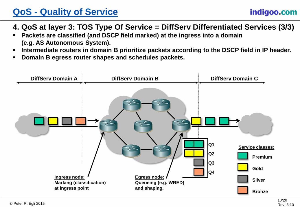
4. QoS at layer 3: TOS Type Of Service = DiffServ Differentiated Services (3/3) Packets are classified (and DSCP field marked) at the ingress into a domain
(e.g. AS Autonomous System).
Intermediate routers in domain B prioritize packets according to the DSCP field in IP header.
Domain B egress router shapes and schedules packets.
DiffServ Domain A DiffServ Domain CDiffServ Domain B
Premium
Gold
Silver
Bronze
Ingress node:
Marking (classification)
at ingress point
Egress node:
Queueing (e.g. WRED)
and shaping.
Service classes:Q1
Q2
Q3
Q4

© Peter R. Egli 201511/20
Rev. 3.10
QoS - Quality of Service indigoo.com
5. QoS at layer 3: RSVP (IntServ Integrated Services) RSVP (Resource ReSerVation Protocol) is an end-to-end protocol for bandwidth and latency
requirements allocation and reservation.
The Network must support RSVP in all hops; it is however possible to traverse non-RSVP
enabled networks (with reduced QoS guarantees).
The Network must enforce (police) misbehavior (prioritize packets over others).
RSVP does not scale well since every hop needs to support a state table for each specific
packet flow.
RSVP does not (yet) allow changing routes to achieve optimum QoS rather than optimum
path. RSVP uses standard IP routing protocols for deciding where to allocate resources.
Since RSVP uses receiver-based allocation (as opposed to sender-based allocation)
multicast can be easily supported (reservations flow towards the root of the multicast tree).
RSVP PATH message (stores path to receiver which then allocates
resources along the path).
RSVP RESV (reservation) message reserves bandwidth etc. along the path.
SenderReceiver

© Peter R. Egli 201512/20
Rev. 3.10
QoS - Quality of Service indigoo.com
6. Queueing strategies (1/2)1. FIFO - First In First Out:
No classes, no priority. Packets are sent
in the same order as they are received. This poses a problem with bursty data applications
(e.g. FTP) where long trains of packets may clog the queue and thus impair real-time traffic
(VoIP).
2. Priority queueing PQ (SP – Strict Priority Queue):
Packets of one class are transmitted before any
packet of all lower priority classes.
3. Round Robin RR:
Bandwidth is equally divided and assigned to each
competing service class.
4. Class Based queueing CB:
Same as RR, but the class queues have
unequal weights to give certain classes
more bandwidth. Also called
Weighted Round Robin (WRR).
50%
25%
13%
12%
© Peter R. Egli 201513/20
Rev. 3.10
QoS - Quality of Service indigoo.com
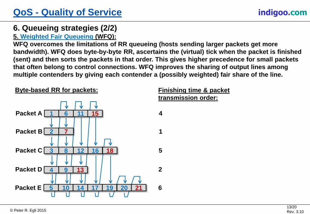
6. Queueing strategies (2/2)5. Weighted Fair Queueing (WFQ):
WFQ overcomes the limitations of RR queueing (hosts sending larger packets get more
bandwidth). WFQ does byte-by-byte RR, ascertains the (virtual) tick when the packet is finished
(sent) and then sorts the packets in that order. This gives higher precedence for small packets
that often belong to control connections. WFQ improves the sharing of output lines among
multiple contenders by giving each contender a (possibly weighted) fair share of the line.
1 6 11 15
3 8 12 16 18
4 9 13
5 10 14 17 19 20 21
2 7
Packet A
Packet B
Packet C
Packet D
Packet E
Finishing time & packet
transmission order:
4
1
5
2
6
Byte-based RR for packets:
© Peter R. Egli 201514/20
Rev. 3.10
QoS - Quality of Service indigoo.com
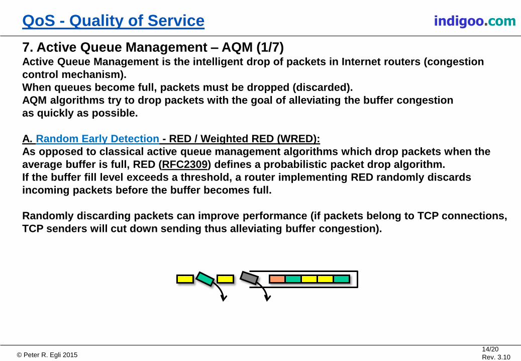
7. Active Queue Management – AQM (1/7)Active Queue Management is the intelligent drop of packets in Internet routers (congestion
control mechanism).
When queues become full, packets must be dropped (discarded).
AQM algorithms try to drop packets with the goal of alleviating the buffer congestion
as quickly as possible.
A. Random Early Detection - RED / Weighted RED (WRED):
As opposed to classical active queue management algorithms which drop packets when the
average buffer is full, RED (RFC2309) defines a probabilistic packet drop algorithm.
If the buffer fill level exceeds a threshold, a router implementing RED randomly discards
incoming packets before the buffer becomes full.
Randomly discarding packets can improve performance (if packets belong to TCP connections,
TCP senders will cut down sending thus alleviating buffer congestion).

© Peter R. Egli 201515/20
Rev. 3.10
QoS - Quality of Service indigoo.com
7. Active Queue Management – AQM (2/7)B. Explicit Congestion Notification – ECN (1/5):
ECN (RFC3168) tries to inform a sender of an impending packet drop in a router so that
the sender can throttle transmission rate to alleviate the problem before packet drop occurs.
ECN combines IP and transport layer (e.g. TCP) functionality by using bits in the IP header and
TCP header. Support for other transport protocols may be added in the future.
IP header:
ECN uses 2 bits of the DSCP field in the IP header to signal congestion information to
the receiver.
DSCPECT
(0)
ECT
(1)
ECN-capable
transport bits (ECT)DiffServ Code Point
ECT(0) ECT(1) Description
0 0 Non-ECT codepoint (packet not
using ECT)
0 1 ECT(0) codepoint
1 0 ECT(1) codepoint
1 1 Congestion experienced (CE)
codepoint
DSCP / ECT
IP header

© Peter R. Egli 201516/20
Rev. 3.10
QoS - Quality of Service indigoo.com
7. Active Queue Management – AQM (3/7)B. Explicit Congestion Notification – ECN (2/5):
TCP header:
ECN defines 2 additional flags (bits) in the TCP header which are used to signal congestion
between TCP-endpoints.
TCP Flag Description
CWR Congestion Window Reduced flag.
Informs the TCP receiver that the sender has reduced
the congestion window.
ECE ECN-Echo flag. The TCP receiver informs the TCP
sender of the reception of a an IP packet that
experienced congestion (ECN codepoint = CE).
Header Length Unused
Source Port Destination Port
Sequence Number
Acknowledgement Number
Checksum Urgent Pointer
TCP header
© Peter R. Egli 201517/20
Rev. 3.10
QoS - Quality of Service indigoo.com
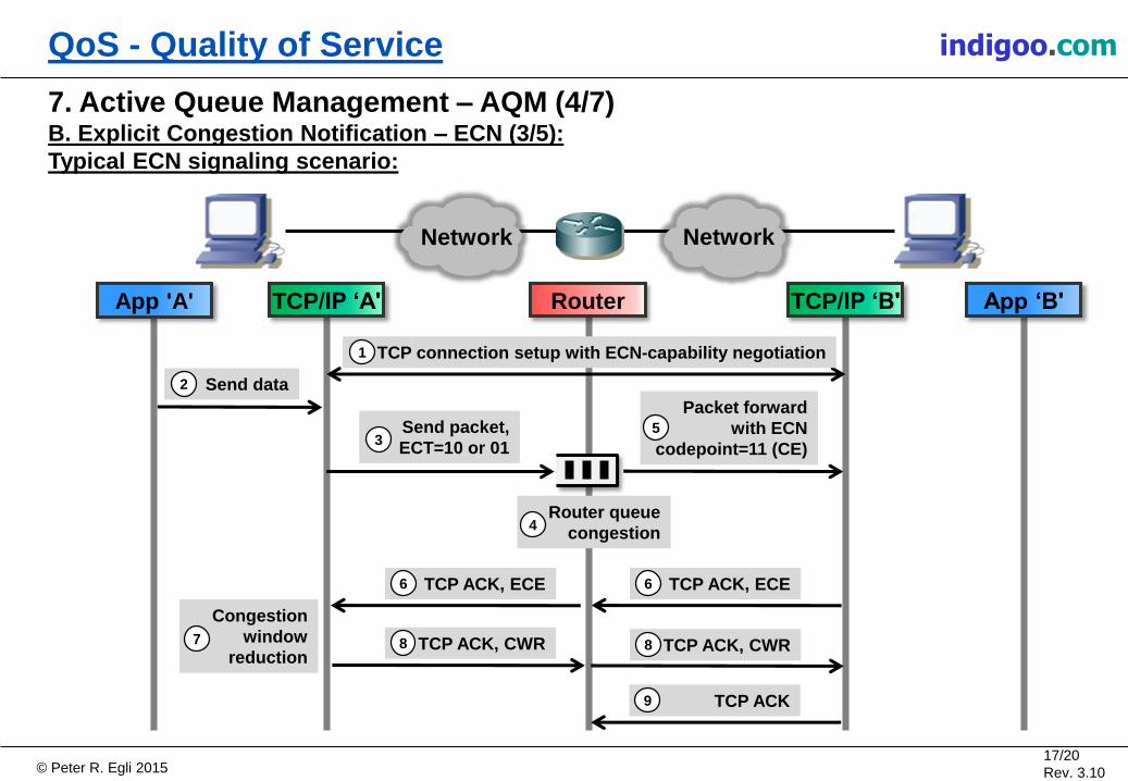
7. Active Queue Management – AQM (4/7)B. Explicit Congestion Notification – ECN (3/5):
Typical ECN signaling scenario:
App 'A' TCP/IP ‘B' App ‘B'TCP/IP ‘A' Router
TCP connection setup with ECN-capability negotiation1
Send packet,
ECT=10 or 013
Send data2
Router queue
congestion4
Packet forward
with ECN
codepoint=11 (CE)
5
Network Network
TCP ACK, ECE6TCP ACK, ECE6
TCP ACK, CWR8 TCP ACK, CWR8
Congestion
window
reduction7
TCP ACK9

© Peter R. Egli 201518/20
Rev. 3.10
QoS - Quality of Service indigoo.com
7. Active Queue Management – AQM (5/7)B. Explicit Congestion Notification – ECN (4/5):
Step by step explanation of a ECN scenario:
1. TCP connection setup:
During TCP connection setup (3-way handshake), both TCP endpoints signal their willingness and ability to
use ECN.
TCP ‘A’ sends a first segment with SYN, ECE, CWR flags set.
TCP ‘B’ responds with a segment with SYN, ACK, ECE flags set (CWR is not set). The TCP connection is now
ECN-enabled.
2. Application ‘A’ send data:
Application ‘A’ sends data over the socket interface.
3. IP packet with ECT codepoint:
Because the TCP connection is ECN-enabled, the IP layer of host ‘A’ sends packets with an ECT codepoint
(either ECT=10 or ECT=01). This signals to routers along the transmission path that these packets belong to
an ECN-enabled flow.
4.&5. Congestion in intermediate router:
A router in the transmission path experiences congestion (packet drop is imminent). The router reads the
ECT-codepoint (01 or 11) and determines that the packet belongs to an ECN-enabled connection. Instead of
dropping the packet, the router sets the
ECT codepoint to 11 (Congestion Experienced) and forwards the packet towards the receiver.
© Peter R. Egli 201519/20
Rev. 3.10
QoS - Quality of Service indigoo.com
7. Active Queue Management – AQM (6/7)B. Explicit Congestion Notification – ECN (5/5):
Step by step explanation of a ECN scenario:
6. TCP ‘B’ signals congestion back to sender:
TCP ‘B’ receives the congestion indication and signals it back to the TCP ‘A’ by setting the ECE flag in the
TCP header in an acknowledgement segment.
7. TCP ‘A’ reduction of congestion window:
TCP ‘A’ receives the ECE flag and reacts as if packet loss occurred by recucing the congestion window size
and throttling the transmission rate (see RFC2581 for TCP congestion control). If multiple TCP flows through
the congested router react this way, the congestion is likely to disappear.
8. TCP ‘A’ signaling reduction of congestion window:
TCP ‘A’ signals the reduction of the congestion window to TCP ‘B’ by sending TCP segments with the CWR
flag set.
9. TCP ‘B’ clear ECE flag:
The reception of the CWR flag signals to TCP ‘B’ that the sender has reduced the congestion window size and
thus reacted accordingly to the congestion situation.
TCP ‘B’ now clears the ECE flag in TCP segments until the next IP packet with an ECT codepoint is received.

© Peter R. Egli 201520/20
Rev. 3.10
QoS - Quality of Service indigoo.com
7. Active Queue Management – AQM (7/7)C. CoDel (Controlled Delay):
Problem with TCP:
Congestion control uses packet drops as congestion indication and to find a suitable
transmission rate.
Large buffers in routers introduce delay but prevent packet drops.
Sender TCP does not receive packet drop indication (fast retransmit) thus not reducing
transmission rate.
This in turn further fills the buffers in routers (bufferbloat).
CoDel tries preventing bufferbloat by limiting average packet delay in buffers (< 5ms).
If packet delay increases above 5ms, the packet is dropped thus signaling congestion to
TCP.
CoDel advantages over RED/WRED:
+ Parameter-less, no parameters to be set administratively.
+ Relatively simple implementation compared to RED/WRED.
+ Indipendent of round-trip-delay, link rate and other factors.