Qiuling Zhu, Eric L. Turner, Christian R. Berger, Larry Pileggi, Franz Franchetti September 22, 2011...
30
Qiuling Zhu, Eric L. Turner, Christian R. Berger, Larry Pileggi, Franz Franchetti September 22, 2011 Application-Specific Logic-in- Memory for Polar Format Synthetic Aperture Radar
-
date post
22-Dec-2015 -
Category
Documents
-
view
213 -
download
0
Transcript of Qiuling Zhu, Eric L. Turner, Christian R. Berger, Larry Pileggi, Franz Franchetti September 22, 2011...

Qiuling Zhu, Eric L. Turner, Christian R. Berger, Larry Pileggi, Franz Franchetti
September 22, 2011
Application-Specific Logic-in-Memory forPolar Format Synthetic Aperture Radar
Slide 2 Slide 2
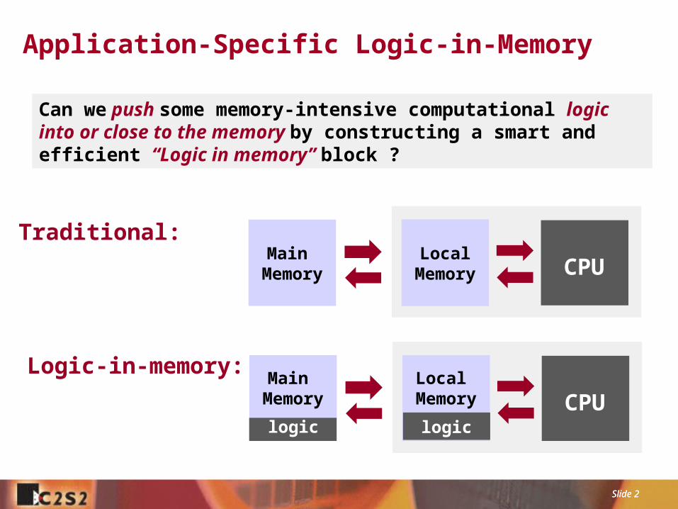
Application-Specific Logic-in-Memory
Can we push some memory-intensive computational logic into or close to the memory by constructing a smart and efficient “Logic in memory” block ?
Traditional:
CPUMain
MemoryLocal
Memory
Main Memory
logicCPU
Local Memory
logic
Logic-in-memory:

Slide 3 Slide 3
Enabling Technology: Regular Patterns
Regular patterns
Application-specific “Magic” memory
Compatible Logic
SRAM bitcell
Compatible logic cells
Implementing sub-22nm designs using a limited set of pattern constructs can enable robust compilation of smart memories
D. Morris, et. al, “Design of Embedded Memory and Logic Based On Pattern Constructs” , Symp.VLSI Technology, June 2011.

Slide 4 Slide 4
Tool Chain: Chip Generator and Memory Compiler
logic
Chip Generator
SRAM bitcell
Compatible logic cells
App-specific logic-in-memory
Smart Memory Compiler
Chip Generator Generates designs from high-level parameterization and specification Utilizes Stanford’s chip generator platform (Genesis 2)
Smart Memory Compiler Map memory and logic onto a set of pre-characterized pattern constructs Allow flexible synthesis of logic and memory functionalities in place of hard IP
Local Memory
Logic
Logic in Memory
Slide 5 Slide 5
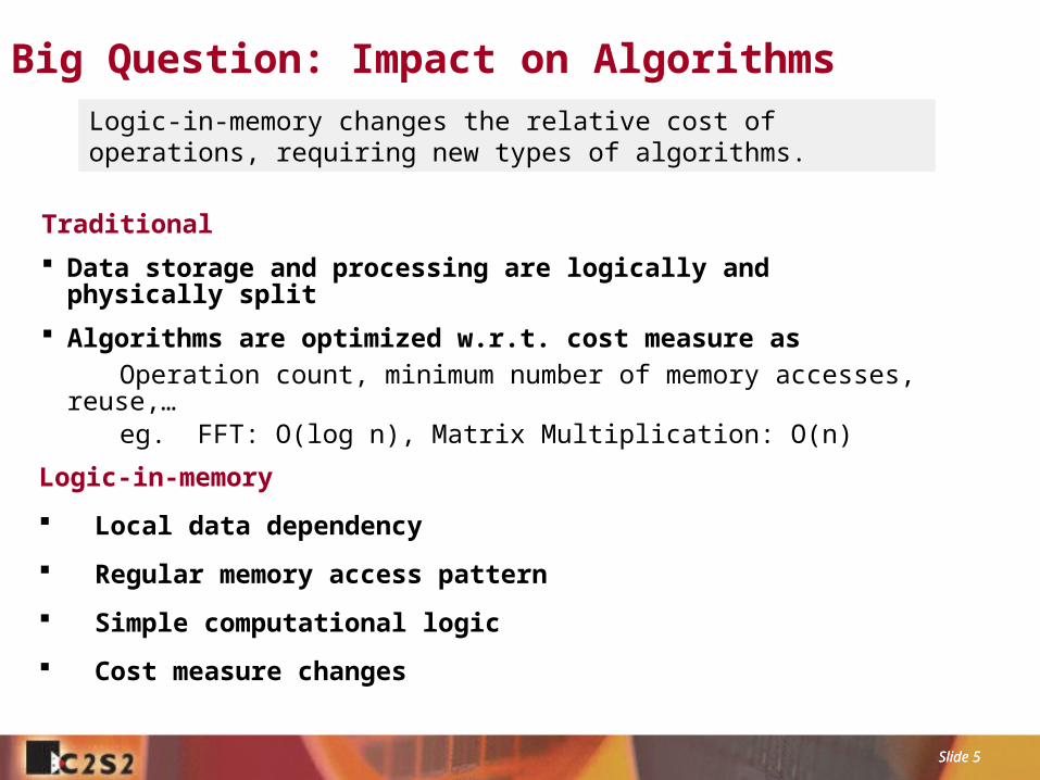
Big Question: Impact on Algorithms
Logic-in-memory
Local data dependency
Regular memory access pattern
Simple computational logic
Cost measure changes
Traditional
Data storage and processing are logically and physically split
Algorithms are optimized w.r.t. cost measure as
Operation count, minimum number of memory accesses, reuse,… eg. FFT: O(log n), Matrix Multiplication: O(n)
Logic-in-memory changes the relative cost of operations, requiring new types of algorithms.

Slide 6 Slide 6
Case Study: Interpolation Memory
ALU
ALU
Original Phantom image
x
level k
level k-1
level k-2
Ex 4: Tomography Backprojection Ex 3: Geometry Transformation
Ex 1: FFT Twiddle Factor Ex 2: Image Pyramid Memory
Slide 7 Slide 7
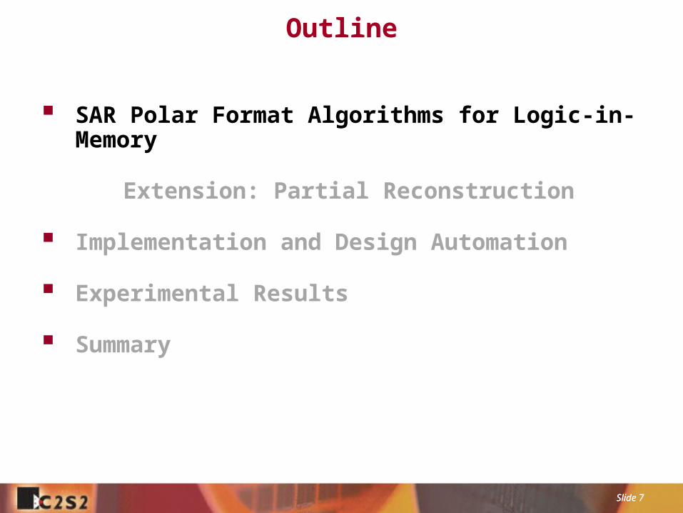
Outline
SAR Polar Format Algorithms for Logic-in-Memory
Extension: Partial Reconstruction
Implementation and Design Automation
Experimental Results
Summary

Slide 8 Slide 8
Synthetic Aperture Radar (SAR)
Data acquisition
SAR image formation
Interpolation
2D FFT
Image formation
Slide 9 Slide 9
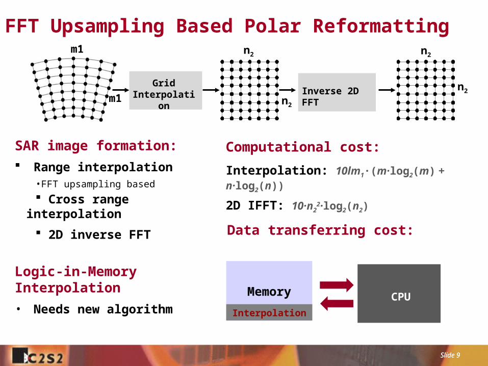
FFT Upsampling Based Polar Reformatting
GridInterpolation Inverse 2D FFT
I is the number of segments per range line, m is the input segment size and n is the size of the upsampled output segment.
Computational cost:
Interpolation: 10lm1·(m·log2(m) + n·log2(n))
2D IFFT: 10·n22·log2(n2)
SAR image formation:
Range interpolation•FFT upsampling based
Cross range interpolation
2D inverse FFT
n2
n2
m1
m1
n2
n2
Logic-in-Memory Interpolation
• Needs new algorithm
Data transferring cost:
Memory CPU
Interpolation
Slide 10 Slide 10
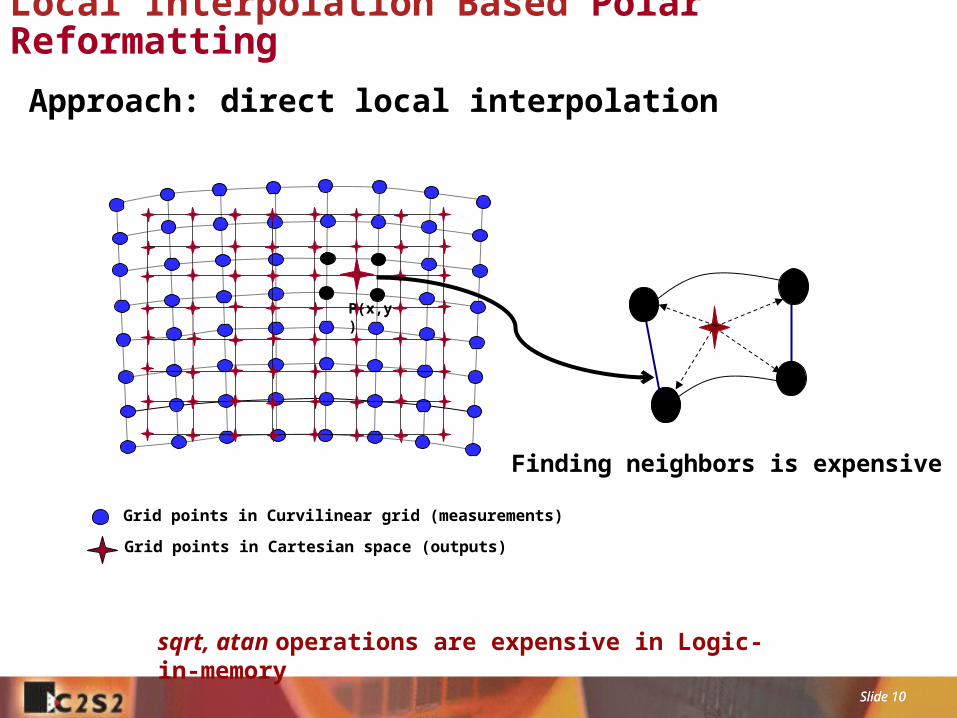
Local Interpolation Based Polar Reformatting
Grid points in Curvilinear grid (measurements)
Grid points in Cartesian space (outputs)
P(x,y)
Approach: direct local interpolation
sqrt, atan operations are expensive in Logic-in-memory
Finding neighbors is expensive
Slide 11 Slide 11
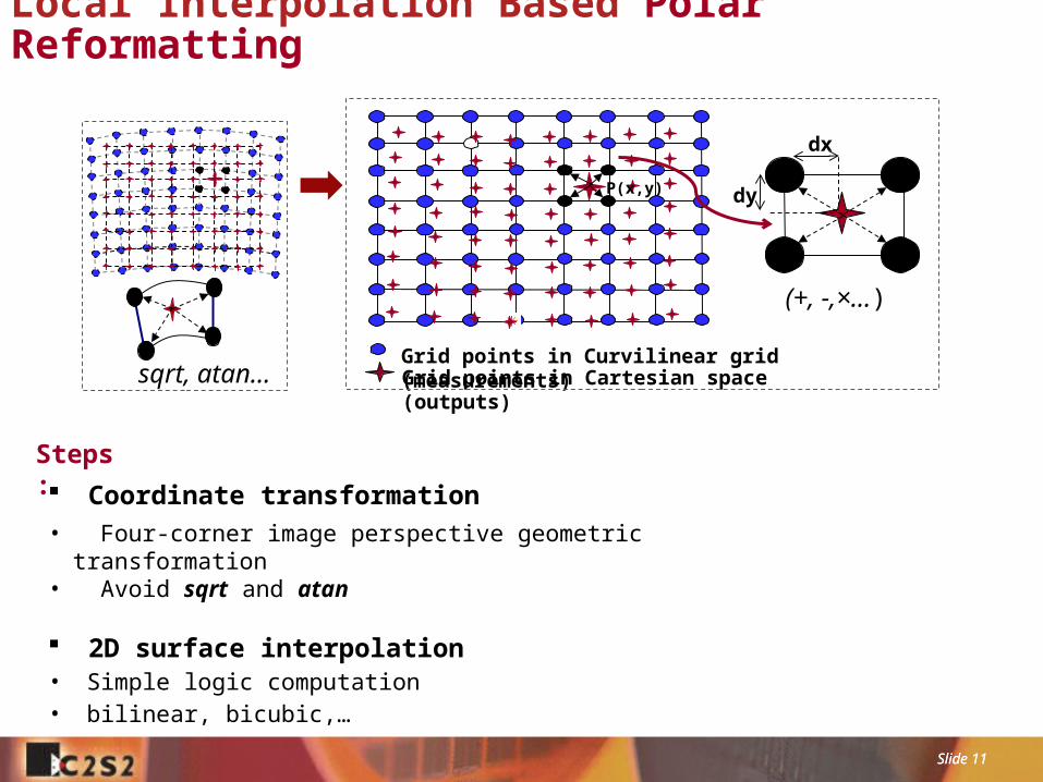
Local Interpolation Based Polar Reformatting
Coordinate transformation• Four-corner image perspective geometric transformation• Avoid sqrt and atan
2D surface interpolation• Simple logic computation• bilinear, bicubic,…
Steps:
sqrt, atan… Grid points in Curvilinear grid (measurements)Grid points in Cartesian space (outputs)
P(x,y)
(+, -,×…)
dx
dy

Slide 12 Slide 12
2D Interpolationdx
i, j i, j+1
i+1, ji+1, j+1
dy P(x,y)
Bilinear Interpolation
i-1, j-1 i-1, j i-1, j+1 i-1, j+2
i, j-1 i, j i, j+1 i, j+2
i+1, j-1 i+1, j i+1, j+1 i+1, j+2
i+2, j-1 i+2, j i+2, j+1 i+2, j+2
dx
dy
P(x,y)
Bicubic Interpolation
Nearest Neighbor
i, j
Dividable 2D interpolation• Bilinear: (2 horizontal + 1 vertical) 1D interpolations
• Bicubic: (4 horizontal + 1 vertical) 1D interpolations
• 1D interpolation: Newton divided difference form based polynomial interpolation
Suitable for Logic in Memory• Localized computation: Outputs are only decided by their neighbors
• Regular memory access: Continuous or block data array access
• Simple computational logic: Adders, subs, boolean operations …

Slide 13 Slide 13
Tiling: Accurate Geometry Approximation
Tile1 Tile2
Tile3 Tile4
Geometry approximation conditions: deltawidth is small enough RL is large enough
RL
deltawidth
K
Solution: Image tiling
error
Tile in the Cartesian grid Output oriented tiling Easy to identify boundary and tile overlap

Slide 14 Slide 14
Outline
SAR Polar Format Algorithms for Logic-in-Memory
Extension: Partial Reconstruction
Implementation and Design Automation
Experimental Results
Summary
Slide 15 Slide 15
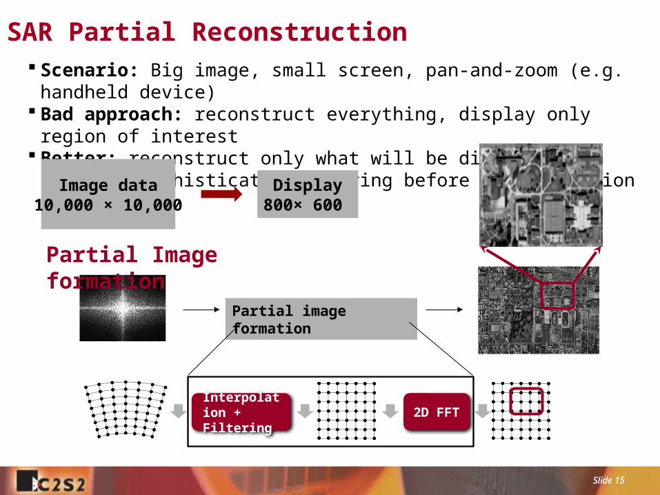
SAR Partial Reconstruction Scenario: Big image, small screen, pan-and-zoom (e.g. handheld device) Bad approach: reconstruct everything, display only region of interest Better: reconstruct only what will be displayed
requires sophisticated filtering before reconstruction
Image data10,000 × 10,000
Display800× 600
Partial image formation
Interpolation + Filtering
2D FFT
Partial Image formation

Slide 16 Slide 16
Partial Reconstruction I
Reconstructs and displays low-resolution full-size image
• Traditional: Interpolate all, full-size large IFFT then decimation• Alternative: Partial interpolation then smaller-size IFFT• Theory behind: Multiplication in the Frequency is identical to convolution in the spatial space.
Low pass filtering In the spatial domain
cut off high frequencies in Fourier space
only computes the pixels that are required!
Smaller-size interpolation
Smaller-size IFFT

Slide 17 Slide 17
Partial Reconstruction IIReconstructs and displays a high-resolution image portion
• Traditional: Full-size large IFFT, reconstruct all then cut off unnecessary region• Alternative: Decimation filtering and then smaller-size IFFT• Theory behind: Multiplication in the space is identical to convolution in the Fourier domain. Displacement in time is equivalent to phase shift
smaller IFFT
FFT sample
interpolatedecimation
filter
ROI
Logic inMemory
Slide 18 Slide 18
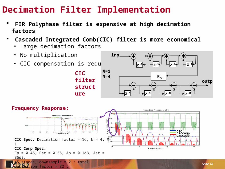
Decimation Filter Implementation
0 5 10 15
-120
-100
-80
-60
-40
-20
0
Frequency (Hz)
Ma
gn
itu
de
(d
B)
Magnitude Response (dB)
ciccompCICcascade
CIC Spec: Decimation factor = 16; N = 4; M= 1 CIC Comp Spec: Fp = 0.45; Fst = 0.55; Ap = 0.1dB, Ast = 35dB; 45 stages; downsample = 2 ; total decimation factor = 32 ;
Frequency Response:
FIR Polyphase filter is expensive at high decimation factors Cascaded Integrated Comb(CIC) filter is more economical
• Large decimation factors
• No multiplication
• CIC compensation is required z-1 z-1 z-1 z-1
R
z-M z-M z-M z-M
inp
outp
M=1N=4
CIC filter structure
Slide 19 Slide 19
Outline
SAR Polar Format Algorithms for Logic-in-Memory
Extension: Partial Reconstruction
Implementation and Design Automation
Experimental Results
Summary
Slide 20 Slide 20
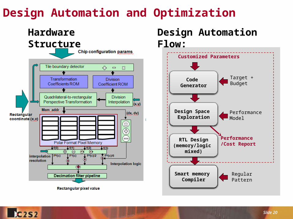
Design Automation and Optimization
Customized Parameters
Target + Budget
Performance Model
Performance/Cost Report
Regular Pattern
Smart memory Compiler
RTL Design(memory/logic
mixed)
Design Space Exploration
Code Generator
Hardware Structure Design Automation Flow:

Slide 21 Slide 21
Chip Generator
http://genesis.web.ece.cmu.edu/gui/scratch/mydesign-10545.php
Reference: O. Shacham, O. Azizi, M. Wachs, et. al, "Rethinking Digital Design: Why Design Must Change”, Micro, IEEE, Dec 2010.
Slide 22 Slide 22
Outline
SAR Polar Format Algorithms for Logic-in-Memory
Extension: Partial Reconstruction
Implementation and Design Automation
Experimental Results
Summary
Slide 23 Slide 23
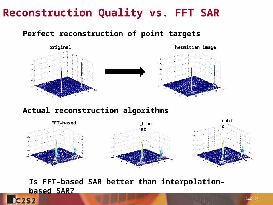
original
linearcubic
hermitian image
FFT-based
Actual reconstruction algorithms
Is FFT-based SAR better than interpolation-based SAR?
Perfect reconstruction of point targets
Reconstruction Quality vs. FFT SAR
Slide 24 Slide 24
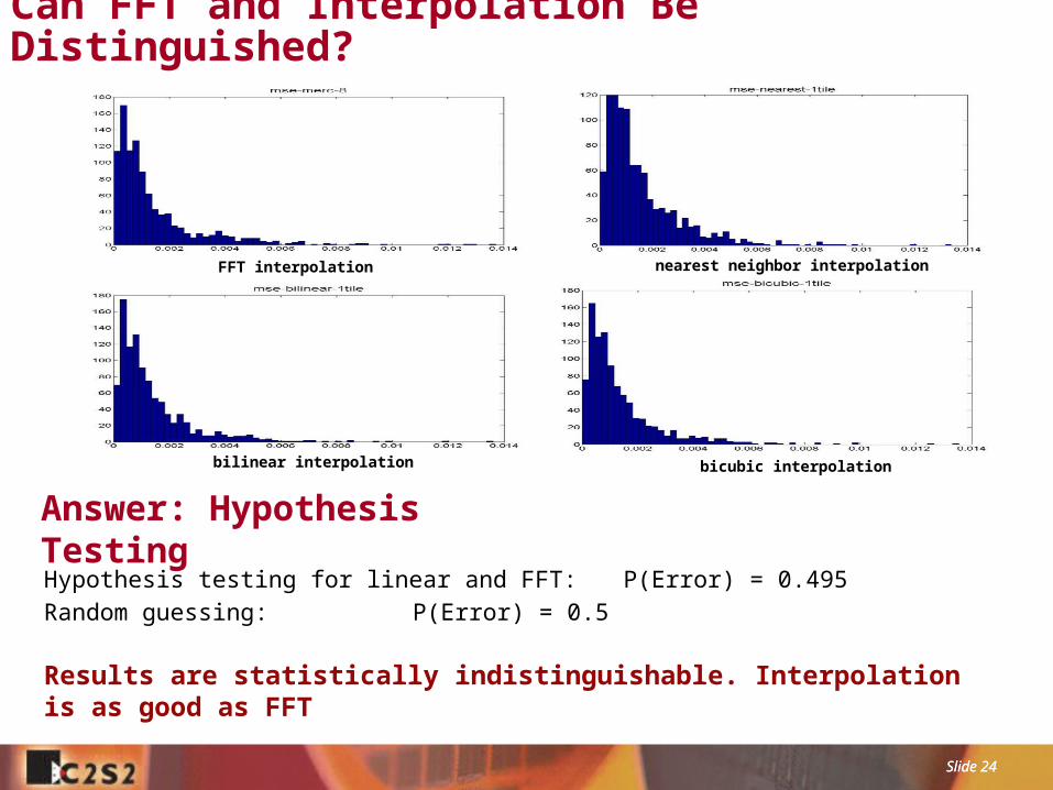
Can FFT and Interpolation Be Distinguished?
Answer: Hypothesis TestingHypothesis testing for linear and FFT: P(Error) = 0.495
Random guessing: P(Error) = 0.5
Results are statistically indistinguishable. Interpolation is as good as FFT
bilinear interpolation
FFT interpolation nearest neighbor interpolation
bicubic interpolation

Slide 25 Slide 25
Accuracy Improvement Through Tiling
00.0020.0040.0060.008
0.010.0120.0140.0160.018
0.02
Mean Square Error relative to Gold Standard Method
One-tile
4-tiles
16-tiles
Nearest Neighbor Bilinear Bicubic
Mean square error vs. interpolation methods for different tile numbers
MSE decreases with more tiling and higher interpolation order

Slide 26 Slide 26
Energy Saving for Logic-in-Memory
Energy saving increases with the increasing of problem size
1.00E+00
1.00E+01
1.00E+02
1.00E+03
1.00E+04
1.00E+05
1.00E+06
1.00E+07
1.00E+08
1.00E+09
1.00E+10
1.00E+11
1.00E+12
size32×32 size64×64 size128×128 size256×256 size512×512
Energy Saving for SAR PFA Grid Interpolation
CPU_centricLogic_in_Memory
Energy(nJ) vs. SAR image size

Slide 27 Slide 27
Accurate Region-of-Interest by Sacrificing Border
0
1
2
3
4
5
6
7
8
9
0.5 0.55 0.6 0.65 0.7 0.75 0.8 0.85 0.9 0.95 1
Decimation Filter Hardware Cost with ROI Factors
ast=15dB
ast=20ddB
ast=25dB
ast=30dB
ast=35dB
Area[1000um2]vs. Region of Interest(ROI) , decimation factor = 2
error
Imperfect image edge is resulting from non-steep filter transition region
ast: decimation filter stopband attenuation (dB)

Slide 28 Slide 28
Partial Reconstruction: Operation saving vs. Cost
IFFT operation counts decreases exponential with increasing decimation factors Logic hardware cost is negligible compared with memory cost Decimation filter cost slightly increases when increasing decimation factors
0.00E+00
5.00E-05
1.00E-04
1.50E-04
2.00E-04
2.50E-04
3.00E-04
3.50E-04
4.00E-04
0 20 40 60 80 100 120 140
Logic in Memory Hardware Cost
Grid Interpolation + Decimation Filter(Beta=0.3,Ast=25dB)Grid Interpolation + Decimation Filter(Beta=0.3,Ast=35dB)Grid Interpolation + Decimation Filter(Beta=0.2, Ast=35dB)Grid Interpolation
Logic area/memory area vs. decimation factor
1.00E+04
1.00E+05
1.00E+06
1.00E+07
1.00E+08
1.00E+09
1.00E+10
0 20 40 60 80 100 120 140
2D IFFT Computational Cost vs Decimation FactorOperation count vs. decimation factor, SAR image size = 4K×4K
Beta: filter rolloff factors ; Ast: decimation filter stopband attenuation (dB)

Slide 29 Slide 29
Outline
SAR Polar Format Algorithms For Logic-in-Memory
Extension: Partial Reconstruction
Implementation and Design Automation
Experimental Results
Summary
Slide 30 Slide 30
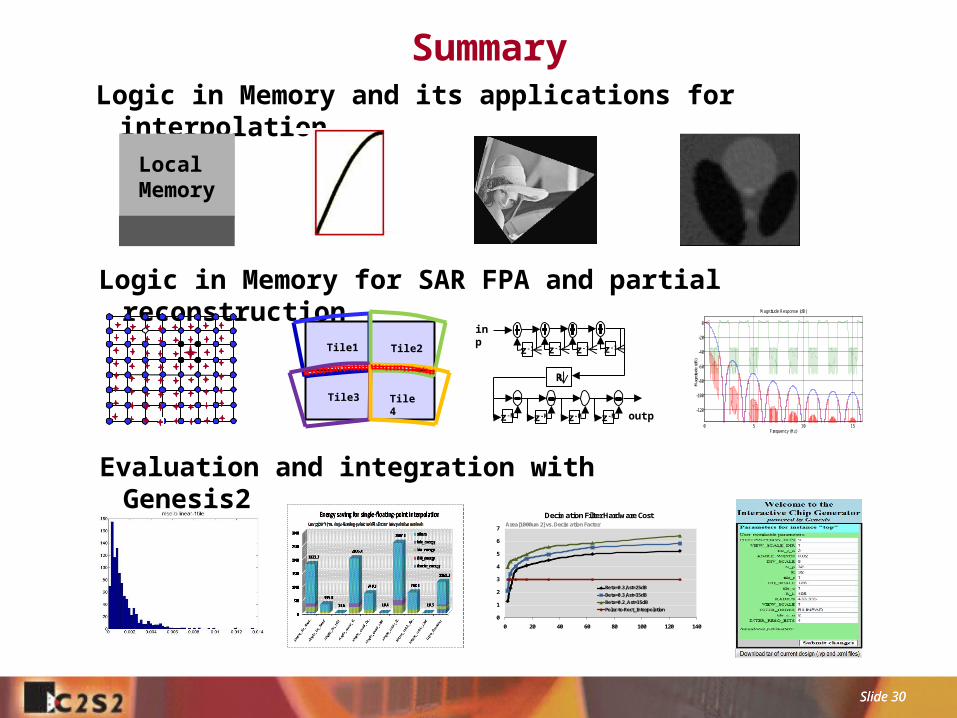
SummaryLogic in Memory and its applications for interpolation
Evaluation and integration with Genesis2
Logic in Memory for SAR FPA and partial reconstruction
Tile1 Tile2
Tile3 Tile4
0 5 10 15
-120
-100
-80
-60
-40
-20
0
Frequency (Hz)
Mag
nitu
de (d
B)
Magnitude Response (dB)
z-1 z-1 z-1 z-1
R
z-M z-M z-M z-M
inp
outp
0
1
2
3
4
5
6
7
0 20 40 60 80 100 120 140
Decimation Filter Hardware Cost
Beta=0.3,Ast=25dBBeta=0.3,Ast=35dBBeta=0.2, Ast=35dBPolar-to-Rect_Interpolation
Area[1000um2] vs. Decimation Factor
Local Memory