QForm 2007 March - Strona główna...
116
Q Q QForm Form Form Form3D 3D 3D 3D Advanced software for forging simulation
Transcript of QForm 2007 March - Strona główna...

QQQQFormFormFormForm3D3D3D3D
Advanced software for forging simulation

The goals of forging technology :
•Make the parts of the required shape
•Provide required properties
•Do it in time and at the lowest cost
Forging process is a very complicated phenomenon,
Thus even the forger with the years of experience …
still require expensive forging trials
for each new part to develope

The help can be found
in use of advanced simulation tool like QForm3D

QForm3D is
•Precise,
•Affordable
•Very simple in use
QForm3D is created for forges
And to be used by the forgers

Case study: Large 6 Cylinder CrankshaftCase study: Large 6 Cylinder CrankshaftCase study: Large 6 Cylinder CrankshaftCase study: Large 6 Cylinder Crankshaft
Simulation Inputs:
ProEngineer 6 Cylinder Crankshaft Stepped Dies Models
Billet 133mm Square, 1040mm Long
Micro Alloy Steel at 1280°C
9000T Press
The task - to predict
Press Capability
Die Filling
Material Flow
Forging Defects


QForm window ready for new problemQForm window ready for new problemQForm window ready for new problemQForm window ready for new problem

Data preparation WizardData preparation WizardData preparation WizardData preparation Wizard

Simulation: Action 1 – Mould

Simulation: Action 2 – Finish

Accurately Predicted Final Flash Thickness and Flash Widths

The temperature distributionThe temperature distributionThe temperature distributionThe temperature distribution

Look inside: the flow lines create the internal structureLook inside: the flow lines create the internal structureLook inside: the flow lines create the internal structureLook inside: the flow lines create the internal structure

One layer of the flow linesOne layer of the flow linesOne layer of the flow linesOne layer of the flow lines

Analyze the grain flow layer by layerAnalyze the grain flow layer by layerAnalyze the grain flow layer by layerAnalyze the grain flow layer by layer

Analyze the grain flow layer by layerAnalyze the grain flow layer by layerAnalyze the grain flow layer by layerAnalyze the grain flow layer by layer

Analyze the grain flow layer by layerAnalyze the grain flow layer by layerAnalyze the grain flow layer by layerAnalyze the grain flow layer by layer

Analyze the grain flow layer by layerAnalyze the grain flow layer by layerAnalyze the grain flow layer by layerAnalyze the grain flow layer by layer

The evolution of the grain flow in certain locationThe evolution of the grain flow in certain locationThe evolution of the grain flow in certain locationThe evolution of the grain flow in certain location

The lap formed on the webThe lap formed on the webThe lap formed on the webThe lap formed on the web
The lap

What is required for the simulationWhat is required for the simulationWhat is required for the simulationWhat is required for the simulation
equipmentSIMULATION
die+billet
shapes
materials
data
lubricantsprocess
parameters

Material & Lubricant: comprehensive Database
QForm database contains flow stress for more than 430 steels,
30 copper alloys, 50 aluminum alloys,
20 titanium alloys, many nickel based alloys etc.
ExampleExampleExampleExampleExampleExampleExampleExample::::::::
Flow stress depending Flow stress depending Flow stress depending Flow stress depending Flow stress depending Flow stress depending Flow stress depending Flow stress depending on strain, strainon strain, strainon strain, strainon strain, strainon strain, strainon strain, strainon strain, strainon strain, strain--------rate rate rate rate rate rate rate rate and temperatureand temperatureand temperatureand temperatureand temperatureand temperatureand temperatureand temperature
Next >>Next >>Next >>Next >>

Every user receives the
customized material and lubricant database
according to his specification

What is required for the simulationWhat is required for the simulationWhat is required for the simulationWhat is required for the simulation
equipmentSIMULATION
die+billet
shapes
materials
data
lubricantsprocess
parameters

Simulation can be performed for any type of equipment
Example: Kinematics of the Example: Kinematics of the Example: Kinematics of the Example: Kinematics of the Example: Kinematics of the Example: Kinematics of the Example: Kinematics of the Example: Kinematics of the
mechanical press with a holdermechanical press with a holdermechanical press with a holdermechanical press with a holdermechanical press with a holdermechanical press with a holdermechanical press with a holdermechanical press with a holder

For every type of equipment the simulation
gives you vital information:
Critical load Critical load Critical load Critical load Critical load Critical load Critical load Critical load
estimationestimationestimationestimationestimationestimationestimationestimation
Required numberRequired numberRequired numberRequired numberRequired numberRequired numberRequired numberRequired number
of blowsof blowsof blowsof blowsof blowsof blowsof blowsof blows
Energy and loadEnergy and loadEnergy and loadEnergy and loadEnergy and loadEnergy and loadEnergy and loadEnergy and load
requirementsrequirementsrequirementsrequirementsrequirementsrequirementsrequirementsrequirementsOptimal processOptimal processOptimal processOptimal processOptimal processOptimal processOptimal processOptimal process
parameter for safeparameter for safeparameter for safeparameter for safeparameter for safeparameter for safeparameter for safeparameter for safe
use of pressuse of pressuse of pressuse of pressuse of pressuse of pressuse of pressuse of press

What is required for the simulationWhat is required for the simulationWhat is required for the simulationWhat is required for the simulation
equipmentSIMULATION
die+billet
shapes
materials
data
lubricantsprocess
parameters

Error of the
surface
approximation
Linear (left) and quadratic (right) FE approximation
of the surface with the same number of nodes
Quadratic approximation provides accurate solution for 2D
As in QForm 2D

Accurate representation of the 3D source geometry
As in QForm 3D

How simulation runsHow simulation runsHow simulation runsHow simulation runs?

Automatic Automatic Automatic Automatic
generation of generation of generation of generation of
the meshthe meshthe meshthe mesh
Piston forging:Piston forging:Piston forging:Piston forging:
QForm makes optimal meshes in 2D and 3D without user`s interference

The models with up to 100 000 nodes runs on a The models with up to 100 000 nodes runs on a The models with up to 100 000 nodes runs on a The models with up to 100 000 nodes runs on a PCPCPCPC
with single, dual or two double core processors in parallel modwith single, dual or two double core processors in parallel modwith single, dual or two double core processors in parallel modwith single, dual or two double core processors in parallel modeeee

Practice of forging simulationPractice of forging simulationPractice of forging simulationPractice of forging simulation

Hot closed die forging: the project, the cases, the actionsHot closed die forging: the project, the cases, the actionsHot closed die forging: the project, the cases, the actionsHot closed die forging: the project, the cases, the actions
Next >>Next >>Next >>Next >>

Next >>Next >>Next >>Next >>
Hot closed die forging: the project, the cases, the actionsHot closed die forging: the project, the cases, the actionsHot closed die forging: the project, the cases, the actionsHot closed die forging: the project, the cases, the actions

Next >>Next >>Next >>Next >>
Hot closed die forging: the project, the cases, the actionsHot closed die forging: the project, the cases, the actionsHot closed die forging: the project, the cases, the actionsHot closed die forging: the project, the cases, the actions

Hot closed die forging: quick feedbackHot closed die forging: quick feedbackHot closed die forging: quick feedbackHot closed die forging: quick feedback

Simulation project
Case 1
Action 1
Case 2 Case 3
Action 2
Action 3
Action 1
Action 2
Action 3
Action 1
Action 2
Action 3
The project, the cases, the actionsThe project, the cases, the actionsThe project, the cases, the actionsThe project, the cases, the actions

Simulation project
PC 1 PC 2 PC 3
Splitting the project for parallel simulation on several PCs inSplitting the project for parallel simulation on several PCs inSplitting the project for parallel simulation on several PCs inSplitting the project for parallel simulation on several PCs in a networka networka networka network

Simulation of preforming operationsSimulation of preforming operationsSimulation of preforming operationsSimulation of preforming operations

Programmed simulation of cogging operation in a single actionProgrammed simulation of cogging operation in a single actionProgrammed simulation of cogging operation in a single actionProgrammed simulation of cogging operation in a single action

Simulation of reducer rollingSimulation of reducer rollingSimulation of reducer rollingSimulation of reducer rolling

Simulation of reducer rollingSimulation of reducer rollingSimulation of reducer rollingSimulation of reducer rolling

Scheme of electric upsetting process
U
Load
Velocity
Voltage
Simulation of electric upsettingSimulation of electric upsettingSimulation of electric upsettingSimulation of electric upsetting

Specific data required for electric upsetting simulation

Electric upsetting simulation
Electric
Upsetting

Forging of the shaft in a screw press
Closed die
Forging

• Piercing the holes and Piercing the holes and Piercing the holes and Piercing the holes and
trimming the flash by trimming the flash by trimming the flash by trimming the flash by
clipping contourclipping contourclipping contourclipping contour
Next >>Next >>Next >>Next >>
Intermediate operations to be simulated:

• Piercing the hole by Piercing the hole by Piercing the hole by Piercing the hole by
the punchthe punchthe punchthe punch
Next >>Next >>Next >>Next >>
Intermediate operations to be simulated:
Control of the dimensions
after piercing

• Piercing the holes and
trimming the flash
• Cooling in airCooling in airCooling in airCooling in air
• Cooling in tool
• Rotation and gravitational
positioning
Next >>Next >>Next >>Next >>
Intermediate operations to be simulated:

• Piercing the holes and
trimming the flash
• Cooling in air
• Cooling in toolCooling in toolCooling in toolCooling in tool
• Rotation and gravitational
positioning
Next >>Next >>Next >>Next >>
Intermediate operations to be simulated:

• Piercing the holes and
trimming the flash
• Cooling in air
• Cooling in tool
• Rotation and Rotation and Rotation and Rotation and
gravitational positioninggravitational positioninggravitational positioninggravitational positioning
Next >>Next >>Next >>Next >>
Intermediate operations to be simulated:

What benefits do
we get from
simulation?

1.1.1.1. Die filling analysisDie filling analysisDie filling analysisDie filling analysis
2. Saving the material
3. Prediction of material flow defects
4. 3-tools-simulation
5. Simulation of multi-stroke forging
6. Positioning and gravity
Solving technological problems
Next >>Next >>Next >>Next >>

Forging simulation (the die filling is shown)
Making 5 pieces of
equal high quality at a
time

Forging simulation (the die filling is shown)

1. Filling the dies at lower load
2.2.2.2. Saving the materialSaving the materialSaving the materialSaving the material
3. Prediction of material flow defects
4. 3-tools-simulation
5. Simulation of multi-stroke forging
6. Positioning and gravity
Next >>Next >>Next >>Next >>
Saving the material

Initial preform shape
Next >>Next >>Next >>Next >>

Initial preform shape
Next >>Next >>Next >>Next >>

Optimized preform shape
Next >>Next >>Next >>Next >>

Optimized preform shape
Next >>Next >>Next >>Next >>

Material saving: billet weight reduced by 12%
Optimized preform shapeInitial preform shape

Distance 35 mm in front of center line in 3rd pass

Crankshaft forging simulation (the first blow, temperature shown)

The second forging blow (strain distribution)
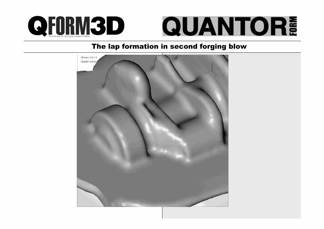
The lap formation in second forging blow

1. Filling the dies at lower load
2. Saving the material
3.3.3.3. Prediction of material flow defectsPrediction of material flow defectsPrediction of material flow defectsPrediction of material flow defects
4. 3-tools-simulation
5. Simulation of multi-stroke forging
6. Positioning and gravity
Part 2. Solving technological problems using QQQQFORMFORMFORMFORM3D3D3D3D

Identification of the laps in simulation in QForm2D
Prediction of material flow defects

The lap
Identification of the laps in simulation in QForm3D

Finding the solution by means of simulation

No lap after the die
modification
Finding the solution by means of simulation

Detecting
the laps
in 3D
simulation
Identification of the laps in simulation

Detecting
the laps
in 3D
simulation
(crosscut
view)
Identification of the laps in simulation

Precise shape
prediction and location
of possible defects
Identification of the laps in simulation

The simulation shows
exact location of the
defects
Identification of the laps in simulation

The flow-through defect is detected
by means of special “under-surface”
flow lines
Prediction of the flow-through defect by means of simulation in QForm2D

Prediction of the flow-through defect by means of simulation in QForm2D

Initial die design
Modified die design
Flow-through defect
The forged part without flow-through defect
Prediction of the flow-through defect by means of simulation in QForm2D

Photo with
defect
QForm2D
QForm3D
Prediction of the flow-through defect by means of simulation in 3D

Instability in forging

Multiple tools setsMultiple tools setsMultiple tools setsMultiple tools sets
Next >>Next >>Next >>Next >>

Conventional forging with flash

25-35% material saving
Flashless forging

1. Filling the dies at lower load
2. Saving the material
3. Prediction of material flow defects
4. 3-tools-simulation
5. Positioning and gravity
Solving technological problems using QQQQFORMFORMFORMFORM3D3D3D3D

Third blow – closed die – defect is detected

4th blow – closed die – defect is still in the critical area

Increasing the die lifeIncreasing the die life

Die stress in solid die block
Next >>Next >>Next >>Next >>

• Simulated in
Half Section on
QForm
Gear forging simulation

• 23 Toothed Gear with Finish-
Forged Teeth for Combined
Harvester PTO Application
• Dies Cracking After Around
400 Parts
• Improvement Needed for
Production Quantities
Die crack

• Maximum Stress
Shown Where Dies
Were Cracking
Die stress in solid die block

• “Inserted” Die Now Machined
• To Trial on Next Production
Batch
• Potential Improvement in Die Life: At Least 150%
• Potential Cost Saving: ~£2000 (approx 4 dies)
Split die instead of solid die block

Pre-stressed dies with
inserts and pegs
Complex die assemblies
Next >>Next >>Next >>Next >>

Next >>Next >>Next >>Next >>
Effective stress distribution in assembled dieEffective stress distribution in assembled dieEffective stress distribution in assembled dieEffective stress distribution in assembled die

Shrink ring for the dies in 3DShrink ring for the dies in 3DShrink ring for the dies in 3DShrink ring for the dies in 3D

The effect of shrink fitting for the diesThe effect of shrink fitting for the diesThe effect of shrink fitting for the diesThe effect of shrink fitting for the dies
Effective stress distribution with free lateral surface Effective stress distribution with shrink fitting

Die wear predictionDie wear predictionDie wear predictionDie wear prediction

Die wear predictionDie wear predictionDie wear predictionDie wear prediction
Die wear depends on:
•Contact traction
•Relative sliding velocity on a die surface
•Yield stress of the die material
•Time of the contact

Die wear prediction: relative die wear factor distribution

1Comparing the results of the predicted die wear distribution with the experiment
The experimental results of the die wear evaluation are obtained by Dr. Jan Cermak, Czech Technical University in Prague
a. b.
The conditions of the experiment: round bar 13mm,
steel AISI 1030, temperature 1100-1150 degrees C

1
0
0,05
0,1
0,15
0,2
0,25
0,3
0 250 500 1000 1500 1900
Number of parts
De
pth
of
the
die
we
ar
The maximum depth of the die wear (mm) versus the
number of the forged parts (the upper die)
The experimental evaluation of the abrasive wear

1
Maximum
wear area
Experimental measurement after:
1 (1), 500 (2), 1000 (3), 1500 (4) and 1900 (5) parts.
Abrasive wear distribution *10-1 mm of the upper die
Simulation results

1
Maximum wear
area
Experimental measurement after:
1 (1), 500 (2), 1000 (3), 1500 (4) and 1900 (5) parts.
Simulation results
Abrasive wear distribution *10-1 mm of the lower die

1st action 2nd action
3rd action Trimming
3 Initial technology of cold forging of the bolt

3 Initial technology of cold forging of the bolt
Intensive sliding of forged
material under the upper die at
the 3rd action of the initial
technology

3 Relative die wear maximum values
20.78
2.8
maximum die wear wr=20.78 exactly on the edge
of the upper die;

1st action2nd action
Trimming
4 Modified technology of cold forging of the bolt

Velocity vectors and the effective strain
Filling of the die cavity for
modified technology (b)
with equal sliding of the
material along upper and
lower dies.
5

Maximum relative die wear wr =9.90 on the lower die
7.28
9.90
6 Modified technology of cold forging of the bolt

thethethethe stages stages stages stages of forgingof forgingof forgingof forging
Elastic deflection of the dies and its compensation
Deflection of the die (magnified)

Graphs of upper die surface deflection along the radius of the forged
part for initial and profiled die shape
Deflection of forged part surface
0
0,02
0,04
0,06
0,08
0,1
0,12
0,14
0,16
0,18
0,2
1 2 3 4 5 6 7 8 9 10 11 12
Points along the radius
De
via
tio
n[m
m]
Initial die
Profiled die
Tolerance
Elastic deflection of the dies and its compensation

Export of deformed and profiled shapes of the tools
Elastic deflection of the dies and its compensation

The blocker die surface deflection (magnification factor 100)
Compensation of the elastic deformation of the dies
Export of
profiled die
shape to CAD
for precise
forging

QQQQForm is very economically efficientForm is very economically efficientForm is very economically efficientForm is very economically efficient
•It is the perfect tool for die designer and
forging engineer that they use in their
everyday practice
•It saves material, tools, energy
•The development is fast and effective, no
forging trials required for new jobs
•Then using QForm the forging skill is
significantly improving

The forger with QForm
is skilled and professional
The forging company with QForm
is successful