qcs 2010 Part 11 Sewer Rehabilitation
26
B U R H A N I N T E R N A T I O N A L QCS 2010 Section 8 Part 11 Sewer Rehabilitation Page 1 QCS 2010 11. SEWER REHABILITATION ......................................................................... 3 11.1 GENERAL ...................................................................................................... 3 11.1.1 Scope 3 11.1.2 References 3 11.1.3 Definitions 4 11.1.4 Submittals 5 11.1.5 Quality Assurance 6 11.1.6 Warranty 7 11.2 GENERAL REQUIREMENTS ........................................................................ 7 11.2.1 Work Programme Review, Cleaning, Inspection 7 11.2.2 Safety 7 11.2.3 Preparation for Installation of Linings 7 11.3 SEALING OF PIPES AND MANHOLES ........................................................ 9 11.3.1 Scope 9 11.3.2 Sealing Compounds 9 11.3.3 Joint Sealing of Pipes 10 11.3.4 Sealing of Manholes 11 11.4 SLIPLINING OF SEWERS .......................................................................... 11 11.4.1 General 11 11.4.2 Materials 12 11.4.3 Installation of Sliplining 12 11.5 DEFORMED PIPE LINER INSTALLATION ................................................. 14 11.5.1 Scope 14 11.5.2 Materials 14 11.5.3 Installation 15 11.6 CURED-IN-PLACE LINER INSTALLATION (INVERSION METHOD) ......... 16 11.6.1 Scope 16 11.6.2 Materials 17 11.6.3 Installation of Cured-In-Place Liner 17 11.7 SPIRAL WOUND PROFILE LINER ............................................................. 19 11.7.1 Scope 19 11.7.2 Materials 19 11.7.3 Installation of Spiral Wound Profile Liner 20 11.8 PIPE CRACKING OR BURSTING ............................................................... 21 11.8.1 Scope 21 11.8.2 General 21 11.8.3 Materials 21 11.8.4 Installation Equipment 21 11.8.5 Installation 22
-
Upload
rotsapnayrb -
Category
Documents
-
view
222 -
download
0
Transcript of qcs 2010 Part 11 Sewer Rehabilitation

8/10/2019 qcs 2010 Part 11 Sewer Rehabilitation
http://slidepdf.com/reader/full/qcs-2010-part-11-sewer-rehabilitation 1/26
B U R H A N I N T
E R N A T I ON A L
QCS 2010 Section 8 Part 11 Sewer Rehabilitation Page 1
QCS 2010
11. SEWER REHABILITATION ............ ............. ............. ............. ............. ......... 3
11.1 GENERAL ............. ............. ............. ............. ............. ............. ............. ........... 3
11.1.1 Scope 3
11.1.2 References 311.1.3 Definitions 411.1.4 Submittals 511.1.5 Quality Assurance 611.1.6 Warranty 7
11.2 GENERAL REQUIREMENTS ............. ............. ............. .............. ............ ....... 7
11.2.1 Work Programme Review, Cleaning, Inspection 711.2.2 Safety 711.2.3 Preparation for Installation of Linings 7
11.3 SEALING OF PIPES AND MANHOLES ............ .............. ............. ............. .... 9
11.3.1 Scope 911.3.2 Sealing Compounds 911.3.3 Joint Sealing of Pipes 1011.3.4 Sealing of Manholes 11
11.4 SLIPLINING OF SEWERS ............. ............. ............. ............. ............. ......... 11
11.4.1 General 1111.4.2 Materials 1211.4.3 Installation of Sliplining 12
11.5 DEFORMED PIPE LINER INSTALLATION ............ ............. ............. ........... 14
11.5.1 Scope 1411.5.2 Materials 1411.5.3 Installation 15
11.6 CURED-IN-PLACE LINER INSTALLATION (INVERSION METHOD) ......... 16
11.6.1 Scope 1611.6.2 Materials 1711.6.3 Installation of Cured-In-Place Liner 17
11.7 SPIRAL WOUND PROFILE LINER ............. ............. ............. ............. ......... 19
11.7.1 Scope 1911.7.2 Materials 1911.7.3 Installation of Spiral Wound Profile Liner 20
11.8 PIPE CRACKING OR BURSTING ............. ............. ............. ............. ........... 21
11.8.1 Scope 2111.8.2 General 2111.8.3 Materials 2111.8.4 Installation Equipment 2111.8.5 Installation 22
8/10/2019 qcs 2010 Part 11 Sewer Rehabilitation
http://slidepdf.com/reader/full/qcs-2010-part-11-sewer-rehabilitation 2/26
B U R H A N I N T
E R N A T I ON A L
QCS 2010 Section 8 Part 11 Sewer Rehabilitation Page 2
QCS 2010
11.9 INSPECTION AND TESTING OF PIPE LINES AFTERREHABILITATION ....................................................................................... 23
11.10 MANHOLE REHABILITATION ............ ............. ............. .............. ............ ..... 24
11.10.1 Scope 2411.10.2 General 2411.10.3 Materials 2411.10.4 Rehabilitation of Manhole Walls and Bases 2511.10.5 Rehabilitation of Manhole Shafts and Slabs 2511.10.6 Manhole Cover, Frame and Sealing Plate Reinstallation or Replacement 2511.10.7 Inspection and Testing 25
11.11 MANHOLE LINING ............ ............. ............. ............. ............. ............. ......... 25
11.11.1 Scope 2511.11.2 Materials 2511.11.3 Installation of Lining 2611.11.4 Inspection and Testing 26

8/10/2019 qcs 2010 Part 11 Sewer Rehabilitation
http://slidepdf.com/reader/full/qcs-2010-part-11-sewer-rehabilitation 3/26
B U R H A N I N T
E R N A T I ON A L
QCS 2010 Section 8 Part 11 Sewer Rehabilitation Page 3
QCS 2010
11. SEWER REHABILITATION
11.1 GENERAL
11.1.1 Scope
1 This Part includes the specifications for all work necessary to rehabilitate sewers, manholesand chambers including, but not limited to:
(a) sealing of sewers and manholes(b) manhole rehabilitation(c) manhole lining(d) sliplining of sewers(e) deformed pipe lining(f) cured-in-place pipe (inversion method)(g) spiral wound profile liner(h) pipe cracking or bursting.
2 Related Sections and Parts are as follows:
This SectionPart 1, GeneralPart 2, EarthworksPart 4, Pipeline InstallationPart 6, Metal WorksPart 7, Miscellaneous GRP WorksPart 8, Painting and Protective CoatingsPart 10, Sewer Cleaning and Inspection Survey
11.1.2 References
1 The following standards and other documents are referred to in this Part:
ASTM C923 M . Specification for Resilient Connectors Between Reinforced ConcreteManhole Structures Pipes and Laterals [Metric]
ASTM D543 ..... Resistance of Plastics to Chemical Reagents ASTM D618 ..... Methods of Conditioning Plastics and Electrical Insulating Materials ASTM D638 ..... Standard test method for tensile properties of plastics. ASTM D746 ..... Standard test method for brittleness temperature of plastics and elastomers
by impact. ASTM D790 ..... Standard Test Methods for Flexural Properties of Unreinforced and
Reinforced Plastics and Electrical Insulating Materials ASTM D883 ..... Definition of Terms Relating to Plastics ASTM D991 ..... Standard test method for rubber property-volume resistivity of electrically
conductive and antistatic products.
ASTM D1238 ... Standard test method for melt flow rates of thermoplastics by extrusionplastometer. ASTM D1248 ... Specification for Polyethylene Plastics Moulding and Extrusion Materials ASTM D1505 .. Standard test method for density of plastics by the density gradient
technique. ASTM D1525 ... Standard test method for Vicat softening temperature of plastics. ASTM D1600 ... Abbreviations of Terms Relating to Plastic Pipes ASTM D1693 ... Test for Environmental Stress-Cracking of Ethylene Plastics ASTM D1784 ... Specification for Rigid PVC Compounds and Chlorinated PVC (CPVC)
Compounds ASTM D2122 ... Method for Determining Dimensions of Thermosetting Pipe and Fittings by
Acetone Immersion ASTM D2152 ... Test Method for Degree of Fusion of Extruded PVC Pipe and Moulded
Fittings by Acetone Immersion ASTM D2240 ... Standard test method for rubber property-Durometer hardness.

8/10/2019 qcs 2010 Part 11 Sewer Rehabilitation
http://slidepdf.com/reader/full/qcs-2010-part-11-sewer-rehabilitation 4/26
B U R H A N I N T
E R N A T I ON A L
QCS 2010 Section 8 Part 11 Sewer Rehabilitation Page 4
QCS 2010
ASTM D2412 ... Test Method for Determination of External Loading Characteristics of PlasticPipe by Parallel-Plate Loading
ASTM D2444 ... Test Method for Impact Resistance of Thermoplastic Pipe and Fittings bymeans of a Tup (Falling Weight)
ASTM D2657 ... Practice for Heat-Joining Polyolefin Pipe and Fittings ASTM D2837 ... Obtaining Hydrostatic Design Basis for Thermoplastic Pipe Materials
ASTM D3035 ... Specification for Polyethylene (PE) Plastics Pipe (SDR-PR) Based onControlled Outside Diameter ASTM D3350 ... Specification for Polyethylene Plastics Pipe and Fittings Materials ASTM D3753 ... Specification for Glass-Fiber-Reinforced Polyester Manholes ASTM D4703 ... Standard practice for compression moulding thermoplastic materials into test
specimens, plaques or sheets.
ASTM F412 ..... Definitions of Terms Relating to Plastic Piping Systems ASTM F477 ..... Specification for Elastomeric Seals for Joining Plastic Pipe ASTM F585 ..... Practice for Insertion of Flexible Polyethylene Pipe into Existing Sewers ASTM F714 ..... Specification for Polyethylene (PE) Plastic Pipe (SDR-PR) Based on Outside
Diameter ASTM F1216 ... Rehabilitation of Existing Pipelines and Conduits by the Inversion and Curing
of a Resin-Impregnated Tube ASTM F1248 ... Standard test method for determination of environmental stress crackresistance (ESCR)of polyethylene pipe.
ASTM F1533 ... Standard specification for polyethylene (PE) pipe ASTM F1606 ... Standard practice for rehabilitation of existing sewers and conduits with
deformed polyethylene (PE) liner. ASTM F1697 ... Standard specification for poly (vinyl chloride) (PVC) profile strip for machine
spiral-wound liner pipe rehabilitation of existing sewers and conduits ASTM F1698 ... Installation of Poly (Vinyl Chloride) (PVC) Profile Strip Liner and Cementitious
Grout of Rehabilitation of Existing Man-Entry Sewers and Conduits ASTM F1741 ... Standard practice for installation of machine spiral wound poly (vinyl chloride)
(PVC) liner pipe for rehabilitation of existing sewers and conduits. ASTM F794 ..... PVC Large Diameter Ribbed Gravity Sewer Pipe and Fittings based on
Controlled Inside DiameterBS 2494 ........... Materials for elastomeric seals for joints in pipework and pipelinesBS 4346 ........... Joints and fittings with unplasticized PVC pressure pipesBS 5556 ........... Specifications for general requirements for dimensions and pressure ratings
for pipes of thermoplastic materialsBS 5955 ........... Code of practice for plastic pipe workBS 8010 ........... Pipelines
BS EN 752 ....... SewerageBS EN 1401 ..... Plastic piping systemsBS EN 13244 ... Polyethylene pipes (type 50) in metric diameter for general purposesBS EN 1852-1.. Plastic piping system for non-pressure underground drainage and sewerage
polypropylene (PP)
CP 312,............ Plastic pipe work
ISO 161 ........... Thermoplastic Pipes for the Transport of Fluids Nominal Outside Diametersand Nominal Pressures
ISO 9000 ......... Quality SystemsISO 9967 ......... Method for Determination of Long Term Ring StiffnessWRc ................ Sewer Rehabilitation Manual
11.1.3 Definitions
1 The following terms have the meanings hereby assigned to them except where the Contractclearly renders these meanings inapplicable:
Sliplining: insertion of a new liner pipe into an existing pipeline of larger diameter followedby grouting of the annulus.

8/10/2019 qcs 2010 Part 11 Sewer Rehabilitation
http://slidepdf.com/reader/full/qcs-2010-part-11-sewer-rehabilitation 5/26
B U R H A N I N T
E R N A T I ON A L
QCS 2010 Section 8 Part 11 Sewer Rehabilitation Page 5
QCS 2010
Cured-in-place, inversion, in-situ or soft lining: the creation of a new pipe within an existingpipeline by insertion of a resin impregrated polyester felt liner by inversion underpressure lining inversion under pressure, the liner then being cured in-situ.
Spiral wound profile lining: insertion of helically wound, profile walled thermoplastic sectionsto form a liner, followed by grouting of the annulus.
Deformed pipe lining: a continuous deformed pipe which reverts to its predeformed shape
after installation.Pipe cracking or bursting: replacement of an existing pipeline between manholes orinspection chambers or a combination thereof with a new pipe of equivalent orgreater size whereby the new pipe is inserted behind the pipe breaking machine asfragments of the existing pipe are displaced to the sides.
Length of sewer: length of sewer pipe between two consecutive manholes or inspectionchambers.
Service connection: the connection of the property sewer with the main sewer pipeline.
11.1.4 Submittals
1 The Contractor shall submit complete data and details of sewer rehabilitation for theEngineer s approval as follows:
(a) name and experience of specialist subcontractor(b) a programme of work, detailed method statement, and schedule of plant to be used inthe Works, detailing the working practices, and specialist equipment.
(c) proposed method of overpumping or flow diversion as applicable to undertake sewerrehabilitation.
(d) specific data for proposed materials and equipment for the Engineer s approval 14days prior to commencement of any sewer rehabilitation works as follows:(i) test certificates and technical literature to show that the sealants, liners, and
lining systems materials proposed meet the requirements stated in thespecifications
(ii) original catalogues specific to the requirement for all proposed equipment. Allequipment shall be suitable and made of such materials to withstand theprevailing climatic conditions of Qatar and the corrosive environment.
(e) Specific data to be submitted while carrying out and at the completion of the work:(i) records of sealing of sewers in each length of sewer, including joint sealingverification results
(ii) CCTV video tapes, pictures in digital format (TIFF) and site coding sheetsprepared in accordance with Part 10 of this Section showing the initialcondition and the completed work including the restored condition.
(f) The Contractor shall submit to the Engineer following data for 15 sewer rehabilitationprojects carried out by the proposed subcontractor during the last five years:(i) project location(ii) name and address of client(iii) start and completion dates(iv) cost of the works(v) length, diameter and material of pre-rehabilitated sewers
(vi) length, diameter and liner material for each type of rehabilitation system(vii) reference letter from the client or the engineer.
2 The Contractor shall submit the following data to supplement (d) of this sub-clause:
(a) Sewer Liner
(i) Manufacturers name.(ii) Suppliers name.(iii) Installers name (Subcontractor)(iv) Product name (if applicable).(v) Product description.(vi) Manufacturers technical data.(vii) Test results or certificates.(viii) Checked and approved liner pipe thickness design and stiffness calculations.(ix) Storage instructions.(x) Installation instructions.
8/10/2019 qcs 2010 Part 11 Sewer Rehabilitation
http://slidepdf.com/reader/full/qcs-2010-part-11-sewer-rehabilitation 6/26
B U R H A N I N T
E R N A T I ON A L
QCS 2010 Section 8 Part 11 Sewer Rehabilitation Page 6
QCS 2010
(xi) Installation records in the same project area(xii) Proposed grout mixture where applicable.
(b) Manhole and joint sealing materials and manhole rehabilitation materials
(i) Manufacturers name.(ii) Suppliers name.(iii) Installer name (Subcontractor)(iv) Product name (if applicable).(v) Product description.(vi) Manufacturers technical data.(vii) Test results or certificates.(viii) Storage instructions.(ix) Application instructions.
3 The Contractor shall submit method statements to the Engineer for approval 4 weeks inadvance of commencing the site activity. These shall comprise but not necessarily be limitedto:
(a) Sewage bypass pumping and/or diversion plan which shall include an emergencyresponse plan to be followed in the event of a failure of the bypass pumping and/ordiversion plan.
(b) Detailed construction plan including:
(i) Equipment set-up and locations of proposed access points.(ii) Anticipated cut off periods for services.(iii) Procedures for verification of active service connections.(iv) Procedures for notifying affected residences and businesses.(v) Procedures for complying with traffic control.(vi) Procedures to be adopted to obtain permits to work from the Drainage Affairs.(vii) Safety procedures in particular working with scaffolding, entering confined
spaces and operations with hot media.(viii) Sewer cleaning procedures.(ix) Liner installation procedures.(x) Procedures for sealing annular space between liner pipe and host pipe where
applicable.(xi) Methods of sealing any annular space between liner pipe and host pipe at
manholes.(xii) Procedures for manhole liner-pipe liner joint sealing.(xiii) Procedures for manhole rehabilitation.(xiv) Procedure for any required modifications (temporary or permanent) to existing
manholes (such as widening of access opening, removal of cover slabs,removal of intermediate landings, ladders, removal of manholes benching etc).
4 The Contractor shall submit drawings to the Engineer for approval in advance of commencingthe site activity. These shall comprise but not necessarily be limited to:
(a) Liner insertion locations.(b) Sewage bypass pumping and/or diversion locations.(c) Liner end sealing at manholes and GRP lamination to manhole wall and benching
liners.(d) Any required modification to existing manholes.
5 Representative samples, as agreed with the Engineer, must be submitted for at least thefollowing items before work commences.
(a) Proposed liner system.(b) Liner to host pipe sealing materials.(c) Manhole rehabilitation materials.(d) Manhole liner to pipe liner sealing materials.
11.1.5 Quality Assurance
1 The system shall be design to comply with the appropriate provisions of BS 2782, BS 3412,BS 5556, BS EN 752 and BS 8010.
8/10/2019 qcs 2010 Part 11 Sewer Rehabilitation
http://slidepdf.com/reader/full/qcs-2010-part-11-sewer-rehabilitation 7/26
B U R H A N I N T
E R N A T I ON A L
QCS 2010 Section 8 Part 11 Sewer Rehabilitation Page 7
QCS 2010
2 The Contractor shall employ approved prequalified specialist subcontractors designated inthe Project Specification.
3 The specialist subcontractor shall conduct this work in accordance with the qualitymanagement procedures conforming to ISO 9000.
4 Key operators employed of the subcontractor shall be competent in the relevant sewerrehabilitation methods and techniques.
11.1.6 Warranty
1 The Contractor shall provide the Engineer with a seven year unconditional warranty againstfailure of all GRP manhole linings whether caused by defective materials or workmanship.The warranty shall be valid from the date of completion of the installation and submitted tothe Engineer as a precondition to the issuance of the Certificate of Completion.
11.2 GENERAL REQUIREMENTS
11.2.1 Work Programme Review, Cleaning, Inspection
1 When designated in the Project Specification, the Contractor shall allow in his programme ofwork for the requirement that he shall work at many locations at any one time. However, atleast one team shall be fully engaged on each length of sewer, and shall finish allrehabilitation works required on that length of sewer including manholes and chambersbefore beginning work on a new length of sewer.
2 The Contractor shall provide methods statements for each of the rehabilitation methods andsystems he proposes to use for each of the functional requirements designated in the ProjectSpecification.
3 As cleaning and inspection work proceeds, the Contractor shall submit weekly sewer andmanhole condition reports to the Engineer. In the reports, the Contractor shall include hisconfirmation that his proposed method of rehabilitation meets the required performancecriteria. Should the originally proposed method not meets the performance requirements forlengths of sewer, or manholes, the Contractor shall submit his proposals to meet theperformance requirements for such lengths of sewers or manholes to the Engineer forapproval.
4 The Engineer and the Contractor shall agree on the locations and systems to be used forrehabilitation if necessary, and if necessary the Contractor shall review and revise hisprogramme of work and submit to the Engineer for approval. The Engineer s approval shallnot relieve the Contractor of his obligations under the Contract.
5 Sewer cleaning, inspection and overpumping work shall be satisfactorily completed beforeundertaking sewer rehabilitation.
11.2.2 Safety
1 The Contractor shall carry out all operations in accordance with the safety requirementsspecified in Section 1 and Part 10 of this Section.
11.2.3 Preparation for Installation of Linings
1 The following installation procedures shall be adhered to unless approved otherwiseby the Engineer:
(a) before installing lining in sewers the Contractor shall ensure that the sewers are cleanof debris in accordance with Part 10 of this Section. Sewers shall also be gauged toensure that they can accommodate the liners.
8/10/2019 qcs 2010 Part 11 Sewer Rehabilitation
http://slidepdf.com/reader/full/qcs-2010-part-11-sewer-rehabilitation 8/26
B U R H A N I N T
E R N A T I ON A L
QCS 2010 Section 8 Part 11 Sewer Rehabilitation Page 8
QCS 2010
(b) the Contractor shall inspect by CCTV the section or sections to be lined and shallrecord salient features including any obstructions and service connections, inaccordance with Part 10 of this Section.
(c) the Contractor shall overpump the sewage flow around the section or sections of thepipeline that are to be lined. The overpumping shall be carried at in accordance withPart 10 of this Section. Leaks in the pipes due to groundwater infiltration shall be
stopped by grouting or other appropriate methods approved by the Engineer.(d) the Contractor shall clear the pipeline of obstructions, solids, dropped joints, or treeroots or collapsed pipe that will prevent the insertion of the liner. Where inspection orgauging reveals an obstruction that is not at the location of the entry shaft, theContractor shall remove the obstruction by means of a cutting machine inserted intothe sewer line. Where this is not possible, the Contractor shall make an excavation toexpose and remove or repair the obstruction as directed by the Engineer.
(e) a temporary tie-in shall be made between the relined section and the existing systemand the bypass plug removed at the end of each working day.
(f) Prior to dispatch of any product and/or material from source the Contractor shall notifythe Engineer in writing in sufficient time to allow the Engineer the opportunity to inspectand test the product and/or material prior to delivery.
(g) To allow the Engineer to inspect the Works the Contractor shall give the Engineer a
minimum of 24 hours notice of carrying out the following activities on site.(i) Sewer cleaning.(ii) CCTV survey.(iii) Sewage bypass pumping and/or diversion.(iv) Liner installation.(v) Manhole rehabilitation.
(h) No lining work shall be permitted until the prepared sewer has been inspected andapproved by the Engineer.
(i) Where it is necessary to carry out any modification to existing manholes to enablemanhole and/or sewer cleansing, CCTV survey or sewer rehabilitation, the Contractorshall carry out any such modification to the Engineer s approval. Following completionof the works in a manhole, the Contractor shall return the manhole to its original orbetter condition to the approval of the Engineer including reinstatement to surfaces
disturbed as a result of manhole modification/sewer rehabilitation. Modification tomanhole may include removal of manhole cover slab, intermediate landing slabs,platforms and manhole benching. Removal of intermediate landing slabs/platformsmay be considered as permanent (i.e. may not necessarily be reinstated) provided theGRP wall liner is extended to cover the exposed area due to slab removal and weldedto the existing liner, and the GRP ladder is adjusted and re-installed as a continuousladder throughout the manhole height.
(j) Unless specifically itemised and listed in the BOQ, modifications to manholes whichmay be necessary to carry out the sewer rehabilitation and associated works shall bedeemed to be included in the sewer rehabilitation rates.
11.2.4 Delivery, Storage and Handling
1 Delivery, storage and handling of products and materials shall be in accordance with themanufacturers recommendations and the following provisions.
(a) Delivery storage and handling shall at all times be performed in a manner to avoidproduct damage.
(b) The liner shall not come in contact with any sharp projections that may cause damageduring transportation loading and unloading. Cover liner during transportation.
(c) Store materials on a flat level area and raised above the ground on timber bearers.(d) Store materials under opaque cover and out of direct sunlight at all times. Maintain a
free flow of air around materials at all times.(e) The Contractor shall visually inspect all products upon delivery to site and report any
damage to the Engineer.
2 Any products damaged during delivery, storage and handling shall be marked by theContractor and set aside.
8/10/2019 qcs 2010 Part 11 Sewer Rehabilitation
http://slidepdf.com/reader/full/qcs-2010-part-11-sewer-rehabilitation 9/26
B U R H A N I N T
E R N A T I ON A L
QCS 2010 Section 8 Part 11 Sewer Rehabilitation Page 9
QCS 2010
3 Proposals for repair of any damaged products shall be submitted in writing to the Engineerfor approval.
4 Any damaged products deemed unsuitable for repair by the Engineer shall be removed fromsite and replaced.
11.2.5 Annulus Grout
1 Low strength grout filling the annular space between the host pipe and the liner (whereapplicable) shall be a cementitious mixture incorporating suitable admixtures as approved bythe Engineer and shall have a minimum compressive strength of 12N/mm 2.
2 Generally, the equipment shall be capable of performing the specified operations in lineswhere flows do not exceed the maximum line flows for joint testing/sealing.
11.3 SEALING OF PIPES AND MANHOLES
11.3.1 Scope
1 Complete or an initial step of rehabilitation by the remote sealing of sewer pipe joints using asealing packer. The materials specified herein shall also be applicable in sealing of man-access sewers and manholes.
11.3.2 Sealing Compounds
1 The sealing material shall comply with BS 2494 and shall perform effectively in the intendedapplication and under expected field conditions.
2 Mixing and handling of sealing materials shall be in accordance with the manufacturer srecommendations.
3 Chemical sealing compounds shall have the following properties and characteristics:(a) while being injected, the chemical sealant shall be able to react/perform in the
presence of either, or both, surface water or groundwater, if present(b) the cured material shall withstand submergence in either, or any combination of,
surface water, groundwater, sea water or sewage without degradation(c) the resultant sealant formation shall prevent the passage of water through the sewer
pipe joint(d) the sealant material, after curing, shall be flexible(e) in place, the formed sealant shall be able to withstand wet/dry cycles without
adversely affecting the seal(f) the formed sealant shall be non-biodegradable(g) the cured sealant shall be chemically stable and resistant to the chemical constituents
sewage and the sewer environment(h) packaging of component materials shall
i. be compatible with site storage and handling requirementsii. ensure worker safetyiii. cause minimal spillage during handling
(i) mixing of the component materials shall be compatible with field operations(j) cleanup shall be effected without inordinate use of flammable or hazardous chemicals(k) residual sealing materials shall be removed from the sewer to prevent any blockage of
the sewage flow.
4 Chemical resin for sealing pipe joints and manholes shall be a hydrophilic polyurethanecompound suitable for injection.
5 The material must be “salt -water” grade, able to react with saline ground water to form aflexible seal.
8/10/2019 qcs 2010 Part 11 Sewer Rehabilitation
http://slidepdf.com/reader/full/qcs-2010-part-11-sewer-rehabilitation 10/26
B U R H A N I N T
E R N A T I ON A L
QCS 2010 Section 8 Part 11 Sewer Rehabilitation Page 10
QCS 2010
11.3.3 Joint Sealing of Pipes
1 Joints shall be sealed using the internal joint sealing method. Where bell cracks or chips areevident from pipe section offset, sealing shall be undertaken where the offset is small enoughto allow proper seating of the sealing packer on both sides of the joint to be sealed.Longitudinally cracked or broken pipe shall be replaced.
2 The sealing equipment shall comprise a CCTV survey system, chemical sealant containers,pumps, regulators, injection sealing packers, hoses, valves and all other necessaryapparatus and tools required for sealing sewers of the various diameters. The packer shallbe cylindrical and shall be so sized and have cables attached at each end to enable it to bepulled freely through the pipeline. The packer device shall be constructed in a manner toallow an amount of sewage to flow as designated in the Project Specification.
3 Joint shall be sealed by injecting chemical sealing compound into or through faulty jointsusing a system of pumps, hoses, and sealing packers. Jetting or driving pipes from thesurface that could damage the pipelines or impair their structural integrity will not bepermitted. Uncovering the pipe by excavation of pavement and soil will not be allowed. Thepacker shall be positioned over the faulty joint by means of a measuring device and theCCTV camera in the pipeline. The Contractor shall ensure that the packer is accuratelypositioned over the joint. The packer ends shall be expanded using controlled pressure. Theexpanded ends shall seal against the inside periphery of the pipe to form a void area at thefaulty joint which shall be completely isolated from the remainder of the pipeline. Sealantcompound shall be pumped into the isolated area through the hose system at controlledpressures in excess of groundwater pressure, if any.
4 Upon completing sealing of each joint, the packer shall be completely deflated then reinflatedand the joint retested. Should the void pressure meter not read zero after deflation, theContractor shall clean his equipment of residual grout material or make the necessaryequipment repairs/adjustments to produce accurate void pressure readings. Joints that fail tomeet the specified test criteria shall be resealed and retested until the test criteria can bemet.
5 Residual sealing materials protruding into the pipe shall be removed. The sealed joints shallbe left flush with the pipe surface. Excessive residual sealing materials which accumulate inthe pipeline shall be removed.
6 Records shall be kept of joints sealing performed in each length of sewer to identify thelength of sewer in which joints were, the location of each joint sealed, and the joint sealingverification test results.
7 Not more than one month before the expiration of the Period of Maintenance and as aprecondition to the Engineer s issuance of the Maintenance Certificate for the Contrac t,sewers shall be retested as follows:
(a) an initial retest area consisting of specific lengths of sewers will be selected by theEngineer. Length of sewers to be retested shall be randomly selected throughout theproject area and shall be representative of the majority of the sealing work originallyperformed. The initial retest area shall consist of at least 5 %, but not exceed 10 %, ofthe length contained in the Contract
(b) within the initial retest area, the Contractor shall retest all previously sealed joints asspecified. Any joints failing the retest shall be resealed at no extra cost to the Employer
(c) if the failure rate of the joints exceeds 5 % of the retested joints, an additional retestarea of equivalent size will be selected by the Engineer and all previously sealed
joints shall be retested. The additional testing and sealing, where necessary, shallcontinue until a failure rate of less than 5 % is achieved
(d) additional testing or sealing required beyond the initial retest area shall be
accomplished at the Contractor s expense. The Contractor shall provide adequate number of crews at Site so that the retesting will proceed at a rapid rate.
8/10/2019 qcs 2010 Part 11 Sewer Rehabilitation
http://slidepdf.com/reader/full/qcs-2010-part-11-sewer-rehabilitation 11/26
B U R H A N I N T
E R N A T I ON A L
QCS 2010 Section 8 Part 11 Sewer Rehabilitation Page 11
QCS 2010
8 The pumping unit, metering equipment and the packer device shall be designed so thatproportions and quantities of materials can be regulated in accordance with the type and sizeof the leak being sealed.
11.3.4 Sealing of Manholes
1 During cleaning and inspection work the condition of manholes shall be observed and theirstructural soundness shall be evaluated by the Contractor and reported in the cleaning andinspection reports. Sealing work shall only be carried out on manholes which the Engineerconsiders structurally sound and which experience extraneous water leakage.
2 Cracks and openings to be sealed shall be marked out in detail on the concrete elements bythe Contractor and agreed with the Engineer before proceeding with sealing operations.
3 Sealing equipment shall consist of chemical sealant containers, pumps, regulators, injectionpackers, hoses, valves, and all other necessary apparatus and tools. The chemical injectionpumps shall be equipped with pressure meters for monitoring pressure during the injection ofthe chemical sealants. Where necessary, fluid bypass lines equipped with pressure-regulated bypass valves shall be incorporated into the pumping system.
4 Structural cracks shall be repaired out as follows:
(a) holes shall be carefully drilled close to the damaged section from within the manholeand shall extend through the entire manhole wall
(b) if leakage is occurring through cracks due to high groundwater table, fewer holes shallbe drilled provided all leakage is stopped from these holes. A watertight seal betweenthe holes and the injection device shall be provided. Hoses, shall be attached to theinjection device from an injection pump. Chemical sealing materials shall then bepumped through the hose until material refusal is recorded on the pressure gaugemounted on the pumping unit or a predetermined quantity of sealant has been injected
(c) care shall be exercised during the pumping operation to ensure that excessive
pressures do not develop and causing damage to the manhole structure(d) upon completion of the injection, the packers shall be removed and the remaining
holes filled with mortar and trowelled flush with the surface of the manhole walls orother surfaces
(e) the mortar used shall be of the quick-setting type with non-shrinking characteristics(f) any GRP internal lining which has been disturbed shall be repaired in accordance with
Part 7 of this Section.
5 Not more than one month before the expiration of the Period of Maintenance and as aprecondition to the Engineer s issuance of the Maintenance Certificate for the Contract,manholes shall be visually inspected by the Contractor in the presence of the Engineer.Sealing work that has become defective shall be repaired at no additional cost to theEmployer.
6 All manhole sealing shall be done during high groundwater conditions, unless the points ofleakage have been previously identified.
11.4 SLIPLINING OF SEWERS
11.4.1 General
1 The scope of work consists of rehabilitating sewers by the insertion of liner pipe into existingsewers. The finished liner shall extend the full distance detailed in the project specificdocumentation, which may be for localised repair, or extend the full sewer length. In eithercase the lining shall be completely sealed and watertight.
2 Procedures set out in ASTM F 585 shall be followed, except as otherwise specified in thisPart.

8/10/2019 qcs 2010 Part 11 Sewer Rehabilitation
http://slidepdf.com/reader/full/qcs-2010-part-11-sewer-rehabilitation 12/26
B U R H A N I N T
E R N A T I ON A L
QCS 2010 Section 8 Part 11 Sewer Rehabilitation Page 12
QCS 2010
3 The Contractor is not constrained on the type of lining method he puts forward, but theContractor will have to demonstrate, through previous project documentation, that theproposed method has a proven track record and that it is fully applicable to the conditions tobe found in the Gulf region.
4 The Contractor shall design the liner to support all combinations of imposed loads including
earth, traffic, hydrostatic etc and have a minimum service life of 50 years. For the purpose ofcalculations, it shall be assumed the ground water table is at ground level. Host pipes shallbe considered to be fully deteriorated. The liner shall have a minimum allowable long termstiffness of 2500N/m 2 and be designed to have a factor of safety of 2.
5 The normal requirement will be that the liner shall provide the least possible thickness ordecrease in diameter to meet the requirements of this section and consequently it ispreferable to be of the close fit type.
6 Liner shall be of a light colour to enhance Closed Circuit Television (CCTV) clarity forinspection purposes.
7 Leak repair shall be carried out when required to create an environment to enable the
rehabilitation works to be executed successfully. If the rehabilitation method adopted can besuccessfully implemented under wet conditions, the Contractor is not obliged to repair theleaks.
8 The finished liner shall be continuous over the entire length of an insertion run between twomanholes or access points and shall be free from visual defects.
9 The beginning and end of the liner pipe shall be sealed to the rehabilitated pipeline and tomanhole liner using a material that is compatible with the liner.
11.4.2 Materials
1 The sewer liner pipe and fittings shall be manufactured from a polyethylene compoundconforming to ASTM D1248 and meeting the requirements for Type II or III, Class B or C,Grades P23 or P34, Category 5. Pipe made from this compound shall have a minimum long-term hydrostatic strength rating of 8.6 MPa in accordance with ASTM D2837. When theenvironmental stress crack resistance (ESCR) of the compound is measured in accordancewith ASTM D1693, Condition C, the compound shall withstand not less than 192h in 100 %solution Igepal CO-630 at 38 C before reaching a 20 % failure point (F20).
2 The standard dimension ration (SDR), defined as the specified outside diameter (OD) dividedby the minimum wall thickness, shall be demonstrated by calculation to be sufficient tosupport the worst combination of internal and external loads. The wall thickness toleranceshall be within plus 12 %.
3 Liner pipe shall be provided with joints designed so that neither the outside diameter of thepipe is increased nor the internal diameter of the pipe is decreased at the joint.
4 Liner pipes shall be suitable for use in ambient air temperatures up to 55 0C and with sewageup to 45 0C.
11.4.3 Installation of Sliplining
1 Where excavations for insertion of liner are made, the Contractor shall locate the excavationson the basis of the location of the sewers to be sliplined, pulling distances, and trafficconditions subject to Engineer s approval. Excavation locations shall be such a s to minimisetraffic disruption, and the number of excavations reduced by inserting the pipe in bothdirections from a single opening. Insertion shafts shall be designed to avoid imposing abending radius of less than 35 times the outside diameter of the liner. Insertion shafts shallbe sloped gradually from the ground surface to the soffit of the sewer. The Contractor shallprovide sufficient sheeting and bracing to the excavation as required. The soffit of the
8/10/2019 qcs 2010 Part 11 Sewer Rehabilitation
http://slidepdf.com/reader/full/qcs-2010-part-11-sewer-rehabilitation 13/26
B U R H A N I N T
E R N A T I ON A L
QCS 2010 Section 8 Part 11 Sewer Rehabilitation Page 13
QCS 2010
existing sewer shall be exposed and the crown of the pipe shall be removed as necessary forinsertion of the liner. Care shall be taken not to disturb the bottom portion of the existingpipe.
2 Jointing shall be by thermal butt- fusion welding in accordance with the manufacturer srecommendations. All fusion jointing shall be carried out by trained personnel with equipment
designed for butt-fusion welding of thermoplastic pipe.
3 Sections of liner shall be jointed above ground either at the Site or at a remote location.
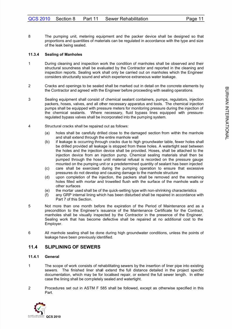
4 Where the insertion shaft is not at a manhole the jointing shall be accomplished using astainless steel full-encirclement clamp. If such jointing cannot be achieved, then a newmanhole shall be constructed. Recommended minimum lengths of clamps to afford adequatepullout protection are given in Table 11.1.
Table 11.1
Minimum Length of Clamps
OD of Liner Pipe Minimum Length of Clamp(mm) (mm)
90 190115 250135 250170 380180 380220 380270 500325 500340 500405 760455 760
475 760560 760661 760
5 Alternative pipe jointing methods shall be subject to the approval of the Engineer.
6 The liner shall be inserted with a power winch and steel cable connected to the end of theliner using of an appropriate pulling head. Where necessary a second pulling head may beattached to the other end of the liner for attachment of a tag line to pull the liner back out ofthe sewer.
7 Pulling shall be continued form start to completion without interruption, and precautions shallbe taken during insertion to protect the liner pipe so that any ragged edges of a broken sewerpipe will not score the outside of the liner.
8 The manufacturer s recommendations regarding relaxation of the liner shall be followedbefore sealing the annular space between the liner and existing sewer pipe. The annularspace between the polyethylene liner and the existing sewer shall be sealed using a methodapproved by the Engineer.
9 Where an existing manhole is used as an entrance shaft the manhole shall be reinstated togood condition or it shall be replaced with a new manhole in accordance with Part 4 of thisSection.
10 Foam sealant shall not protrude into the manhole and the sealant shall be finished over witha quick-setting, non-shrinking type of cement grout. Finishing inside the manhole shall beaccomplished using a quick-setting cement type grout to raise the manhole trough to theinvert of the liner pipe and reform the manhole benching as required. Exposed cement type

8/10/2019 qcs 2010 Part 11 Sewer Rehabilitation
http://slidepdf.com/reader/full/qcs-2010-part-11-sewer-rehabilitation 14/26
B U R H A N I N T
E R N A T I ON A L
QCS 2010 Section 8 Part 11 Sewer Rehabilitation Page 14
QCS 2010
grout surfaces shall be protected against corrosion by lining with GRP in accordance withClause 4.4.1 of this Section.
11 Precautions shall be taken to prevent collapsing of the liner owing to excessive groutingpressure.
12 The liner shall be secured in the upstream manhole. Each existing service connection shallbe excavated and reconnected to the new liner pipe using either polyethylene heat fusionsaddles or strap-on saddles as conditions require. A neoprene gasket shall be insertedbetween the liner and the strap-on saddle. Saddles shall be secured to the liner pipe usingstainless steel bands. Connections of saddle fittings to existing service connections shall bemade using elastomeric boots, full-encirclement clamps, or other methods approved by theEngineer.
13 Before backfilling any existing sewers that had been broken to open, the pipe shall berepaired and the annular space between the existing sewer and the new liner sealed usingcement or expandable foam to the approval of the Engineer.
14 At locations where the liner pipe has been exposed, the pipe and fittings shall be encased in
Grade 20 SRC concrete.
11.5 DEFORMED PIPE LINER INSTALLATION
11.5.1 Scope
1 The scope of the work consists of rehabilitating sewers by the insertion of a deformedthermoplastic pipe into existing sewers. The deformed pipe on the application of pressureand temperature or on release of deforming stress induced by swaging reverts to its pre-deformed shape to form a tight fit inside the host pipe without the formation of an annulus.
11.5.2 Materials
1 The HDPE liner material shall be designed for use in gravity sewers and shall be in strictconformance with all applicable sections of ASTM F1533.
2 The liner shall be made from High Density Polyethylene resins complying with ASTM D1248,Type III, Grade P34 and Cell Classification PE 345434C, D or E per ASTM D3350. TheContractor shall submit to the Engineer for approval certified test results from the liner pipemanufacturer to verify that the resin material used for extrusions of the liner meets thespecified requirements, including the quality control records during the liner extrusionprocess.
3 At the time of manufacture, each lot of liner shall be inspected for defects with samples beingtaken in accordance with ASTM D4703 and tested in accordance with ASTM D1693, ASTMD2837 and ASTM F714.
4 For testing purposes a production lot shall consist of all liner having the same markingnumber. It shall include all items produced during any given work shift and must be identifiedaccordingly to differentiate it from previous or following production.
5 Each deformed liner coil in compliance with ASTM F1533 shall be clearly marked by themanufacturer with the following information:
(a) ASTM F1533 designation.(b) Nominal outside diameter.(c) SDR.(d) Approximate coil length.(e) Standard material designation code.(f) Manufacturer s name.
8/10/2019 qcs 2010 Part 11 Sewer Rehabilitation
http://slidepdf.com/reader/full/qcs-2010-part-11-sewer-rehabilitation 15/26
B U R H A N I N T
E R N A T I ON A L
QCS 2010 Section 8 Part 11 Sewer Rehabilitation Page 15
QCS 2010
(g) Manufacturer s production code from which plant l ocation, machine and date ofmanufacture can be identified.
(h) The project or contract number.
6 Liner minimum wall thickness shall be determined by strength and minimum stiffnessrequirements.
7 The liner shall be fabricated from materials which will be resistant to internal exposure tosewage, sewage gases and reagents listed in Table 1 above, when tested in accordance withthe provisions of ASTM D543, to a temperature of 40°C.
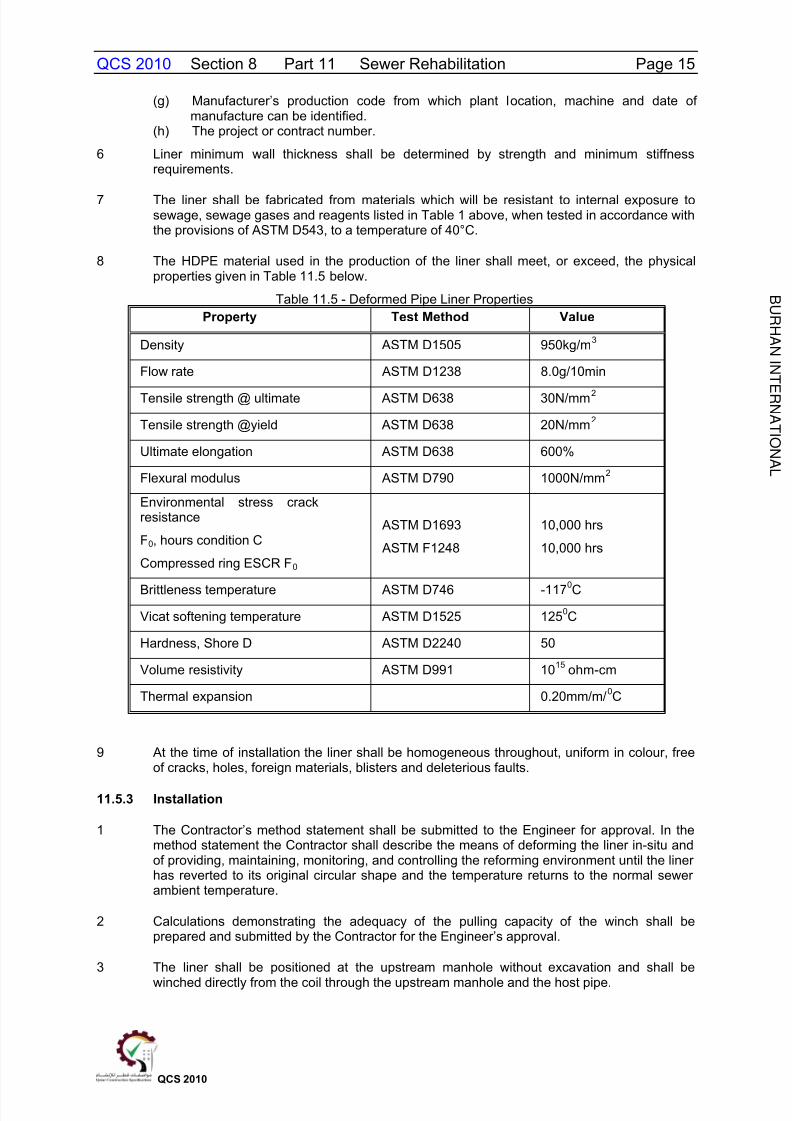
8 The HDPE material used in the production of the liner shall meet, or exceed, the physicalproperties given in Table 11.5 below.
Table 11.5 - Deformed Pipe Liner PropertiesProperty Test Method Value
Density ASTM D1505 950kg/m 3
Flow rate ASTM D1238 8.0g/10min
Tensile strength @ ultimate ASTM D638 30N/mm 2
Tensile strength @yield ASTM D638 20N/mm 2
Ultimate elongation ASTM D638 600%
Flexural modulus ASTM D790 1000N/mm 2
Environmental stress crackresistance
F 0, hours condition C
Compressed ring ESCR F 0
ASTM D1693
ASTM F1248
10,000 hrs
10,000 hrs
Brittleness temperature ASTM D746 -117 0C
Vicat softening temperature ASTM D1525 125 0C
Hardness, Shore D ASTM D2240 50
Volume resistivity ASTM D991 10 15 ohm-cm
Thermal expansion 0.20mm/m/ 0C
9 At the time of installation the liner shall be homogeneous throughout, uniform in colour, freeof cracks, holes, foreign materials, blisters and deleterious faults.
11.5.3 Installation
1 The Contractor s method statement shall be submitted to the Engineer for approval. In themethod statement the Contractor shall describe the means of deforming the liner in-situ andof providing, maintaining, monitoring, and controlling the reforming environment until the linerhas reverted to its original circular shape and the temperature returns to the normal sewerambient temperature.
2 Calculations demonstrating the adequacy of the pulling capacity of the winch shall beprepared and submitted by the Contractor for the Engineer s approval.
3 The liner shall be positioned at the upstream manhole without excavation and shall be
winched directly from the coil through the upstream manhole and the host pipe.
8/10/2019 qcs 2010 Part 11 Sewer Rehabilitation
http://slidepdf.com/reader/full/qcs-2010-part-11-sewer-rehabilitation 16/26
B U R H A N I N T
E R N A T I ON A L
QCS 2010 Section 8 Part 11 Sewer Rehabilitation Page 16
QCS 2010
4 Due care shall be exercised during winching to avoid damage to manholes and snagging.Guides or rollers shall be used within the manholes to avoid the risk of snagging.
5 The pulling winch shall be equipped with a tension gauge capable of controlled operation atvariable speed.
6 The pipe shall be cut flush at manhole inlet and outlet points using a rotary cutter and the joints sealed.
7 The Contractor shall adopt working practices for plastic pipes accordance with BS 5955.
8 The Contractor shall obtain detailed installation instructions and procedures from themanufacturer for the actual installation of the deformed and reformed system. Therequirements of ASTM F1606 shall also be satisfied.
9 When the deformed pipe liner is in place it shall be cut and the pipe end closing assemblyused for heat and pressure control within the liner shall be attached and secured at both pipeends. Temperature and pressure measuring instruments shall be attached to both ends ofthe deformed HDPE liner to provide a continuous monitor of the temperature and pressure
being applied to the liner.
10 Through the use of steam and air pressure the deformed pipe shall be reformed to conformto the existing pipe wall.
11 The reformed HDPE liner shall be cooled in accordance w ith the manufacturerrecommendations.
12 Temperatures and pressures shall be monitored and recorded throughout the installationprocess to ensure that each phase of the process is achieved at the manufacturer srecommended temperature and pressure limits
13 For each length of liner two samples shall be taken at locations determined by the Engineer.The sampling method shall include the use of a former to replicate the host pipe. Thesamples shall be clearly labelled with date taken and location. The samples shall be testedfor average inside diameter, average outside diameter and minimum wall thickness inaccordance with ASTM D2122, pipe stiffness at 5% deflection in accordance with ASTMD2412 and for the properties given in Table 3. The stiffness so measured shall meet, orexceed the stiffness requirements determined by calculation for that section of sewer line orthe minimum specified stiffness whichever is greater. Any material may be rejected for failingto meet any of the requirements of this specification.
14 The water tightness of the liner shall be gauged throughout the forming process.
11.6 CURED-IN-PLACE LINER INSTALLATION (INVERSION METHOD)
11.6.1 Scope
1 The scope of work consists of rehabilitating sewers by the installation of a resin impregnatedflexible felt tube inverted into existing sewers. When cured, the new material shall extendover the length of the inversion as a continuous, tight-fitting, watertight lining.

8/10/2019 qcs 2010 Part 11 Sewer Rehabilitation
http://slidepdf.com/reader/full/qcs-2010-part-11-sewer-rehabilitation 17/26
B U R H A N I N T
E R N A T I ON A L
QCS 2010 Section 8 Part 11 Sewer Rehabilitation Page 17
QCS 2010
11.6.2 Materials
1 The liner material shall be designed for use in gravity sewers and shall be in strictconformance with all applicable sections of ASTM F1216.
2 The felt liner tube shall be a thermoplastic polyester tube consisting of one or more layers of
flexible needled felt or an equivalent woven and/or non/woven material capable of carryingresin, and with sufficient needling and crosslapping and strength to withstand the installationpressures and curing temperatures.
3 The felt tube shall be compatible with the resin and catalyst systems to be utilised.
4 The finished liner shall consist of a felt layer (or layers) impregnated with a thermosettingresin and fabricated to fit tight against the host pipe. An allowance shall be made forcircumferential stretching during installation where applicable.
5 Each felt liner tube shall be clearly marked by the manufacturer with the followinginformation:
(a) Manufacturer s name. (b) Manufacturer s production code from which plant location, machine and date of
manufacture can be identified.(c) The project or contract number.
6 The lining technique shall comprise using a suitable preliner to prevent loss of resin.
7 The resin used shall be a general purpose, unsaturated, thermosetting, vinylester resin ableto cure in the presence or absence of water and a catalyst system compatible with theinsertion process that provides physical properties given in Table 11.6.
Table 11.6 - Cured in Place Liner Properties
Property Test Method ValueFlexural strength ASTM D790 31N/mm 2
Short term flexural modulus ASTM D790 1724N/mm
Long term flexural modulus ASTM D790 862N/mm
Tensile strength ASTM D638 21N/mm
8 The installed and cured liner shall be chemically resistant to exposure to sewage and sewagegases as experienced with the high temperatures in Qatar.
9 At the time of installation the liner shall be free of all visible tears, holes, cuts, foreignmaterials and other defects.
10 The liner shall be fabricated to a size that when installed will neatly fit the internalcircumference of the sewer being renovated. Allowance shall be made for circumferentialstretching during insertion. The minimum length shall be that deemed necessary by theContractor to effectively span the distance from inlet to outlet of the respective manholesunless otherwise designated in the contract specification. The Contractor shall verify thelengths on Site before impregnation. Individual inversion runs may be made over one ormore lengths of sewer as determined on Site by the Contractor and approved by theEngineer.
11.6.3 Installation of Cured-In-Place Liner
1 The following installation procedure shall be adhered to unless otherwise proposed in theContractor s method statement and approved by the Engineer:
8/10/2019 qcs 2010 Part 11 Sewer Rehabilitation
http://slidepdf.com/reader/full/qcs-2010-part-11-sewer-rehabilitation 18/26
B U R H A N I N T
E R N A T I ON A L
QCS 2010 Section 8 Part 11 Sewer Rehabilitation Page 18
QCS 2010
(a) the Contractor shall designate a location or locations where the reconstruction tube willbe vacuum impregnated before installation. The Contractor shall allow theEngineer to inspect the materials and wet-out procedure. A catalyst systemcompatible with the resin and reconstruction tube shall be used
(b) the Contractor shall provide facilities to control the temperature of the wet-outreconstruction tube to prevent premature setting of the resin
(c) the wet-out reconstruction tube shall be inserted through an existing manhole orother approved access by means of an inversion process and the application of aninversion medium of sufficient pressure and volume sufficient to fully extend it to thedesignated or termination point
(d) the inversion pressure shall be adjusted to be sufficient to cause theimpregnated tube to invert from manhole to manhole and hold the tube tight to thepipe wall and to produce dimples at side connections and flared ends at themanholes. Care shall be taken during the elevated curing temperature so as not tooverstress the felt fibre
(e) after inversion is complete, the Contractor shall provide a suitable curingenvironment. Monitoring and control equipment shall be provided to permitobservation and maintenance of the curing environment. Temperature and otherfactors of the curing environment shall be those recommended by the resin
manufacturer(f) should excessive infiltration into the sewer be present, a preliner shall be insertedinto the sewer line to prevent washout of the resin.
2 Initial curing shall be deemed to be completed when inspection of the exposed portions ofcured pipe appear to be hard and sound and the remote temperature sensor indicates thatthe temperature is of a magnitude to realise an exotherm. The curing period shall be thatrecommended by the resin manufacturer, as modified for the cured-in-place inversionprocess, during which time the Contractor shall maintain the quality of the curing environmentto the levels recommended by the resin manufacturer.
3 The Contractor shall cool the hardened liner to a temperature below 38 C before relievingthe pressure. Cooling may be accomplished by the introduction of cool water into theinversion standpipe to replace water being drained from a small hole made in thedownstream end. Care shall be taken in the release of the static head so that a vacuum willnot be developed that could damage the newly installed liner.
4 Where the new liner fails to make a tight seal due to broken or misaligned host pipe at themanhole wall, the Contractor shall apply a seal at that point. The seal shall be of a resinmixture compatible with the liner and the host pipe.
5 After the new liner has been cured in place, the Contractor shall reconnect existing activeservice connections as directed by the Engineer. Unless otherwise designated in the contractspecific documentation, shall be done without excavation. In the case of non -man-entrypipes from the interior of the system by means of CCTV cameras and a cutting devices thatre-establish the service connection and seal the joint at the point of entry of the serviceconnection.
6 The Contractor shall obtain detailed installation instructions and procedures from themanufacturer for the actual installation of the cured in place liner system. The requirementsof ASTM F1216 shall also be satisfied.
7 The section of pipeline to be lined shall have been cleaned, surveyed and repaired to therequirements of this section of the standard specification prior to liner installation.
8 For each length of liner two samples shall be taken at locations determined by the Engineer.Sampling method shall include the use of a former to replicate the host pipe. The samplesshall be clearly labelled with date taken and location. The samples shall be tested foraverage inside diameter, average outside diameter and minimum wall thickness inaccordance with ASTM D2122, pipe stiffness at 5% deflection in accordance with ASTMD2412 and for the properties given in Table 2. The stiffness so measured shall meet, orexceed the stiffness requirements determined by calculation for that section of sewer line or
8/10/2019 qcs 2010 Part 11 Sewer Rehabilitation
http://slidepdf.com/reader/full/qcs-2010-part-11-sewer-rehabilitation 19/26
B U R H A N I N T
E R N A T I ON A L
QCS 2010 Section 8 Part 11 Sewer Rehabilitation Page 19
QCS 2010
the minimum specified stiffness whichever is greater. Any material may be rejected for failingto meet any of the requirements of this specification.
9 The watertightness of the pipe shall be gauged while curing and under a positive head.
10 The beginning and end of the liner pipe shall be sealed to the rehabilitated pipeline and to the
manhole liner using a material that is compatible with the liner.
11 Wrinkles in the finished pipe which exceed 5% of the pipe diameter are unacceptable and theliner shall be removed and a replacement liner installed to the approval of the Engineer.
11.7 SPIRAL WOUND PROFILE LINER
11.7.1 Scope
1 The scope of work consists of rehabilitation of sewers by the installation of helically wound,profile walled thermoplastic pipe.
11.7.2 Materials
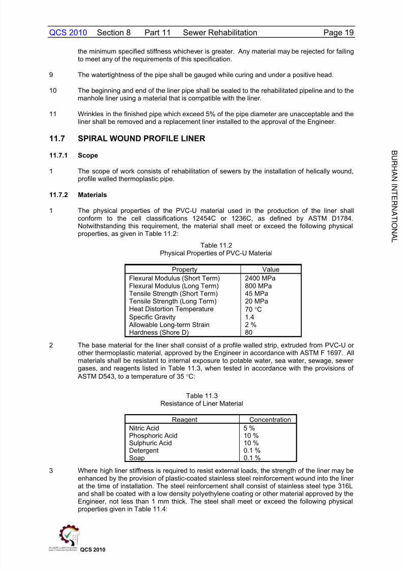
1 The physical properties of the PVC-U material used in the production of the liner shallconform to the cell classifications 12454C or 1236C, as defined by ASTM D1784.Notwithstanding this requirement, the material shall meet or exceed the following physicalproperties, as given in Table 11.2:
Table 11.2Physical Properties of PVC-U Material
Property ValueFlexural Modulus (Short Term) 2400 MPaFlexural Modulus (Long Term) 800 MPaTensile Strength (Short Term) 45 MPaTensile Strength (Long Term) 20 MPaHeat Distortion Temperature 70 CSpecific Gravity 1.4
Allowable Long-term Strain 2 %Hardness (Shore D) 80
2 The base material for the liner shall consist of a profile walled strip, extruded from PVC-U orother thermoplastic material, approved by the Engineer in accordance with ASTM F 1697. Allmaterials shall be resistant to internal exposure to potable water, sea water, sewage, sewergases, and reagents listed in Table 11.3, when tested in accordance with the provisions of
ASTM D543, to a temperature of 35 C:
Table 11.3Resistance of Liner Material
Reagent ConcentrationNitric Acid 5 %Phosphoric Acid 10 %Sulphuric Acid 10 %Detergent 0.1 %Soap 0.1 %
3 Where high liner stiffness is required to resist external loads, the strength of the liner may beenhanced by the provision of plastic-coated stainless steel reinforcement wound into the linerat the time of installation. The steel reinforcement shall consist of stainless steel type 316Land shall be coated with a low density polyethylene coating or other material approved by theEngineer, not less than 1 mm thick. The steel shall meet or exceed the following physicalproperties given in Table 11.4:
8/10/2019 qcs 2010 Part 11 Sewer Rehabilitation
http://slidepdf.com/reader/full/qcs-2010-part-11-sewer-rehabilitation 20/26
B U R H A N I N T
E R N A T I ON A L
QCS 2010 Section 8 Part 11 Sewer Rehabilitation Page 20
QCS 2010
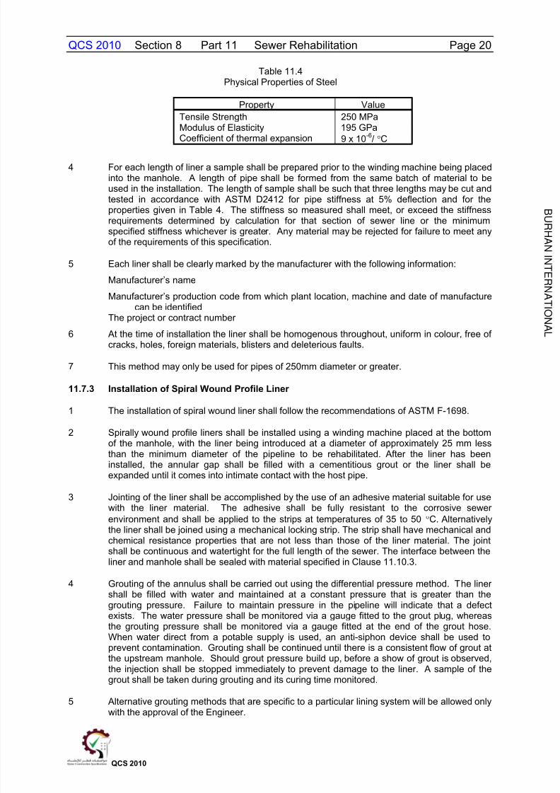
Table 11.4Physical Properties of Steel
Property ValueTensile Strength 250 MPaModulus of Elasticity 195 GPa
Coefficient of thermal expansion 9 x 10⁻⁶
/ C
4 For each length of liner a sample shall be prepared prior to the winding machine being placedinto the manhole. A length of pipe shall be formed from the same batch of material to beused in the installation. The length of sample shall be such that three lengths may be cut andtested in accordance with ASTM D2412 for pipe stiffness at 5% deflection and for theproperties given in Table 4. The stiffness so measured shall meet, or exceed the stiffnessrequirements determined by calculation for that section of sewer line or the minimumspecified stiffness whichever is greater. Any material may be rejected for failure to meet anyof the requirements of this specification.
5 Each liner shall be clearly marked by the manufacturer with the following information:
Manufacturer s name
Manufacturer s production code from which plant location, machine and date of manufacturecan be identified
The project or contract number
6 At the time of installation the liner shall be homogenous throughout, uniform in colour, free ofcracks, holes, foreign materials, blisters and deleterious faults.
7 This method may only be used for pipes of 250mm diameter or greater.
11.7.3 Installation of Spiral Wound Profile Liner
1 The installation of spiral wound liner shall follow the recommendations of ASTM F-1698.
2 Spirally wound profile liners shall be installed using a winding machine placed at the bottomof the manhole, with the liner being introduced at a diameter of approximately 25 mm lessthan the minimum diameter of the pipeline to be rehabilitated. After the liner has beeninstalled, the annular gap shall be filled with a cementitious grout or the liner shall beexpanded until it comes into intimate contact with the host pipe.
3 Jointing of the liner shall be accomplished by the use of an adhesive material suitable for usewith the liner material. The adhesive shall be fully resistant to the corrosive sewerenvironment and shall be applied to the strips at temperatures of 35 to 50 C. Alternativelythe liner shall be joined using a mechanical locking strip. The strip shall have mechanical andchemical resistance properties that are not less than those of the liner material. The joint
shall be continuous and watertight for the full length of the sewer. The interface between theliner and manhole shall be sealed with material specified in Clause 11.10.3.
4 Grouting of the annulus shall be carried out using the differential pressure method. The linershall be filled with water and maintained at a constant pressure that is greater than thegrouting pressure. Failure to maintain pressure in the pipeline will indicate that a defectexists. The water pressure shall be monitored via a gauge fitted to the grout plug, whereasthe grouting pressure shall be monitored via a gauge fitted at the end of the grout hose.When water direct from a potable supply is used, an anti-siphon device shall be used toprevent contamination. Grouting shall be continued until there is a consistent flow of grout atthe upstream manhole. Should grout pressure build up, before a show of grout is observed,the injection shall be stopped immediately to prevent damage to the liner. A sample of thegrout shall be taken during grouting and its curing time monitored.
5 Alternative grouting methods that are specific to a particular lining system will be allowed onlywith the approval of the Engineer.
8/10/2019 qcs 2010 Part 11 Sewer Rehabilitation
http://slidepdf.com/reader/full/qcs-2010-part-11-sewer-rehabilitation 21/26
B U R H A N I N T
E R N A T I ON A L
QCS 2010 Section 8 Part 11 Sewer Rehabilitation Page 21
QCS 2010
11.8 PIPE CRACKING OR BURSTING
11.8.1 Scope
1 Rehabilitation of sewers by the replacement of existing pipes with polyethylene (PE) orpolypropylene (PP) pipes by breaking the existing pipes, expanding the hole size andinserting the replacement pipes in one operation with a minimum of disturbance to thesurrounding ground and no surface disruption.
11.8.2 General
1 The Contractor shall satisfy the Engineer that the pipe bursting procedures will not havedetrimental effects on adjacent utilities or structures, particularly from vibration arising fromuse of pneumatic bursters. The Contractor shall be responsible for such damage and shallbear the cost of rectification.
2 The Contractor shall comply with the requirements of service authorities and shall bedeemed to have identified the location of services which may be affected by the Works.Unless otherwise required by the service authorities, where services are known to be locatedwithin one meter of the pipe to be burst, the Contractor shall expose the service in advanceof pipe bursting. A minimum free space of 500 mm shall be created beneath the service overa length to be agreed between the Contractor and the service authorities.
11.8.3 Materials
1 The materials used for replacement of the existing pipes shall be polyethylene orpolypropylene unless otherwise specified in the contract documents.
2 The method of jointing the pipes shall be as the manufacturer s recommendations for theapplication. Unless otherwise specified or approved by the Engineer pipe joints shall bedesigned to be watertight against external water pressure assuming that groundwaterextends to the ground surface.
11.8.4 Installation Equipment
1 Pipe bursting equipment shall be hydraulically or pneumatically powered incorporating anexpander at the nose of the machine which will fragment the existing pipe and expand thespace uniformly to a diameter sufficient to allow the replacement pipe to be inserted. Theannular space between the expander and the replacement pipe shall not exceed 20 mmunless otherwise agreed by the Engineer.
2 The method of inserting the replacement pipe shall be such that stresses transmitted to thereplacement pipe shall not damage the pipes or exceed the tensile capacity of thereplacement pipe.
3 Pipe bursting equipment shall be capable of
(a) Working from existing manholes so that they can be used as launch and receptionshafts wherever possible. Provision shall be made for remote starting and stopping.
(b) Dealing with small quantities of unreinforced concrete of maximum 150 mm nominalthickness found surrounding pipes, joints, saddles and service connections and forbursting pipes laid on a concrete cradle without being deflected off line and level.
(c) Working under a hydrostatic pressure of groundwater.(d) Operating at maximum depth of 10.0 m from surface level.(e) Operation without jamming of moving parts or other malfunction due to the ingress of
groundwater or sand particles.
4 Where the Contractor has not previously used the equipment or demonstrated the pipebursting technique to the satisfaction of the Engineer then he shall demonstrate the suitabilityof the equipment as follows:
8/10/2019 qcs 2010 Part 11 Sewer Rehabilitation
http://slidepdf.com/reader/full/qcs-2010-part-11-sewer-rehabilitation 22/26
B U R H A N I N T
E R N A T I ON A L
QCS 2010 Section 8 Part 11 Sewer Rehabilitation Page 22
QCS 2010
(a) construct in open ground at a location approved by the Engineer, a 50m longtemporary section of pipe of the same bore and material as the sewer to berehabilitated at similar depth, complete with unbenched chambers at each end;
(b) backfill the excavation;(c) demonstrate the pipe bursting procedure.(d) on completion of the pipe installation flood the site to artificially bring the water table to
the ground surface and demonstrate that infiltration requirements of Part 4 of thisSection are met.
5 Should difficulties be encountered in completing the trial installation the Contractor shallmodify his proposal for approval by the Engineer before recommencing work.
6 Measures shall be taken to ensure that the replacement pipe does not become separatedfrom the pipe expander should the system employ an insertion technique which allows thereplacement pipe to slide within the pipe expander.
11.8.5 Installation
1 Shafts for launch and reception shall be existing manholes and excavations made overexisting inspection chambers and service connections where the latter are proposed to bereconnected to the pipeline. Service connections to be abandoned or redirected to upstreamor downstream chambers or manholes shall not be excavated.
2 Unless specifically approved by the Engineer pipe bursting shall not be carried out byconstructing shafts adjacent to manholes. Where necessary, the channel, benching andwalls of existing manholes shall be altered to receive the pipe bursting equipment. Allmanhole alterations shall be made good.
3 The Contractor s attention is drawn to the potential problems arising from the inflow ofgroundwater and loss of ground from the outside of manholes. His proposed method ofworking shall take these into consideration and shall be subject to the Engineer s approvaland shall ensure that no inflow of groundwater or loss of ground occurs. Where manholesare located in roads, the Contractor shall obtain permission from the Roads Division prior tocarrying out any wellpoint dewatering operations around the manhole. In the event thatmeans of stabilising the ground around the manhole and connecting pipelines are notapproved by the Engineer, the Contractor shall not use pipe bursting methods at that locationunless any other alternative method is approved by the Engineer.
4 Existing service connections shall be disconnected from the existing pipeline in advance ofpipe bursting and reconnected on completion of the installation of the replacement pipe. Inthe interval, the Contractor shall maintain service by temporarily connecting serviceconnections to the sewerage system downstream of the section, by overpumping, or by suchother method the Contractor may propose for the Engineer s approval.
5 Sewer lengths to be rehabilitated shall be checked for the presence of collapses occurringsubsequent to cleaning by gauging between shafts. Where a collapse is detected its positionshall be determined and an additional shaft shall be excavated if the debris cannot beremoved.
6 Pipe bursting shall not commence unless sufficient lengths of replacement pipes areavailable on Site to complete the length of pipe to be rehabilitated.
7 Where pipe bursting is delayed for a period exceeding 7 days following cleaning, the pipelineshall be reinspected.
8 Winching shall conform to the following requirements:
(a) Details of the proposed winching method shall be submitted to the Engineer forapproval at least 7 days before the insertion date
(b) Winches shall be of the constant load type fitted with a direct reading load gauge. Atthe end of each day s work, the Contractor shall provide the Engineer with a copy of

8/10/2019 qcs 2010 Part 11 Sewer Rehabilitation
http://slidepdf.com/reader/full/qcs-2010-part-11-sewer-rehabilitation 23/26
B U R H A N I N T
E R N A T I ON A L
QCS 2010 Section 8 Part 11 Sewer Rehabilitation Page 23
QCS 2010
the winching loads recorded at the start of any pull and during the pull at increments of20 m of winching distance and at any restart following temporary stops
(c) Winches shall be fitted with an automatic device to disengage when the loadexceeds a preset maximum load.
(d) The Contractor shall supply sufficient cable in one continuous length to ensure thepull is continuous between approved winching points
(e) Winches, cables and cable drums shall be provided with safety cages and supports(f) The Contractor shall provide a system of guide pulleys and bracings at each manhole(g) Nose cones fixed to the head of pipe expanders shall be fitted with a swivel
attachment to prevent twist transmission between the winch cable and the nose cone(h) Where the Contractor proposes to use a lubricant to ease the pull, the type of
lubricant, method of introduction, removal and quantity to be used shall be submittedfor the Engineer s approval before beginning winching
(i) Trench sidewall support in the insertion trench shall remain completely separate fromthe pipe support system and shall be designed so as not to be in contact with the pipeor the winch cable.
9 Replacement pipe shall be inserted in accordance with the following requirements:
(a) the maximum force shall be within the stress limit of the pipe
(b) continuous length pipelines shall not be used. The maximum pipe length for insertionshall be 1.5 m where pipe bursting is undertaken between excavated shafts and either700 mm or 800 mm where pipe bursting is undertaken from manhole to manhole
(c) where a device is employed to exert force on the rear of the inserted pipe lengths, theforce applied to the inserted pipe shall be evenly distributed around the wall of thepipe
(d) Where lengths of pipe are joined and a device is employed to exert force to the rear ofthe inserted pipe lengths, precautions shall be taken to ensure that no buckling,crushing, twisting, or damage to the joint of the pipe takes place. Where, in theopinion of the Engineer, excessive deformation of the pipe has taken place, the pipeshall be replaced at the Contractor s expense.
10 Where the lining is to be joined using „Snap -Lock or sim ilar fittings, the Contractor shallcomply with the manufacturer s recommendations for jointing. Means of verifying the criticaldimensions of the joints shall be provided on site by the Contractor. The joint shall be fittedwith a suitable sealing ring and shall be designed to be watertight against an excess externalwater pressure of 20 metres head.
11.9 INSPECTION AND TESTING OF PIPE LINES AFTER REHABILITATION
1 The completed sewer shall meet the leakage requirements of pressure tests or air tests asspecified in Part 4 of this Section.
2 After completion of each length of sewer, the Contractor shall flush the pipeline andundertake a CCTV and deflection survey and provide video tapes, pictures on digital formatand site coding sheets to the Engineer.
3 Where necessary the Contractor shall remove any debris and carry out any remedial workidentified. Upon completion of remedial work and removal of debris the section shall beresurveyed and the Engineer provided with the latest CCTV video tapes. Further additionalCCTV surveys resulting from the need to again clean or carry out further remedial work shallbe at no additional cost to the Employer.
4 The rehabilitated sewer shall be returned to service only after the written approval of theEngineer.
5 During the guarantee period any defects which will affect the integrity or strength of the pipeshall be repaired at the Contractor s expense, in a manner mutually agreed by the Engineerand the Contractor.

8/10/2019 qcs 2010 Part 11 Sewer Rehabilitation
http://slidepdf.com/reader/full/qcs-2010-part-11-sewer-rehabilitation 24/26
B U R H A N I N T
E R N A T I ON A L
QCS 2010 Section 8 Part 11 Sewer Rehabilitation Page 24
QCS 2010
11.10 MANHOLE REHABILITATION
11.10.1 Scope
1 The scope of work consists of the materials and types and methods of repair for therehabilitation of manholes.
11.10.2 General
1 Manhole rehabilitation shall comprise but not be limited to any combination of the following:
(a) Rehabilitation of walls or bases by plugging, patching, and removing, providing orreplacing mortars, coatings, sealants and liners, to improve structural condition,prevent infiltration, provide corrosion protection or external tanking protection.
(b) Repair of shaft and cover slab and reconstruction to the required level(c) Reinstallation or replacement of manhole frame and cover(d) Installation of manhole sealing plate.
11.10.3 Materials
1 Materials used shall be suitable proprietary materials for manhole rehabilitation and thespecific application in which they are used. The materials shall be supplied in factory-labelledcontainers. All materials shall be mixed and applied in accordance with the manufacturer sinstructions.
2 Materials used for plugging holes and stopping infiltration in manholes shall be either:
(a) Premixed hydraulic cement consisting of Portland cement, graded silica aggregates,special plasticising and accelerating agents with a set time of approximately 50 s anda 10 min compressive strength of approximately 3.5 MPa and free of chlorides,gypsum, plasters, iron particles, or gas-forming agents
(b) Siliconate-based liquid accelerator mixed with neat Portland cement with a set time of
approximately 50 s.3 Materials used for patching, filling and repairing non-infiltration holes, cracks, and breaks in
concrete and masonry manholes shall comprise a premixed Portland cement-basedhydraulic cement consisting of Portland cement, graded silica aggregates, special plasticisingand accelerating agents with a set time of approximately 3 min or 15 min to suit applicationand a one-hour compressive strength of approximately 4.2 MPa. It shall not containchlorides, gypsum, plasters, iron particles, or gas-forming agents.
4 Materials used for waterproofing membrane, corrosion protection, and strengthening ofconcrete and block work manholes shall be:
(a) liquid polymer modified water based waterproof coating which shall provide a securemechanical and chemical bond with a curing time of approximately 1.5 h and a
cured compressive strength of approximately 40 MPa. The coating shall be appliedwith a brush to surfaces without cracks or voids wider than 1.5 mm
(b) 100 % solids, three-component system consisting of a two-component epoxy resinand a special blend of fillers which shall provide a secure mechanical and chemicalbond with an initial curing time of approximately 4 h and a cured compressivestrength of approximately 76 MPa. The resin with fillers shall be applied with a trowelto a thickness of 3 mm to 12 mm. Epoxy resin (without fillers) used for waterproofingand corrosion protection shall be applied with a brush.
5 Remove all defective linings together with 100mm of adjoining good lining in existingmanholes and other structures, including areas of lining covering leakage points.
6 Break out defective concrete to sound concrete surface.

8/10/2019 qcs 2010 Part 11 Sewer Rehabilitation
http://slidepdf.com/reader/full/qcs-2010-part-11-sewer-rehabilitation 25/26
B U R H A N I N T
E R N A T I ON A L
QCS 2010 Section 8 Part 11 Sewer Rehabilitation Page 25
QCS 2010
7 Apply approved epoxy bonding agent and reinstate concrete using an approved concreterepair material.
11.10.4 Rehabilitation of Manhole Walls and Bases
1 Surfaces of manhole walls and bases shall be thoroughly cleaned to remove all loose
material and surface contaminants. Cleaning shall be accomplished by pressure jetting,sandblasting, or applying a 10 % solution of muriatic acid or hydrochloric acid. Where an acidsolution is used the surface shall be thoroughly rinsed and neutralised before the applicationof mortars and coatings.
2 After surface preparation and before the application of mortars and coatings, infiltration shallbe stopped by sealing as specified in Clause 11.3.4.
11.10.5 Rehabilitation of Manhole Shafts and Slabs
1 The Contractor shall take all necessary precautions to prevent debris from damaging themanholes and the sewer.
2 Shafts and cover slabs shall be repaired and rehabilitated with suitable sound materialsapproved by the Engineer.
3 Rings shall be provided as appropriate to reconstruct the shaft to the required elevation.
11.10.6 Manhole Cover, Frame and Sealing Plate Reinstallation or Replacement
1 The Contractor shall remove covers, frames, and sealing plates. Where the Engineerdetermines that cover, frames and sealing plates are to be replaced, the Contractor shalldispose of them.
2 The Contractor shall adjust the level and slope of the manhole cover as required. Themanhole shall be raised by building precast concrete rings.
3 Covers and frames determined by the Engineer to be in good condition shall be grit blastedand coated on all exposed faces with a zinc primer and coal-tar epoxy paint finish asspecified for System C in Part 8 of this Section. Replacement covers, frames and sealingplates shall be as specified in Part 6 of this Section.
4 The Contractor shall reinstall or replace the manhole cover and frame using either of thefollowing methods in accordance with the Contract Drawings and clause 4.4 of this Section.
5 Sealing plates shall be installed as specified in Part 6 of this Section.
11.10.7 Inspection and Testing
1 Completed rehabilitation works shall be visually inspected in the presence of the Engineer.Work that has become defective shall be redone at no additional cost to the Employer.
11.11 MANHOLE LINING
11.11.1 Scope
1 The scope of work comprises structural rehabilitation of manholes by the installation of in-situglass fibre reinforced manhole liners.
11.11.2 Materials
GRP liner materials shall be as specified in Part 7 of this Section.
8/10/2019 qcs 2010 Part 11 Sewer Rehabilitation
http://slidepdf.com/reader/full/qcs-2010-part-11-sewer-rehabilitation 26/26
B U R H A N I N T
E R N A T I ON A L
QCS 2010 Section 8 Part 11 Sewer Rehabilitation Page 26
11.11.3 Installation of Lining
1 The cover slab and manhole cover shall be removed and disposed of off Site. The manholecover and frame shall be thoroughly cleaned, treated with two coats of bituminous paint anddelivered to CED store and placed into storage.
2 Step irons shall be removed and the walls made good and prepared with 3:1 sand/cementmortar.
3 Concrete surfaces to be lined shall be cleaned and lightly abraded prior to the application ofthe GRP. The GRP lining shall be built up by applying isophthalic or vinyl ester resin. A layerof ECR glass mat shall then be rolled into the resin using a suitable steel roller to exclude allair and provide complete immersion of the glass fibre in the resin. After a period to allow pre-gel to a tacky state, a second coat of resin shall be applied followed by a further layer of glassfibre mat. This process shall be repeated until the total thickness of lining is approximately4 mm. Vinyl ester resin and “C” glass veil shall then be used to complete the lining.
4 Top surfaces of benching shall incorporate silica sand to form a non-slip surface.
5 The precast cover slab shall be seated on the walls using sand/cement mortar. The joint shallbe raked out 15 mm deep on the inside face and pointed with an approved pitch extendedpolyurethane sealant.
6 GRP ladders of an approved pattern as specified may be purpose made to suit the depth ofeach manhole. Fixings for ladders shall be approved stainless steel stud anchors. Fixingholes shall be grouted with epoxy mortar and sealed as above. Rungs or treads shall beribbed to provide a non-slip surface.
11.11.4 Inspection and Testing
1 After the manhole lining has been installed, the manhole shall be visually inspected in thepresence of the Engineer and subject to the approval of the Engineer.
2 Before the expiration of the Period of Maintenance, the Contractor shall visually inspect thelined manholes in the presence of the Employer or Engineer. Work that has becomedefective shall be redone at no additional cost to the Employer.
END OF PART