Q1 line temperature controller Heat/Cool - Eltime temperature controller 1 / 4 DIN - 96 x 96 Q1 line...
61
Heat/Cool temperature controller 1 / 4 DIN - 96 x 96 Q1 line c User Manual • M.I.U. Q1 - 3/07.05 • Cod. J30-478-1AQ1 IE ASCON spa 20021 Baranzate (Milan) Italy via Falzarego, 9/11 Fax +39 02 350 4243 http://www.ascon.it e-mail [email protected] ASCON spa ISO 9001 Certified U L C US LISTED
-
Upload
nguyenphuc -
Category
Documents
-
view
227 -
download
2
Transcript of Q1 line temperature controller Heat/Cool - Eltime temperature controller 1 / 4 DIN - 96 x 96 Q1 line...

Heat/Cool temperature controller1/4 DIN - 96 x 96
Q1 line ccU s e r M a n u a l • M . I . U . Q 1 - 3 / 0 7 . 0 5 • C o d . J 3 0 - 4 7 8 - 1 A Q 1 I E
ASCON spa20021 Baranzate(Milan) Italyvia Falzarego, 9/11Fax +39 02 350 4243http://www.ascon.ite-mail [email protected]
ASCON spa
ISO 9001C e r t i f i e d
ULC US
LISTED
Q1 UK-ed3 7-04-2008 11:30 Pagina 1

Heat / Cool temperature controller1/4 DIN - 96 x 96
Q1 line cc
Q1
1 2 3
SP
PV
AT
S2S1
REM45.8045 .80SCI
RUN
ULC US
LISTED
Q1 UK-ed3 7-04-2008 11:30 Pagina 1

ccNOTES
ON ELECTRIC
SAFETY AND
ELECTROMAGNETIC
COMPATIBILITY
2
Information
Please, read carefully these instructions before proceeding with the installation of thecontroller.Class II instrument, real panel mounting.
This controller has been designed with compliance to:Regulations on electrical apparatus (appliance, systems and installations) according tothe European Community directive 73/23/EEC amended by the European Comunity direc-tive 93/68/EEC and the Regulations on the essential protection requirements in electricalapparatus EN61010-1 : 93 + A2:95.
Regulations on Electromagnetic Compatibility according to the European Communitydirective n089/336/EEC, amended by the European Community directive n° 92/31/EEC,93/68/EEC, 98/13/EEC and the following regulations:Regulations on RF emissions:
EN61000-6-3: 2001 residential environmentsEN61000-6-4: 2001 industrial environments
Regulation on RF immunity EN61000-6-2: 2001 industrial equipment and system
It is important to understand that it’s responsibility of the installer to ensure the complianceof the regulations on safety requirements and EMC.The device has no user serviceable parts and requires special equipment and specialisedengineers. Therefore, a repair can be hardly carried on directly by the user. For this purpose,the manufacturer provides technical assistance and the repair service for its Customers. Please, contact your nearest Agent for further information.All the information and warnings about safety and electromagnetic compatibility aremarked with the B sign, at the side of the note.
Q1 UK-ed3 7-04-2008 11:30 Pagina 2

3
Table of contents
TABLE OF CONTENTS
1 INSTALLATION ...................................................Page 42 ELECTRICAL CONNECTIONS .............Page 83 PRODUCT CODING ......................................Page 164 OPERATIONS ......................................................Page 215 DISPLAYS ...............................................................Page 476 COMMANDS ........................................................Page 487 TECHNICAL SPECIFICATIONS ...........Page 52
Main universal input
Control Alarms Retransmission
Resources
PV
AUX
Modbus RS485ParameterisationSupervision(option)
Q1
Setpoint Fuzzy tuning with automatic selection
One shotAuto tuning
One shotNatural Frequency
Operating mode
1212
Auxiliary input
Special functions (option)
PV / SP
1 OP1 OP2 OP3 OP5Single
2action
OP4 OP1 OP2 OP3 OP5
3 OP1 OP2 OP3 OP5
4 Double OP1 OP4 OP2 OP3 OP5action
5 OP4 OP2 OP1 OP3 OP5
OP1
OP2
OP3
OP4
OP5
(option)
(option)
Q1 UK-ed3 7-04-2008 11:30 Pagina 3

4
1 - Installation
1 INSTALLATION
Installation must only be carried out byqualified personnel.
Before proceeding with the installation ofthis controller, follow the instructions illus-trated in this manual and, particularly theinstallation precautions marked with theB symbol, related to the EuropeanCommunity directive on electrical protectionand electromagnetic compatibility.
BTo prevent hands or metal touching partsthat may be electrically live, the controllersmust be installed in an enclosure and/orin a cubicle.
IP 20 Terminal BlockEN61010 - 1 (IEC1010 - 1)
Product code label
Sealing front panel gasket
Mounting clamps
Front panelIP65 protectionEN 650529 (IEC 529)
Panelsurface
1.1 GENERAL DESCRIPTION
Q1 UK-ed3 7-04-2008 11:30 Pagina 4

5
1 - Installation
1.2 DIMENSIONS 1.3 PANEL CUT-OUT
96 mm3.78 in
110 mm4.33 in
10 mm max.0.39 in max.
10 mm max.0.39 in max.
96 mm3.78 in
92+
0.8
mm
3.62
+0.
031
in
113
mm
min
.4.
45 i
n m
in.
92+0.8 mm3.62+0.031 in
103 mm min.4.05 in min.
Q1 UK-ed3 7-04-2008 11:30 Pagina 5
6
1 - Installation
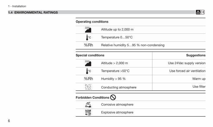
Operating conditions
M Altitude up to 2,000 m
T Temperature 0…50°C
%Rh Relative humidity 5…95 % non-condensing
1.4 ENVIRONMENTAL RATINGS B
Special conditions
M Altitude > 2,000 m
T Temperature >50°C
%Rh Humidity > 95 %
P Conducting atmosphere Use filter
Warm up
Use forced air ventilation
Use 24Vac supply version
Suggestions
Forbidden Conditions D
C Corrosive atmosphere
E Explosive atmosphere
Q1 UK-ed3 7-04-2008 11:30 Pagina 6

7
1 - Installation
1.5.1 INSERTTHE INSTRUMENT
1 Prepare panel cut-out;2 Check front panel gasket
position;3 Insert the instrument through
the cut-out.
1.5.2 INSTALLATION SECURING
1 Fit the mounting clamps;2 Push the mounting clamps
towards the panel surface tosecure the instrument.
1
3
2
1.5.3 CLAMPS REMOVING
1 Insert the screwdriver in theclips of the clamps;
2 Rotate the screwdriver.
2
1
1.5.4 INSTRUMENTUNPLUGGING B
1 Push and 2 pull to remove the instrument.
Electrostatic discharges candamage the instrument.Before removing the instrumentthe operator must dischargehimself to ground.
1 2
1
2
1.5 PANEL MOUNTING [1]
2
1
1
UL note[1] For Use on a Flat Surface of a Type 2 and Type 3‘raintight’ Enclosure.
1 M Ω
Q1 UK-ed3 7-04-2008 11:30 Pagina 7
28
27
30
29
26
25
19 31
8 20 32
9 33
10 34
11 23 35
12 24 36
0,5Nm
5.7 mm0.22 in
Rear terminal cover
Cable size1 mm2 [2]
3
2
1
8
2 - Electrical connections
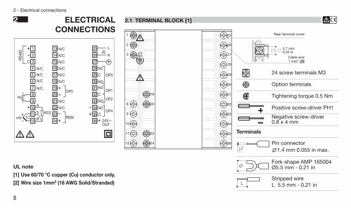
2 ELECTRICALCONNECTIONS
UL note
[1] Use 60/70 °C copper (Cu) conductor only.
[2] Wire size 1mm2 (18 AWG Solid/Stranded)
24 screw terminals M3
Option terminals
Tightening torque 0.5 Nm
Positive screw-driver PH1
Negative screw-driver0.8 x 4 mm
Terminals
Pin connectorq1.4 mm 0.055 in max.
ØFork-shape AMP 165004Ø5.5 mm - 0.21 in
LStripped wireL 5.5 mm - 0.21 in
N
L
RS4
85
1
2
3
8
9
10
11
12
19
20
23
24
25
26
27
28
29
30
31
32
33
34
35
36
TA
TCmV
NC
C
NO
OP3
NO
C
NO
OP1
OP2
OP4
C
REM
OP5
24V—OUT
A
b
B
RTD
13
14
15
16
17
18
21
22
7
4
5
6
N/C
N/C
N/C
N/C
N/C
N/C
N/C
N/C
N/C
N/C
N/C
N/C NO
C
2.1 TERMINAL BLOCK [1] B
Q1 UK-ed3 7-04-2008 11:30 Pagina 8

28
27
30
29
26
25
19 31
8 20 32
9 33
10 34
11 23 35
12 24 36
28
27
30
29
26
25
19 31
8 20 32
9 33
10 34
11 23 35
12 24 36
A B
E C C
3
2
1
A B
E C C
3
2
1
9
2 - Electrical connections
PRECAUTIONS BDespite the fact that the instru-ment has been designed to workin an harsh and noisy environ-mental (level IV of the industrialstandard IEC 801-4), it is recom-mended to follow the followingsuggestions.
AAll the wiring must comply withthe local regulations. The supply wiring should be rout-ed away from the power cables.Avoid to use electromagneticcontactors, power Relays andhigh power motors nearby.Avoid power units nearby, espe-cially if controlled in phase angle.
Keep the low level sensor inputwires away from the power linesand the output cables.If this is not achievable, useshielded cables on the sensorinput, with the shield connectedto earth.
Conduit for supply and output cables
Conduit for low level sensor cables
2.2 SUGGESTED WIRES ROUTING B
A = SupplyB = OutputsC = Analog inputsD = Analogue outputE = Digital input/output Serial Comm.s
Q1 UK-ed3 7-04-2008 11:30 Pagina 9

10
2 - Electrical connections
2.3 EXAMPLE OF WIRING DIAGRAM (HEAT / COOL CONTROL) B
Notes:1] Make sure that the power supply voltage is
the same indicated on the instrument.2] Switch on the power supply only after that
all the electrical connections have beencompleted.
3] In accordance with the safety regulations,the power supply switch shall bring theidentification of the relevant instrument. Thepower supply switch shall be easily acces-sible from the operator.
4] The instrument is is PTC protected. In caseof failure it is suggested to return the instru-ment to the manufacturer for repair.
5] To protect the instrument internal circuits use:- 2 A~ T fuse for Relay outputs (220 Vac);- 4 A~ T fuse for Relay outputs (110 Vac);- 1 A~ T fuse for Triac outputs.
6] Relay contacts are already protected withvaristors.Only in case of 24 Vac inductive loads,use model A51-065-30D7 varistors (onrequest).
Commands
RS485Powersupplyswitch
CAlarm
V ~
Cooling
Heating
[3]
[6]
[6]
[5]
[5]
OP3
OP1
OP2
CT Current transformer 50 mA ~
OP5V~
[6]
[5]
V~
PTC
Retransmission
12
11
10
9
8
3
2
1
24
23
20
19
36
35
34
33
32
31
30
29
28
27
26
25
Q1 UK-ed3 7-04-2008 11:30 Pagina 10

11
2 - Electrical connections
2.3.1 POWER SUPPLY B
Switching power supply with mul-tiple isolation and internal PTC.• Standard version:
- nominal voltage:100...240Vac (-15...+10%);
- frequency 50/60Hz.• Low Voltage version:
- nominal voltage: 24Vac (-25...+12%);
- frequency 50/60Hz or 24Vdc (-15...+25%).
Power consumption 4W max.
For better protection againstnoise, it is recommended not toconnect the earth clamp provid-ed for civilian installations.
L
N
25
26
Included PTC
Supply
27
2.3.2 PV CONTROL INPUT B
A L-J-K-S-R-T-B-N-E-W thermocouple type• Connect the wires with the polarity as shown;• Use always compensation cable of the correct type
for the thermocouple used;• The shield, if present, must be connected to a prop-
er earth.
B For Pt100 resistance thermometer• If a 3 wires system is used, use always cables of the
same diameter (1mm2 min.) (line 20 Ω/lead maximumresistance);
• When using a 2 wires system, use always cables of thesame section (1.5mm2 min.) and put a jumper betweenterminals 11 and 12.
C For ∆T (2x RTD Pt100) SpecialAWhen the distance between the controller and the
sensor is 15 m using a cable having a section of 1.5mm2, produces an error on the measure of 1°C.
R1 + R2 must be <320Ω.
Wire resistance150Ω max.
For 3 wires onlyMaximum lineresistance 20 Ω/line
Use wires of the samelength and 1.5 mm2
size.Maximum lineresistance 20 Ω/line
10
11
12
A
B
A
R2
R1
10
11
12
A
b
B
11
12
Q1 UK-ed3 7-04-2008 11:30 Pagina 11
12
2 - Electrical connections
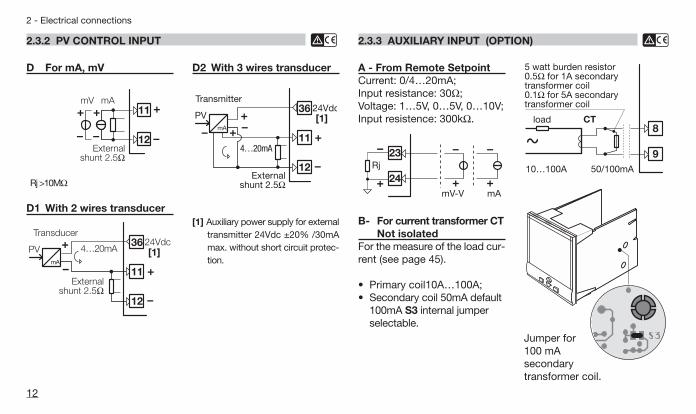
2.3.2 PV CONTROL INPUT B
D For mA, mV
Rj >10MΩ
D1 With 2 wires transducer
24Vdc4…20mA
Externalshunt 2.5Ω
Transducer
PV36
11
12
[1]mA
mV mA11
12External
shunt 2.5Ω
D2 With 3 wires transducer
[1] Auxiliary power supply for externaltransmitter 24Vdc ±20% /30mAmax. without short circuit protec-tion.
24Vdc
4…20mA
Externalshunt 2.5Ω
Transmitter
PV36
11
12
[1]mA
A - From Remote SetpointCurrent: 0/4…20mA;Input resistance: 30Ω;Voltage: 1…5V, 0…5V, 0…10V;Input resistence: 300kΩ.
2.3.3 AUXILIARY INPUT (OPTION) B
B- For current transformer CTNot isolated
For the measure of the load cur-rent (see page 45).
• Primary coil10A…100A;• Secondary coil 50mA default
100mA S3 internal jumperselectable.
9
8
10…100A 50/100mA
load CT
~
5 watt burden resistor0.5Ω for 1A secondarytransformer coil0.1Ω for 5A secondarytransformer coil
S3
24
23
mAmV-V
Rj
Jumper for 100 mA secondary transformer coil.
Q1 UK-ed3 7-04-2008 11:30 Pagina 12
13
2 - Electrical connections
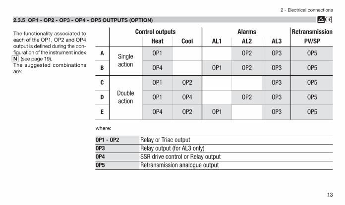
2.3.5 OP1 - OP2 - OP3 - OP4 - OP5 OUTPUTS (OPTION) B
The functionality associated toeach of the OP1, OP2 and OP4output is defined during the con-figuration of the instrument indexn(see page 19).The suggested combinationsare:
OP1 - OP2 Relay or Triac outputOP3 Relay output (for AL3 only)OP4 SSR drive control or Relay outputOP5 Retransmission analogue output
where:
Control outputs Alarms RetransmissionHeat Cool AL1 AL2 AL3 PV/SP
A Singleaction
OP1 OP2 OP3 OP5
B OP4 OP1 OP2 OP3 OP5
C
Double action
OP1 OP2 OP3 OP5
D OP1 OP4 OP2 OP3 OP5
E OP4 OP2 OP1 OP3 OP5
Q1 UK-ed3 7-04-2008 11:30 Pagina 13

14
2 - Electrical connections
2.3.5-A SINGLE ACTION RELAY(TRIAC) CONTROL OUTPUT B
2.3.5-B SINGLE ACTION SSR DRIVECONTROL OUTPUT B
2.3.5-C SINGLE ACTION ANALOGUE OUTPUT B
2.3.5-D DOUBLE ACTIONRELAY (TRIAC)/RELAY (TRIAC) CONTROL OUTPUT B
2.3.5-E DOUBLE ACTION RELAY (TRIAC)/SSR DRIVE CONTROL OUTPUT B
Fuse
Coil of the heatload contactor
31
32OP1 [1]
Fuse
Coil of the heatload contactor
31
32OP1 [1]
Fuse
Coil of the coolload contactor
32
33OP2 [1]
Fuse
Coil of the coolload contactor
32
33OP2 [1]
Fuse
Coil of the heatload contactor
31
32OP1 [1][2]
Load
Static Relay34
35OP4 [2]
Cool Load
Static Relay34
35OP4
[2]
Heat Load
Static Relay34
35OP4
Q1 UK-ed3 7-04-2008 11:30 Pagina 14

15
2 - Electrical connections
2.3.6 ALARM OUTPUTS B
A The relay/triac output OP1, OP2 and OP3,can be used as alarm outputs only if theyare not used as control outputs.
Fuse
AL1 load31
32OP1 [1]
33OP2 [1] AL2 load
V~
Fuse
Fuse
AL3 load28
29OP3 [1]
30[1] AL3 load
V~
Fuse
NC
C
NO
Notes:[1] Varistor for inductive load 24Vac only.[2] When basic product code b= 9 (pag. 17),OP4 (terminals 34, 35) is a Relay output
2.3.7 OP5 ANALOGUE RETRANSMISSIONOUTPUT (OPTION) B
2.3.8 SERIAL COMMUNICATIONS (OPTION) B
For PV/SP retransmission only:• Galvanic isolation: 500Vac/1 min;• 0/4…20mA, (750Ω or 15Vdc max.).
• Galvanic isolation: 500Vac/1 min;Compliance to the EIA RS485 standardfor Modbus/Jbus;
• Setting dip switches.
C
1
2
3
19
20OP5 LoadmA
1234
SLAVE
A Please carefully read the manual:gammadue® and deltadue® controllerseries serial communication and con-figuration.
Q1 UK-ed3 7-04-2008 11:30 Pagina 15

16
3 - Product coding
3 PRODUCT CODING
The complete code is shown on the instru-ment label. The informations about productcoding are accessible from the front panelby mean of a particular procedure describedat section 5.2 page 47
Q1
1 2 3
SP
PV
AT
S2S1
REM hard31 .50SCI
RUN
P/NCONFS/NV~(L-N)
: Q1-3150-0000: 0320-2301: A0A-9909/0013: 100÷240V 50/60 Hz - 4W
L
C D
M N
B
P Q RO
Basic product code (hardware)
Configuration code (software)
Instrument label
Q1 UK-ed3 7-04-2008 11:30 Pagina 16

3.1 MODEL CODE
17
3 - Product coding
Line Basic AccessoriesConfiguration
1st part 2nd part
Q 1 A B C D - E F G 0 / I L M NMod.:
Line 1Q
Power supply A100... 40Vac (-15...+10%) 324Vac (-25...+12%) or 24Vdc (-15...+25%) 5
Triac - Triac - SSR Drive 5
Outputs OP1 - OP2- OP4 BRelay - Relay - SSR Drive 1
The product code indicates the specific hardware configuration of the instrument, that can be modified by specialized engineers only.
Special function ENot fitted 0Start-up + Timer 2
User manual FItalian/English (std) 0French/English 1German/English 2Spanish/English 3
Front panel colour GDark (std) 0Beige 1
O P Q R-
RS485 Modbus/Jbus SLAVE 5
Serial Communications CNone 0
Analogue output + Remote Setpoint 5
Options DNone 0
Relay - Relay - Relay 9
Q1 UK-ed3 7-04-2008 11:30 Pagina 17

18
3 - Product coding
3.2 CONFIGURATION CODING
A 4+4 index code follows themodel of the controller.This code must be set to con-figure the controller (see chap-ter 3.1 pages 16 and 17)
E.g.: Enter code 0320 to choose:- T/C type J input with range:
0...600°C;- Single PID control algorithm,
reverse action;- Relay output.
E.g.: Enter code 2301 to choose:- AL1 absolute, active high;- AL2 absolute, active low;- AL3 Used by Timer;- Local + 2 Stored Setpoints with
tracking function.
Index
1st part ofconfiguration
mode
I L M N
Con.10320
Index
2nd part ofconfiguration
mode
O P Q R
Con.22301
TC T Cu-CuNi 0TC K Chromel-Alumel IEC584 0TC S Pt10%Rh-Pt IEC584 0
Input type and range
Dc input 0…50mV linear
TR Pt100 IEC751 0
1Dc input 10…50mV linear 1Custom input and range [1]
TR Pt100 IEC751 0
1
TC L Fe-Const DIN43710 0
-328…752 °FTC J Fe-Cu45% Ni IEC584 0
32…2,192 °F32…2,912 °F
-99.9…572.0 °F-328…1,112 °F32…1,112 °F32…1,112 °F
-200 …400 °C0…1,200 °C0…1,600 °C
Engineering and units
-99.9…300.0 °C
Engineering and units
-200…600 °C0…600 °C0…600 °C
654
6543210
TC R Pt13%Rh-Pt IEC584 032…2,912 °F0…1,600 °C 7TC B Pt30%RhPt6%Rh IEC584 032…3,272 °F0…1,800 °C 8
TC N Nichrosil-Nisil IEC584 032…2,192 °F0…1,200 °C 9TC E Ni10%Cr-CuNi IEC584 132…1,112 °F0…600 °C 0
TC W3%Re-W25%Re 132…3,632 °F0…2,000 °C 2TC W5%Re-W26%Re 132…3,632 °F0…2,000 °C 3
TC NI-NiMo18% 132…2,012 °F0…1,100 °C 1
[1] For instance, other thermocouples types, ∆T (with 2 PT 100), custom lin-earisation etc.
I L
Q1 UK-ed3 7-04-2008 11:30 Pagina 18

19
3 - Product coding
Deviation Active high
Heater break by CT [3]
4
Active during ON output state
Active low
Alarm 1 type and function
8
Disabled 0
5
Band
Sensor break/Loop break alarm (LBA) 1
Absolute 2Active high
Active during OFF output state
3Active low
Active out
9
6Active in 7
Engineering and unitsON-OFF reverse action 0ON-OFF direct action 1PID single reverse action 2PID single direct action 3
PID double action
4567
Linear cool output
Oil cool output [2]Water cool output [2]ON-OFF cool output
Relay (OP1) 0SSR drive or relay (OP4) 1
Output configuration
Heat OP1, Cool OP2Heat OP1, Cool OP4
Single action Double action
Deviation Active high
Heater break by CT [3]
4
Active during ON output state
Active low
Alarm 2 type and function
8
Disabled 0
5
Band
Sensor break/Loop break alarm (LBA) 1
Absolute 2Active high
Active during OFF output state
3Active low
Active out
9
6Active in 7
[2] In consideration of the thermal characteristics of the different cooling liquids,2 different correcting methods of the control output are available. One for waterand the other for oil
OP water = 100•(OP2/100)2 OP oil = 100•(OP2/100)1,5
[3] Only possible whether "Output configuration" n= 0 or 1 and HT.F.S. para-meter is different to OFF (see page 29)
2Heat OP4, Cool OP2
N
M O
P
Q1 UK-ed3 7-04-2008 11:30 Pagina 19

20
3 - Product coding
Deviation Active high
Heater break by CT [3]
4
Active during ON output state
Active low
Alarm 3 type and function
8
Disabled or used by Timer 0
5
Band
Sensor break/Loop break alarm (LBA) 1
Absolute 2Active high
Active during OFF output state
3Active low
Active low
9
6Active in 7
Setpoint typeLocal only 0Local and 2 tracking stored Setpoints 1Local and 2 Stand-by stored Setpoints 2Local and Remote 3Local with trim 4Remote with trim 5
Q
R
Q1 UK-ed3 7-04-2008 11:30 Pagina 20

Q1
1 2 3
SP
PV
AT
S2S1
REM45.8045 .80SCI
RUN
21
4 - Operations
4.1.1 KEYS FUNCTIONS AND DISPLAY IN OPERATOR MODE
PV control input in engineering
units
Overrange
Underrange
SP operating Setpoint
(Local/Remote or Stored)
Control output LEDs (red)
å OP1/OP4 ON - ç OP2/OP4 OFF
Entry key for selection and value setting confirmation
Setpoint settingMenu access
Alarm status LEDs (red)
Å AL1 ONÇ AL2 ONÉ AL3 ON
8 Status LEDs (green)
Communications runningÄ Tuning runningÖ Timer runningÜ Remote Setpoint activeú First stored Setpoint activeù Second stored Setpoint active
4 OPERATIONS
8888____ 8888----
Q1 UK-ed3 7-04-2008 11:30 Pagina 21

22
4 - Operations
4.1.2 KEYS FUNCTIONS AND DISPLAY IN PROGRAMMING MODE
AThe parameter setting procedurehas a timeout. If no keys arepressed for, at least, 30 seconds,the controller switches back,automatically, to the operatormode.
After having selected the para-meter or the code, press $and % to display or modify thevalue (see page 23) The value is entered when thenext parameter is selected, bypressing the è key.
Until the $ or % arepressed or if you wait for 30 sec-onds the parameter value is notinserted
Pressing the í key, the nextgroup of parameters is present-ed on the display.
Q1
SP
PV
p.b35 .0
Parameter value
Parameter mnemonic
Entry key for selection and value setting confirmation
Value modification
Access to the menu for:
Parameter settingConfiguration
Q1 UK-ed3 7-04-2008 11:30 Pagina 22

4.2.1 NUMERIC ENTRY (i.e. the modification of the Setpointvalue from 275.0 to 240.0)
4.2.2 MNEMONIC CODES SETTING (e.g. configuration see page 28)
23
4 - Operations
4.2 PARAMETER SETTING
275.0274.8
275.0274.8
230.0274.8
240.0274.8
240.0 °C
Press $ or % momentari-ly to change the value of 1 unitevery push.Continued pressing of $ or% changes the value, at ratethat doubles every second.Releasing the button the rate ofchange decreases.In any case the change of thevalue stops when it has reachedthe max./min limit set for theparameter.
In case of Setpoint modification: press $ or %once to dis-play the local Setpoint insteadof working Setpoint.To evidence this change the dis-play flashes once. Then theSetpoint can be modified
Press the $ or % to display the next or previous mnemonic forthe selected parameter. Continued pressing of $ or % will display further mnemonicsat a rate of one mnemonic every 0.5 s. The mnemonic displayedat the time the next parameter is selected, is the one stored in theparameter.
Unit °C
Unit °f
Unit °C
Unit °f
Unitnone
Unit ph
Engineering Units:
Degree Centigrade
Degree Fahrenheit
Degree Centigrade
Degree Fahrenheit
no unitsdefined
Ph
Operatormode working Setpointdisplayed
Local Setpoint display
Setpoint modification
Setpoint entryThe operation isacknowledged byone flash of the display.
after 2 s
————Lower
————Raise
Q1 UK-ed3 7-04-2008 11:30 Pagina 23

COMMANDS(if configured)
24
4 - Operations
4.3 PARAMETERISATION - MAIN MENU
Menus.p.
MenuCont
MenuRu.pa
MenuConf
MenutM.s.U5033
passOK
275.0274.8
l=r
s.sel
t.run
Setpoint Menu (see page 25)
Operatormode
Control Menu(see page 26)
Aux. parameters Menu (see page 27)
Configuration Menu(see page 28 and 29)
Timer/Start-up Menu(see page 27)
Back to the Operator mode
OPTION(if installed)
NO
YES
Back to the Operator mode
Password Entry
Must be equal to thevalue of the parameter
Code
Only if Code value≥5000
Direct access to the parameter
(only if Code<5000)Timer run/stop(see page 49)
Setpoint selectionlocal/remote(see page 50)
Stored Setpoint selection (see page 50 )
Q1 UK-ed3 7-04-2008 11:30 Pagina 24

25
4 - Operations
4.3.1 PARAMETERISATION - SETPOINT MENU
Menus.p.
AIs.p
A2s.p
sl. d
s.p. l
s.p. H
sl. u
A3s.p
s.p. I
s.p. 2
rtio
bias
é 0
é 0
é 0
é Off
é Off
éH.r éange
éL.r éange
é :::::::
é :::::::
é 1.00
é 0
Menu Setpoint
AL1 alarm threshold[1](see page 30 )
AL2 alarm threshold[1](see page 30)
AL3 alarm threshold[1](see page 30)
Setpoint ramp up0ff/0.1…999.9digit/min
Setpoint ramp downOFF/0.1…999.9digit/min
1st stored Setpoint
1nd stored Setpoint
Ratio Setpoint
Remote Setpoint bias
Setpoint low limit lowrange…S.P. H
Setpoint high limit S.P. L…High range
LOCAL, REMOTE, PROGRAMM.configuration index r= O, 3, 6
LOCAL, + 2 STORED.configuration index r= 1, 2
LOCAL OR REMOTE WITH TRIM.configuration index r= 4, 5
Note[1] It is not presented if the controller
has been configured with alarmn° 2 not active or of sensor breaktype. Digit O/P of the configu-ration code is assigned to 0 or 1.
Q1 UK-ed3 7-04-2008 11:30 Pagina 25

26
4 - Operations
4.3.2 PARAMETERISATION - CONTROL MENU
MenuCont
t.d.
t.i.
p.b.é 5:0
é 5:0
é 1:00
tune
hy.é 0:5
Op. H
t.c.é 20
é100:0
d.Erré Off
M.resé 50
O.C.é 1:00
Op.HCé100:0
t.c. C
r.C.G.aé 1:0
é 20
d.bndé 0:5
S.Outé 0
hy. Cé 0:5
PIDAlgorithm
On-OffAlgorithm
Heat / CoolAlgorithm
Tune run/stopstrt / StoP
Proportional band0.5...999.9 of span
Integral time 0ff/0.1…100.0 min
Derivative time 0ff/0.01…10.00 min
Control outputhysteresis
0.1...10.0% sc.
Cool output
hysteresis (On-Off only)
0.1...10.0% sc
Control Menu
Overshoot control0.01…1.00
Manual reset(only with integral time= 0ff)0.0...100.0% output
Error dead band0ff/0.1...10.0 digit
Cycle time(Time proportioning only)1…200 seconds
Control output high limit10.0…100.0%
Dead band -10.0…10.0%
Cool relative gain0.1…10.0
Cool cycle time (heat/cool time proportion-ing only)1…200 seconds
Cool control output high limit (PID only)10.0…100.0%
Output safety value0.0…100.0% (-100.0…100.0% for Heat / Cool)
Back to the tune parameter
Q1 UK-ed3 7-04-2008 11:30 Pagina 26

Au.paMenu
A1hy
A1L.b In.sh
Addr
rt.lo.
rt.hi
t.fil
é Off
é 1
é Off
énone
é 0:5
éH. réange
éL. réange
st.tMé 1
St.OPé 0:5
t.Lbaé OFF
tM.s.UMenu
s.p.sb
t.Act
s.p.s.U
Op.Hs
t.h.s.U
é 0
é100:0
é 1
é 0
é Off
tiMeé 0:5
t.Mod
4.3.4 PARAMETERISATION - TIMER AND START-UP MENUIf options installed
27
4 - Operations
4.3.3 PARAMETERISATION - AUXILIARY PARAMETERS MENU
Auxiliary parameters Menu
Timer andStart-up Menu
AL1 hysteresis0.1…10.0% of span
Alarm latching and blocking functionsnone / Ltchbloc / Lt.bL
LBA delay(see page 38)0ff= sensor break1…9999 s LBA
Soft-start output value( t.Mod =0ff only)0ff/0.1…100.0%
Soft-start activation time (only if st.Op differ-ent than 0ff)1…9999 sFilter time constantOFF/1...30 s
Input shift 0ff/-60…60 digit
Communicationaddress(if option installed)0ff / 1…247
Retransmission low range(only if installed)whole rangeRetransmission high range(only if installed)whole range
Timer Action (only if t.Mod notequal to Offor to 1)(see table page 41)
Timer setting1…9999 s or min
Stand-by Setpoint (only if t.Mod= 7) S.P. L…S.P. H
Hold time0…500 min
Start-up Setpoint S.P. L…S.P. H
Output high limitduring Start-up5.0…100.0%
Timer/Start-up operating mode(see table 1 page 41)
Back to the A1hy parameter Back to the t.Mod parameter
TIMER FUNCTION(only with AL3 enabled)
START-UP FUNCTION(only if t.Mod = 1)
AL2 and AL3 parameters
Q1 UK-ed3 7-04-2008 11:30 Pagina 27
MenuConf
pass 33
Con.1
Con.2
Unit
é Off
énone
é Off
OK
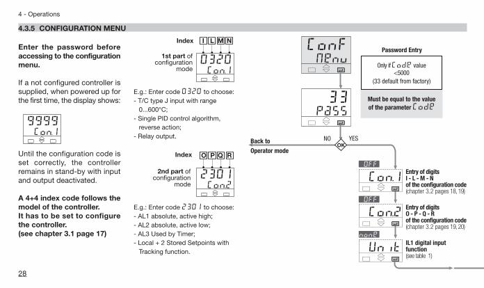
4.3.5 CONFIGURATION MENU
NO YES
Entry of digits I - L - M - N of the configuration code(chapter 3.2 pages 18,19)
Entry of digits O - P - Q - R of the configuration code(chapter 3.2 pages 19,20)
IL1 digital input function(see table 1)
Back to
Operator mode
Password Entry
Must be equal to the value of the parameter Code
Only if Code value<5000
(33 default from factory)
28
4 - Operations
Enter the password beforeaccessing to the configurationmenu.
If a not configured controller issupplied, when powered up forthe first time, the display shows:
Until the configuration code isset correctly, the controllerremains in stand-by with inputand output deactivated.
A 4+4 index code follows themodel of the controller. It has to be set to configurethe controller.(see chapter 3.1 page 17)
Con.19999
E.g.: Enter code 0320 to choose:- T/C type J input with range
0...600°C;- Single PID control algorithm,
reverse action;- Relay output.
E.g.: Enter code 2301 to choose:- AL1 absolute, active high;- AL2 absolute, active low;- AL3 Used by Timer;- Local + 2 Stored Setpoints with
Tracking function.
Index
1st part ofconfiguration
mode
I L M N
Con.10320
Index
2nd part ofconfiguration
mode
O P Q R
Con.22301
Q1 UK-ed3 7-04-2008 11:30 Pagina 28

sc.Hi
sc.dd
sc.lo
prot
baud
retr
rtH
Ht.f.s Code
rs.iné4=20
éM:bus
é9600
é4=20
ép:U:
é 33
29
4 - Operations
N° of decimals0…3
Low range -999…9999(min 100 digit)
High range -999…9999(min 100 digit)
Remote Setpointinput(see table 2)
CT primary highrangeOff/1…200 A
Communication protocolM.buS / jbuS
Baud rate1200/24004800/9600
Analogue controloutput range0=20 / 4=20mA
Control outputselectionP.U. / S.P.
LINEAR SCALEONLY
ANALOGUE OUTPUTOPTION OP5(if installed)
CT (only on propor-tional output other
than the servomotor)
REMOTE SETPOINT(if configured)
SERIAL COM.OPTION
(if installed)
Password 0…9999
33 default from factory
Back to the Con.1 parameter
Table 2 Remote Setpoint input typeérs:In
Value Description0=5 0…5 Volt1=5 1…5 Volt0=10 0…10 Volt0=20 0…20 mA4=20 4…20 mA
Table 1 Engineering units
none
éunit
none
Value Description
mU mV
°C degree centigrade°f degree Fahrenheit
U VoltmA mAA Amperebar BarpsI PSIrh Rhph pH
Q1 UK-ed3 7-04-2008 11:30 Pagina 29

A ALARM TYPE AND OPERATION CONDITIONS
30
4 - Operations
4.4 PARAMETERS
For a simpler use of the con-troller, its parameters have beenorganised in groups (menu),according to their functionalityarea.
The OP1, OP2 or OP3 outputs, canbe used for alarms if they are notused as control outputs It is possible to configure up to 4alarms: AL1, AL2, AL3, AL4 (seepage 19 and 20), selecting, foreach of them::A the type and the operating con-
dition of the alarm;B the functionality of the alarm
acknowledgement (latching)#ltch (see page 37);
C the start-up disabling (blocking)#bloc (see page 37);
D Loop break or sensor break (seepage 38).
AL1 alarm thresholdAL2 alarm thresholdAL3 alarm threshold
Alarm occurrences of OP1,OP2and OP3 outputs, respectivelylinked to AL1, AL2 and AL3.
The range of the alarm thresh-old correspond to the wholespan and it is not limited by theSP Setpoint span.
When the event occures, thedisplay will shows the redledsÅ, Ç or É, respec-tively on.
#A3s.P#A2s.P#A1s.P
Absolute alarm (full scale)OnOff
Activehigh
Activelow
hy
high rangelow rangeAlarm threshold
OnOff
Band alarmOnOff
Activeout
Activein
hy
SP
full scalefull scale
hy
alarm threshold
OnOff
Deviation alarmOnOff
Activehigh
Activelow
hy
+ high range- low rangeAlarm threshold
OnOff
SP
4.4.1 SETPOINT MENU
Q1 UK-ed3 7-04-2008 11:30 Pagina 30

When Remote Setpoint is con-figured, we suggest to disable#sl. u and #sl. d parametersOff.
31
4 - Operations
Setpoint ramp upSetpointramp down
This parameter specifies themaximum rate of change of theSetpoint in digit/min.
When the parameter is OFF,this function is disabled andthe new Setpoint is reachedimmediately after beingentered.
Otherwise, the Setpoint value isreached according to the con-figured rate of change.
The new Setpoint value is called"Target Setpoint". It can be dis-played by means the parameter#t.S.P.(see procedure at page 47).
#sl. d#sl. u Setpoint
low limitSetpoint high limit
Low / high limit of the Setpointvalue.
1st stored Setpoint2nd stored Setpoint
Preset Set values can be setfrom the keyboard and serialcommunication. The Setpointactive is indicated by the ú orù green led.
#S.P. 2#S.P. 1
#S.P. H#S.P. L If index r= 1 (tracking),
the previous Local Setpointvalue will be lost, when thestored Setpoint is selected.
If index r= 2 (Stand-by), the Local Setpoint value will notbe lost, when the Stand-bySetpoint is selected. It will oper-ate again when back to Local.
See stored Setpoint selectionprocedure at page 50
Setpointchange
Target Setpoint= 350°C
t t = 10
#sL. u = 10digit/minutes
Example
InitialSetpoint= 250°C
Q1 UK-ed3 7-04-2008 11:30 Pagina 31

32
4 - Operations
4.4.1 SETPOINT MENU
Remote Setpoint Bias and Ratio
bias = 20ratio = 0.1
ratio = –0.1
Remotesignal
Range600100200
RemoteSetpoint span
10V
bias = 100
a b
a´ b´
-200 °CHRa (b´ ) b (a´ )LR
If SR starting point is lower thenthe ending point, bothexpressed in engineering units:
biaS= starting point = a
rtio=
Example:biaS= 20rtio=
100 - 20600 - (-200)
80800
= 0.1=
b - aHR - LR
Remote Setpoint Ratio
Ratio is the coeff. which definesthe remote Setpoint span withrespect to the input span.
Remote Setpoint
Bias defines the starting point ofanalogue Remote Setpoint ineng. units corresponding to thelow limit (current or voltage) ofthe remote signal.
#bias
#rtio
PV = process variableLR = PV low limitHR = PV high limitSR = Remote Setpointa (a´) = SR starting pointb (b´) = SR ending point
Q1 UK-ed3 7-04-2008 11:30 Pagina 32

33
4 - Operations
If SR starting point is higherthen the ending point, bothexpressed in engineering units
biaS= starting point = a´
rtio=
Example:biaS= 100rtio=
20 - 100600 - (-200)
- 80800
= - 0.1=
b´ - a´
HR - LR
Working Setpoint (SP) as com-bination of Local Setpoint (SL)and remote signal
Setpoint type Loc.t(configuration index r= 4 )SP = SL + (rtio • REM)
+ biaS
Setpoint type reM.t (configuration index r= 5 )SP = REM + (rtio • SL)
+ biaS
SIGN = Remote signal percentage
SPAN = HR-LR
REM =SIGN * SPAN
100
Examples:Local Setpoint (SL) with anexternal Trim with multiplyingcoeff. of 1/10:Setpoint type = Loc.trtio= 0.1biaS= 0
Remote Setpoint (SR) with aninternal Trim with multiplyingcoeff. of 1/5:Setpoint type = reM.trtio= 0.2biaS= 0
Remote Setpoint range equal tothe Input range:Setpoint type = Loc.trtio = 1biaS= LRSL = 0
Q1 UK-ed3 7-04-2008 11:30 Pagina 33

34
4 - Operations
4.4.2 CONTROL MENU
275..0274.8
MenuCont
tunestrt
tunestop
Operatormode
press until
Control menu
To startselect strt
To stop select stop
STEP response
SP
End of the tuningoperating and setting of
the new calculatedterms.
Start of autotuneoperation
Setpoint change
PV variable
Control output
Natural frequency
PV variable
Control output
tuning start
End of the tuningoperating and settingof the new calculated
terms.
RunTune
4.4.2.1 AUTOMATIC TUNE
The Fuzzy-Tuning determinesautomatically the best PID termwith respect to the processbehaviour.
The controller provides 2 types of“one shot” tuning algorithm, thatare selected automatically accord-ing to the process condition whenthe operation is started.This type is selected when, at
#tune the start of the autotune oper-ation, the PV is far from theSetpoint of more than 5% of thespan. This method has the bigadvantage of fast calculation,with a reasonable accuracy inthe term calculation.
This type is selected when the PVis close to the SP Setpoint.This method has the advantageof a better accuracy in the termcalculation with a reasonablespeed calculation.
The Fuzzy Tuning determinesautomatically the best methodto use to calculate the PIDterm, according the processconditions.
FUZZY-TUNINGSTART/STOPPROCEDURE
Start/stop of the Fuzzy TuningThe Tuning operation can bestarted or stopped any time.
The green led Ä is ON whenthe Fuzzy Tuning is in progress.At the end of this operation, thecalculated PID terms parameterare stored and used by the con-trol algorithm and the controllergoes back to the operator mode.The green led Ä becomes off.
Q1 UK-ed3 7-04-2008 11:30 Pagina 34

35
4 - Operations
Proportional band
This parameter specifies the pro-portional band coefficient thatmultiplies the error (SP - PV)
Integral time
It is the integral time value, thatspecifies the time required by theintegral term to generate an out-put equivalent to the proportionalterm. When Off the integralterm is not included in the con-trol algorithm.
Derivativetime
It is the time required by the pro-portional term P to repeat theoutput provided by the deriva-tive term D. When Off thederivative term is not includedin the control algorithm.
#t.d.
#t.i.
#P.b. Overshoot control
This parameter specifies the spanof action of the overshoot control.Setting lower values (1.00 —> 0.01)the overshoot generated by aSetpoint change is reduced. Theovershoot control doesn’t affect theeffectiveness of the PID algorithm.Setting 1, the overshoot control isdisabled.
Manual Reset
This specifies the control outputvalue when PV = SP, in a PD onlyalgorithm (lack of the integralterm).
Error Dead Band
Inside this band for (PV - SP), the con-trol output does not change to pro-tect the actuator (output Stand-by):
#d.err
#M.res
#O.C. Control outputcycle timeCool cycle time
It’s the cycle time of the SSRdrive control output. The PIDcontrol output is provided by thepulse width modulation of thewaveform.
Control output high limitCool output high limit
It specifies the maximum valuethe control output can be set.It is applied in manual mode, too.
OutputSafety Value
Output Value in case of inputanomaly
#S.Out
#Op.C.H#Op. H
#t.c. C#t.c. Control output
hysteresisCool outputhysteresis#hy. C
#hy.
Control or alarm output hystere-sis span, set in % of the full scale.
Off
SPOn
hy
Q1 UK-ed3 7-04-2008 11:30 Pagina 35

36
4 - Operations
4.4.2 CONTROL MENU
4.4.2.2 HEAT / COOL CONTROL
By a sole PID control algorithm, the controllerhandles two different outputs, one of theseperforms the Heat action, the other one theCool action.
It is possible to overlap the outputs.
The dead band parameter #d.bnd, is the zonewhere it is possible to separate or overlapthe Heat and Cool actions.
The Cool action can be adjusted using therelative cool gain parameter #r.C.Ga.
To limit the Heat and Cool outputs the para-meters #0p. H and #0p.HC can be used.
When there is an overlap, the displayed out-put # OUt shows the algebric sum of theHeat and Cool outputs.
A Heat /Cool actions separatedInsert positive #d.bnd value (0…10%)
B Heat /Cool actions overlappedInsert negative #d.bnd value (-10…0%)
100%
100%
#d.bnd
#Op.HC#Op. H
50%
Heatcool
Cooloutput0%
0%PID output
-100%
100%
100%
#d.bnd
#Op.HC#Op. H
50%
Heatoutput
Cooloutput0%
0%PID output
-100%
C Cool action adjustingExample with different relative cool gains
D On-Off Cool action
100%
100%
#d.bnd
#hy. C
50%
Heatoutput
Cooloutput0%
0%PID output
On
Off
100%
100%
#d.bnd
#r.C.Ga 0.1…10.0
50%
Heatoutput
Cooloutput0%
0%PID output
-100%=2.0=1.0=0.5
Q1 UK-ed3 7-04-2008 11:30 Pagina 36
37
4 - Operations
4.4.3 AUXILIARY PARAMETERS MENU
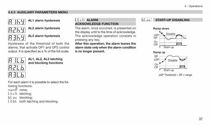
AL1 alarm hysteresis
AL2 alarm hysteresis
AL3 alarm hysteresis
Hysteresis of the threshold of both thealarms, that activate OP1 and OP2 controloutput. It is specified as a % of the full scale.
AL1, AL2, AL3 latching and blocking functions
For each alarm it is possible to select the fol-lowing functions:none none;Ltch latching;bloc blocking;Lt.bL both latching and blocking.
#AIL.b#A2L.b#A3L.b
#A3hy#A2hy#AIhy #Ltch ALARM
ACKNOWLEDGE FUNCTIONThe alarm, once occurred, is presented onthe display until to the time of acknowledge.The acknowledge operation consists inpressing any key.After this operation, the alarm leaves thealarm state only when the alarm conditionis no longer present.
#bloc START-UP DISABLING
DisableSP∆SP
OnOff
Start-up
∆SP Disable
SP
OnOff
Start-up
Ramp down
Ramp up
∆SP Threshold = SP ± range
Q1 UK-ed3 7-04-2008 11:30 Pagina 37

38
4 - Operations
4.4.3 AUXILIARY PARAMETERS MENU
ALARMS WITH LBA (LOOP BREAK ALARM) AND SENSOR BREAK OPERATION Selecy the code 1 on o, p or q configuration indexes (seepages 21 or 22). The following parameter is then available:
LBA delay#t.lbaSetting a value between 1 and9999 s the alarm works asLBA+Sensor break with delay[1].This condition is shown bymeans a red led as well as theblinking PV display:
Setting OFF the alarm worksas Sensor break with immedi-ate action.This condition is shown bymeans the red led of the select-ed alarm as well as:
When the cause of the alarm disappears, the alarm status stops.
275.01 2 3
274.8
mA
°C
OP1
or275.01 2 3
8888275.0
1 2 3
8888____ ----
Soft-startcontrol output value
Value of the control output dur-ing the Soft-start activation time.
Soft-startactivation time
Time duration (starting from thepower on) of the Soft-start func-tion.
Soft-start
100%
Power on
#St.tM
#St.OP
OP
Time
#st.tM
#st.Op Input filter time constant
Time constant, in seconds, of theRC input filter applied to the PVinput.When this parameter is set toOff the filter is bypassed.
Input shift
This value is added to the mea-sured PV input value. Its effect isto shift the whole PV scale of upto ± 60 digits.
#In.sh
Filter response100%
0
PV63,2%
t.Fil Time
#t.fil
Note [1] In case of sensor break,condition, the alarm action is imme-diate.
Q1 UK-ed3 7-04-2008 11:30 Pagina 38
39
4 - Operations
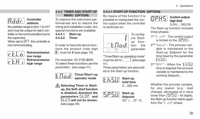
4.4.4.1 START-UP FUNCTION (OPTION)By means of this function it ispossible to manipulate the con-trol output when the controlleris switched on.
To config-ure Start-up func-tion theparameter
“Timer/Start-up operating mode”must be set to # 1 (see page41).Three parameters are associat-ed to the Start-up function.
Start-up hold time0…500 min
Start-up Setpoint(S.P. L…S.P. H)
#S.P.s.U
#t.h.s.U
t.Mod 1
Control outputhigh limit5.0%…100.0%
The Start-up function includesthree phases:
1st “Limy” - The control outputis limited to the #Op.Hs ;
2nd “Hold” - The process vari-able is maintained to theStart-up Setpoint for thetime fixed by the parameter#t.h.s.U ;
3rd “Off” - When the #t.h.s.Utime is elapsed the processvariable is maintained to theworking Setpoint.
Whether the process variable,for any reason (e.g.: loadchange), decreases at a valuelower than ( #s.p.sU - 40 digits),the Start-up function starts againfrom the “Limy” phase.
#Op.HsController address
the address range is from 1 to 247and must be unique for each con-troller on the communication bus tothe supervisor. When set to Off the controller isnot communicating.
Retransmissionlow rangeRetransmissionhigh range#rt.Hi
#rt.lo
#Addr
4.4.4 TIMER AND START-UP MENU (OPTION)
To improve the instrument per-formances and to reduce thewiring and installation costs, twospecial functions are available:4.4.4.1 Start-up4.4.4.2 Timer
In order to have the above func-tions the product code digitemust be 2 (see page 19).
For example: X3 3100-2000To select these functions use theparameter: (see page 41).
Timer/Start-upoperator mode
A Selecting Timer or Start-up, the Soft-start functionis disabled, therefore theparameters #st.Op and#st.tM will not be shown.(see page 29).
#t.Mod
Q1 UK-ed3 7-04-2008 11:30 Pagina 39

40
4 - Operations
When the Start-up is in Holdphase, if the local Setpointbecomes lower than the Start-up Setpoint or if the operatingmode changes to manual, theStart-up function passes to the“Off” phase.
There are two possibilities:A Start-up Setpoint #sp.sU
lower than the localSetpoint.The “Hold” phase startswhen the process variablePV achieves the #sp.sU(with a tolerance of 1 digit).
B Start-up Setpoint #sp.sUgreater than or equal tothe local Setpoint.
When the process variable PVachieves the local Setpoint (with atolerance of 1 digit), the Start-upfunction passes directly to the “Off”phase.
If, at the controller power-on, theprocess variable PV is greater thanthe lowest between the #sp.sUand the working Setpoint , thenext phase (“Hold” or “Off”) willbe executed instead of the “Limy”phase.
Dur ing the “Limy” and“Hold” phases the Ö led ison.
4201285
RUN
Start-upSetpoint
A #s.P.sU < local Setpoint SP
B #s.P.sU ≥ Setpoint locale SP
noise Setpoint SP
PV
40 digit
1 digit#t.h.S.U #t.h.S.U#S.P.S.U
Power-on
OP=OP.H5with TC = 25%1s min.
1st “Limy” 2nd “Hold” 3rd “Off” 1st “Limy” 2nd “Hold” 3rd “Off”
noiseSetpoint SP
PV
40 digit
1 digit
#s.p.s.UPower-on
OP=OP .H5with TC = 25%1s min.
1st “Limy” 3rd “Off” 1st “Limy” 3rd “Off”
4.4.4.1 START-UP FUNCTION (OPTION)
Q1 UK-ed3 7-04-2008 11:30 Pagina 40

41
4 - Operations
4.4.4.2 TIMER FUNCTION (OPTION)
AThe Timer can’t beenabled with Heat / Coolcontrol.
To enable this function do the fol-lowing:1 In order to use this AL3 func-
tion, index qmust be set to0 in configuration (see p. 20);
2 To select one of the 6 possi-ble functioning modes of theTimer, set the value of the 2following parameters in para-meterisation (see p. 27).
Timer Action
By this parameter can bedefined(see table 2):- the time units;- the starting mode;- the OP3 status when the timer
is running.When the timer is not running, theOP3 takes the opposite status.
#t.Act Timer setting
(1…9,999 s/min.)
Stand-by Setpoint
(only for t.Mod = 7)(S.P. L…S.P. H)
#S.P.sb
#tiMe
Timer/Start-up counting mode Value
Countingstart time
End mode
When inside theband
Control mode 2Output to 0 3
When launched Control mode 4Output to 0 5
When launched.Control disabled Control mod 6
When launchedstand-by Setpoint Control mod 7
table 1
table 2
Timeunits
Starting mode
[1]OP3
statusValue
Seconds
Manual bykeypad
Off 0On 1
Auto at power on [2]
Off 2On 3
Minutes
Manual bykeypad
Off 4On 5
Auto at power on [2]
Off 6On 7
[1] If used by Timer;[2] Using this selection, manual
starting mode is possible too.Now the other parameter valuescan be entered:
Timer/Start-upoperating mode
By this parameter can be defined(see table 1):- the counting start time;- the control output status at the
end of the counting.
#t.Mod
Disabled OFFStart-up function 1
Q1 UK-ed3 7-04-2008 11:30 Pagina 41

42
4 - Operations
TIMER COUNTING MODES
A - Counting start time inside the band,end in control mode.
The time counting starts only when the erroris inside a ± 1 digit band. The control actionis not affected by the Timer function.
C - Counting start time = timer launchtime, end in control mode.
The time counting starts when the timer islaunched. The control action is not affectedby the Timer function.
B - Counting start time inside the band,end with control output forced to zero.
The time counting starts only when the erroris inside a ± 1 digit band. At the end, the con-trol output is forced to zero [1].
#tiMeTimer launch
Setpoint
Processvariable PV
Output OP
OP3
±1 digitband
#t.Mod = 2 #tiMeTimer launch
Setpoint
Processvariable PV
Output OP
OP3
±1digitband
#t.Mod =3 #tiMeTimer launch
Setpoint
Processvariable PV
Output OP
OP3
#t.Mod = 4
Note:[1] When the Timer is not running the con-trol output is forced to zero, also before theTimer launch
4.4.4.2 TIMER FUNCTION (OPTION)
Q1 UK-ed3 7-04-2008 11:30 Pagina 42

TIMER COUNTING MODES
43
4 - Operations
D - Counting start time = timer launch time,end with control output forced to zero.
The time counting starts when the timer islaunched. At the end, the control output isforced to zero [1].
F - Control action with stand-by Setpointduring the counting time
The time counting starts when the timer islaunched and the control action use theStand-by Setpoint. At the end, the controlaction use the working Setpoint.
E - No control action during the counting time.
The time counting starts when the timer islaunched and the control output is forced tozero. At the end, the control action starts.
#tiMeTimer launch
Setpoint
Processvariable PV
Output OP
OP3
#t.Mod = 5#tiMe
Timer launch
Setpoint
Processvariable PV
Output OP
OP3
#t.Mod = 6 #tiMeTimer launch
Setpoint
Processvariable PV
Output OP
OP3
#s.p. 2
#t.Mod =7
Note:[1] When the Timer is not running the con-trol output is forced to zero, also before theTimer launch.
Q1 UK-ed3 7-04-2008 11:30 Pagina 43
44
4 - Operations
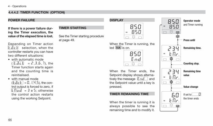
If there is a power failure dur-ing the Timer execution, thevalue of the elapsed time is lost.
Depending on Timer action#t .act selection, when thecontroller restarts you can havetwo different situations:• with automatic mode
( #t .act = 2,3,6,7), theTimer function starts againand the counting time isreinitialised.
• with manual mode ( #t.act = 0,1,4,5), the con-trol output is forced to zero, if#tMod = 3 e 5; otherwisethe control action restartsusing the working Setpoint.
TIMER STARTING
See the Timer starting procedureat page 49.
DISPLAY
When the Timer is running, theled Ö is on.
When the Timer ends, theSetpoint display shows alterna-tively the message #End andthe Setpoint value until a key ispressed.
TIMER REMAINING TIME
When the timer is running it isalways possible to see theremaining time and to modify it.
End 850
850 850
RUN
POWER FAILURE
850 850
RUN
tM.r. 60
RUN
tM.r. 234
RUN
tM.r. 234
RUN
Operator mode and Timer running
Press until
Remaining time.
Counting stop.
Remaining timevalue
Value change
If set to # 0the timer ends
4.4.4.2 TIMER FUNCTION (OPTION)
Q1 UK-ed3 7-04-2008 11:30 Pagina 44

45
4 - Operations
With CT option, it is possible todisplay the load current and setan alarm threshold.
The setting can be done bymeans the 8 or 9 configurationindex of the codes O, P or Q(see pages 19 and 20).It is possible to set one of thealarms (see pages 19 and 20) tohave an alarm when, during theON time of the time proportion-al output, the load current is lessthen the specified threshold(index 8), or during the OFFtime there is a value > 3% of fullscale load current.
The alarm condition must belonger than 120 ms to set thealarm.By the parameter:
CT primary high rangeOFF/ 1…200A
the load current display can beadapted to the transformer char-acteristics. (OFF means disabled).
During the OFF time the para-meter #t.Cur latches the last ontime current value.
#Ht.f.S
CURRENT TRANSFORMER INPUTWhen OP5 output is present itretransmits linearised PV or SP. On configuration (see page 29)it is possible to set:
Output range0=20 / 4=20Retransmitted signalnone P.U. / S.P.
The following parameters definethe low and high range of theOP5 retransmission output cor-responding to 0…4mA or 20mA (see page 27):
Retransmission low range
Retransmission high range#rt.Hi
#rt.lo
#rtH
#retr
RETRANSMISSION
4.4.5 CONFIGURATION MENU
Example:• T/C S, range 0…1600°C;• Output range, 4…20 mA;• Retransmitted signal PV on
800…1200°C range.
20
4
800 1200 1600
#retr = 4=20#rt.H = P.U.#rt.Lo = 800#rt.Hi =1200
mA
°C
With rt.lo greater thanrt.hi it is possible to obtaina reverse scale.
Q1 UK-ed3 7-04-2008 11:30 Pagina 45

46
4 - Operations
Communication protocolM.bus/ j.bus
Baud rate1200/ 24004800/ 9600
#baud
#prot
SERIAL COMMUNICATIONS
Example:CT input on OP1, alarm on AL2 during on time (configuration digitp = 8, see page 19).
ON ON
ON ON
3%
A2s.p
t.Cur
120 ms 120 ms
OFFOP1
AL2 OFF OFF OFF
Load
cur
rent
CURRENT TRANSFORMER INPUT
4.4.5 CONFIGURATION MENU
Q1 UK-ed3 7-04-2008 11:30 Pagina 46

5.1 OF THE PROCESS VARIABLES 5.2 OF THE CONFIGURATION CODES
47
5 - Displays
5 DISPLAYS
274.8 °C
275.0S.P.
63.4Out
380.0t.S.P.
47t.Cur
33tM.r.
275.0274.8
274.8 °C
2002Con.1
2321Con.2
00AreL.
3150Hard
275..0274.8 Engineering
units(see table 2 page 29)
Basic product code (Hardware page 17)
1st part of the configuration code(see pages 18 and 19)
2nd part of the configuration code(see pages 18 and 19)
OP1 outputPID only
Local Setpoint
modifiable value
Timer remaining time
modifiable value(if option installed,
see page 44)
Target Setpoint valuelocal mode only(not displayed if theSlopes are disabled)
Load current in Ampere(CT option only,see page 45)
Software release
Operatormode
Operatormode Engineering
units (see Table 2 page 29)
Manual AUTO
Q1 UK-ed3 7-04-2008 11:30 Pagina 47

48
6 - Commands
COMMANDS TO THE CONTROLLER AND OPERATING PHASES6 COMMANDS
The commands can beentered in 2 ways:
6.1 KEYPADsee page 49
• Setpoint modification;• Timer start;• Local/remote selection;• Stored Setpoint display;• Keypad lock;• Outputs lock.
6.2 SERIAL COMMUNICATIONS
see the manual on this topic
Q1 UK-ed3 7-04-2008 11:30 Pagina 48

49
6 - Commands
6.1 KEYPAD COMMANDS
The Setpoint is directly modifiedwith the $%keys.Once entered, the new value ischecked and becomes operatingafter 2 seconds. The end of thisphase is flagged by flashingmomentarily the display with SP.
6.1.1 SETPOINT MODIFICATION 6.1.2 TIMER STARTING (option)
Operator mode
Example of Setpointmodification from275 to 350
Modified Setpoint value
Flash momentarilythe SP value to con-firm that it hasbecome operating.back to the operatormode
after 2 seconds
274.8275.0
274.8350.0
274.8350.0
Depending on the Timer action#t.act selection, there can betwo different starting ways:- Automatic at the power on- Manual by keypad, digital
inputs or serial communica-tions.
350 350
t.runstop
t.runstrt
Operatormode
Press until
To startselect strt
To stopselect stop
Press the key è to confirm
To start/stop the Timer:
Q1 UK-ed3 7-04-2008 11:30 Pagina 49

274.8275.0
S.P. 1S.Sel
LocS.Sel
S.P. 2S.Sel
noneS.Sel
S.P. 1S.Sel
S.P. 2S.Sel
50
6 - Commands
6.1.3 LOC/ REM SELECTIONconfiguration index r= 4 or 5)
6.1.4 STORED SETPOINTS SELECTION(configuration index r = 1 or 2)
The selected Setpoint becomes operatingpressing the è
When in Remote, the green led Ü is on
The selected Setpoint becomesoperating pressing the
è key.
The corrispondig green led(ú or ù) is on
Operatormode
Press until Press until
Select reMto enable Remote Setpoint
Select Locto enable Local Setpoint
Select S.P.1 to forcethe first Setpoint
Select S.P.2 to forcethe second Setpoint
Select none to free theSetpoint modification, then
Press $% to changethe local Setpoint
Select Loc to come back tothe previous local Setpoint value
274.8275.0
Loc L=r
reM L=r
TrackingIndex r = 1
Stand-byIndex r = 2
6.1 KEYPAD COMMANDS
Q1 UK-ed3 7-04-2008 11:30 Pagina 50

51
6 - Commands
To lock/unlock the keypad pressthe keys í and è simulta-neously for 2 seconds.To confirm the keypad lock/unlock the display flashes once.
The keypad lock/unlock can beachieved by serial communica-tions too.
AThe keypad lock is main-tained in case of powerfailure.
The outputs are switched to theOFF status by pressing the keysí and %together.When the outputs are locked ,the message #Off is displayedinstead of the Setpoint value.To unlock the outputs pressagain the keys simultaneously (the Soft-start will be enabled).
The outputs lock/unlock canbe achieved by serial com-munications too.
AThe outputs lock/unlockis maintained in case ofpower failure.
6.1.5 KEYPAD LOCK 6.1.6 OUTPUTS LOCK
Q1
SP
PV
45.8045 .80
Q1
SP
PV
45.8045 .80
operator mode
Press simultaneouslyfor 2 seconds
operator mode
Press simultaneouslyfor 2 seconds
Q1 UK-ed3 7-04-2008 11:30 Pagina 51

52
7 - Technical specifications
7 TECHNICAL SPECIFICATIONS
Total configurability(see chapter 3.2 page 18
chapter 4.3.5 page 28)
PV Input(see pages 11,12 and page 18)
Features(at 25°C environmental temp.) Description
From keypad or serial communication the user selects:- the type of input - the type and functionality of the alarms- the type of control algorithm - the type of Setpoint- the type of output - control parameter values
Common characteristics
A/D converter with resolution of 50,000 pointsUpdate measurement time: 0.2 secondsSampling time: 0.5 secondsInput bias: - 60…+ 60 digitInput filter with enable/disable: 1…30 seconds
Accuracy 0.25% ±1 digits for temperature sensors0.1% ±1 digits (for mV and mA)
Between 100…240Vacthe error is minimal
Resistance thermometer(for ∆T: R1+R2 must be <320Ω)
Pt100Ω at 0°C(IEC 751)°C/°F selectable
2 or 3 wires connectionBurnout (with any combination)
Max. wire Res: 20Ω max. (3 wires)Input drift: 0.35°C/10°C Tenv.<0.35°C/10Ω Wire Res.
Thermocouple
L,J,T,K,S, R, B, N, E, W3, W5(IEC 584)Rj >10MΩ°C/°F selectable
Internal cold junction compensation con NTCError 1°C/20°C ±0.5°C Burnout
Max.wire Res.: 150Ω max.Input drift: <2µV/°C Tenv.
<5µV/10Ω Wire Res.
DC input (current)4…20mA, 0...20mAwith external shunt 2.5ΩRj >10MΩ
Burnout. Engineering unitsConf. decimal point positionInit. Scale -999…9,999Full Scale -999…9,999(min. range of 100 digits)
Input drift: <0.1%/20°C Tenv.
DC input (voltage) 10…50mV, 0...50mVRj >10MΩ
Q1 UK-ed3 7-04-2008 11:30 Pagina 52

53
7 - Technical specifications
Features(at 25°C environmental temp.) Description
Auxiliary inputs
Remote Setpoint (option)Not isolatedaccuracy 0.1%
Current0/4…20mARj = 30Ω Bias in engineering units and ±range
Ratio from -9.99…+99.99Local + Remote SetpointVoltage
1...5/0...5/0...10VRj = 300kΩ
CT current transformer(see pages12 and 45)
50 or 100 mAinput hardwareselectable
Current visualisation 1...200AWith 1A resolutionand Heater Break Alarm
Operating mode and Outputs
1 single or double actionPID loop orOn/Off with 1, 2 or 3 alarms
Control output
Single action
AL1 alarm AL3 alarm
OP1-Relay/Triac
OP1-Relay/Triac OP2-Relay/Triac
Double actionHeat / Cool
AL2 alarm Retransmiss.
OP2-Relay/Triac
OP3-Relay
OP3-Relay
OP5-Analogue
OP5-Analogue
OP4-SSR drive/Relay OP1-Relay/Triac OP2-Relay/Triac OP3-Relay OP5-Analogue
OP4-SSR drive/Relay
OP1-Relay/Triac
OP2-Relay/Triac
OP4-SSR drive/Relay
OP1-Relay/Triac
OP2-Relay/Triac
OP3-Relay
OP3-Relay
OP5-Analogue
OP5-Analogue
Q1 UK-ed3 7-04-2008 11:30 Pagina 53

54
7 - Technical specifications
Features(at 25°C environmental temp.) Description
Control mode
Algorithm PID with overshoot control or On-off - PID with valve drive algorithm, for controlling motorised positioners
Proportional band (P) 0.5…999.9%
Integral time (I) 0.1…100.0 min
Derivative time (D) 0.01…10.00 min
Error dead band 0.1…10.0 digit
Overshoot control 0.01…1.00
Manual reset 0.0…100.0%
Cycle time (Time proportional only) 1…200 s
Control output high limit 10.0…100.0%
Soft-start output value 0.1…100.0%
Output safety value 0.0…100.0% (-100.0…100.0% for Heat / Cool)
Control output hysteresis 0.1…10.0% On-Off algorithm
Dead band -10.0…10.0%
Double action PID algorithm (Heat / Cool) with overlap
Relative cool gain 0.1…10.0
Cycle time (Time proportional only) 1…200 s
Control output high limit 10.0…100.0%
Cool output hysteresis 0.1…10.0%
Single actionPID algorithm
OFF = O
OFF = O
Q1 UK-ed3 7-04-2008 11:30 Pagina 54

55
7 - Technical specifications
Features(at 25°C environmental temp.) Description
OP1-OP2 outputsSPST Relay N.O., 2A/250Vac (4A/120Vac) for resistive loadTriac, 1A/250Vac for resistive load
OP3 output SPDT relay N.O., 2A/250Vac (4A/120Vac) for resistive load
OP4 output SSR drive: 0/5Vdc, ±10% 30mA max. - SPST Relay N.O., 2A/250Vac (4A/120Vac) for resistive load
OP5 analogue output(option)
Control or PV/SPretransmission
In current: 0/4…20mA, 750Ω / 15V max.
AL1 - AL2 - AL3alarms
Hysteresis 0.1…10.0% c.s.
Action
Active highAction type
Deviation threshold ±range
Band threshold 0…range
Absolute threshold whole range
Special functions
Sensor break, heater break alarm
Acknowledge (latching), activation inhibit (blocking)
Connected to Timer or program (if options installed)
Setpoint
Local
Up and down ramps 0.1…999.9 digit/min (OFF=0) Low limit: from low range to high limitHigh limit: from low limit to high range
Local
Local and Remote
Local with trim
Remote with trim
Galvanic isolation: 500 Vac/1 minResolution 12 bit (0.025%)Accuracy: 0.1 %
Active low
If option installed
Q1 UK-ed3 7-04-2008 11:30 Pagina 55

56
7 - Technical specifications
Features(at 25°C environmental temp.) Description
Fuzzy-Tuning one shootThe controller selects automatically the best method according to the process conditions
Step responseNatural frequency
Special functions(option)
Timer (see page 41)
Serial comm. (option) RS485 isolated, Modbus/Jbus protocol, 1,200; 2,400; 4,800; 9,600 bit/s 3 wiresAuxiliary Supply +24Vdc ±20% 30mA max. - for external transmitter supply
Operational safety
Measure inputControl outputParametersAccess protection
General characteristics
Power supply(PTC protected)Safety
UL and cUL approval
Electromagnetic compatibility
Protection EN60529 (IEC529)
Automatic start at the power on, manual start by keypad, Digital inputs or serial comm.s
Control output high limit: 5.0…100.0%Hold time: 0… 500 minStart-up Setpoint: from Setpoint low limit to Setpoint high limitStand-by Setpoint: from Setpoint low limit to Setpoint high limitSetting time: 1…9,999 s/min
Start-up (see page 39)
Parameter and configuration data are stored in a non volatile memory for an unlimited timeSafety value: -100%…100%Detection of out of range/short circuit/sensor break with automatic activation of safety strategies and alerts on display
Password to access the configuration and parameters data, keypad lock, outputs lock
100...240Vac (-15...+10%) 50/60 Hz or 24Vac (-25...+12%) 50/60Hz e 24Vdc (-15...+25%)Compliance to EN61010-1 (IEC 1010 – 1), installation class 2 (2.5kV) pollution class 2, instrument class II
Compliance to the CE standards (see page 2)
File 176452
IP65 front panel
Power consumption 4W max.
1/4 DIN - 96 x 96, depth 110 mm, weight 470 g approx.Dimensions
Q1 UK-ed3 7-04-2008 11:30 Pagina 56

57
Warranty
1 WARRANTY
We warrant that the products willbe free from defects in material andworkmanship for 3 years from thedate of delivery.The warranty above shall not applyfor any failure caused by the use ofthe product not in line with theinstructions reported on this manual.
Q1 UK-ed3 7-04-2008 11:30 Pagina 57

58
ASCON’S WORLDWIDE SALES NETWORK
FRANCEASCON FRANCE
2 bis, Rue Paul Henri SpaakST. THIBAULT DES VIGNESF-77462 LAGNY SUR MARNE - CedexTél. +33 (0) 1 64 30 62 62Fax +33 (0) 1 64 30 84 [email protected]
AGENCE SUD-EST
Tél. +33 (0) 4 74 27 82 81Fax +33 (0) 4 74 27 81 71
USAASCON CORPORATION
1884, East Fabyan ParkwayBatavia, Illinois 60510Tél. +1 630 482 2950Fax +1 630 482 [email protected]
ARGENTINAMEDITECNA S.R.L.Phone +5411 4585 7005Fax +5411 4585 3434
AUSTRALIAIPA INDUSTRIAL PYROMETER (AUST) PTY.LTDPhone +61 8 8352 3688Fax +61 8 8352 2873
FINLAND & ESTONIATIM-TOOL OY
Phone +358 50 501 2000Fax +358 9 50 55 144
GERMANYMESA INDUSTRIE ELEKTRONIK GMBHPhone +49 2365 915 220Fax +49 2365 915 225
GREECECONTROL SYSTEM
Phone +30 31 521 055-6 Fax +30 31 515 495BRANCH OFFICE
Phone +30 1 646 6276Fax +30 1 646 6862
HOLLANDHSD INSTRUMENTS
Phone +31 78 617 03 55Fax +31 78 618 26 68
PORTUGALREGIQUIPAMENTOS LDAPhone +351 21 989 0738Fax +351 21 989 0739
SPAININTERBIL S.L.Phone +34 94 453 50 78Fax +34 94 453 51 45BRANCH OFFICE
Phone +34 93 311 98 11 Fax +34 93 311 93 65 Phone +34 91 656 04 71Fax +34 91 677 21 26
SWITZERLANDCONTROLTHERM GMBHPhone +41 1 954 37 77Fax +41 1 954 37 78
TURKEY KONTROL SISTEMLERI LTDPhone +90 216 302 19 70-71Fax +90 216 302 19 72
UNITED KINGDOMEUKERO CONTROLS LTDPhone +44 20 8568 4664Fax +44 20 8568 4115
DISTRIBUTORSSUBSIDIARY
Q1 UK-ed3 7-04-2008 11:30 Pagina 58

59
Icons table
Main universal input Digital input
Thermocouple Isolated contact
RTD (Pt100) NPN open collector
Delta Temp (2x RTD) TTL open collector
mA and mVSetpoint
Custom Local
Frequency Stand-by
Auxiliary inputKeypad lock
Current transformer Outputs lock
mA Remote setpoint Start-up function
Volt Remote setpoint Timer function
Feedback potentiometer
Memorized
Remote
Setpoint programmer
Logic
mA mV
mA
SPDT Relay
Triac
SPST Relay
Output
Setpoint slopes inhibition
PV hold
Run, Hold, Reset andprogram selection
Auto/Manual
Digital input connected functions
ICONS TABLE
Q1 UK-ed3 7-04-2008 11:30 Pagina 59

60
Q1 UK-ed3 7-04-2008 11:30 Pagina 60