Q QUICK UICK HIP CCONVEYORS ONVEYORS - Quick Ship … · HIP. CCONVEYORS. ONVEYORS. ... conveyor...
38
ArrowSelect ® ArrowSelect ® Technical Manual Q Q UICK UICK S S HIP HIP C C ONVEYORS ONVEYORS
Transcript of Q QUICK UICK HIP CCONVEYORS ONVEYORS - Quick Ship … · HIP. CCONVEYORS. ONVEYORS. ... conveyor...
ArrowSelect®
Arrow
Sele
ct®
Tech
nic
al M
an
ual
QQUICKUICK SSHIPHIP
CCONVEYORSONVEYORS


ArrowSelect® Technical Manual When you need to add or replace a component or section of your product handling system, ArrowSelect® can SAVE COSTS... in dollars and time.
The ArrowSelect® Concept
ArrowSelect® can streamline your new conveyor configuration – whether your system faces upgrades due to new contracts or changes in product design.
ArrowSelect® allows you to...
• Select pre-manufactured components or conveyor sections in the easy-to-use ArrowSelect® Technical Manual.
• Order your new components or sections by calling the ArrowSelect® hotline at 920-235-5562.
• Receive your order in 1/3 the time it would take to receive a custom order.
• Install the new components using your own personnel, saving installation costs.
We stock most standard components and conveyor sections, allowing us to ship your order without delay – typically within two weeks or less.
Questions? Call the ArrowSelect Hotline...
920-235-5562
The ArrowSelect® Promise
ArrowSelect® offers you an entire family of both table top and mat top conveyors and complementary products for your product handling system.
ArrowSelect® assures you of...
• Quick Delivery
We maintain an inventory with standard conveyor components so we can respond rapidly to your needs.
• Optimum Quality
ArrowSelect® components and sections have been designed and precision engineered for layout flexibility, easy installation, and long term reliability.
• Maximum Value
Arrowhead purchases in large volume so we can produce conveyor components and sections at LOW cost... and pass the savings on to you.
In Stock Components The key to ArrowSelect® is Arrowhead Conveyor’s complete inventory of finished components.
• Each component is manufactured to exact tolerances and inspected before being placed in inventory.
• When you order ArrowSelect®, we immediately respond to your needs by assembling and shipping a finished product of utmost quality.
Becca
Rectangle
Becca
Rectangle
Becca
TextBox
Arrow Conveyor Equipment Inc. at 585-377-7115
Becca
Rectangle

Page 3 of 37
Table of Contents Table of Contents ................................................................................................................................. 3
ArrowSelect® Table Top Conveyors ................................................................................................... 5 Table Top General Specifications ....................................................................................................... 5
1) Material ......................................................................................................................................................... 5 2) Chain Types .................................................................................................................................................. 5 3) Open Top Construction ................................................................................................................................. 5 4) Wearstrips UHMW ........................................................................................................................................ 5 5) Chain Return ................................................................................................................................................. 5 6) Bearings ........................................................................................................................................................ 5 7) Supports ........................................................................................................................................................ 5 8) Guide Rail Brackets ...................................................................................................................................... 6 9) Guide Rails ................................................................................................................................................... 6 10) Motor Mount ................................................................................................................................................ 6 11) Drive Package for standard flange mounted drive ..................................................................................... 6 12) Drive Package for Optional Under slung mounted drive ............................................................................ 6
Table Top Engineering / Application ................................................................................................... 7 Drive Construction .............................................................................................................................................. 7 Idle Construction ................................................................................................................................................ 8 Turn Construction ............................................................................................................................................... 8 Intermediate Construction .................................................................................................................................. 8 Parallel Transfer Construction ........................................................................................................................... 9 Inline Transfer Construction ............................................................................................................................... 9 Adjustable Cope Construction ......................................................................................................................... 10 Transfer Plate Construction ............................................................................................................................. 10
Table Top General Information ......................................................................................................... 11 Table Top Chain Selection ............................................................................................................................... 11 Chain and Product Compatibility Guide ........................................................................................................... 11 Guide Rail Settings (Round Product) ............................................................................................................... 12 Conveyor Speeds ............................................................................................................................................. 12
Table Top Chain Types and Dimensions .......................................................................................... 13 LF820 Chain (Straight) ..................................................................................................................................... 13 LF821 Chain (Straight) ..................................................................................................................................... 13 LF831 Chain (Straight) ..................................................................................................................................... 13 SS815 Chain (Straight) .................................................................................................................................... 14 LF879TAB Chain (Curve) ................................................................................................................................ 14 LF880TAB Chain (Curve) ................................................................................................................................ 14 LF882TAB Chain (Curve) ................................................................................................................................ 15 SS881TAB Chain (Curve) ................................................................................................................................ 15
Table Top Standard Cross-Section Styles and Dimensions .............................................................. 16 Straight Returns ............................................................................................................................................... 16 Curve Returns .................................................................................................................................................. 17
Page 4 of 37
ArrowSelect® Mat Top Conveyors..................................................................................................... 18 Mat Top General Specifications ........................................................................................................ 18
1) Material ....................................................................................................................................................... 18 2) Chain Types ................................................................................................................................................ 18 3) Open Top Construction ............................................................................................................................... 18 4) Wearstrips UHMW ...................................................................................................................................... 18 5) Chain Return ............................................................................................................................................... 18 6) Bearings ...................................................................................................................................................... 18 7) Supports ...................................................................................................................................................... 18 8) Guide Rail Brackets .................................................................................................................................... 19 9) Guide Rails ................................................................................................................................................. 19 10) Motor Mount .............................................................................................................................................. 19 11) Drive Package........................................................................................................................................... 19
Mat Top Engineering / Application .................................................................................................... 20 Drive Construction ............................................................................................................................................ 20 Idle ConstructioN .............................................................................................................................................. 20 Intermediate Construction ................................................................................................................................ 21 90° Transfer Construction ................................................................................................................................ 21 Adjustable Cope Construction ......................................................................................................................... 22 Transfer Plate Construction ............................................................................................................................. 22 Parallel Transfer Construction ......................................................................................................................... 23
Mat Top General Information ............................................................................................................ 24 Mat Top Chain Selection .................................................................................................................................. 24 Chain and Product Compatibility Guide ........................................................................................................... 24 Guide Rail Settings (Round Product) ............................................................................................................... 25 Conveyor Speeds ............................................................................................................................................. 25
Mat Top Chain Types and Dimensions ............................................................................................. 26 HP8505 MTW Chain ........................................................................................................................................ 26 HP8505 Standard Chain .................................................................................................................................. 27 HP8506 MTW Chain ........................................................................................................................................ 28 HP8506 Standard Chain .................................................................................................................................. 29
Mat Top Standard Cross-Section Styles and Dimensions ................................................................. 30 325 Returns ...................................................................................................................................................... 30 450 Returns ...................................................................................................................................................... 31 750 Returns ...................................................................................................................................................... 32 1200 Returns .................................................................................................................................................... 33 1500 Returns .................................................................................................................................................... 34 1800 Returns .................................................................................................................................................... 35 2400 Returns .................................................................................................................................................... 36
© 2013 Arrowhead Systems, Inc. All rights reserved.

ArrowSelect® Table Top Conveyors Page 5 of 37
ARROWHEAD CONVEYOR CORPORATION • 3255 MEDALIST DR. OSHKOSH, WI 54902 USA • 920-235-5562 • WWW.ARROWHEADSYSTEMS.COM
ArrowSelect® Table Top Conveyors Table Top General Specifications
1) MATERIAL
• 10 gauge #4 polish type 304 stainless steel side frames
• 10 gauge mild steel frames painted Burke Superlife 316 SS Flake
2) CHAIN TYPES
Straight Flex LF820 - K3¼ LF879T - K3¼
LF820 - K4½ LF879T - K4½
LF820 - K7½ LF880T - K3¼
LF821 - K7½ LF880T - K4½
LF821 - K10 LF882T - K4½
LF821 - K12 LF882T - K7½
LF831 - K3¼ LF882T - K10
LF831 - K4½ LF882T - K12
LF831 - K7½ SS881T - K3¼
SS815 - K3¼ SS881T - K4½
SS815 - K4½ SS881T - K7½
SS815 - K7½ 3) OPEN TOP CONSTRUCTION
• 9” deep side frames on all 3’-0” drive and idle ends
• 7½” deep side frames on all intermediate sections with serpentine & roller return
• 12” deep side frames on all 2’-0” drive and idle ends
4) WEARSTRIPS UHMW
• ⅛” clip-on UHMW Wear strips
5) CHAIN RETURN
• Serpentine style • PVC Roller with Delrin end bearings • Slider on tab (turns only)
6) BEARINGS
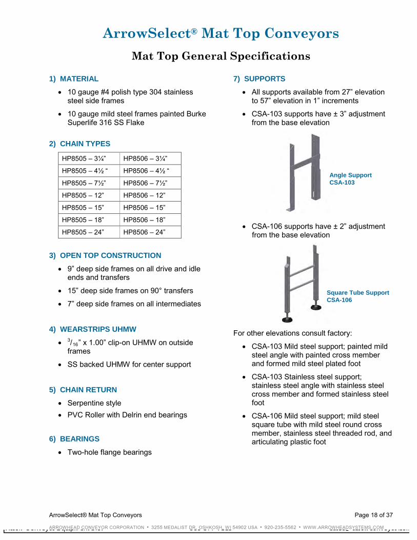
• Two-hole flange bearings 7) SUPPORTS
• All supports available from 27” elevation to 57” elevation in 1” increments
• CSA-103 supports have ± 3” adjustment from the base elevation
• CSA-106 supports have ± 2” adjustment from the base elevation
Angle Support CSA-103
Square Tube Support CSA-106
Becca
Rectangle
ArrowSelect® Table Top Conveyors Page 6 of 37
ARROWHEAD CONVEYOR CORPORATION • 3255 MEDALIST DR. OSHKOSH, WI 54902 USA • 920-235-5562 • WWW.ARROWHEADSYSTEMS.COM
- continued
For other elevations consult factory:
• CSA-103 Mild steel support; painted mild steel angle with painted cross member and formed mild steel plated foot
• CSA-103 Stainless steel support; stainless steel angle with stainless steel cross member and formed stainless steel foot
• CSA-106 Mild steel support; mild steel square tube with mild steel round cross member, stainless steel threaded rod, and articulating plastic foot
• CSA-106 Stainless steel support; stainless steel square tube with stainless steel round cross member, stainless steel threaded rod, and articulating plastic foot
8) GUIDE RAIL BRACKETS
• Adjustable only; stainless steel or mild steel plated, formed ¼” x 1½” material slotted for vertical and horizontal adjustment
9) GUIDE RAILS
• Consist of formed value guide stainless steel with UHMW round (VGSSR), flat (VGSSF), and T-shaped (VGSST) insert and stainless steel compression clips.
10) MOTOR MOUNT
• Vertically flange mounted drive motor is standard; under slung and under slung mounts are optional at an additional cost.
• Left hand motor mount is standard; right hand optional
11) DRIVE PACKAGE FOR STANDARD FLANGE MOUNTED DRIVE
• Inverter duty drive is standard “C” face motor (230 / 460-3-60) with right angle reducer
• Motor horsepower available:
½ ¾ 1 1½
• Nominal Speeds available (in feet per minute) at 60 hertz:
53 66 89
106 133 177 266
• Other intermediate speeds can be acquired by incorporating variable frequency drives NOTE: For additional speeds, consult the manufacturer. Longer deliveries may be required.
12) DRIVE PACKAGE FOR OPTIONAL UNDER SLUNG MOUNTED DRIVE
• Inverter duty drive is standard “C” face motor (230 / 460-3-60) with right angle reducer
• Motor horsepower available:
½ ¾ 1 1½
• Speeds available (in feet per minute) at 60 hertz:
25 30 40 50
60 70 80 90
100 120 140 150
180 200
• Other intermediate speeds can be acquired by incorporating variable frequency drives
NOTE: For additional speeds, consult the manufacturer. Longer deliveries may be required.
ArrowSelect® Table Top Conveyors Page 7 of 37
ARROWHEAD CONVEYOR CORPORATION • 3255 MEDALIST DR. OSHKOSH, WI 54902 USA • 920-235-5562 • WWW.ARROWHEADSYSTEMS.COM
Table Top Engineering / Application
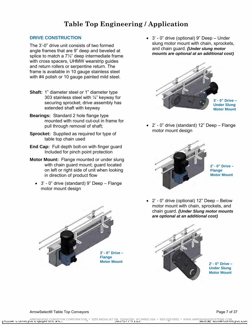
DRIVE CONSTRUCTION The 3’-0” drive unit consists of two formed angle frames that are 9” deep and beveled at splice to match a 7½” deep intermediate frame with cross spacers, UHMW wearstrip guides and return rollers or serpentine return. The frame is available in 10 gauge stainless steel with #4 polish or 10 gauge painted mild steel. Shaft: 1” diameter steel or 1” diameter type
303 stainless steel with ¼” keyway for securing sprocket; drive assembly has extended shaft with keyway
Bearings: Standard 2 hole flange type mounted with round cut-out in frame for pull through removal of shaft;
Sprocket: Supplied as required for type of table top chain used
End Cap: Full depth bolt-on with finger guard Included for pinch point protection
Motor Mount: Flange mounted or under slung with chain guard mount; guard located on left or right side of unit when looking in direction of product flow
• 3’ - 0” drive (standard) 9” Deep – Flange motor mount design
• 3’ - 0” drive (optional) 9” Deep – Under slung motor mount with chain, sprockets, and chain guard. (Under slung motor mounts are optional at an additional cost)
• 2’ - 0” drive (standard) 12” Deep – Flange motor mount design
• 2’ - 0” drive (optional) 12” Deep – Below motor mount with chain, sprockets, and chain guard. (Under Slung motor mounts are optional at an additional cost)
3’ - 0” Drive – Flange Motor Mount
3’ - 0” Drive – Under Slung Motor Mount
2’ - 0” Drive – Flange Motor Mount
2’ - 0” Drive – Under Slung Motor Mount
ArrowSelect® Table Top Conveyors Page 8 of 37
ARROWHEAD CONVEYOR CORPORATION • 3255 MEDALIST DR. OSHKOSH, WI 54902 USA • 920-235-5562 • WWW.ARROWHEADSYSTEMS.COM
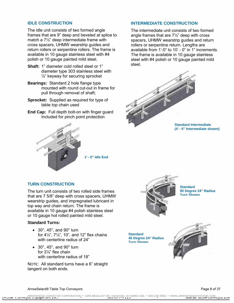
IDLE CONSTRUCTION The idle unit consists of two formed angle frames that are 9” deep and beveled at splice to match a 7½” deep intermediate frame with cross spacers, UHMW wearstrip guides and return rollers or serpentine rollers. The frame is available in 10 gauge stainless steel with #4 polish or 10 gauge painted mild steel. Shaft: 1” diameter cold rolled steel or 1”
diameter type 303 stainless steel with ¼” keyway for securing sprocket
Bearings: Standard 2 hole flange type mounted with round cut-out in frame for pull through removal of shaft;
Sprocket: Supplied as required for type of table top chain used
End Cap: Full depth bolt-on with finger guard Included for pinch point protection
TURN CONSTRUCTION The turn unit consists of two rolled side frames that are 7 5/8” deep with cross spacers, UHMW wearstrip guides, and impregnated lubricant in top way and chain return. The frame is available in 10 gauge #4 polish stainless steel or 10 gauge hot rolled painted mild steel. Standard Turns:
• 30°, 45°, and 90° turn for 4½”, 7½”, 10”, and 12” flex chains with centerline radius of 24”
• 30°, 45°, and 90° turn for 3¼” flex chain with centerline radius of 18”
NOTE: All standard turns have a 6” straight tangent on both ends.
INTERMEDIATE CONSTRUCTION
The intermediate unit consists of two formed angle frames that are 7½” deep with cross spacers, UHMW wearstrip guides and return rollers or serpentine return. Lengths are available from 1’-0” to 10’ - 0” in 1” increments. The frame is available in 10 gauge stainless steel with #4 polish or 10 gauge painted mild steel.
1’ - 0” Idle End
Standard 90 Degree 24” Radius Turn Shown
Standard Intermediate (4’ - 0” Intermediate shown)
Standard 45 Degree 24” Radius Turn Shown
ArrowSelect® Table Top Conveyors Page 9 of 37
ARROWHEAD CONVEYOR CORPORATION • 3255 MEDALIST DR. OSHKOSH, WI 54902 USA • 920-235-5562 • WWW.ARROWHEADSYSTEMS.COM
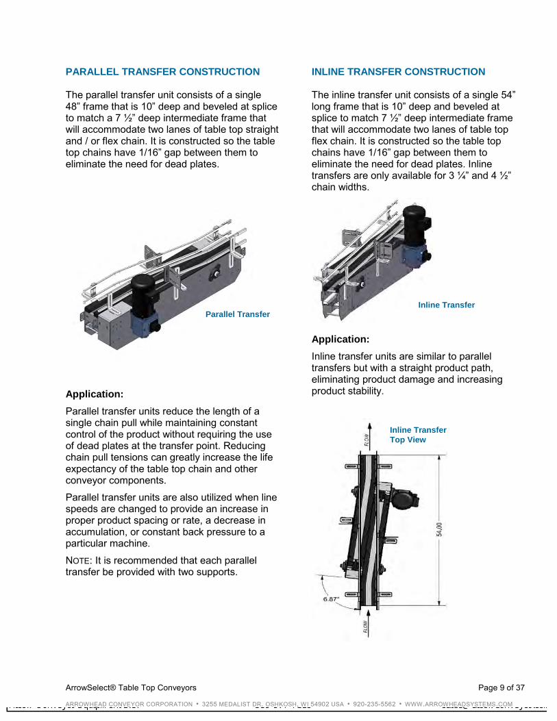
PARALLEL TRANSFER CONSTRUCTION The parallel transfer unit consists of a single 48” frame that is 10” deep and beveled at splice to match a 7 ½” deep intermediate frame that will accommodate two lanes of table top straight and / or flex chain. It is constructed so the table top chains have 1/16” gap between them to eliminate the need for dead plates.
Application: Parallel transfer units reduce the length of a single chain pull while maintaining constant control of the product without requiring the use of dead plates at the transfer point. Reducing chain pull tensions can greatly increase the life expectancy of the table top chain and other conveyor components. Parallel transfer units are also utilized when line speeds are changed to provide an increase in proper product spacing or rate, a decrease in accumulation, or constant back pressure to a particular machine. NOTE: It is recommended that each parallel transfer be provided with two supports.
INLINE TRANSFER CONSTRUCTION The inline transfer unit consists of a single 54” long frame that is 10” deep and beveled at splice to match 7 ½” deep intermediate frame that will accommodate two lanes of table top flex chain. It is constructed so the table top chains have 1/16” gap between them to eliminate the need for dead plates. Inline transfers are only available for 3 ¼” and 4 ½” chain widths.
Application: Inline transfer units are similar to parallel transfers but with a straight product path, eliminating product damage and increasing product stability.
Parallel Transfer Inline Transfer
Inline Transfer Top View

ArrowSelect® Table Top Conveyors Page 10 of 37
ARROWHEAD CONVEYOR CORPORATION • 3255 MEDALIST DR. OSHKOSH, WI 54902 USA • 920-235-5562 • WWW.ARROWHEADSYSTEMS.COM
ADJUSTABLE COPE CONSTRUCTION The adjustable cope unit consists of two angle frames that are 7 ½” deep with cross spacers, UHMW wearstrip guides and return roller. The modular design allows for angle adjustment ± 10°.
Application: Adjustable copes are utilized where elevation changes are required. Several aspects must be considered when utilizing copes, including but not limited to the following:
• Product slippage
• Tipping of the product
• Minimum back flex radius of the conveyor chain
• Possible tab chain requirement
• Maximum ¾” per foot inclines and declines allowable (consult factory for anything greater)
TRANSFER PLATE CONSTRUCTION The roller transfer plate unit consists of solid marbett plates with stainless steel axles and LBP rollers.
The stainless steel end transfer plate unit consists of a full width plate with bevel on chain side.
The stainless steel side transfer plate unit consists of a vertically adjustable stainless steel plate.
Application: Transfer plates are utilized to bridge the gap between conveyor sprockets on end to end transfers. Transfer plates are often NOT self clearing. Where minimal gaps are required, parallel or inline transfers are recommended.
LBP Roller Transfer Plate
Stainless Steel End Transfer Plate
Stainless Steel ½” Side Transfer Plate
Adjustable Cope Section Turn Interface
ArrowSelect® Table Top Conveyors Page 11 of 37
ARROWHEAD CONVEYOR CORPORATION • 3255 MEDALIST DR. OSHKOSH, WI 54902 USA • 920-235-5562 • WWW.ARROWHEADSYSTEMS.COM
Table Top General Information
TABLE TOP CHAIN SELECTION When selecting the proper table top chain, it is important to consider the following factors: Product: Determine the type of product the conveyor will transport. What type of material is the product? What type of material is the container? Will the container be filled with chemicals that have corrosive properties? Environmental Conditions: Determine the temperatures and atmospheric conditions in which the conveyor will operate. Will the atmosphere be abrasive, combustible, or explosive? Will there be corrosive material? Accumulation or Transportation: Determine whether the product will be accumulated or simply transported. Conveyor Wash down: Determine the chemical properties of wash down solutions required for your conveyor. Will the wash down solutions be compatible with your chain selection? Chain Lubrication: Determine the type of lubrication necessary to maintain the type of chain. The type of lubrication can greatly enhance the wearstrip to chain compatibility. What type of material is the chain? Lubrication is required for steel and stainless steel chains and recommended for all chains. Proper lubrication will provide the lowest friction factor between the product, chain, and chain wearstrip.
CHAIN AND PRODUCT COMPATIBILITY GUIDE Use the following guidelines when considering the compatibility of the chain and product: Stainless Steel Chains:
• Soft drink and brewery glass handling conveyor
• Glass handling conveyor where glass breakage is present
• Food processing and industrial where some acids or chemicals may be handled
Steel Chains:
• Glass manufacturing plants
• Industrial applications Plastic Chains:
• Soft drink and brewery steel and aluminum can handling conveyor
• Paper container handling
• Plastic container handling
ArrowSelect® Table Top Conveyors Page 12 of 37
ARROWHEAD CONVEYOR CORPORATION • 3255 MEDALIST DR. OSHKOSH, WI 54902 USA • 920-235-5562 • WWW.ARROWHEADSYSTEMS.COM
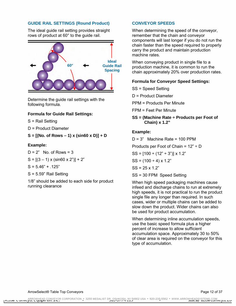
GUIDE RAIL SETTINGS (Round Product) The ideal guide rail setting provides straight rows of product at 60° to the guide rail.
Determine the guide rail settings with the following formula.
Formula for Guide Rail Settings: S = Rail Setting D = Product Diameter S = [(No. of Rows – 1) x (sin60 x D)] + D
Example: D = 2” No. of Rows = 3 S = [(3 – 1) x (sin60 x 2”)] + 2” S = 5.46” + .125” S = 5.59” Rail Setting 1/8” should be added to each side for product running clearance
CONVEYOR SPEEDS When determining the speed of the conveyor, remember that the chain and conveyor components will last longer if you do not run the chain faster than the speed required to properly carry the product and maintain production machine rates. When conveying product in single file to a production machine, it is common to run the chain approximately 20% over production rates.
Formula for Conveyor Speed Settings: SS = Speed Setting D = Product Diameter PPM = Products Per Minute FPM = Feet Per Minute SS = (Machine Rate ÷ Products per Foot of
Chain) x 1.2”
Example: D = 3” Machine Rate = 100 PPM Products per Foot of Chain = 12” ÷ D SS = [100 ÷ (12” ÷ 3”)] x 1.2” SS = (100 ÷ 4) x 1.2” SS = 25 x 1.2” SS = 30 FPM Speed Setting When high speed packaging machines cause infeed and discharge chains to run at extremely high speeds, it is not practical to run the product single file any longer than required. In such cases, wider or multiple chains can be added to slow down the product. Wider chains can also be used for product accumulation. When determining inline accumulation speeds, use the basic speed formula plus a higher percent of increase to allow sufficient accumulation space. Approximately 30 to 50% of clear area is required on the conveyor for this type of accumulation.
60° Ideal
Guide Rail Spacing
ArrowSelect® Table Top Conveyors Page 13 of 37
ARROWHEAD CONVEYOR CORPORATION • 3255 MEDALIST DR. OSHKOSH, WI 54902 USA • 920-235-5562 • WWW.ARROWHEADSYSTEMS.COM
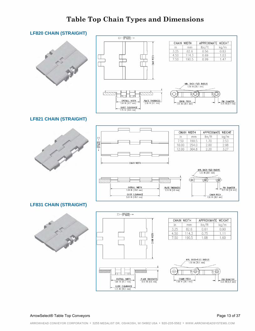
Table Top Chain Types and Dimensions
LF820 CHAIN (STRAIGHT) LF821 CHAIN (STRAIGHT) LF831 CHAIN (STRAIGHT)
ArrowSelect® Table Top Conveyors Page 14 of 37
ARROWHEAD CONVEYOR CORPORATION • 3255 MEDALIST DR. OSHKOSH, WI 54902 USA • 920-235-5562 • WWW.ARROWHEADSYSTEMS.COM
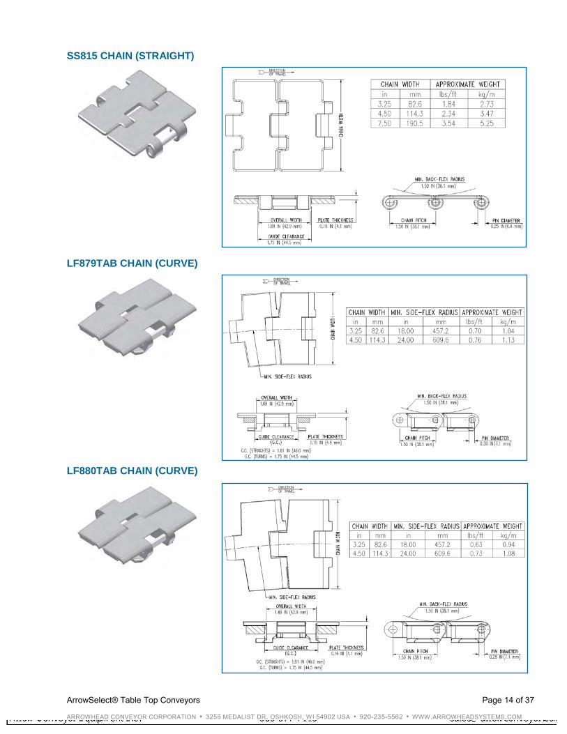
SS815 CHAIN (STRAIGHT) LF879TAB CHAIN (CURVE) LF880TAB CHAIN (CURVE)
ArrowSelect® Table Top Conveyors Page 15 of 37
ARROWHEAD CONVEYOR CORPORATION • 3255 MEDALIST DR. OSHKOSH, WI 54902 USA • 920-235-5562 • WWW.ARROWHEADSYSTEMS.COM
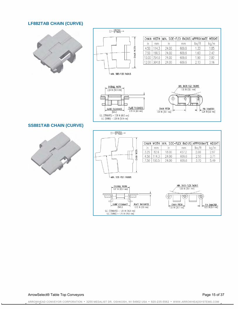
LF882TAB CHAIN (CURVE) SS881TAB CHAIN (CURVE)
ArrowSelect® Table Top Conveyors Page 16 of 37
ARROWHEAD CONVEYOR CORPORATION • 3255 MEDALIST DR. OSHKOSH, WI 54902 USA • 920-235-5562 • WWW.ARROWHEADSYSTEMS.COM
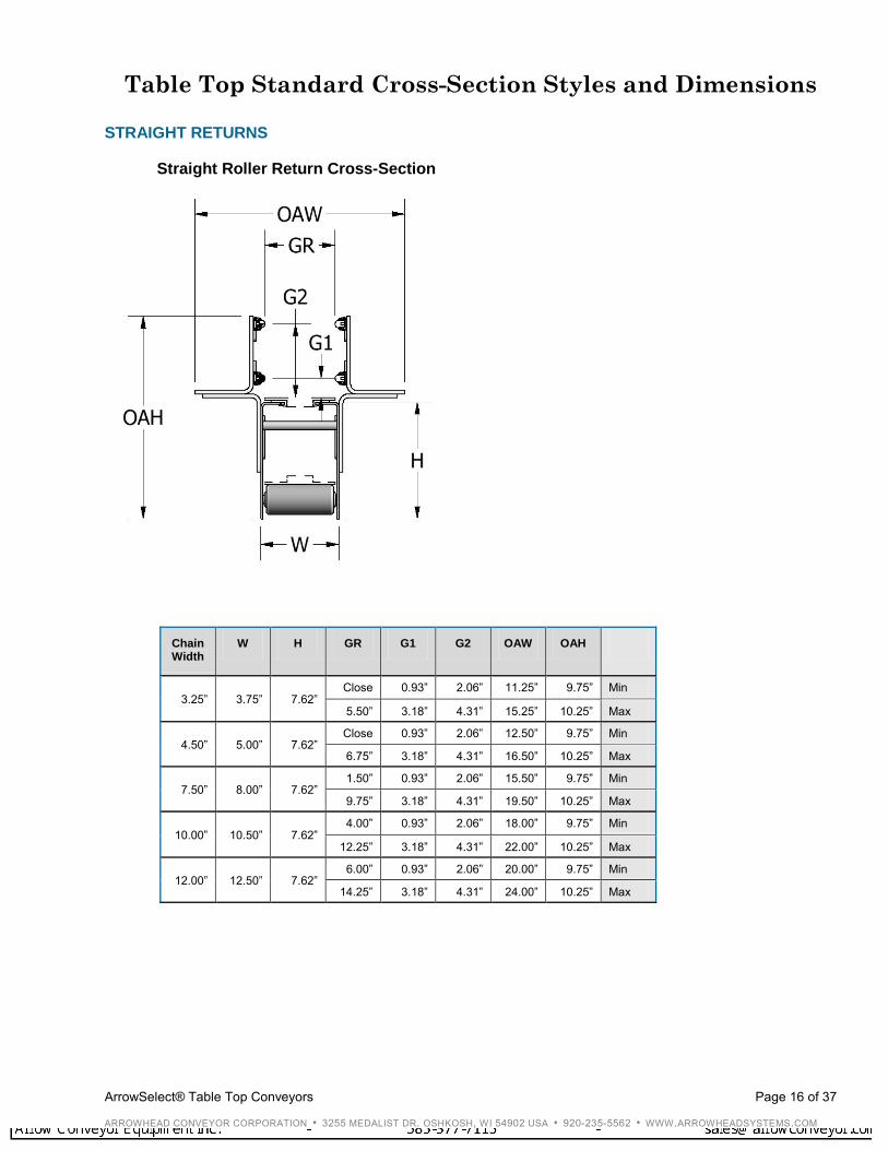
Table Top Standard Cross-Section Styles and Dimensions
STRAIGHT RETURNS
Straight Roller Return Cross-Section
Chain Width
W H GR G1 G2 OAW OAH
3.25” 3.75” 7.62” Close 0.93” 2.06” 11.25” 9.75” Min
5.50” 3.18” 4.31” 15.25” 10.25” Max
4.50” 5.00” 7.62” Close 0.93” 2.06” 12.50” 9.75” Min
6.75” 3.18” 4.31” 16.50” 10.25” Max
7.50” 8.00” 7.62” 1.50” 0.93” 2.06” 15.50” 9.75” Min
9.75” 3.18” 4.31” 19.50” 10.25” Max
10.00” 10.50” 7.62” 4.00” 0.93” 2.06” 18.00” 9.75” Min
12.25” 3.18” 4.31” 22.00” 10.25” Max
12.00” 12.50” 7.62” 6.00” 0.93” 2.06” 20.00” 9.75” Min
14.25” 3.18” 4.31” 24.00” 10.25” Max
ArrowSelect® Table Top Conveyors Page 17 of 37
ARROWHEAD CONVEYOR CORPORATION • 3255 MEDALIST DR. OSHKOSH, WI 54902 USA • 920-235-5562 • WWW.ARROWHEADSYSTEMS.COM
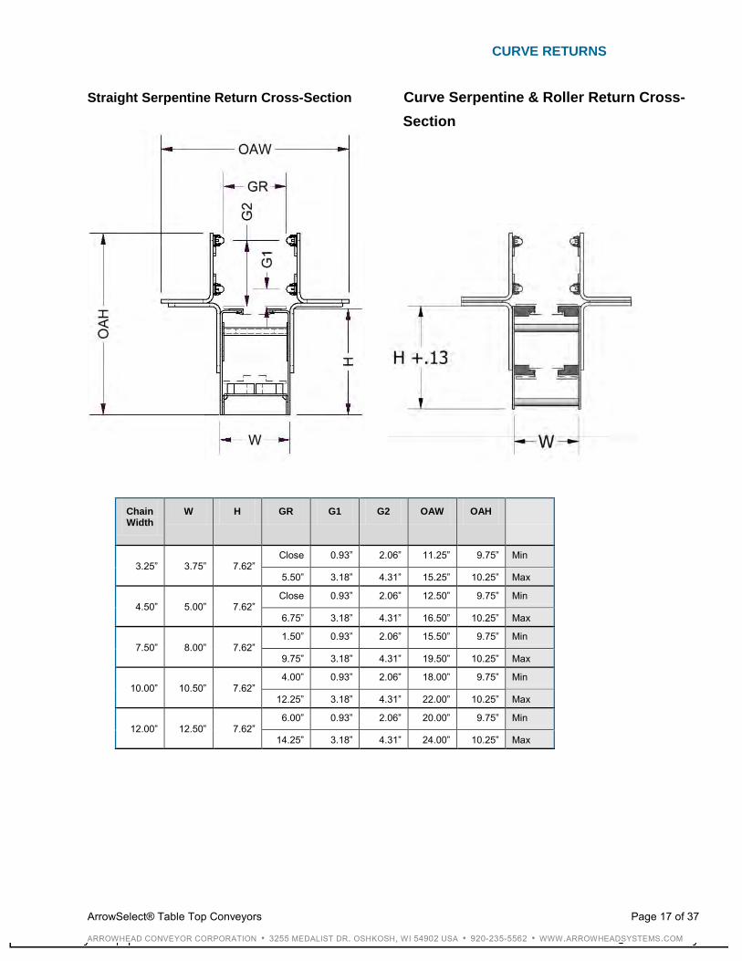
CURVE RETURNS
Straight Serpentine Return Cross-Section Curve Serpentine & Roller Return Cross- Section
Chain Width
W H GR G1 G2 OAW OAH
3.25” 3.75” 7.62” Close 0.93” 2.06” 11.25” 9.75” Min
5.50” 3.18” 4.31” 15.25” 10.25” Max
4.50” 5.00” 7.62” Close 0.93” 2.06” 12.50” 9.75” Min
6.75” 3.18” 4.31” 16.50” 10.25” Max
7.50” 8.00” 7.62” 1.50” 0.93” 2.06” 15.50” 9.75” Min
9.75” 3.18” 4.31” 19.50” 10.25” Max
10.00” 10.50” 7.62” 4.00” 0.93” 2.06” 18.00” 9.75” Min
12.25” 3.18” 4.31” 22.00” 10.25” Max
12.00” 12.50” 7.62” 6.00” 0.93” 2.06” 20.00” 9.75” Min
14.25” 3.18” 4.31” 24.00” 10.25” Max
ArrowSelect® Mat Top Conveyors Page 18 of 37
ARROWHEAD CONVEYOR CORPORATION • 3255 MEDALIST DR. OSHKOSH, WI 54902 USA • 920-235-5562 • WWW.ARROWHEADSYSTEMS.COM
ArrowSelect® Mat Top Conveyors Mat Top General Specifications
1) MATERIAL
• 10 gauge #4 polish type 304 stainless steel side frames
• 10 gauge mild steel frames painted Burke Superlife 316 SS Flake
2) CHAIN TYPES
HP8505 – 3¼” HP8506 – 3¼”
HP8505 – 4½ “ HP8506 – 4½ “
HP8505 – 7½” HP8506 – 7½”
HP8505 – 12” HP8506 – 12”
HP8505 – 15” HP8506 – 15”
HP8505 – 18” HP8506 – 18”
HP8505 – 24” HP8506 – 24” 3) OPEN TOP CONSTRUCTION
• 9” deep side frames on all drive and idle ends and transfers
• 15” deep side frames on 90° transfers
• 7” deep side frames on all intermediates 4) WEARSTRIPS UHMW
• 3/16” x 1.00” clip-on UHMW on outside frames
• SS backed UHMW for center support 5) CHAIN RETURN
• Serpentine style • PVC Roller with Delrin end bearings
6) BEARINGS
• Two-hole flange bearings
7) SUPPORTS
• All supports available from 27” elevation to 57” elevation in 1” increments
• CSA-103 supports have ± 3” adjustment from the base elevation
• CSA-106 supports have ± 2” adjustment from the base elevation
For other elevations consult factory:
• CSA-103 Mild steel support; painted mild steel angle with painted cross member and formed mild steel plated foot
• CSA-103 Stainless steel support; stainless steel angle with stainless steel cross member and formed stainless steel foot
• CSA-106 Mild steel support; mild steel square tube with mild steel round cross member, stainless steel threaded rod, and articulating plastic foot
Angle Support CSA-103
Square Tube Support CSA-106

ArrowSelect® Mat Top Conveyors Page 19 of 37
ARROWHEAD CONVEYOR CORPORATION • 3255 MEDALIST DR. OSHKOSH, WI 54902 USA • 920-235-5562 • WWW.ARROWHEADSYSTEMS.COM
- continued
• CSA-106 Stainless steel support; stainless steel square tube with stainless steel round cross member, stainless steel threaded rod, and articulating plastic foot
8) GUIDE RAIL BRACKETS
• Adjustable only; stainless steel or mild steel plated, formed ¼” x 1½” material slotted for vertical and horizontal adjustment
9) GUIDE RAILS
• Formed stainless steel with UHMW round or 1¼” flat profile insert and stainless steel compression clips; double high
10) MOTOR MOUNT
• All drive motors to be flange mounted left hand or right hand assemblies as required
11) DRIVE PACKAGE
• Inverter duty drives as standard “C” face motors (230 / 460-3-60) with right angle reducers
• Motor horsepower available:
1 1½ 2
• Speeds available (in feet per minute) at 60 hertz:
44 53 66 89
106 133 177 266
• Other intermediate speeds can be acquired by incorporating variable frequency drives NOTE: For additional speeds, consult the manufacturer. Longer deliveries may be required.
ArrowSelect® Mat Top Conveyors Page 20 of 37
ARROWHEAD CONVEYOR CORPORATION • 3255 MEDALIST DR. OSHKOSH, WI 54902 USA • 920-235-5562 • WWW.ARROWHEADSYSTEMS.COM
Mat Top Engineering / Application
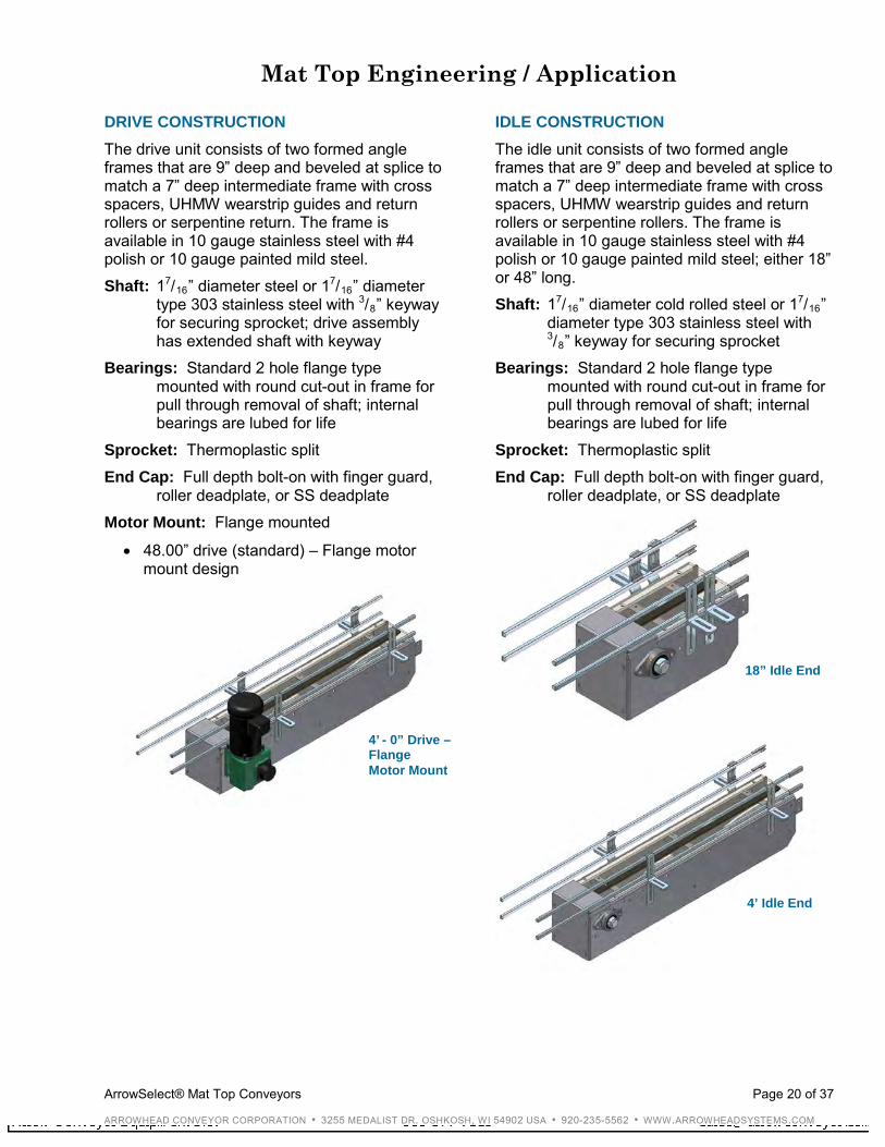
DRIVE CONSTRUCTION The drive unit consists of two formed angle frames that are 9” deep and beveled at splice to match a 7” deep intermediate frame with cross spacers, UHMW wearstrip guides and return rollers or serpentine return. The frame is available in 10 gauge stainless steel with #4 polish or 10 gauge painted mild steel. Shaft: 17/16” diameter steel or 17/16” diameter
type 303 stainless steel with 3/8” keyway for securing sprocket; drive assembly has extended shaft with keyway
Bearings: Standard 2 hole flange type mounted with round cut-out in frame for pull through removal of shaft; internal bearings are lubed for life
Sprocket: Thermoplastic split End Cap: Full depth bolt-on with finger guard,
roller deadplate, or SS deadplate Motor Mount: Flange mounted
• 48.00” drive (standard) – Flange motor mount design
IDLE CONSTRUCTION The idle unit consists of two formed angle frames that are 9” deep and beveled at splice to match a 7” deep intermediate frame with cross spacers, UHMW wearstrip guides and return rollers or serpentine rollers. The frame is available in 10 gauge stainless steel with #4 polish or 10 gauge painted mild steel; either 18” or 48” long. Shaft: 17/16” diameter cold rolled steel or 17/16”
diameter type 303 stainless steel with 3/8” keyway for securing sprocket
Bearings: Standard 2 hole flange type mounted with round cut-out in frame for pull through removal of shaft; internal bearings are lubed for life
Sprocket: Thermoplastic split End Cap: Full depth bolt-on with finger guard,
roller deadplate, or SS deadplate
4’ - 0” Drive – Flange Motor Mount
4’ Idle End
18” Idle End

ArrowSelect® Mat Top Conveyors Page 21 of 37
ARROWHEAD CONVEYOR CORPORATION • 3255 MEDALIST DR. OSHKOSH, WI 54902 USA • 920-235-5562 • WWW.ARROWHEADSYSTEMS.COM
INTERMEDIATE CONSTRUCTION The intermediate unit consists of two formed angle frames that are 7” deep with cross spacers, UHMW wearstrip guides and return rollers or serpentine return. Lengths are available from 6” to 5’ - 0” in 1” increments and from 5’ - 6” to 10’ - 0” in 6” increments. The frame is available in 10 gauge stainless steel with #4 polish or 10 gauge painted mild steel.
Application: Intermediate sections are used for simple transportation and accumulation between drive and idle sections.
90° TRANSFER CONSTRUCTION The 90° transfer unit consists of four side frames that are 15” deep with cross spacers, and UHMW wearstrip guides. The frame is available in 10 gauge #4 polish stainless steel or 10 gauge painted mild steel.
Application: 90° transfers are used for direction and / or speed changes. They are available in standard and reverse flow configurations.
Standard 90° Transfers:
Infeed Discharge 15” - 15”
15” - 18”
18” - 18”
18” - 24”
24” - 24”
Standard Intermediate
90° Transfer

ArrowSelect® Mat Top Conveyors Page 22 of 37
ARROWHEAD CONVEYOR CORPORATION • 3255 MEDALIST DR. OSHKOSH, WI 54902 USA • 920-235-5562 • WWW.ARROWHEADSYSTEMS.COM
ADJUSTABLE COPE CONSTRUCTION The adjustable cope unit consists of two frames that are 7” deep with cross spacers, UHMW wearstrip guides and return roller. The modular design allows for angle adjustment ± 10°.
Application: Adjustable copes are utilized where elevation changes are required. Several aspects must be considered when utilizing copes, including but not limited to the following:
• Product slippage
• Tipping of the product
• Maximum ¾” per foot inclines and declines allowable (consult factory for anything greater)
TRANSFER PLATE CONSTRUCTION The roller transfer plate unit consists of stainless steel axles and LBP rollers.
The stainless steel end transfer plate unit consists of a full width plate with bevel on chain side.
The stainless steel side transfer plate unit consists of a side plate that adjusts vertically.
Application: Transfer plates are utilized to bridge the gap between conveyor sprockets on end to end transfers. Transfer plates are often NOT self clearing. Where minimal gaps are required, parallel transfers are recommended.
Adjustable Cope Section
LBP Roller Transfer Plate
Stainless Steel End Transfer Plate
Stainless Steel Side Transfer Plate

ArrowSelect® Mat Top Conveyors Page 23 of 37
ARROWHEAD CONVEYOR CORPORATION • 3255 MEDALIST DR. OSHKOSH, WI 54902 USA • 920-235-5562 • WWW.ARROWHEADSYSTEMS.COM
PARALLEL TRANSFER CONSTRUCTION The parallel transfer unit consists of a single 48” or 72” frame that is 9” deep and beveled at splice to match a 7” deep intermediate frame that will accommodate two lanes of chain. It is constructed so the chains are side by side to eliminate the need for a dead plate.
Application: Parallel transfer units reduce the length of a single chain pull while maintaining constant control of the product without requiring the use of dead plates at the transfer point. Reducing chain pull tensions can greatly increase the life expectancy of the mat top chain and other conveyor components. Parallel transfer units are also utilized when line speeds are changed to provide an increase in proper product spacing or rate, a decrease in accumulation, or constant back pressure to a particular machine. NOTE: It is recommended that each parallel transfer be provided with two supports.
Standard Parallel Transfers:
Infeed Discharge 3.25” - 3.25”
3.25” - 4.5”
3.25” - 7.5”
4.5” - 3.25”
4.5” - 4.5”
4.5” - 7.5”
4.5” - 12”
7.5” - 4.5”
7.5” - 7.5”
7.5” - 12”
7.5” - 15”
12” - 7.5”
12” - 12”
12” - 15”
12” - 18”
15” - 12”
15” - 15”
15” - 18”
15” - 24”
18” - 15”
18” - 18”
18” - 24”
24” - 18”
24” - 24”
Parallel Transfer

ArrowSelect® Mat Top Conveyors Page 24 of 37
ARROWHEAD CONVEYOR CORPORATION • 3255 MEDALIST DR. OSHKOSH, WI 54902 USA • 920-235-5562 • WWW.ARROWHEADSYSTEMS.COM
Mat Top General Information
MAT TOP CHAIN SELECTION When selecting the proper mat top chain, it is important to consider the following factors: Product: Determine the type of product the conveyor will transport. What type of material is the product? What type of material is the container? Will the container be filled with chemicals that have corrosive properties? Environmental Conditions: Determine the temperatures and atmospheric conditions in which the conveyor will operate. Will the atmosphere be abrasive, combustible, or explosive? Will there be corrosive material? Accumulation or Transportation: Determine whether the product will be accumulated or simply transported. Conveyor Washdown: Determine the chemical properties of washdown solutions required for your conveyor. Will the washdown solutions be compatible with your chain selection? Chain Lubrication: Determine the type of lubrication necessary to maintain the type of chain. The type of lubrication can greatly enhance the wearstrip to chain compatibility. What type of material is the chain? Lubrication is recommended for all chains. Proper lubrication will provide the lowest friction factor between the product, chain, and chain wearstrip.
CHAIN AND PRODUCT COMPATIBILITY GUIDE Use the following guidelines when considering the compatibility of the chain and product: Plastic Chains:
• Soft drink and brewery steel and aluminum can handling conveyor
• Paper container handling
• Plastic container handling

ArrowSelect® Mat Top Conveyors Page 25 of 37
ARROWHEAD CONVEYOR CORPORATION • 3255 MEDALIST DR. OSHKOSH, WI 54902 USA • 920-235-5562 • WWW.ARROWHEADSYSTEMS.COM
GUIDE RAIL SETTINGS (Round Product) The ideal guide rail setting provides straight rows of product at 60° to the guide rail.
Determine the guide rail settings with the following formula.
Formula for Guide Rail Settings: S = Rail Setting D = Product Diameter S = [(No. of Rows – 1) x (sin60 x D)] + D
Example: D = 2” No. of Rows = 3 S = [(3 – 1) x (sin60 x 2”)] + 2” S = 5.46” + .125” S = 5.59” Rail Setting 1/8” should be added to each side for product running clearance
CONVEYOR SPEEDS When determining the speed of the conveyor, remember that the chain and conveyor components will last longer if you do not run the chain faster than the speed required to properly carry the product and maintain production machine rates. When conveying product in single file to a production machine, it is common to run the chain approximately 20% over production rates.
Formula for Conveyor Speed Settings: SS = Speed Setting D = Product Diameter PPM = Products Per Minute FPM = Feet Per Minute SS = (Machine Rate ÷ Products per Foot of
Chain) x 1.2”
Example: D = 3” Machine Rate = 100 PPM Products per Foot of Chain = 12” ÷ D SS = [100 ÷ (12” ÷ 3”)] x 1.2” SS = (100 ÷ 4) x 1.2” SS = 25 x 1.2” SS = 30 FPM Speed Setting When high speed packaging machines cause infeed and discharge chains to run at extremely high speeds, it is not practical to run the product single file any longer than required. In such cases, wider chains can be added to slow down the product. Wider chains can also be used for product accumulation. When determining inline accumulation speeds, use the basic speed formula plus a higher percent of increase to allow sufficient accumulation space. Approximately 50% of clear area is required on the conveyor for this type of accumulation.
60° Ideal
Guide Rail Spacing
ArrowSelect® Mat Top Conveyors Page 26 of 37
ARROWHEAD CONVEYOR CORPORATION • 3255 MEDALIST DR. OSHKOSH, WI 54902 USA • 920-235-5562 • WWW.ARROWHEADSYSTEMS.COM
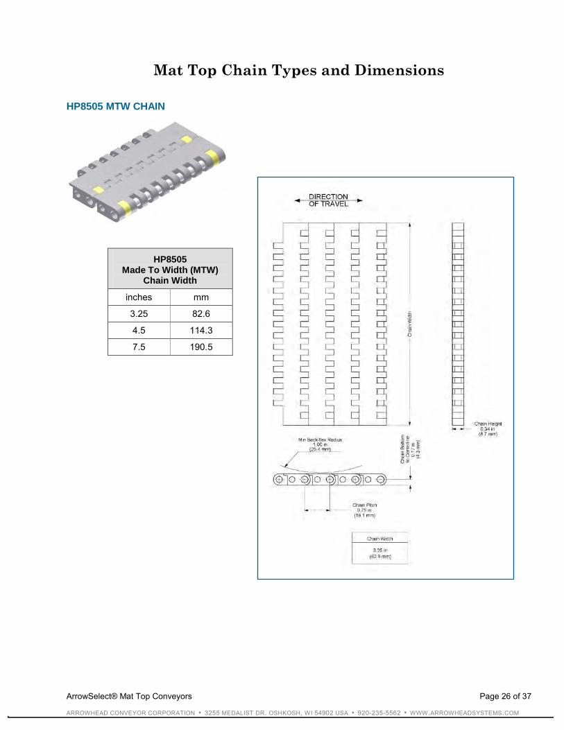
Mat Top Chain Types and Dimensions
HP8505 MTW CHAIN
HP8505 Made To Width (MTW)
Chain Width
inches mm
3.25 82.6
4.5 114.3
7.5 190.5
ArrowSelect® Mat Top Conveyors Page 27 of 37
ARROWHEAD CONVEYOR CORPORATION • 3255 MEDALIST DR. OSHKOSH, WI 54902 USA • 920-235-5562 • WWW.ARROWHEADSYSTEMS.COM
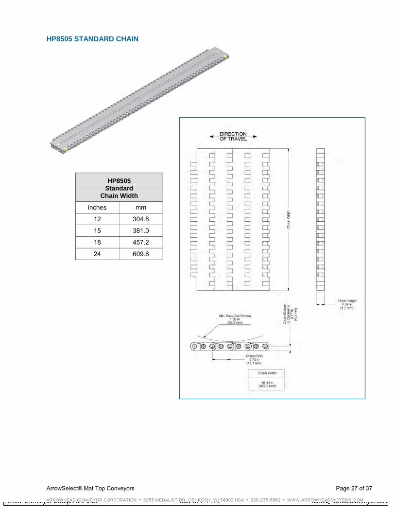
HP8505 STANDARD CHAIN
HP8505 Standard
Chain Width
inches mm
12 304.8
15 381.0
18 457.2
24 609.6

ArrowSelect® Mat Top Conveyors Page 28 of 37
ARROWHEAD CONVEYOR CORPORATION • 3255 MEDALIST DR. OSHKOSH, WI 54902 USA • 920-235-5562 • WWW.ARROWHEADSYSTEMS.COM
HP8506 MTW CHAIN
HP8506 Made To Width (MTW)
Chain Width
inches mm
3.25 82.6
4.5 114.3
7.5 190.5
ArrowSelect® Mat Top Conveyors Page 29 of 37
ARROWHEAD CONVEYOR CORPORATION • 3255 MEDALIST DR. OSHKOSH, WI 54902 USA • 920-235-5562 • WWW.ARROWHEADSYSTEMS.COM
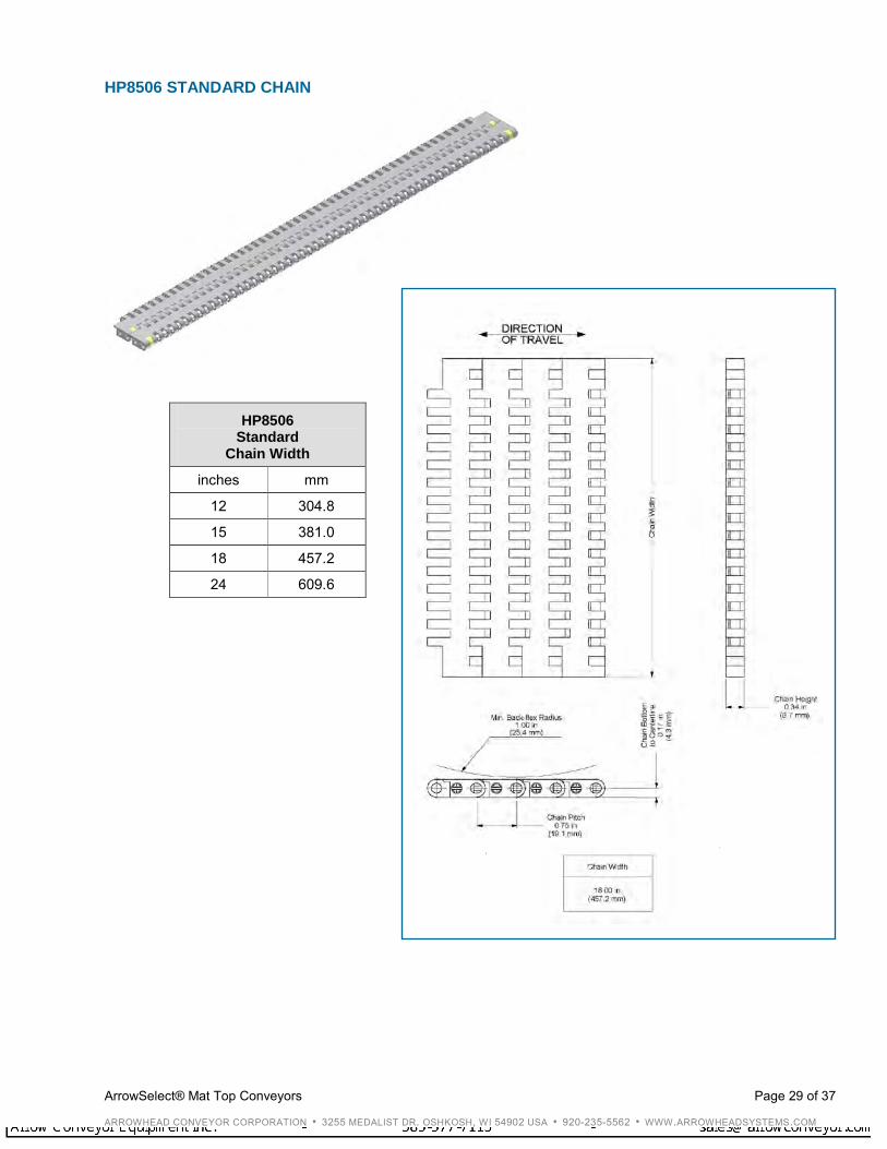
HP8506 STANDARD CHAIN
HP8506 Standard
Chain Width
inches mm
12 304.8
15 381.0
18 457.2
24 609.6

ArrowSelect® Mat Top Conveyors Page 30 of 37
ARROWHEAD CONVEYOR CORPORATION • 3255 MEDALIST DR. OSHKOSH, WI 54902 USA • 920-235-5562 • WWW.ARROWHEADSYSTEMS.COM
Mat Top Standard Cross-Section Styles and Dimensions
325 RETURNS
325 Roller Return Cross-Section
325 Serpentine Return Cross-Section
ArrowSelect® Mat Top Conveyors Page 31 of 37
ARROWHEAD CONVEYOR CORPORATION • 3255 MEDALIST DR. OSHKOSH, WI 54902 USA • 920-235-5562 • WWW.ARROWHEADSYSTEMS.COM
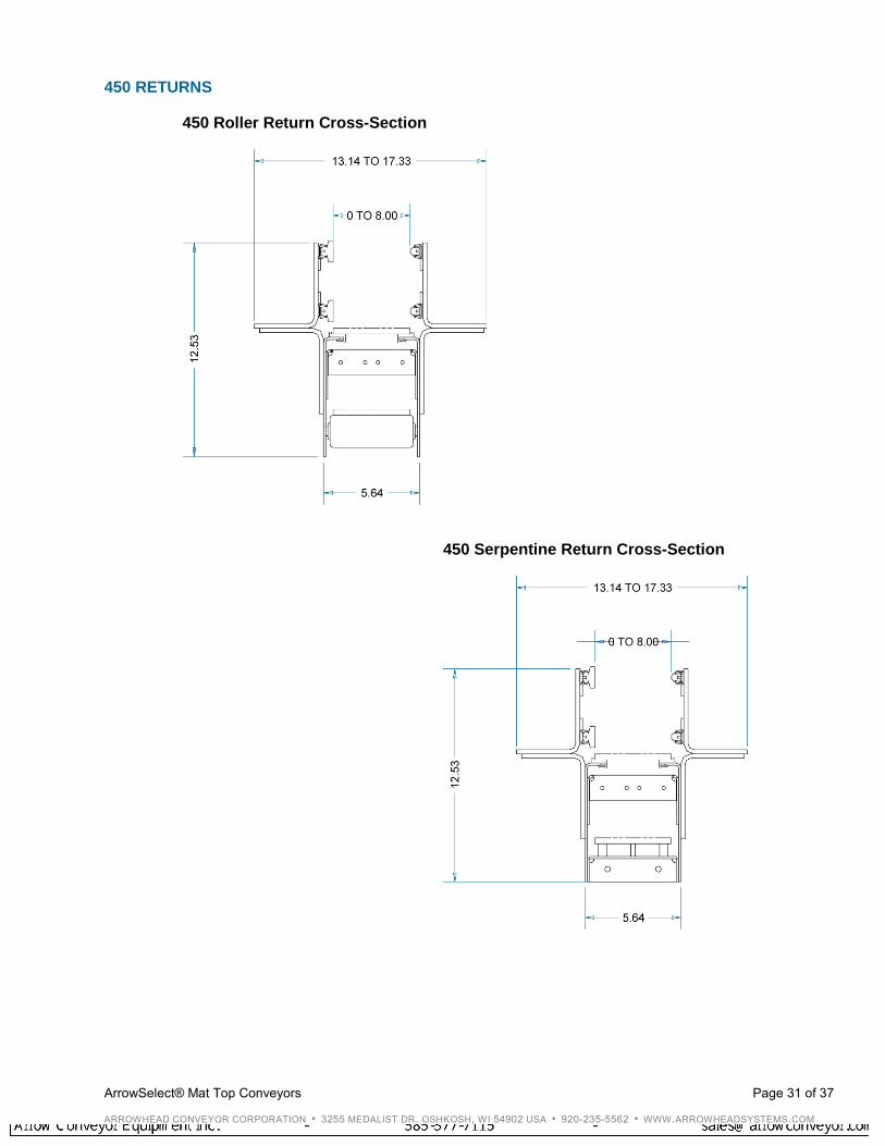
450 RETURNS
450 Roller Return Cross-Section
450 Serpentine Return Cross-Section
ArrowSelect® Mat Top Conveyors Page 32 of 37
ARROWHEAD CONVEYOR CORPORATION • 3255 MEDALIST DR. OSHKOSH, WI 54902 USA • 920-235-5562 • WWW.ARROWHEADSYSTEMS.COM
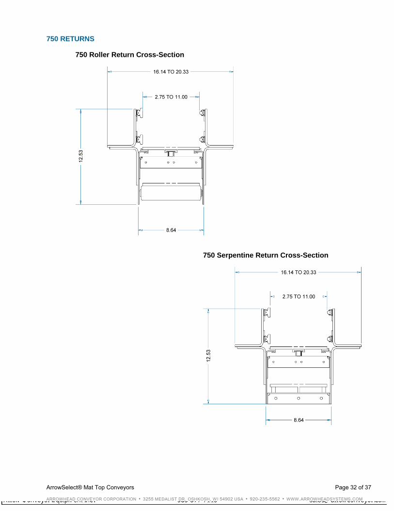
750 RETURNS
750 Roller Return Cross-Section
750 Serpentine Return Cross-Section

ArrowSelect® Mat Top Conveyors Page 33 of 37
ARROWHEAD CONVEYOR CORPORATION • 3255 MEDALIST DR. OSHKOSH, WI 54902 USA • 920-235-5562 • WWW.ARROWHEADSYSTEMS.COM
1200 RETURNS
1200 Roller Return Cross-Section
1200 Serpentine Return Cross-Section
ArrowSelect® Mat Top Conveyors Page 34 of 37
ARROWHEAD CONVEYOR CORPORATION • 3255 MEDALIST DR. OSHKOSH, WI 54902 USA • 920-235-5562 • WWW.ARROWHEADSYSTEMS.COM
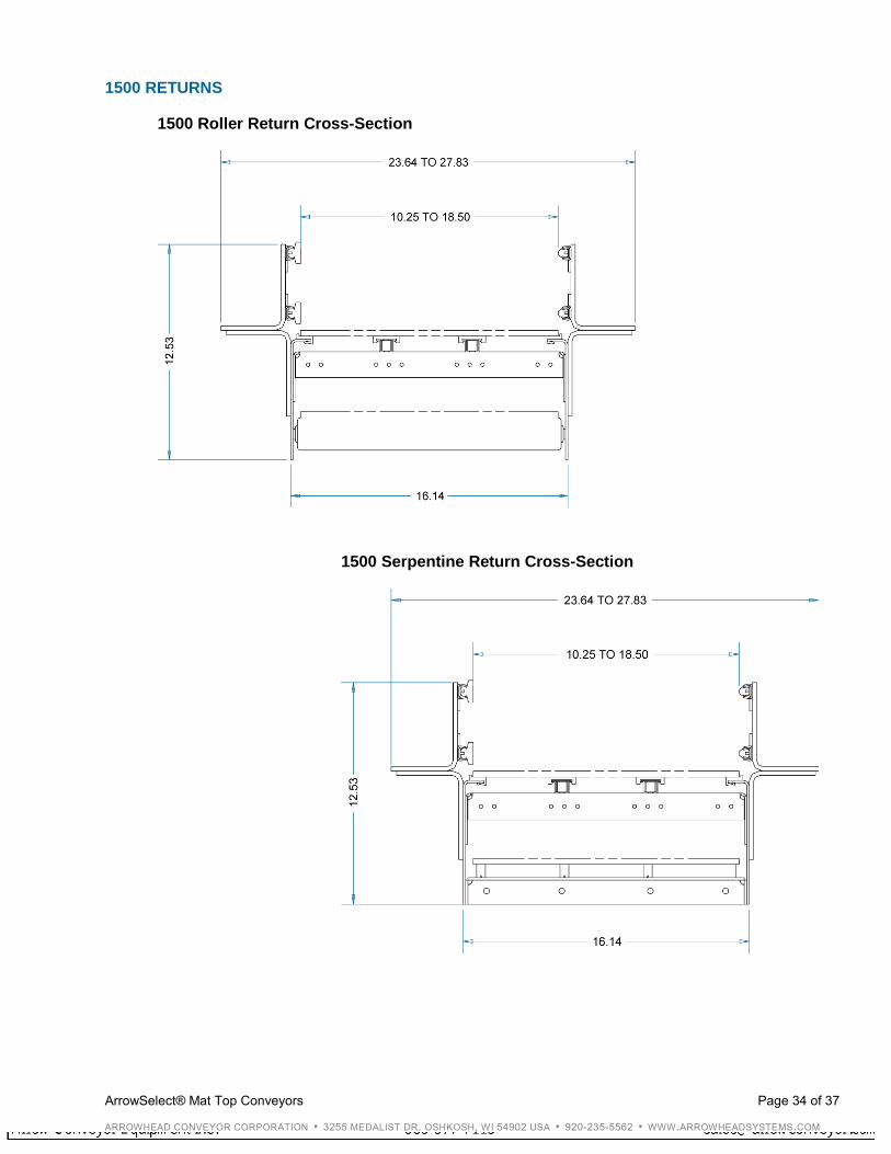
1500 RETURNS
1500 Roller Return Cross-Section
1500 Serpentine Return Cross-Section
ArrowSelect® Mat Top Conveyors Page 35 of 37
ARROWHEAD CONVEYOR CORPORATION • 3255 MEDALIST DR. OSHKOSH, WI 54902 USA • 920-235-5562 • WWW.ARROWHEADSYSTEMS.COM
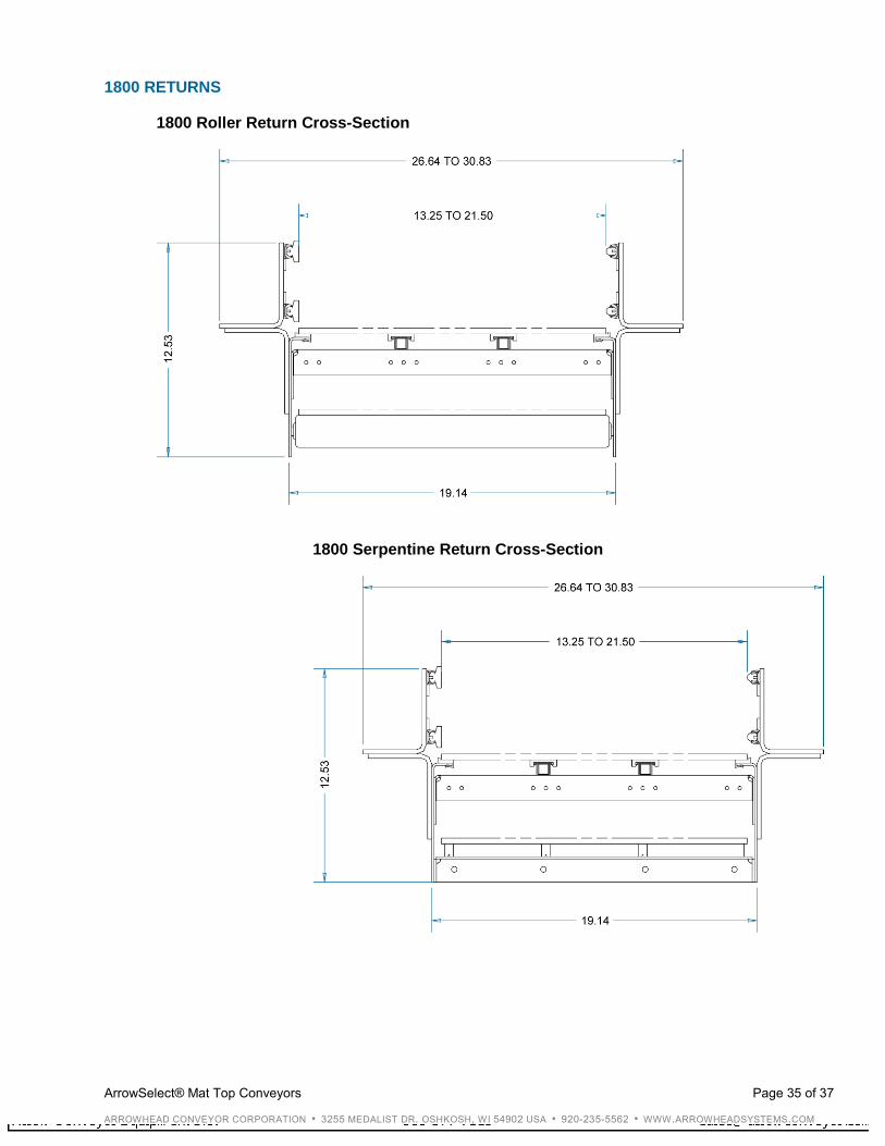
1800 RETURNS
1800 Roller Return Cross-Section
1800 Serpentine Return Cross-Section
ArrowSelect® Mat Top Conveyors Page 36 of 37
ARROWHEAD CONVEYOR CORPORATION • 3255 MEDALIST DR. OSHKOSH, WI 54902 USA • 920-235-5562 • WWW.ARROWHEADSYSTEMS.COM
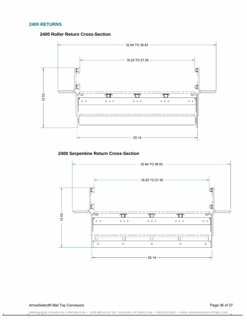
2400 RETURNS
2400 Roller Return Cross-Section
2400 Serpentine Return Cross-Section

ArrowSelect® Mat Top Conveyors Page 37 of 37
ARROWHEAD CONVEYOR CORPORATION • 3255 MEDALIST DR. OSHKOSH, WI 54902 USA • 920-235-5562 • WWW.ARROWHEADSYSTEMS.COM
Notes