
PWX SERIES - Mark Allen
12
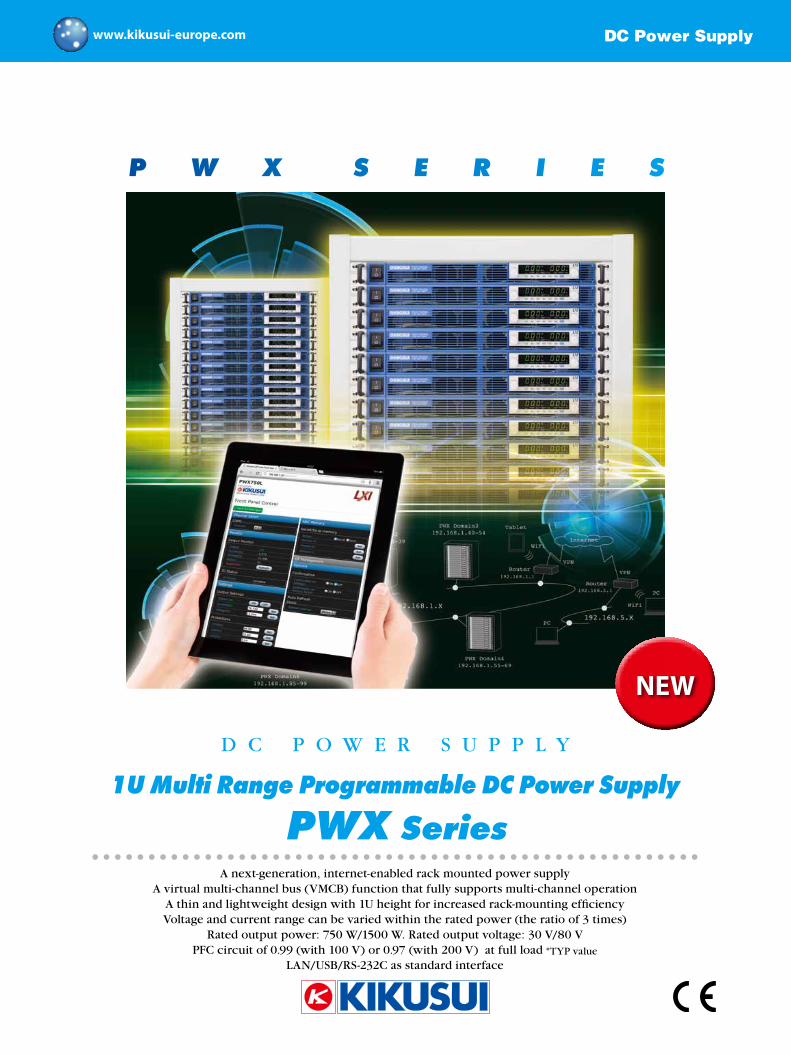
P W X S E R I E S NEW DC Power Supply www.kikusui-europe.com A next-generation, internet-enabled rack mounted power supply A virtual multi-channel bus (VMCB) function that fully supports multi-channel operation A thin and lightweight design with 1U height for increased rack-mounting efficiency Voltage and current range can be varied within the rated power (the ratio of 3 times) Rated output power: 750 W/1500 W. Rated output voltage: 30 V/80 V PFC circuit of 0.99 (with 100 V) or 0.97 (with 200 V) at full load *TYP value LAN/USB/RS-232C as standard interface DC POWER SUPPLY 1U Multi Range Programmable DC Power Supply PWX Series
Transcript of PWX SERIES - Mark Allen
P W X S E R I E S
NEW
DC Power Supplywww.kikusui-europe.com
A next-generation, internet-enabled rack mounted power supplyA virtual multi-channel bus (VMCB) function that fully supports multi-channel operation
A thin and lightweight design with 1U height for increased rack-mounting efficiencyVoltage and current range can be varied within the rated power (the ratio of 3 times)
Rated output power: 750 W/1500 W. Rated output voltage: 30 V/80 VPFC circuit of 0.99 (with 100 V) or 0.97 (with 200 V) at full load *TYP value
LAN/USB/RS-232C as standard interface
D C P O W E R S U P P L Y
1U Multi Range Programmable DC Power Supply
PWX Series
PC
PC
PC
VPN
VPN
WiFi
WiFiPC
Tablet
PWX Domain1192.168.1.10-24
192.168.1.X
192.168.5.X
PWX Domain2192.168.1.25-39
PWX Domain3192.168.1.40-54
192.168.1.1
192.168.5.1
PWX Domain4192.168.1.55-69
PWX Domain5192.168.1.70-84PWX Domain6
192.168.1.85-99
Router
Router
Internet
2
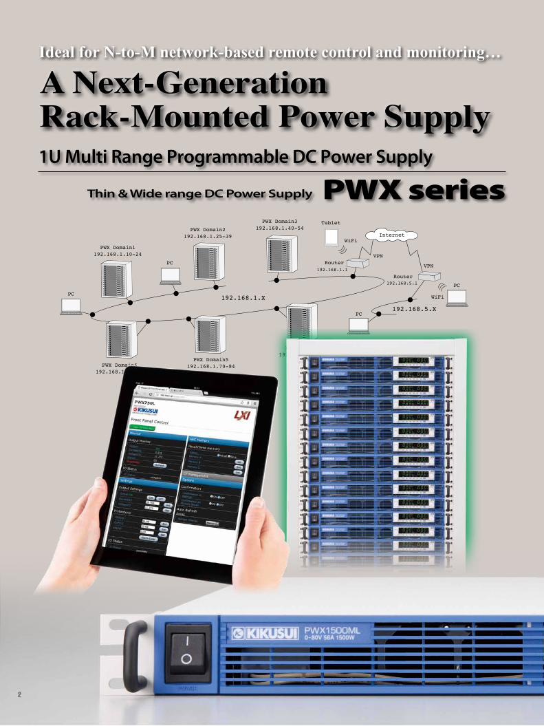
A Next-GenerationRack-Mounted Power Supply1U Multi Range Programmable DC Power Supply
Thin & Wide range DC Power Supply PWX series
Ideal for N-to-M network-based remote control and monitoring…
3
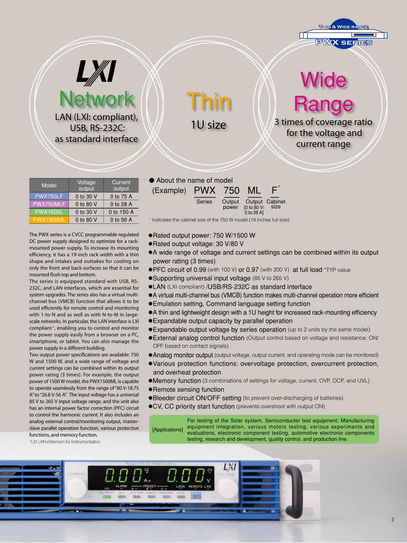
NetworkLAN (LXI: compliant),
USB, RS-232C: as standard interface
Thin1U size
lRated output power: 750 W/1500 WlRated output voltage: 30 V/80 VlA wide range of voltage and current settings can be combined within its output
power rating (3 times)lPFC circuit of 0.99 (with 100 V) or 0.97 (with 200 V) at full load *TYP valuelSupporting universal input voltage (85 V to 265 V)lLAN (LXI compliant) /USB/RS-232C as standard interfacelA virtual multi-channel bus (VMCB) function makes multi-channel operation more efficientlEmulation setting, Command language setting functionlA thin and lightweight design with a 1U height for increased rack-mounting efficiencylExpandable output capacity by parallel operationlExpandable output voltage by series operation (up to 2 units by the same model)lExternal analog control function (Output control based on voltage and resistance; ON/
OFF based on contact signals)lAnalog monitor output (output voltage, output current, and operating mode can be monitored)lVarious protection functions: overvoltage protection, overcurrent protection,
and overheat protectionlMemory function (3 combinations of settings for voltage, current, OVP, OCP, and UVL)lRemote sensing functionlBleeder circuit ON/OFF setting (to prevent over-discharging of batteries)lCV, CC priority start function (prevents overshoot with output ON)
PWX series
Thin & Wide range
The PWX series is a CVCC programmable regulated DC power supply designed to optimize for a rack-mounted power supply. To increase its mounting efficiency, it has a 19-inch rack width with a thin shape and intakes and outtakes for cooling on only the front and back surfaces so that it can be mounted flush top and bottom.The series is equipped standard with USB, RS-232C, and LAN interfaces, which are essential for system upgrades. The series also has a virtual multi-channel bus (VMCB) function that allows it to be used efficiently for remote control and monitoring with 1-to-N and as well as with N-to-M in large-scale networks. In particular, the LAN interface is LXI compliant*, enabling you to control and monitor the power supply easily from a browser on a PC, smartphone, or tablet. You can also manage the power supply in a different building.Two output power specifications are available: 750 W and 1500 W, and a wide range of voltage and current settings can be combined within its output power rating (3 times). For example, the output power of 1500 W model, the PWX1500ML is capable to operate seamlessly from the range of “80 V-18.75 A” to “26.8 V-56 A”. The input voltage has a universal 85 V to 265 V input voltage range, and the unit also has an internal power factor correction (PFC) circuit to control the harmonic current. It also includes an analog external control/monitoring output, master-slave parallel operation function, various protective functions, and memory function.*LXI: LAN eXtention for Instrumentation
[Applications]
For testing of the Solar system, Semiconductor test equipment, Manufacturing equipment integration, various motors testing, various experiments and evaluations, electronic component testing, automotive electronic components testing, research and development, quality control, and production line.
Ideal for N-to-M network-based remote control and monitoring…
WideRange
3 times of coverage ratio for the voltage and
current range
Model Voltage output
Currentoutput
PWX750LF 0 to 30 V 0 to 75 APWX750MLF 0 to 80 V 0 to 28 APWX1500L 0 to 30 V 0 to 150 A
PWX1500ML 0 to 80 V 0 to 56 A * Indicates the cabinet size of the 750 W model (19 inches full size).
l About the name of model
(Example) PWX 750 ML FSeries Output
powerOutput
[0 to 80 V/0 to 28 A]
Cabinet size
*
4
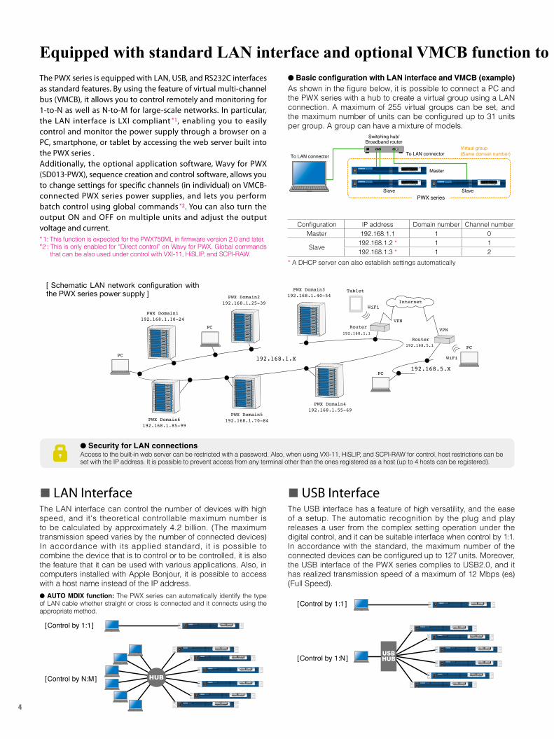
n LAN InterfaceThe LAN interface can control the number of devices with high speed, and it's theoretical controllable maximum number is to be calculated by approximately 4.2 billion. (The maximum transmission speed varies by the number of connected devices) In accordance with its applied standard, it is possible to combine the device that is to control or to be controlled, it is also the feature that it can be used with various applications. Also, in computers installed with Apple Bonjour, it is possible to access with a host name instead of the IP address.l AUTO MDIX function: The PWX series can automatically identify the type of LAN cable whether straight or cross is connected and it connects using the appropriate method.
n USB InterfaceThe USB interface has a feature of high versatility, and the ease of a setup. The automatic recognition by the plug and play releases a user from the complex setting operation under the digital control, and it can be suitable interface when control by 1:1. In accordance with the standard, the maximum number of the connected devices can be configured up to 127 units. Moreover, the USB interface of the PWX series complies to USB2.0, and it has realized transmission speed of a maximum of 12 Mbps (es) (Full Speed).
Equipped with standard LAN interface and optional VMCB function to support network-based remote control and monitoring
HUB
[Control by 1:1]
[Control by N:M]
USBHUB
[Control by 1:1]
[Control by 1:N]
l Basic configuration with LAN interface and VMCB (example)As shown in the figure below, it is possible to connect a PC and the PWX series with a hub to create a virtual group using a LAN connection. A maximum of 255 virtual groups can be set, and the maximum number of units can be configured up to 31 units per group. A group can have a mixture of models.
PC
PC
PC
VPN
VPN
WiFi
WiFiPC
Tablet
PWX Domain1192.168.1.10-24
192.168.1.X
192.168.5.X
PWX Domain2192.168.1.25-39
PWX Domain3192.168.1.40-54
192.168.1.1
192.168.5.1
PWX Domain4192.168.1.55-69
PWX Domain5192.168.1.70-84PWX Domain6
192.168.1.85-99
Router
Router
Internet
The PWX series is equipped with LAN, USB, and RS232C interfaces as standard features. By using the feature of virtual multi-channel bus (VMCB), it allows you to control remotely and monitoring for 1-to-N as well as N-to-M for large-scale networks. In particular, the LAN interface is LXI compliant *1, enabling you to easily control and monitor the power supply through a browser on a PC, smartphone, or tablet by accessing the web server built into the PWX series .Additionally, the optional application software, Wavy for PWX (SD013-PWX), sequence creation and control software, allows you to change settings for specific channels (in individual) on VMCB-connected PWX series power supplies, and lets you perform batch control using global commands *2. You can also turn the output ON and OFF on multiple units and adjust the output voltage and current.*1: This function is expected for the PWX750ML in firmware version 2.0 and later.*2 : This is only enabled for “Direct control” on Wavy for PWX. Global commands
that can be also used under control with VXI-11, HiSLIP, and SCPI-RAW.
l Security for LAN connectionsAccess to the built-in web server can be restricted with a password. Also, when using VXI-11, HiSLIP, and SCPI-RAW for control, host restrictions can be set with the IP address. It is possible to prevent access from any terminal other than the ones registered as a host (up to 4 hosts can be registered).
Configuration IP address Domain number Channel numberMaster 192.168.1.1 1 0
Slave 192.168.1.2 * 1 1192.168.1.3 * 1 2
* A DHCP server can also establish settings automatically
[ Schematic LAN network configuration with the PWX series power supply ]
Switching hub/Broadband router
Master
Virtual group (Same domain number)To LAN connector To LAN connector
Slave SlavePWX series
5
PWX series
Thin & Wide range
Equipped with standard LAN interface and optional VMCB function to support network-based remote control and monitoring
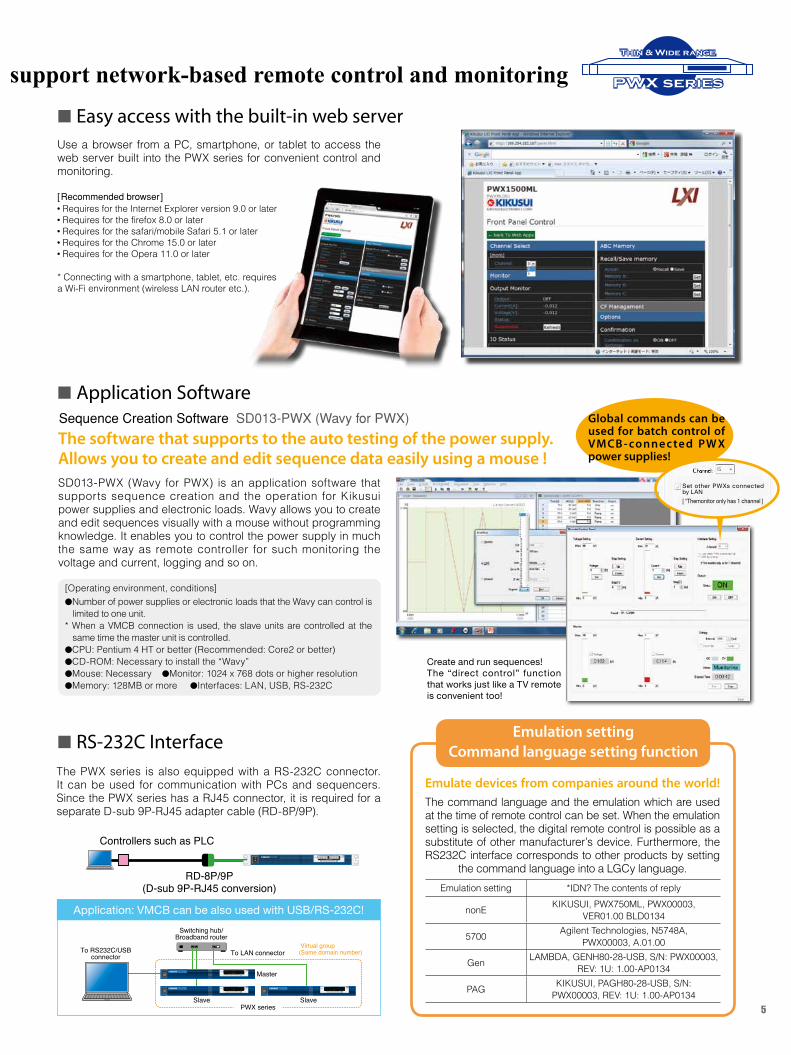
n Easy access with the built-in web serverUse a browser from a PC, smartphone, or tablet to access the web server built into the PWX series for convenient control and monitoring.
[Recommended browser] l Requires for the Internet Explorer version 9.0 or laterl Requires for the firefox 8.0 or laterl Requires for the safari/mobile Safari 5.1 or laterl Requires for the Chrome 15.0 or laterl Requires for the Opera 11.0 or later
* Connecting with a smartphone, tablet, etc. requires a Wi-Fi environment (wireless LAN router etc.).
n RS-232C InterfaceThe PWX series is also equipped with a RS-232C connector. It can be used for communication with PCs and sequencers. Since the PWX series has a RJ45 connector, it is required for a separate D-sub 9P-RJ45 adapter cable (RD-8P/9P).
Application: VMCB can be also used with USB/RS-232C!
Create and run sequences! The “direct control” function that works just like a TV remote is convenient too!
Global commands can be used for batch control of VMCB - connec ted PW X power supplies!
Emulate devices from companies around the world! The command language and the emulation which are used at the time of remote control can be set. When the emulation setting is selected, the digital remote control is possible as a substitute of other manufacturer’s device. Furthermore, the RS232C interface corresponds to other products by setting
the command language into a LGCy language.
Emulation settingCommand language setting function
n Application SoftwareSequence Creation Software SD013-PWX (Wavy for PWX)
SD013-PWX (Wavy for PWX) is an application software that supports sequence creation and the operation for Kikusui power supplies and electronic loads. Wavy allows you to create and edit sequences visually with a mouse without programming knowledge. It enables you to control the power supply in much the same way as remote controller for such monitoring the voltage and current, logging and so on.
The software that supports to the auto testing of the power supply.Allows you to create and edit sequence data easily using a mouse !
lNumber of power supplies or electronic loads that the Wavy can control is limited to one unit.
* When a VMCB connection is used, the slave units are controlled at the same time the master unit is controlled.
lCPU: Pentium 4 HT or better (Recommended: Core2 or better)lCD-ROM: Necessary to install the “Wavy”lMouse: Necessary lMonitor: 1024 x 768 dots or higher resolutionlMemory: 128MB or more lInterfaces: LAN, USB, RS-232C
[Operating environment, conditions]
To RS232C/USBconnector
Switching hub/Broadband router
Virtual group(Same domain number)
Master
Slave Slave
To LAN connector
PWX series
RD-8P/9P(D-sub 9P-RJ45 conversion)
Controllers such as PLC
Emulation setting *IDN? The contents of reply
nonE KIKUSUI, PWX750ML, PWX00003,VER01.00 BLD0134
5700 Agilent Technologies, N5748A,PWX00003, A.01.00
Gen LAMBDA, GENH80-28-USB, S/N: PWX00003,REV: 1U: 1.00-AP0134
PAG KIKUSUI, PAGH80-28-USB, S/N:PWX00003, REV: 1U: 1.00-AP0134
Set other PWXs connected by LAN [ *Themonitor only has 1 channel ]
6
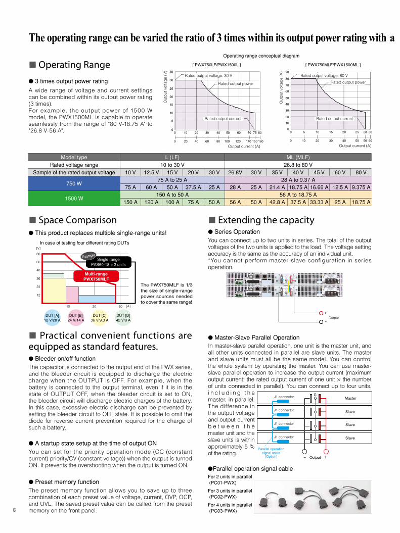
n Operating Range
l 3 times output power rating
A wide range of voltage and current settings can be combined within its output power rating (3 times).For example, the output power of 1500 W model, the PWX1500ML is capable to operate seamlessly from the range of "80 V-18.75 A" to "26.8 V-56 A".
The operating range can be varied the ratio of 3 times within its output power rating with a full range of functions that make it suitable as a test power supplyOperating range conceptual diagram
In case of testing four different rating DUTs
The PWX750MLF is 1/3 the size of single-range power sources needed to cover the same range!
Output current (A)
Out
put v
olta
ge (V
) 35
30
25
20
15
10
5
00 10 20 30 40 50 60 80
0 20 40 60 80 100 120
70
140
75
150 160
Rated output current
Rated output power
[ PWX750LF/PWX1500L ]
Rated output voltage: 30 V
Output current (A)
Out
put v
olta
ge (V
) 90
80
70
60
50
40
30
20
10
00 5 10 15 20 25 28 30
0 10 20 30 40 50 56 60
[ PWX750MLF/PWX1500ML ]
Rated output current
Rated output powerRated output voltage: 80 V
Model type L (LF) ML (MLF)Rated voltage range 10 to 30 V 26.8 to 80 V
Sample of the rated output voltage 10 V 12.5 V 15 V 20 V 30 V 26.8V 30 V 35 V 40 V 45 V 60 V 80 V
750 W75 A to 25 A 28 A to 9.37 A
75 A 60 A 50 A 37.5 A 25 A 28 A 25 A 21.4 A 18.75 A 16.66 A 12.5 A 9.375 A
1500 W150 A to 50 A 56 A to 18.75 A
150 A 120 A 100 A 75 A 50 A 56 A 50 A 42.8 A 37.5 A 33.33 A 25 A 18.75 A
DUT [A]12 V/28 A
DUT [B]24 V/14 A
DUT [C]36 V/9.3 A
DUT [D]42 V/8 A
12
24
36
48
60
80[V]
10 20 30 [A]
Single rangePAS60-18 × 2 units
Example
Multi-rangePWX750MLF
n Space Comparisonl This product replaces multiple single-range units!
n Practical convenient functions are equipped as standard features.l Bleeder on/off functionThe capacitor is connected to the output end of the PWX series, and the bleeder circuit is equipped to discharge the electric charge when the OUTPUT is OFF. For example, when the battery is connected to the output terminal, even if it is in the state of OUTPUT OFF, when the bleeder circuit is set to ON, the bleeder circuit will discharge electric charges of the battery. In this case, excessive electric discharge can be prevented by setting the bleeder circuit to OFF state. It is possible to omit the diode for reverse current prevention required for the charge of such a battery.
l A startup state setup at the time of output ON You can set for the priority operation mode (CC (constant current) priority/CV (constant voltage) ) when the output is turned ON. It prevents the overshooting when the output is turned ON.
l Preset memory functionThe preset memory function allows you to save up to three combination of each preset value of voltage, current, OVP, OCP, and UVL. The saved preset value can be called from the preset memory on the front panel.
n Extending the capacityl Series OperationYou can connect up to two units in series. The total of the output voltages of the two units is applied to the load. The voltage setting accuracy is the same as the accuracy of an individual unit. *You cannot perform master-slave configuration in series operation.
l Master-Slave Parallel OperationIn master-slave parallel operation, one unit is the master unit, and all other units connected in parallel are slave units. The master and slave units must all be the same model. You can control the whole system by operating the master. You can use master-slave parallel operation to increase the output current (maximum output current: the rated output current of one unit × the number of units connected in parallel). You can connect up to four units, i n c l u d i n g t h e master, in parallel. The difference in the output voltage and output current b e t w e e n t h e master unit and the slave units is within approximately 5 % of the rating.
Output+
-
J1 connector G
+− Output
Parallel operationsignal cable
(Option)
Master
J1 connector
J1 connector
J1 connector
Slave
Slave
Slave
lParallel operation signal cableFor 2 units in parallel (PC01-PWX)
For 3 units in parallel (PC02-PWX)
For 4 units in parallel (PC03-PWX)
7
PWX series
Thin & Wide range
The operating range can be varied the ratio of 3 times within its output power rating with a full range of functions that make it suitable as a test power supply
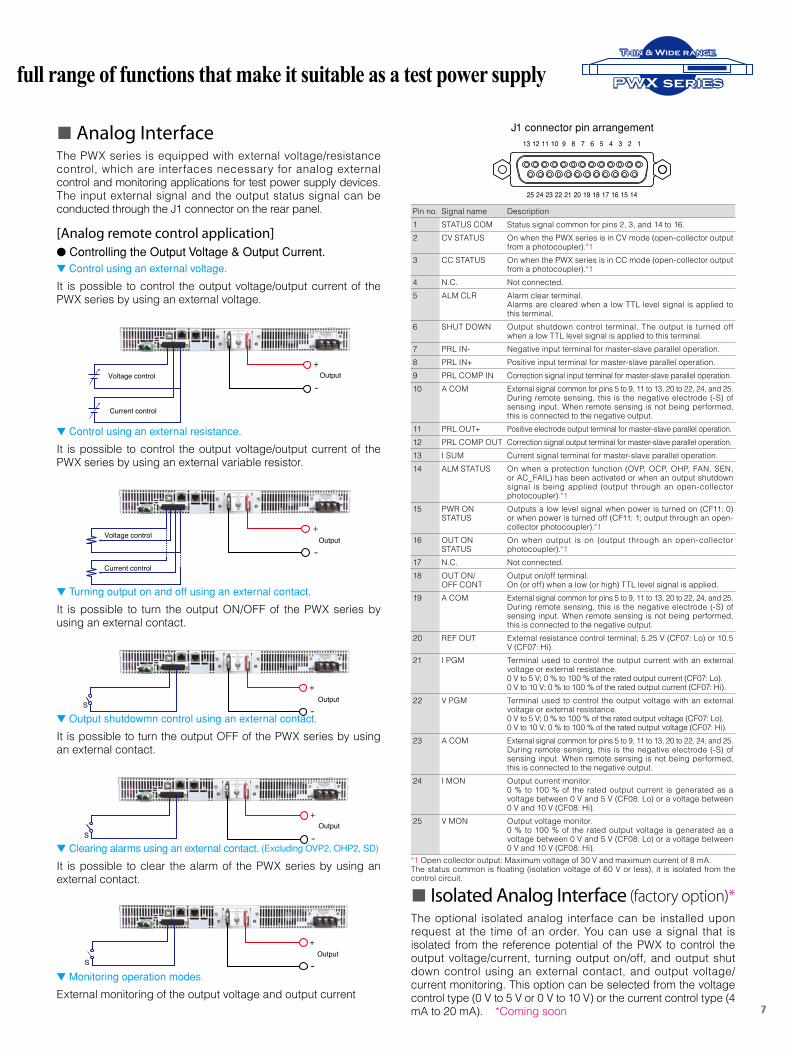
n Analog InterfaceThe PWX series is equipped with external voltage/resistance control, which are interfaces necessary for analog external control and monitoring applications for test power supply devices. The input external signal and the output status signal can be conducted through the J1 connector on the rear panel.
[Analog remote control application]l Controlling the Output Voltage & Output Current.t Control using an external voltage.
It is possible to control the output voltage/output current of the PWX series by using an external voltage.
t Control using an external resistance.
It is possible to control the output voltage/output current of the PWX series by using an external variable resistor.
t Turning output on and off using an external contact.
It is possible to turn the output ON/OFF of the PWX series by using an external contact.
t Output shutdowmn control using an external contact.
It is possible to turn the output OFF of the PWX series by using an external contact.
t Clearing alarms using an external contact. (Excluding OVP2, OHP2, SD)
It is possible to clear the alarm of the PWX series by using an external contact.
t Monitoring operation modes
External monitoring of the output voltage and output current
Voltage control
Current control
Output+
-
Voltage control
Current control
Output+
-
OutputS
+
-
OutputS
+
-
OutputS
+
-
n Isolated Analog Interface (factory option)*The optional isolated analog interface can be installed upon request at the time of an order. You can use a signal that is isolated from the reference potential of the PWX to control the output voltage/current, turning output on/off, and output shut down control using an external contact, and output voltage/current monitoring. This option can be selected from the voltage control type (0 V to 5 V or 0 V to 10 V) or the current control type (4 mA to 20 mA). *Coming soon
Pin no. Signal name Description1 STATUS COM Status signal common for pins 2, 3, and 14 to 16.2 CV STATUS On when the PWX series is in CV mode (open-collector output
from a photocoupler).*13 CC STATUS On when the PWX series is in CC mode (open-collector output
from a photocoupler).*14 N.C. Not connected.5 ALM CLR Alarm clear terminal.
Alarms are cleared when a low TTL level signal is applied to this terminal.
6 SHUT DOWN Output shutdown control terminal. The output is turned off when a low TTL level signal is applied to this terminal.
7 PRL IN- Negative input terminal for master-slave parallel operation.8 PRL IN+ Positive input terminal for master-slave parallel operation.9 PRL COMP IN Correction signal input terminal for master-slave parallel operation.10 A COM External signal common for pins 5 to 9, 11 to 13, 20 to 22, 24, and 25.
During remote sensing, this is the negative electrode (-S) of sensing input. When remote sensing is not being performed, this is connected to the negative output.
11 PRL OUT+ Positive electrode output terminal for master-slave parallel operation.12 PRL COMP OUT Correction signal output terminal for master-slave parallel operation.13 I SUM Current signal terminal for master-slave parallel operation.14 ALM STATUS On when a protection function (OVP, OCP, OHP, FAN, SEN,
or AC_FAIL) has been activated or when an output shutdown signal is being applied (output through an open-collector photocoupler).*1
15 PWR ON STATUS
Outputs a low level signal when power is turned on (CF11: 0) or when power is turned off (CF11: 1; output through an open-collector photocoupler).*1
16 OUT ON STATUS
On when output is on (output through an open-collector photocoupler).*1
17 N.C. Not connected.18 OUT ON/
OFF CONT Output on/off terminal.On (or off) when a low (or high) TTL level signal is applied.
19 A COM External signal common for pins 5 to 9, 11 to 13, 20 to 22, 24, and 25.During remote sensing, this is the negative electrode (-S) of sensing input. When remote sensing is not being performed, this is connected to the negative output.
20 REF OUT External resistance control terminal; 5.25 V (CF07: Lo) or 10.5 V (CF07: Hi).
21 I PGM Terminal used to control the output current with an external voltage or external resistance.0 V to 5 V; 0 % to 100 % of the rated output current (CF07: Lo).0 V to 10 V; 0 % to 100 % of the rated output current (CF07: Hi).
22 V PGM Terminal used to control the output voltage with an external voltage or external resistance.0 V to 5 V; 0 % to 100 % of the rated output voltage (CF07: Lo).0 V to 10 V; 0 % to 100 % of the rated output voltage (CF07: Hi).
23 A COM External signal common for pins 5 to 9, 11 to 13, 20 to 22, 24, and 25.During remote sensing, this is the negative electrode (-S) of sensing input. When remote sensing is not being performed, this is connected to the negative output.
24 I MON Output current monitor.0 % to 100 % of the rated output current is generated as a voltage between 0 V and 5 V (CF08: Lo) or a voltage between 0 V and 10 V (CF08: Hi).
25 V MON Output voltage monitor.0 % to 100 % of the rated output voltage is generated as a voltage between 0 V and 5 V (CF08: Lo) or a voltage between 0 V and 10 V (CF08: Hi).
*1 Open collector output: Maximum voltage of 30 V and maximum current of 8 mA.The status common is floating (isolation voltage of 60 V or less), it is isolated from the control circuit.
12345678910111213
141516171819202122232425
J1 connector pin arrangement
8
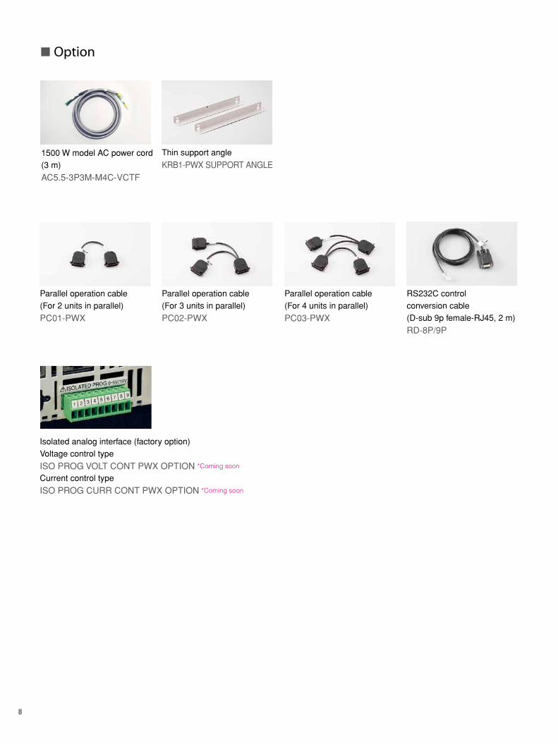
n Option
Parallel operation cable(For 2 units in parallel)
PC01-PWX
Parallel operation cable(For 3 units in parallel)
PC02-PWX
Parallel operation cable(For 4 units in parallel)
PC03-PWX
RS232C controlconversion cable(D-sub 9p female-RJ45, 2 m)
RD-8P/9P
Thin support angle
KRB1-PWX SUPPORT ANGLE1500 W model AC power cord (3 m)
AC5.5-3P3M-M4C-VCTF
Isolated analog interface (factory option)Voltage control type
ISO PROG VOLT CONT PWX OPTION *Coming soon
Current control type
ISO PROG CURR CONT PWX OPTION *Coming soon
9
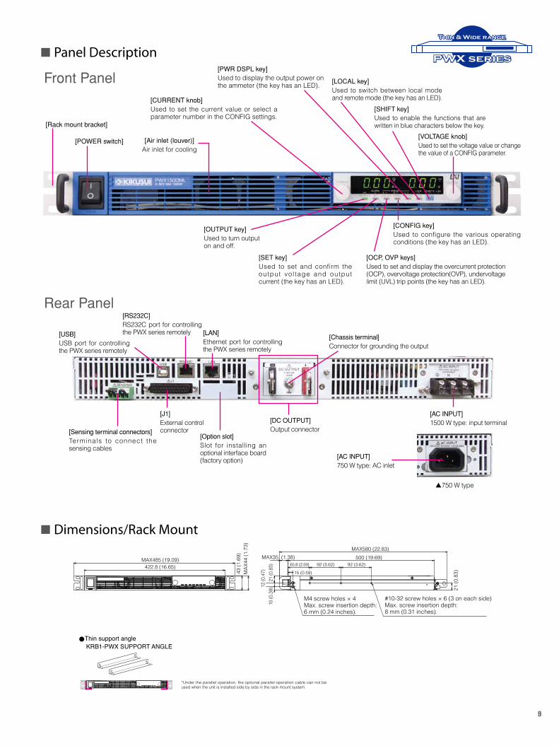
n Panel Description
n Dimensions/Rack Mount
Thin support angle KRB1-PWX SUPPORT ANGLE
*Under the parallel operation, the optional parallel operation cable can not be used when the unit is installed side by side in the rack mount system.
MAX580 (22.83)MAX35 (1.38) 500 (19.69)
65.8 (2.59)MAX485 (19.09)
422.8 (16.65) 92 (3.62)
15 (0.59)
92 (3.62)
21 (0
.83)
43 (1
.69)
MAX
44 (1
.73)
10 (0
.39)
21 (0
.83)
12 (0
.47)
M4 screw holes × 4Max. screw insertion depth:6 mm (0.24 inches).
#10-32 screw holes × 6 (3 on each side)Max. screw insertion depth:8 mm (0.31 inches).
[POWER switch]
[CURRENT knob]Used to set the current value or select a parameter number in the CONFIG settings.
[OUTPUT key]Used to turn output on and off.
[SET key]Used to set and confirm the output vol tage and output current (the key has an LED).
[OCP, OVP keys]Used to set and display the overcurrent protection (OCP), overvoltage protection(OVP), undervoltage limit (UVL) trip points (the key has an LED).
[CONFIG key]Used to configure the various operating conditions (the key has an LED).
[PWR DSPL key]Used to display the output power on the ammeter (the key has an LED). [LOCAL key]
Used to switch between local mode and remote mode (the key has an LED).
[SHIFT key]Used to enable the functions that are written in blue characters below the key.
[VOLTAGE knob]Used to set the voltage value or change the value of a CONFIG parameter.
[Air inlet (louver)]Air inlet for cooling
[Rack mount bracket]
[DC OUTPUT]Output connector
[RS232C]RS232C port for controlling the PWX series remotely [LAN]
Ethernet port for controlling the PWX series remotely
[USB]USB port for controlling the PWX series remotely
[Sensing terminal connectors]Terminals to connect the sensing cables
[AC INPUT]1500 W type: input terminal
[AC INPUT]750 W type: AC inlet
Front Panel
Rear Panel
[J1]External control connector
[Option slot]Slot for installing an optional interface board (factory option)
[Chassis terminal]Connector for grounding the output
p750 W type
PWX series
Thin & Wide range
10
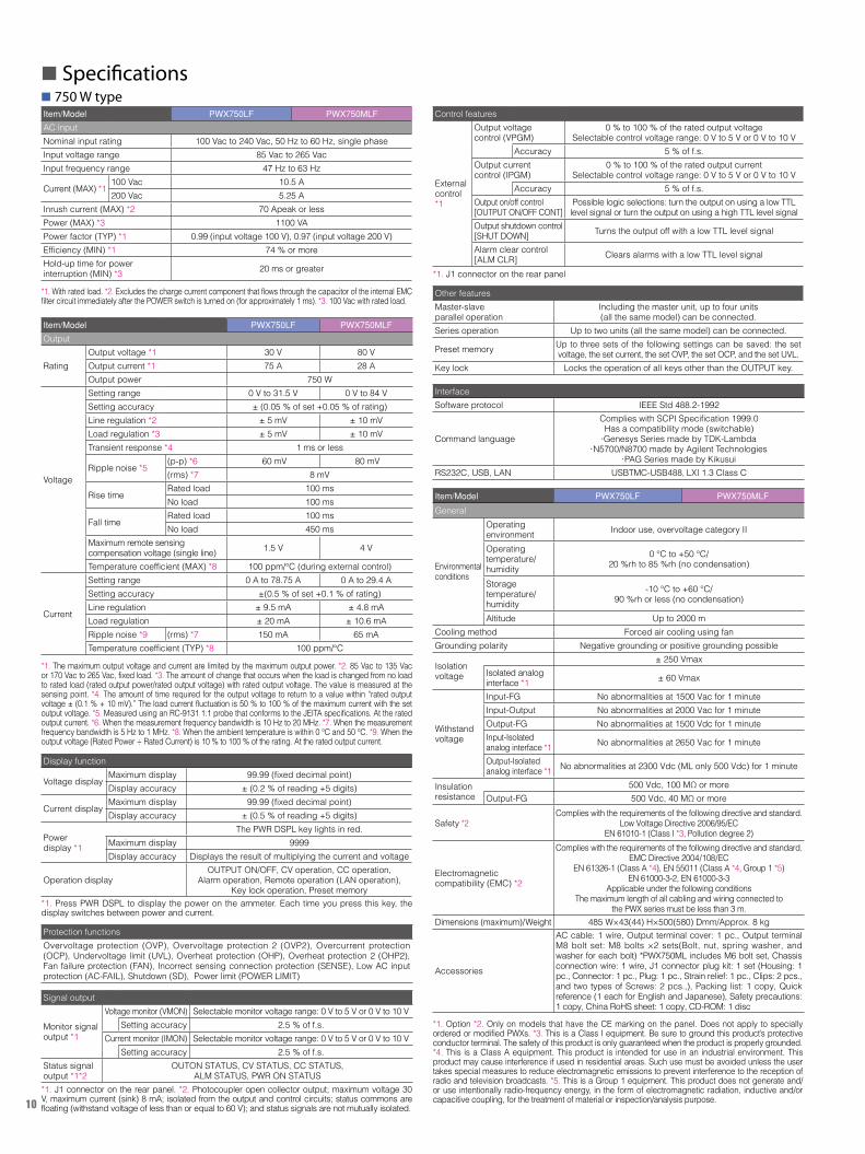
n 750 W type
n Specifications
Item/Model PWX750LF PWX750MLF
AC inputNominal input rating 100 Vac to 240 Vac, 50 Hz to 60 Hz, single phaseInput voltage range 85 Vac to 265 VacInput frequency range 47 Hz to 63 Hz
Current (MAX) *1100 Vac 10.5 A200 Vac 5.25 A
Inrush current (MAX) *2 70 Apeak or lessPower (MAX) *3 1100 VAPower factor (TYP) *1 0.99 (input voltage 100 V), 0.97 (input voltage 200 V)Efficiency (MIN) *1 74 % or moreHold-up time for power interruption (MIN) *3 20 ms or greater
*1. With rated load. *2. Excludes the charge current component that flows through the capacitor of the internal EMC filter circuit immediately after the POWER switch is turned on (for approximately 1 ms). *3. 100 Vac with rated load.
Item/Model PWX750LF PWX750MLF
Output
RatingOutput voltage *1 30 V 80 VOutput current *1 75 A 28 AOutput power 750 W
Voltage
Setting range 0 V to 31.5 V 0 V to 84 VSetting accuracy ± (0.05 % of set +0.05 % of rating)Line regulation *2 ± 5 mV ± 10 mVLoad regulation *3 ± 5 mV ± 10 mVTransient response *4 1 ms or less
Ripple noise *5(p-p) *6 60 mV 80 mV(rms) *7 8 mV
Rise timeRated load 100 msNo load 100 ms
Fall timeRated load 100 msNo load 450 ms
Maximum remote sensingcompensation voltage (single line) 1.5 V 4 V
Temperature coefficient (MAX) *8 100 ppm/°C (during external control)
Current
Setting range 0 A to 78.75 A 0 A to 29.4 ASetting accuracy ±(0.5 % of set +0.1 % of rating)Line regulation ± 9.5 mA ± 4.8 mALoad regulation ± 20 mA ± 10.6 mARipple noise *9 (rms) *7 150 mA 65 mATemperature coefficient (TYP) *8 100 ppm/°C
*1. The maximum output voltage and current are limited by the maximum output power. *2. 85 Vac to 135 Vac or 170 Vac to 265 Vac, fixed load. *3. The amount of change that occurs when the load is changed from no load to rated load (rated output power/rated output voltage) with rated output voltage. The value is measured at the sensing point. *4. The amount of time required for the output voltage to return to a value within “rated output voltage ± (0.1 % + 10 mV).” The load current fluctuation is 50 % to 100 % of the maximum current with the set output voltage. *5. Measured using an RC-9131 1:1 probe that conforms to the JEITA specifications. At the rated output current. *6. When the measurement frequency bandwidth is 10 Hz to 20 MHz. *7. When the measurement frequency bandwidth is 5 Hz to 1 MHz. *8. When the ambient temperature is within 0 °C and 50 °C. *9. When the output voltage (Rated Power ÷ Rated Current) is 10 % to 100 % of the rating. At the rated output current.
Display function
Voltage displayMaximum display 99.99 (fixed decimal point)Display accuracy ± (0.2 % of reading +5 digits)
Current displayMaximum display 99.99 (fixed decimal point)Display accuracy ± (0.5 % of reading +5 digits)
Powerdisplay *1
The PWR DSPL key lights in red.Maximum display 9999Display accuracy Displays the result of multiplying the current and voltage
Operation displayOUTPUT ON/OFF, CV operation, CC operation,
Alarm operation, Remote operation (LAN operation),Key lock operation, Preset memory
*1. Press PWR DSPL to display the power on the ammeter. Each time you press this key, the display switches between power and current.
Protection functionsOvervoltage protection (OVP), Overvoltage protection 2 (OVP2), Overcurrent protection (OCP), Undervoltage limit (UVL), Overheat protection (OHP), Overheat protection 2 (OHP2), Fan failure protection (FAN), Incorrect sensing connection protection (SENSE), Low AC input protection (AC-FAIL), Shutdown (SD), Power limit (POWER LIMIT)
Signal output
Monitor signal output *1
Voltage monitor (VMON) Selectable monitor voltage range: 0 V to 5 V or 0 V to 10 VSetting accuracy 2.5 % of f.s.
Current monitor (IMON) Selectable monitor voltage range: 0 V to 5 V or 0 V to 10 VSetting accuracy 2.5 % of f.s.
Status signal output *1*2
OUTON STATUS, CV STATUS, CC STATUS,ALM STATUS, PWR ON STATUS
*1. J1 connector on the rear panel. *2. Photocoupler open collector output; maximum voltage 30 V, maximum current (sink) 8 mA; isolated from the output and control circuits; status commons are floating (withstand voltage of less than or equal to 60 V); and status signals are not mutually isolated.
Control features
Externalcontrol*1
Output voltagecontrol (VPGM)
0 % to 100 % of the rated output voltageSelectable control voltage range: 0 V to 5 V or 0 V to 10 V
Accuracy 5 % of f.s.Output currentcontrol (IPGM)
0 % to 100 % of the rated output currentSelectable control voltage range: 0 V to 5 V or 0 V to 10 V
Accuracy 5 % of f.s.Output on/off control[OUTPUT ON/OFF CONT]
Possible logic selections: turn the output on using a low TTLlevel signal or turn the output on using a high TTL level signal
Output shutdown control[SHUT DOWN] Turns the output off with a low TTL level signal
Alarm clear control[ALM CLR] Clears alarms with a low TTL level signal
*1. J1 connector on the rear panel
Other featuresMaster-slave parallel operation
Including the master unit, up to four units(all the same model) can be connected.
Series operation Up to two units (all the same model) can be connected.
Preset memory Up to three sets of the following settings can be saved: the set voltage, the set current, the set OVP, the set OCP, and the set UVL.
Key lock Locks the operation of all keys other than the OUTPUT key.
InterfaceSoftware protocol IEEE Std 488.2-1992
Command language
Complies with SCPI Specification 1999.0Has a compatibility mode (switchable)
l Genesys Series made by TDK-Lambdal N5700/N8700 made by Agilent Technologies
l PAG Series made by KikusuiRS232C, USB, LAN USBTMC-USB488, LXI 1.3 Class C
*1. Option *2. Only on models that have the CE marking on the panel. Does not apply to specially ordered or modified PWXs. *3. This is a Class I equipment. Be sure to ground this product’s protective conductor terminal. The safety of this product is only guaranteed when the product is properly grounded. *4. This is a Class A equipment. This product is intended for use in an industrial environment. This product may cause interference if used in residential areas. Such use must be avoided unless the user takes special measures to reduce electromagnetic emissions to prevent interference to the reception of radio and television broadcasts. *5. This is a Group 1 equipment. This product does not generate and/or use intentionally radio-frequency energy, in the form of electromagnetic radiation, inductive and/or capacitive coupling, for the treatment of material or inspection/analysis purpose.
Item/Model PWX750LF PWX750MLF
General
Environmental conditions
Operatingenvironment Indoor use, overvoltage category II
Operatingtemperature/humidity
0 ℃ to +50 °C/20 %rh to 85 %rh (no condensation)
Storagetemperature/humidity
-10 °C to +60 °C/90 %rh or less (no condensation)
Altitude Up to 2000 mCooling method Forced air cooling using fanGrounding polarity Negative grounding or positive grounding possible
Isolationvoltage
± 250 VmaxIsolated analog interface *1 ± 60 Vmax
Withstand voltage
Input-FG No abnormalities at 1500 Vac for 1 minuteInput-Output No abnormalities at 2000 Vac for 1 minuteOutput-FG No abnormalities at 1500 Vdc for 1 minuteInput-Isolated analog interface *1 No abnormalities at 2650 Vac for 1 minute
Output-Isolated analog interface *1 No abnormalities at 2300 Vdc (ML only 500 Vdc) for 1 minute
Insulation resistance
500 Vdc, 100 MΩ or moreOutput-FG 500 Vdc, 40 MΩ or more
Safety *2Complies with the requirements of the following directive and standard.
Low Voltage Directive 2006/95/ECEN 61010-1 (Class I *3, Pollution degree 2)
Electromagneticcompatibility (EMC) *2
Complies with the requirements of the following directive and standard.EMC Directive 2004/108/EC
EN 61326-1 (Class A *4), EN 55011 (Class A *4, Group 1 *5) EN 61000-3-2, EN 61000-3-3
Applicable under the following conditionsThe maximum length of all cabling and wiring connected to
the PWX series must be less than 3 m.Dimensions (maximum)/Weight 485 W×43(44) H×500(580) Dmm/Approx. 8 kg
Accessories
AC cable: 1 wire, Output terminal cover: 1 pc., Output terminal M8 bolt set: M8 bolts ×2 sets(Bolt, nut, spring washer, and washer for each bolt) *PWX750ML includes M6 bolt set, Chassis connection wire: 1 wire, J1 connector plug kit: 1 set (Housing: 1 pc., Connector: 1 pc., Plug: 1 pc., Strain relief: 1 pc., Clips: 2 pcs., and two types of Screws: 2 pcs.,), Packing list: 1 copy, Quick reference (1 each for English and Japanese), Safety precautions: 1 copy, China RoHS sheet: 1 copy, CD-ROM: 1 disc
11
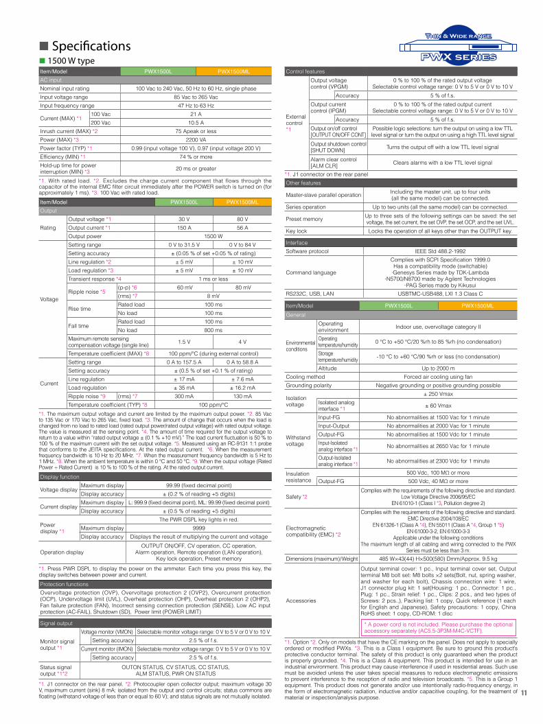
n 1500 W type
n Specifications
Item/Model PWX1500L PWX1500ML
AC inputNominal input rating 100 Vac to 240 Vac, 50 Hz to 60 Hz, single phaseInput voltage range 85 Vac to 265 VacInput frequency range 47 Hz to 63 Hz
Current (MAX) *1100 Vac 21 A200 Vac 10.5 A
Inrush current (MAX) *2 75 Apeak or lessPower (MAX) *3 2200 VAPower factor (TYP) *1 0.99 (input voltage 100 V), 0.97 (input voltage 200 V)Efficiency (MIN) *1 74 % or moreHold-up time for power interruption (MIN) *3 20 ms or greater
*1. With rated load. *2. Excludes the charge current component that flows through the capacitor of the internal EMC filter circuit immediately after the POWER switch is turned on (for approximately 1 ms). *3. 100 Vac with rated load.Item/Model PWX1500L PWX1500ML
Output
RatingOutput voltage *1 30 V 80 VOutput current *1 150 A 56 AOutput power 1500 W
Voltage
Setting range 0 V to 31.5 V 0 V to 84 VSetting accuracy ± (0.05 % of set +0.05 % of rating)Line regulation *2 ± 5 mV ± 10 mVLoad regulation *3 ± 5 mV ± 10 mVTransient response *4 1 ms or less
Ripple noise *5(p-p) *6 60 mV 80 mV(rms) *7 8 mV
Rise timeRated load 100 msNo load 100 ms
Fall timeRated load 100 msNo load 800 ms
Maximum remote sensingcompensation voltage (single line) 1.5 V 4 V
Temperature coefficient (MAX) *8 100 ppm/°C (during external control)
Current
Setting range 0 A to 157.5 A 0 A to 58.8 ASetting accuracy ± (0.5 % of set +0.1 % of rating)Line regulation ± 17 mA ± 7.6 mALoad regulation ± 35 mA ± 16.2 mARipple noise *9 (rms) *7 300 mA 130 mATemperature coefficient (TYP) *8 100 ppm/°C
*1. The maximum output voltage and current are limited by the maximum output power. *2. 85 Vac to 135 Vac or 170 Vac to 265 Vac, fixed load. *3. The amount of change that occurs when the load is changed from no load to rated load (rated output power/rated output voltage) with rated output voltage. The value is measured at the sensing point. *4. The amount of time required for the output voltage to return to a value within “rated output voltage ± (0.1 % +10 mV).” The load current fluctuation is 50 % to 100 % of the maximum current with the set output voltage. *5. Measured using an RC-9131 1:1 probe that conforms to the JEITA specifications. At the rated output current. *6. When the measurement frequency bandwidth is 10 Hz to 20 MHz. *7. When the measurement frequency bandwidth is 5 Hz to 1 MHz. *8. When the ambient temperature is within 0 °C and 50 °C. *9. When the output voltage (Rated Power ÷ Rated Current) is 10 % to 100 % of the rating. At the rated output current. Display function
Voltage displayMaximum display 99.99 (fixed decimal point)Display accuracy ± (0.2 % of reading +5 digits)
Current displayMaximum display L: 999.9 (fixed decimal point), ML: 99.99 (fixed decimal point)Display accuracy ± (0.5 % of reading +5 digits)
Powerdisplay *1
The PWR DSPL key lights in red.Maximum display 9999Display accuracy Displays the result of multiplying the current and voltage
Operation displayOUTPUT ON/OFF, CV operation, CC operation,
Alarm operation, Remote operation (LAN operation),Key lock operation, Preset memory
*1. Press PWR DSPL to display the power on the ammeter. Each time you press this key, the display switches between power and current.Protection functionsOvervoltage protection (OVP), Overvoltage protection 2 (OVP2), Overcurrent protection (OCP), Undervoltage limit (UVL), Overheat protection (OHP), Overheat protection 2 (OHP2), Fan failure protection (FAN), Incorrect sensing connection protection (SENSE), Low AC input protection (AC-FAIL), Shutdown (SD), Power limit (POWER LIMIT)
Signal output
Monitor signal output *1
Voltage monitor (VMON) Selectable monitor voltage range: 0 V to 5 V or 0 V to 10 VSetting accuracy 2.5 % of f.s.
Current monitor (IMON) Selectable monitor voltage range: 0 V to 5 V or 0 V to 10 VSetting accuracy 2.5 % of f.s.
Status signal output *1*2
OUTON STATUS, CV STATUS, CC STATUS,ALM STATUS, PWR ON STATUS
*1. J1 connector on the rear panel. *2. Photocoupler open collector output; maximum voltage 30 V, maximum current (sink) 8 mA; isolated from the output and control circuits; status commons are floating (withstand voltage of less than or equal to 60 V); and status signals are not mutually isolated.
Control features
Externalcontrol*1
Output voltagecontrol (VPGM)
0 % to 100 % of the rated output voltageSelectable control voltage range: 0 V to 5 V or 0 V to 10 V
Accuracy 5 % of f.s.Output currentcontrol (IPGM)
0 % to 100 % of the rated output currentSelectable control voltage range: 0 V to 5 V or 0 V to 10 V
Accuracy 5 % of f.s.Output on/off control[OUTPUT ON/OFF CONT]
Possible logic selections: turn the output on using a low TTLlevel signal or turn the output on using a high TTL level signal
Output shutdown control[SHUT DOWN] Turns the output off with a low TTL level signal
Alarm clear control[ALM CLR] Clears alarms with a low TTL level signal
*1. J1 connector on the rear panelOther features
Master-slave parallel operation Including the master unit, up to four units(all the same model) can be connected.
Series operation Up to two units (all the same model) can be connected.
Preset memory Up to three sets of the following settings can be saved: the set voltage, the set current, the set OVP, the set OCP, and the set UVL.
Key lock Locks the operation of all keys other than the OUTPUT key.
InterfaceSoftware protocol IEEE Std 488.2-1992
Command language
Complies with SCPI Specification 1999.0Has a compatibility mode (switchable)
l Genesys Series made by TDK-Lambdal N5700/N8700 made by Agilent Technologies
l PAG Series made by KikusuiRS232C, USB, LAN USBTMC-USB488, LXI 1.3 Class C
*1. Option *2. Only on models that have the CE marking on the panel. Does not apply to specially ordered or modified PWXs. *3. This is a Class I equipment. Be sure to ground this product’s protective conductor terminal. The safety of this product is only guaranteed when the product is properly grounded. *4. This is a Class A equipment. This product is intended for use in an industrial environment. This product may cause interference if used in residential areas. Such use must be avoided unless the user takes special measures to reduce electromagnetic emissions to prevent interference to the reception of radio and television broadcasts. *5. This is a Group 1 equipment. This product does not generate and/or use intentionally radio-frequency energy, in the form of electromagnetic radiation, inductive and/or capacitive coupling, for the treatment of material or inspection/analysis purpose.
Item/Model PWX1500L PWX1500ML
General
Environmental conditions
Operatingenvironment Indoor use, overvoltage category II
Operatingtemperature/humidity 0 ℃ to +50 °C/20 %rh to 85 %rh (no condensation)
Storagetemperature/humidity -10 °C to +60 °C/90 %rh or less (no condensation)
Altitude Up to 2000 mCooling method Forced air cooling using fanGrounding polarity Negative grounding or positive grounding possible
Isolationvoltage
± 250 VmaxIsolated analog interface *1 ± 60 Vmax
Withstand voltage
Input-FG No abnormalities at 1500 Vac for 1 minuteInput-Output No abnormalities at 2000 Vac for 1 minuteOutput-FG No abnormalities at 1500 Vdc for 1 minuteInput-Isolated analog interface *1 No abnormalities at 2650 Vac for 1 minute
Output-Isolated analog interface *1 No abnormalities at 2300 Vdc for 1 minute
Insulation resistance
500 Vdc, 100 MΩ or moreOutput-FG 500 Vdc, 40 MΩ or more
Safety *2Complies with the requirements of the following directive and standard.
Low Voltage Directive 2006/95/ECEN 61010-1 (Class I *3, Pollution degree 2)
Electromagneticcompatibility (EMC) *2
Complies with the requirements of the following directive and standard.EMC Directive 2004/108/EC
EN 61326-1 (Class A *4), EN 55011 (Class A *4, Group 1 *5) EN 61000-3-2, EN 61000-3-3
Applicable under the following conditionsThe maximum length of all cabling and wiring connected to the PWX
Series must be less than 3 m.Dimensions (maximum)/Weight 485 W×43(44) H×500(580) Dmm/Approx. 9.5 kg
Accessories
Output terminal cover: 1 pc., Input terminal cover set, Output terminal M8 bolt set: M8 bolts ×2 sets(Bolt, nut, spring washer, and washer for each bolt), Chassis connection wire: 1 wire, J1 connector plug kit: 1 set(Housing: 1 pc., Connector: 1 pc., Plug: 1 pc., Strain relief: 1 pc., Clips: 2 pcs., and two types of Screws: 2 pcs.,), Packing list: 1 copy, Quick reference (1 each for English and Japanese), Safety precautions: 1 copy, China RoHS sheet: 1 copy, CD-ROM: 1 disc
PWX series
Thin & Wide range
* A power cord is not included. Please purchase the optional accessory separately (AC5.5-3P3M-M4C-VCTF).
Printed in Japan Issue: Feb.2013 201302PDFEU11
■ All products contained in this catalogue are equipment and devices that are premised on use under the supervision of qualified personnel, and are not designed or produced for home-use or use by general consumers. ■ Specifications, design and so forth are subject to change without prior notice to improve the quality. ■ Product names and prices are subject to change and production may be discontinued when necessary. ■ Product names, company names and brand names contained in this catalogue represent the respective registered trade name or trade mark. ■ Colors, textures and so forth of photographs shown in this catalogue may differ from actual products due to a limited fidelity in printing. ■ Although every effort has been made to provide the information as accurate as possible for this catalogue, certain details have unavoidably been omitted due to limitations in space. ■ If you find any misprints or errors in this catalogue, it would be appreciated if you would inform us. ■ Please contact our distributors to confirm specifications, price, accessories or anything that may be unclear when placing an order or concluding a purchasing agreement.
lDistributor/Representative
530 Lakeside Drive, Suite#180, Sunnyvale, CA 94085, U.S.A.Phone : 408-733-3432 Facsimile : 408-733-1814
www.kikusuiamerica.com1-877-876-2807
www.kikusui.cnRoom, B/C,12F, Majesty Bld, No.138, Pudong Ave, Shanghai City Phone : 021-5887-9067 Facsimile : 021-5887-9069
PWX series
Thin & Wide range
Product Model Remark
1500 W model AC power cord AC5.5-3P3M-M4C-VCTF 3 m
Thin support angle KRB1-PWX SUPPORT ANGLE For our cosmetic rack KRC/KRO Series 1U type cohesive packaging
Parallel operation cable
PC01-PWX For 2 units in parallel
PC02-PWX For 3 units in parallel
PC03-PWX For 4 units in parallel
RS232C control conversion cable RD-8P/9P D-sub 9P to famale-RJ45
Isolated analog interfaceVoltage control type Factory option. Coming soon
Current control type Factory option. Coming soon
Sequence Creation Software SD013-PWX (Wavy for PWX )
l Option
Type Model Voltage output Current output
750 WPWX750LF 0 to 30 V 0 to 75 A
PWX750MLF 0 to 80 V 0 to 28 A
1500 WPWX1500L 0 to 30 V 0 to 150 A
PWX1500ML 0 to 80 V 0 to 56 A
n Order Information
l Lineup