pwm
3
2011 International Conference on Electronic &Mechanical Engineering and Information Technology PWM Speed Control System of DC motor Based on AT89S51 Zhijun Liu School of Electrical and Information Engineering Liaoning Institute of Science and Technology Benxi, China [email protected] Lianzhi Jiang School of Electrical and Information Engineering Liaoning Institute of Science and Technology Benxi, China [email protected] Keywords-AT89S51; DC motor; PWM Abstract-This paper presents a new approach of DC motor PWM speed control, using microcomputer as controller, after discussing conventional cascade speed control. It introduces the principle of DC motor PWM speed control and the details of the realization of the approach base on AT89S51 single-chip microcomputer. Different duty cycle quadrate waves are produced by the PI of AT89S51. Different speed grades and the direction are depended on different buttons. Experiments have proved that this system is of higher performance. I. INTRODUCTION In recent years, with scientific and technological progress and social development, the electronic technology is developing rapidly, to achieve the portability and low cost and energy efficient, and the noise limit, a DC motor is used widely, so, the study of DC motor speed adjustablel'<' is more practical significance. The traditional method of control speed was that the resistance is strung in the rotor circuit or adjust the voltage of electrical machinery circuit , the two methods is easy, but they exist some shortcomings: The smooth character is bad and the characteristic is soft in low speed ,The motor speed will be changed larger when the load is changed; The motor speed is very hard to get a low when the load is light ;The larger the I resistance are, the greater its losses are, the Efficiency reduce noticeably. Therefore, a new kind of speed control method is called PWM(pulse width modulation) speed regulating system[3] has been widely used in the motor control speed. It is being applied to every field and has been product-Frequency Converter. With the wide use of PWM technological, the power energy can make full use of and the circuit efficient is very high. This paper utilizes the timing of the microcontroller timer function, outputs analog PWM signal at the P1.0 pin, to adjust the duty cycle according to the number of different pulse high, thus to achieve the governor's role. III. PWM SR PRINCIPLE AND CIRCUIT Bridge choppert' shown in Figure 1, the equivalent circuit, allows both positive and negative direction of the motor in the SR, transistors VT 4 turn on, VT 2 , VT 3 cut off and the motor turns forward. Similarly, VT 2 , VT 3 turn off the motor rolls back. Suppose turning off , VT 4 after it has turned on seconds and then a period of dead zone, when VT 2 , VT 3 turn on for T 2 seconds, cut off it immediately. So repeatedly, at both ends of the armature voltage. Where: U a is the armature terminal voltage; la is armature current; R a is equivalent resistance of armature circuit; ¢ is each level of magnetic flux. There are so many ways to speed. For instance, armature voltage control method can be used and excitation control method, but excitation control method by the magnetic saturation in the low speed limit, at high speed by changing the restrictions to the spark and the commentator, the larger field coil inductance will affect the dynamic response, therefore armature voltage control method is often currently used. Armature voltage can be adjusted series resistance of the armature loop method, but this is inefficient, and has been replaced by the chopper, which consists of the AC power supply, AC adapter with DC rectifier circuit and then the PWM chopper the chopper. Chopper motor loss not only is small, but also gives fast dynamic response, so it is widely used. (1) II. DC MOTOR SPEED CONTROL PRINCIPLE Expression for DC motor speed (r / min) Ua-laRa n==----- C e ¢ Figure 1. Bridge chopper circuit 978-1-61284-088-8/11/$26.00 ©2011 IEEE 1301 12-14 August, 2011
Transcript of pwm

2011 International Conference on Electronic &Mechanical Engineering and Information Technology
PWM Speed Control System of DC motor Based on AT89S51
Zhijun LiuSchool of Electrical and Information Engineering
Liaoning Institute of Science and TechnologyBenxi, China
Lianzhi JiangSchool ofElectrical and Information Engineering
Liaoning Institute of Science and TechnologyBenxi, China
Keywords-AT89S51; DC motor; PWM
Abstract-This paper presents a new approach of DC motorPWM speed control, using microcomputer as controller, afterdiscussing conventional cascade speed control. It introducesthe principle of DC motor PWM speed control and the detailsof the realization of the approach base on AT89S51 single-chipmicrocomputer. Different duty cycle quadrate waves areproduced by the PI of AT89S51. Different speed grades andthe direction are depended on different buttons. Experimentshave proved that this system is of higher performance.
I. INTRODUCTION
In recent years, with scientific and technological progressand social development, the electronic technology isdeveloping rapidly, to achieve the portability and low costand energy efficient, and the noise limit, a DC motor is usedwidely, so, the study of DC motor speed adjustablel'<' ismore practical significance. The traditional method ofcontrol speed was that the resistance is strung in the rotorcircuit or adjust the voltage of electrical machinery circuit ,the two methods is easy, but they exist some shortcomings:The smooth character is bad and the characteristic is soft inlow speed ,The motor speed will be changed larger when theload is changed; The motor speed is very hard to get a lowwhen the load is light ;The larger the I resistance are, thegreater its losses are, the Efficiency reduce noticeably.Therefore, a new kind of speed control method is calledPWM(pulse width modulation) speed regulating system[3]has been widely used in the motor control speed. It is beingapplied to every field and has been product-FrequencyConverter. With the wide use of PWM technological, thepower energy can make full use of and the circuit efficient isvery high. This paper utilizes the timing of themicrocontroller timer function, outputs analog PWM signalat the P1.0 pin, to adjust the duty cycle according to thenumber of different pulse high, thus to achieve thegovernor's role.
III. PWM SR PRINCIPLE AND CIRCUIT
Bridge choppert' shown in Figure 1, the equivalentcircuit, allows both positive and negative direction of the
motor in the SR, transistors V~,VT4 turn on, VT2 , VT3 cut
off and the motor turns forward. Similarly, VT2 , VT3 turn
off the motor rolls back. Suppose turning off V~ ,VT4 after
it has turned on ~ seconds and then a period of dead zone,
when VT2 , VT3 turn on for T2 seconds, cut off it
immediately. So repeatedly, at both ends of the armaturevoltage.
Where: Ua is the armature terminal voltage; la is
armature current; Ra is equivalent resistance of armature
circuit; ¢ is each level of magnetic flux.
There are so many ways to speed. For instance, armaturevoltage control method can be used and excitation controlmethod, but excitation control method by the magneticsaturation in the low speed limit, at high speed by changingthe restrictions to the spark and the commentator, the largerfield coil inductance will affect the dynamic response,therefore armature voltage control method is often currentlyused.
Armature voltage can be adjusted series resistance of thearmature loop method, but this is inefficient, and has beenreplaced by the chopper, which consists of the AC powersupply, AC adapter with DC rectifier circuit and then thePWM chopper the chopper. Chopper motor loss not only issmall, but also gives fast dynamic response, so it is widelyused.
(1)
II. DC MOTOR SPEED CONTROL PRINCIPLE
Expression for DC motor speed (r / min)
Ua-laRan==-----
Ce¢
Figure 1. Bridge chopper circuit
978-1-61284-088-8/11/$26.00 ©2011 IEEE 1301 12-14 August, 2011

Waveform is shown in Figure 2.
Va
forward, key 4 the fastest .There are 4 levels, while touchingthe No. 5,6,7,8 button, the motor turns back. Therefore theduty cycle a ranges from 1/ 8 to 8 / 8 .
V"!lOOk
Figure 4. the number of different high pulse
3a ==-
8
J
B. Pl. 0 pin realization ofthe output waveform
There are two timer/counters TO and Tl inside AT89S51,in whichTO is set to work 1, counted every 16 bit. At thismoment, the mode value of TO is 65536, the system of thetime period T is 1 f.1S , then the initial value[8-1O] TOis:
TO = 65536 _!...- = 65536 _ 30msT If.1S (3)
== 35536 == 8ADOHTherefore THO = 8AH; TLO = ODOHTO timer is initialized as following:
MOV TMOD, # 01HMOV THO, # 8AHMOV TLO, # ODOHSetb TROSetb ETOSetb EA
Figure 3. Single-chip microcomputer control speed principle
A PI.l
T P12
Assuming a pulse is 30ms, a square wave pulse of 8cycles is period of 240ms. Setting the frequency of AT89S51is 11.0952MHZ, when the pl.0 pin outputs a high level in aperiod, the duty cycle is a == 1/8 , the motor reverses in
high speed. When a == 0.5 , the motor stops running.
When a == 5 / 8 , the motor runs at low speed. When a == 1,the motor runs forward at full speed. As is shown in Figure 4.
(2)
tT
Figure 2. the armature voltage waveform
U = T[Ud _ TZUd T[ - (T - T[)Ud
a T T T
2T -T== 1 Ud == (2a -l)Ud
TFor a is the duty cycle 0 < a < 1 so
- U d < U a < +Ua : change the size of U a by changing
the size of a . When 0 < a < 0.5 ,the motor turns back.
When a == 0, the motor has the maximum speed of reversal;
when 0.5 < a < 1, the motor turns forward, as a == 1, itmoves in the maximum speed.
IV. THE SINGLE CHIP MICROCOMPUTER CONTROL DC
MOTOR CONTROL METHOD
SR ~art of the circuit controlled by AT89S51 MCVshown!" ] in Figure 3, S is the motor start switch, outputwaveforms of different duty cycle with the P1.0 pin, make 3x 3 ranks of the keyboard with P1.2 r--.J P1.7, which key 0 isthe motor stop button, regulate speed in 8 grades, which 1 r--.J
4 are the motor forward speed, 5 to 8 are for the motor speedreversal. P1.1 , the smooth speed, rated speed can be set inthe host computer; when the S key is broken, Pl.0 is high,
the opt coupler turns on, VI; base is extremely low,
VTs close, V~, VT4 , VT6 turn, VT2 , VT3 , VT7 stop, +5 V
power supply forms a pathway through the motor at bothends having the positive voltage, the motor is transferred.Conversely, when P1.0 is low, the opt coupler turns off,
VI; base IS extremely high, VTs conducts, thus
VT2 , VT3 , VT7 lead pass, V~, VT4 ,VT6 cut off, reverse
voltage across the motor and the motor moves back.
A. Pl.O pin output waveform
AT89S51 outputs different duty cycle square wave withPl.0 pin, and makes the ranks of3 x 3 keyboard with Pl.2 r--.J
P1.7, shown in Figure 3. When pressing the keys 1,2,3,4, themotor is transferred, transfer speed of key 1 is the slowest
1302
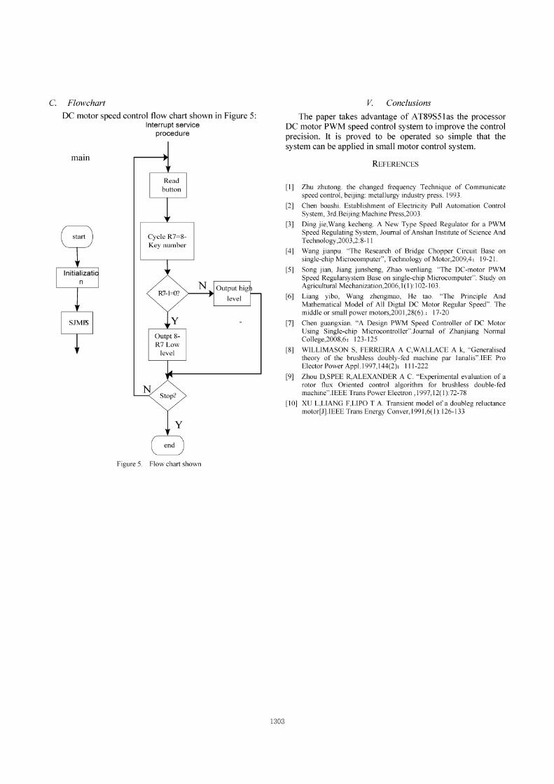
C. Flowchart
DC motor speed control flow chart shown in Figure 5:Interrupt service
procedure
main
Cycle R7=8-Key number
y
Outpt 8-R7Low
level
NStop?
Figure 5. Flow chart shown
1303
V Conclusions
The paper takes advantage of AT89S51as the processorDC motor PWM speed control system to improve the controlprecision. It is proved to be operated so simple that thesystem can be applied in small motor control system.
REFERENCES
[1] Zhu zhutong. the changed frequency Technique of Communicatespeed control, beijing: metallurgy industry press. 1993.
[2] Chen boashi. Establishment of Electricity Pull Automation ControlSystem, 3rd.Beijing:Machine Press,2003.
[3] Ding jie,Wang kecheng. A New Type Speed Regulator for a PWMSpeed Regulating System, Journal of Anshan Institute of Science AndTechnology,2003,2:8-11
[4] Wang jianpu. "The Research of Bridge Chopper Circuit Base onsingle-chip Microcomputer", Technology ofMotor,2009,4: 19-21.
[5] Song jian, Jiang junsheng, Zhao wenliang. "The DC-motor PWMSpeed Regularsystem Base on single-chip Microcomputer". Study onAgricultural Mechanization,2006,1(1):102-103.
[6] Liang yibo, Wang zhengmao, He tao. "The Principle AndMathematical Model of All Digtal DC Motor Regular Speed". Themiddle or small power motors,2001,28(6).: 17-20
[7] Chen guangxian. "A Design PWM Speed Controller of DC MotorUsing Single-chip Microcontroller".Journal of Zhanjiang NormalCollege,2008,6: 123-125
[8] WILLIMASON S, FERREIRA A C,WALLACE A k, "Generalisedtheory of the brushless doubly-fed machine par lanalis".IEE ProElector Power Appl.I997,144(2): 111-222
[9] Zhou D,SPEE R,ALEXANDER A C. "Experimental evaluation of arotor flux Oriented control algorithm for brushless double-fedmachine".IEEE Trans Power Electron ,1997,12(1):72-78
[10] XU L,LIANG F,LIPO T A. Transient model of a doubleg reluctancemotor[J].IEEE Trans Energy Conver,1991,6(1): 126-133