PW Inscreed Installation - ProWarm™ · All wiring must conform to lEE 17th Edition Part P...
12
INSTALLATION MANUAL Ultra thin cable Easy to install Fully compliant to latest regulations CE approved Suitable for most floor coverings (always check with floor manufacturer) LIFETIME LIFETIME WARRANTY INSTALLATION MANUAL
Transcript of PW Inscreed Installation - ProWarm™ · All wiring must conform to lEE 17th Edition Part P...

INSTALLATION MANUAL
Ultra thin cable
Easy to install
Fully compliant tolatest regulations
CE approved
Suitable formost fl oor coverings
(always check with fl oor manufacturer)
LIFETIMELIFETIMEWARRANTY
INST
ALL
ATIO
N M
AN
UA
L

2support 0843 770 4597
Thank you for investing in our industryleading ProWarm™ underfl oor heating system
This instruction manual contains important information regarding the safe installation and operation
of your heating cable/s.
These installation instructions are not intended to replace or supersede the installation instructions
provided by the manufacturers of your fl oor coverings but to supplement them.
Both sets of installation instructions should be complied with, (always check with the fl oor
manufacturer if you are in any doubt that our heating cable/s are suitable).
Our cable kits are extremely strong but care must be taken when installing them, please follow the
step by step installation guide to ensure a carefree installation.
leading ProWarm™ underfloor heating systemThank you for investing in our industry
LIFETIMELIFETIMEWARRANTY

3www.prowarm.com
Before you begin installing 4
Installation Notes 4
Professional Electrical Installation 4-5
Testing 5-6
Installation instructions 7-10
Do’s & Don’ts 10
Floor types 11-13
CONTENTS
CE approved systemsOur heating cables are CE approved, certifi ed and manufactured to the highest standards using state of the art Tefl on coated cables. All our cables are designed to be 17th Edition Part P compliant and the instructions we supply with them include as much information as possible to ensure that all installations comply with them (please contact us if you are in any doubt).
CE ur hsingart s po an
COuusPaasin
GUA R A NTEE
CABLECABLESAFE
BBLLAABBBBGUUUAAAAA RRR AAA NNNTTTEE
EEE
GGGUU
EEEEEE
CCCCAABBLLLLEAAASSSSSAAAAAFFFFFEEEEEESSSSSAAFFEEEEEEEEEE

4support 0843 770 4597
Always check with the fl oor covering manufacturer for suitability of use with electric Underfl oor heating systems, also check the suitability of any adhesives/latex compounds that are intended to be used with both the fl oor coverings and the heating system.
Before you begin Installing: Please read through these instructions
carefully and check that you have all the components required.
Befo
re y
ou b
egin
inst
allin
g / I
nsta
llatio
n No
tes
Installation Notes■ The system requires a mains voltage 230/240v and must be connected by a suitably qualifi ed person.
All wiring must conform to lEE 17th Edition Part P regulations.
■ Our ProWarm™ inscreed heating cable/s are 17w per linear metre, total wattage per metre squared is determined by the spacing of the cable. (DO NOT place the cables any closer than 50mm at any point).
■ The fi rst part of the cable is the cold tail (coloured black), this carries an earth screen which is either a solid green/yellow earth cable or a silver coloured braid which is connected to the main incoming earth from the supply. The heating cable contains a built in return meaning that the cable only has to be connected to the thermostat from one end, this cable is double insulated with a self regulating heating element.
■ For larger areas, if two or more cables are supplied, these can usually be connected together by using a small blank fronted connection box and a single cable connected to the thermostat.
■ The electrical and electromagnetic fi elds generated are negligible and well within all recommended European and International guidelines.
■ The heater cable MUST NOT be cut or cross at any point.
■ Any (load amperage) 16 amps or over must be connected via a contactor fi tted with a snubber across the contactor coil
Contents of Heating Cable Kit
5.5mm twin-core heating cable
High adhesion fi xing tape
Digital thermostat & separate fl oor sensor
Guarantee Certifi cate
Conduit for fl oor sensor
Double sided tape
Spray adhesive
Professional Electrical Installation
The installation of electrical systems presents risks of fi re and electrical shock which can result in personal injury.
Caution should always be taken to guard against each such risk. Only a qualifi ed electrician should connect the
heating cable/s to the thermostat and / or to the electrical supply circuit.
Carry out all electrical work required to install ie. chase walls and install back boxes for fused spurs and
thermostat position. Please make sure all works conform to the current regulations.

5www.prowarm.com
Prof
essi
onal
Ele
ctric
al In
stal
latio
n / T
estin
g
Caution:Due to the new requirements of the Part P Regulations, only a qualifi ed person who is familiar with the construction and operation of the apparatus and the hazards involved shall make the fi nal connections to the electricity supply and test the installation.
ProWarm™ Underfl oor Heating Systems
Must be controlled via an rcd protected circuit, for systems not exceeding 13 amps a fused spur that has contact
separation in all poles that provides full disconnection under Cat 3 conditions can be used, for systems larger
than 13 amps a suitable protective device that complies with regulations must be used (please contact us for
technical assistance or consult a fully qualifi ed approved electrician). If you are in any doubt about the electrical
installation then please contact our technical advice centre.
All such connections MUST be in accordance with BS7671 17th Edition Part P wiring regulations.
Note: When installing thermostats in bathrooms they should always be located
outside the room and use the fl oor probe supplied, always check with a qualifi ed
electrician that all electrics are in safe and suitable zones.
IMPORTANT
Testing
Each and every ProWarm™ cable is carefully tested
before it is shipped from the factory and is packed
suitably to avoid damage during transit. However,
damage does sometime occur in storage or transit, and
sometimes during installation. We strongly recommend
you test your cable/s:
■ After unpacking them but before you install them.
■ After you have installed them but before you install the fl oor screed (i.e. while the cable is still exposed).
■ After installation of the fl oor screed but before the thermostat or contactor is connected.

6support 0843 770 4597
Test
ing
At this point and insullation resistance test must be carried out.
Please see table for the values you should see when testing the cable.
IMPORTANT
Twin Conductor 17w/m/230 VAC
Code Length Watts Resistance (M) (W) (Ohms)
FHC-T-17W/170 10 170 311.2
FHC-T-17W/250 15 250 211.6
FHC-T-17W/360 21 360 146.9
FHC-T-17W/460 27 460 115.0
FHC-T-17W/600 35 600 88.17
FHC-T-17W/700 41 700 75.6
FHC-T-17W/920 54 920 57.5
FHC-T-17W/1100 65 1100 48.1
FHC-T-17W/1340 79 1340 39.5
FHC-T-17W/1430 84 1430 37.0
FHC-T-17W/1630 96 1630 33.3
FHC-T-17W/1900 112 1900 27.8
FHC-T-17W/2400 141 2400 20.0
FHC-T-17W/2890 170 2890 18.3
FHC-T-17W/3100 183 3100 17.06
Single Conductor 17w/m/230 VAC
Code Length Watts Resistance (M) (W) (Ohms)
FHC-S-17W/170 10 170 311.2
FHC-S-17W/250 15 250 211.6
FHC-S-17W/360 21 360 146.9
FHC-S-17W/460 27 460 115.0
FHC-S-17W/600 35 600 88.17
FHC-S-17W/700 41 700 75.6
FHC-S-17W/920 54 920 57.5
FHC-S-17W/1100 65 1100 48.1
FHC-S-17W/1340 79 1340 39.5
FHC-S-17W/1430 84 1430 37.0
FHC-S-17W/1630 96 1630 33.3
FHC-S-17W/1900 112 1900 27.8
FHC-S-17W/2400 141 2400 20.0
FHC-S-17W/2890 170 2890 18.3
FHC-S-17W/3100 183 3100 17.06
Resistance Values
A simple test is a visual inspection to make sure there is no visible damage to the heater, and in particular to
the cable component in the heater. A simple electrical inspection can be done with an ohm meter to make sure
the ohm resistance is what it should be (see page 8). Ohms resistance can vary signifi cantly depending on the
ambient temperature and an allowance of - 10% to + 10% from the nominal value is acceptable. At this point an
insulation resistance test should now be carried out.
Metal fi xing bands of 25m are available if required

7www.prowarm.com
Inst
alla
tion
inst
ruct
ions
STE
P 1
/ 2
STEP 1Calculate the cable spacing.
This is a very important step and
MUST be done correctly to ensure all
the cable is used up and avoid extra
work later.
First measure the area to be heated in sqm (do not include the area taken up by fi xed objects such as baths/showers and kitchen units), then divide this area by the length of the cable shown on the drum. The cable is 170 watts per linear metre so a 1350 watt kit contains 79 metres of heating cable. The spacing is calculated by dividing the total sqm of the area to be heated by the cable length in metres (see example below).
Example room: 2x3m (6m2) less 0.9 for shower tray = 5.1m2. A 65m inscreed cable kit would be suitable (5.5mm).
Cable spacing is calculated at 5.1 (room size) divided by 65 (cable length) = 0.084m (8.4cms) leaving a gap of approx 4cms from edge of the room.
IMPORTANT
STEP 6Once the spacing has been determined,
leaving a perimetre of 5-10cms around
the edge of the room mark out the fl oor
at the calculated intervals. This will
usually be between 5 and 10cms.
If your calculated spacing is less than
5cms STOP and do not install. The kit
size is too big for the room.

8support 0843 770 4597
Inst
alla
tion
inst
ruct
ions
STE
P 3
/ 4 /
5
The heater cable MUST NOT be cut or
cross at any point (the heater cable/s
should not be spaced closer than 50mm
at any point to each other).
Adjust the spacing if necessary to
ensure all the cable is used up and the
fl oor has an even covering.
STEP 3
NOTE: thermostat shown for illustration is to be sited outside the bathroom, please consult qualifi ed electrician if in any doubt of zoning regulations.
Check the cable resistance and
insulation resistance values after
laying. Check if these values are
consistent with pre-install values.
Record values on the guarantee
certifi cate which came with the kit.
STEP 4
Position the sensor in the black conduit supplied between two runs of cable and fi x into
position. The sensor wire can be shortened or lengthened. If you need to cut the sensor wire
you must only cut the end containing the wires. DO NOT cut the end which contains the plastic
sensor. The connections to the thermostat can now be made.
The earth from the cable can then be connected to the earth from the incoming supply by
using the earth terminal in the back box. If using a plastic box with no terminal then a suitable
terminal block can be used. (At this point an insulation resistance test must be carried out by
a qualifi ed electrician). The rest of the thermostat connections can be made according to the
separate instructions provided.
STEP 5
9www.prowarm.com
Inst
alla
tion
inst
ruct
ions
STE
P 6
/ 7
STEP 6Run the power leads from the start of
the cable up to the thermostat position.
If the cable contains a silver earth braid
around the cold tail this can be unbraided
by using a screwdriver and pulling down the braid
to separate the strands these can then be twisted
into a single strand, this is then connected to the
main earth supply - if the cold tail contains a solid
green/yellow earth then this can connected straight
to the main earth supply. If using multiple cables
route all power leads through a conduit from the
fl oor to a junction box and supply the junction box
from the thermostat. The earth from the cable can
then be connected to the earth terminal in the back
box, (shown here) if using a plastic box with no
terminal then a terminal block can be used.
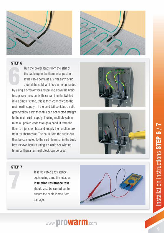
STEP 7Test the cable’s resistance
again using a multi-meter, an
insulation resistance test
should also be carried out to
ensure the cable is free from
damage.

10support 0843 770 4597
Inst
alla
tion
inst
ruct
ions
STE
P 8
/ Do’
s &
Don
’ts
STEP 8Install screed in line with illustrations as shown on page 11. Allow screed to dry without turning on the heating. NOTE the heating may be slow to react at fi rst, especially if installed on a new screed fl oor or in a new building. Start by setting the fl oor temperature at approx 18°C - and build up by 1°C per day until your desired temperature is reached.
Please see separate instructions for connection and operation of digital thermostat.NB: A 65mm screed can take up to 100 days to dry unless an accelerator has been added. Consult screeding company to clarify drying times.
Do read through these instructions carefully before beginning work.
Do use fl exible adhesives and grouts.
Do test the cable before screeding.
Do be careful not to damage or dislodge the cable during screeding.
Do ensure the cable is spaced no closer than 50mm between loops.
Do try to protect the cable during screeding.
Do wait for the recommended screed drying / curing time before turning on the system.
Do read the separate installation and operating instructions for the thermostat.
Do ensure the joint between the cold tails and heating cable is beneath the tiles.
Don’t attempt to cut the heating cable at any point.
Don’t allow the wires to cross or touch.
Don’t allow excessive foot traffi c over the wire before screeding.
Don’t cut tiles over the heating cable.
Don’t place tools or materials on topof cable.
Don’t place any product over the fl oor covering that has a higher tog valuethan 2.5.
Don’t place any bean bags or fi xed furniture over the fl oor covering.
Don’t place cable closer than 100mm near any pipes.
Don’t turn on the heating inscreed cable while it is rolled up or still on the drum.
Do’s and Dont’s for Installation
Please ensure that the cold tail joint (the join between the heating cable and fl exible supply lead) is fully encapsulated in adhesive or levelling compound underneath the fl oor covering
Please ensure that the end joint (the join at the end of the cable which is black) is also fully encapsulated in tile adhesive or levelling compound
Both the cold tail joint and end joint MUST NOT be placed into a cut out of insulation or subfl oor and just covered with tape, this can cause the cable to overheat and eventually fail!
DO NOT BEND THE COLD TAIL JOINT AT ANY POINT
IMPORTANT

11www.prowarm.comprowarm
Floo
r ty
pes
1. Floor Covering
2. Screed 65mm
3. Inscreed Cable
4. Concrete Pad(less than 100mm)
5. Insulation 50mm
6. Subfl oor 100mm
1. Floor Covering
2. Screed 30mm
3. Inscreed Cable
4. Screed 35mm
5. Insulation 50mm
6. Concrete Pad
1. Floor Covering
2. Screed 65mm
3. Inscreed Cable
4. Insulation Board 10mm
5. Concrete Pad
IF CONCRETE PAD IS LESS THAN OR EQUAL TO 100mm & INSULATED:You may install the heating cable directly on top of the concrete pad.
IF CONCRETE PAD IS MORE THAN 100mm OR UNINSULATED:You must install insulation before laying the heater.There are two options available
OPTION 1
OPTION 2

Visit us online for a list of suppliers:www.ProWarm.com
Call us direct for technical advice:0843 770 4597
PRODUCT WARRANTYProWarm™ fl oor heating mats & cables come with afull lifetime warranty
CableSafe™ GuaranteeProWarm™ is the only company that offers you a no quibble exchange on a damaged cable!
GUA R A NTEECABLESAFE
GUUUAAAAA RRR AAA NNNTTTEE
GGGUUU EEEEEE
Unit 12, Carnival Park, Carnival Way, Basildon, Essex, SS14 3WN
T: 0843 770 4597www. .com


![Rainbow Heart - artecy.com · 7777777 777777777 7777777777777 ooooooo 77777 7777777 7777777777777 oooooo]]]]] ddd ddd ddd ddd ddd ™™™™™™™™™™™ ™™™™™™™™™™™™™™™™™](https://static.fdocuments.us/doc/165x107/5f4a4ec8ec2fea16bc048a6a/rainbow-heart-7777777-777777777-7777777777777-ooooooo-77777-7777777-7777777777777.jpg)