[PVUZ Structural Silicone Glazing Manualfiles.autospec.com/za/fg-trading/FGTrading StructuralGlazing...
32
;YLTJV :LHSHU[ :VS\[PVUZ Structural Silicone Glazing Manual
Transcript of [PVUZ Structural Silicone Glazing Manualfiles.autospec.com/za/fg-trading/FGTrading StructuralGlazing...

Structural Silicone Glazing Manual

2
Structural Silicone Glazing
Structural Silicone Glazing
- An Introduction
Types of Structurally Glazed Wall
Systems
Structural Silicone Glazing Criteria
Structural Silicone Glazing Testing
PROCEDURES FOR ONE-PART AND
TWO-PART SILICONE SEALANT
Introduction
Guide for Workmanship
Guide for Sealant Application
A. Cleaning
B. Priming
C. Masking
D. Sealant Application
Guide for Field Adhesion Check
A. The Tab Adhesion Test Method
B. The Hand Pull Adhesion
Test Method
Guide for Reglazing
A. Glass failures
B. Sealant failures
ONE PART SILICONE SEALANT
- TREMCO SPECTREM 2
Quality Assurance Programme
Test #1- Tack-Free Time
Test #2- Through Cure
One Component Quality
Check-Log Book
TWO PART SILICONE SEALANT
- TREMCO PROGLAZE II
Quality Assurance Program
Test #1 - Butterfly Test
Test #2 - Snap Time Test
Test #3 - Colour Check
Test #4 - Adhesion Test
Test #5 - Flow-Rate Test
Test #6 - Shore A Test
Two Component Quality
Check-Log Book
On Ratio Verification Techniques
Recommended methods for
confirming on-ratio dispensing
of Proglaze II
Structural Glazing Project
Initiation Form
Calculations
Appendix A: Conversion
Table - Wind Pressure and Speed
Appendix B: Technical Services
Evaluation Request Form
Appendix C: Sealant Coverage Indicator
Index
Introduction
12
12
12
12
13
13
14
15
16
17
18
18
19
19
20
21
21
22
23
25
26
28
Structural Silicone Glazing is a system of
bonding glass to a building’s structural
framing members utilising a high
strength, high performance silicone
sealant specifically designed and tested
for Structural Glazing applications.
Dynamic wind loads are transferred
from the glass, through the structural
silicone sealant, to the perimeter
structural framing.
Aesthetics/design flexibility
Improved thermal efficiency
Reduces or eliminates water
and air infiltration
Reduces the potential for
thermal breakage of glass
Eliminates water ponding
on slope-glazed applications
Al Salemiya Tower, Dubai, U.A.E.
Inside
Cover
3
4
5
6
8
9
9
9
10
10
10
10
11
Front Cover Photographs (From left to right):
Citibank Plaza,Hong Kong Sanoma Building - Helsinki, Finland
29Product Selection

3
Types of Structurally Glazed Wall Systems
Butt Glazed
Two Sided Four Sided
All Glass SystemsS t 2 / T il 500Spectrem 2 / Tremsil 500(Weather Seal)
m 2SpeS ctremBead)(Weather
0Spectrem 2 / Tremsil 500(Weather Seal)(We( ather Seal)
Spectrem 2(Tensile Bead)
CCNC Spongewith Dart
Setting Block
CCompatttttttttttiibbbbbbbibbbiblii eWWedge Gaskett
CCN Spongewith Dart
Setting Block
CCompatibleWWedge Gaskettettttttttttttttt
Silicone CompatibleSilicone CompatibleBack-up Spacer
ctrem 2Specp Bead)(Cap
ctrem 2Spep Bead)(Cap
Utilises glass vision lites with glass mullionsto provide a total see-through wall.
A Structurally Glazed System which isconventionally glazed at opposite sides bututilises Structural Silicone to bond glass to theperimeter framing on the remaining two sides.
A Structurally Glazed System that utilisesStructural Silicone to bond glass to theperimeter framing on all sides.
A system where lites are conventionally glazedat the head and sill and the vertical “Butt”joint is unretained.
Spectrem 2Specttrem 2(Tensi d)ile Bead
SiliconeeeneSiliconC patibleCompaSett g ocSetting Block
Proglaze IIProglaze(T Bead)(Tensile Be
Tremco Structural Glazing TapegSilicone Compatible
Specctrem 2 /Tremmssil 500(Weaather Seal)

4
Criteria and Testing
Structural glazingperformance factors
Design Windload (PSF)
Glass Size
Performance Criteria
Framing Design
Tensile Bead Sizing
Substrate Finishes
Structural Silicone Sealant Selection
Substrate Preparation
System Compatibility
Design windload
As specified by project specifications
NOTE: High-load areas such asbuilding corners and upper elevations.
Glass size
Identify largest short lite dimension
for each windload area to properly
calculate Tensile Bead Surface
Contact Depth
Performance criteria
Safety factor as required by governing
code body and specification
Laboratory and Field Tests
Design parameters
Framing design
Vertical or Sloped?
Low, Mid or High-rise?
Butt, Two or Four-sided?
Shop or Field Glazed?
Substrate finishes
Alodine
Paint
- Fluorocarbons
- Siliconised Polyesters
- Siliconised Acrylics
Anodic
Mill finished aluminium is not an
acceptable substrate for structural
silicone glazing applications.
Structural sealant selection
Single or Plural Component?
Medium or High Modulus?
Colour Requirements?
System Compatibility?
Substrate preparation
Cleaning
Priming Requirements
Structural Silicone Glazing Criteria
Comparison of Bead Design
Single BeadSingle Bead Dual BeadDual Bead L Shaped Bead“L” Shaped Bead

5
System compatibility
Glazing Components
Glass
Framing System
Utilise ASTM C-1087 and sealant
manufacturers proprietary test
methods to establish compatibility
Compatibility
Colour change of the structural silicone
sealant as a result of exposure to a
glazing component.
Adhesion of the structural silicone
sealant to the glass test substrate
and the glazing accessories.
Change in the strength of the structural
silicone sealant as a result of exposure
to a glazing component.
Structural silicone spacers,blocks and gaskets
TYPE I:
Specified where adhesion of the sealant
to the accessory is not required.
TYPE II:
Specified where adhesion of the
sealant to the accessory is desired.
Structural silicone sealantmanufacturing services
A. Shop Drawing Review
B. Specification Review
C. Adhesion Testing
D. Compatibility Testing
E. Start-Up
F. Site Inspections
A. Shop Drawing Review
Verification of sealant contact depth
Proper use of glazing materials
Confirmation of glass type and size
Confirmation of metal finish
Sealant selection
B. Specification Review
Design windloads
Testing requirements
- ASTM C-794
- Heitmann testing
- Others
Performance requirements
C. Adhesion Testing
All substrates
Solvent recommendation
Priming requirements
D. Compatibility Testing
All glazing components
ASTM C-1087
Proprietary test methods
Structural Silicone Glazing Testing
AAM Tower, Dubai, U.A.E.
6
Structural Glazing Procedures
Tremco illbruck, as a recognized
supplier of structural silicone sealant
and compatible glazing materials,
understands the high performance
requirements and potential liabilities
inherent to structurally glazed walls.
For these reasons, Tremco illbruck
offers a multitude of preconstruction
project reviews and testing programs
to ensure product performance
characteristics and glazing integrity.
This program, founded in industry
practice and specifications, is offered
to our client at no additional charge
and demonstrates Tremco illbruck’s
commitment to quality and attainment
of the highest standards.
Each structurally glazed project in
which Tremco illbruck is involved is
reviewed and tested in accordance with
the parameters of this in-house program.
Pertinent recommendations and results
are shared with the customer with the
assistance of Tremco illbruck Sales and
Technical Services Representatives.
Each member of this team has a keen
sense of commitment to the success
of each project.
The following description is an overview
of the minimum information required by
Tremco illbruck prior to the beginning
of each structural glazing project. This
information is gathered by completing
the ’Structural Glazing Project Initiation
Form’. It is part of the ‘Tremco illbruck
Structural Glazing Procedures’
programme to be followed by
each contractor for each project.
A. General information on theproject such as:
1. Project title, size and location
2. Architect and Consultant involved
in the project
3. Fabricator
4. Glazing and caulking subcontractors
5. Glazing start and completion date
B. Review of the structuralglazing details to identify:
1. Proper use of Tremco glazing
materials including sealant, gaskets
and setting blocks.
2. Proper tensile bead location.
Structural beads are normally
located on the interior face of the
lite or panel (#2 or #4 surface) with
bonding to a structurally sound
substrate such as a horizontal
or vertical aluminium mullion with
a specified architectural finish.
3. Confirmation of glass types
(reflective, opacifier, etc.) and
supplier, identification and description
of coatings, type of glass (Monolithic,
I.G. unit, laminated, etc.) with their
respective sizes.
4. Confirmation of coating/anodizing
company, identification of coating
(type, name, code and batch number)
and location of metal and substrate
finishes. Mill finished substrates are
typically not acceptable for structural
glazing applications.
5. Verification of proper sealant
selection and usage.
We Are Your Partners In Performance
Introduction
Complete analysis of requirements
Analytical inspections and
classifications of problem areas
Assistance in preparation of written
specifications, tailored to the needs
and requirements of your project
Pre-installation inspection
On-site contractor instruction
Periodic inspection of work in progress
to ensure compliance to specifications
Ongoing post application inspections
of the completed installations
Your Tremco illbruck Representative
provides total co-ordination from the
drawing board through job completion
on new work and remedial projects.
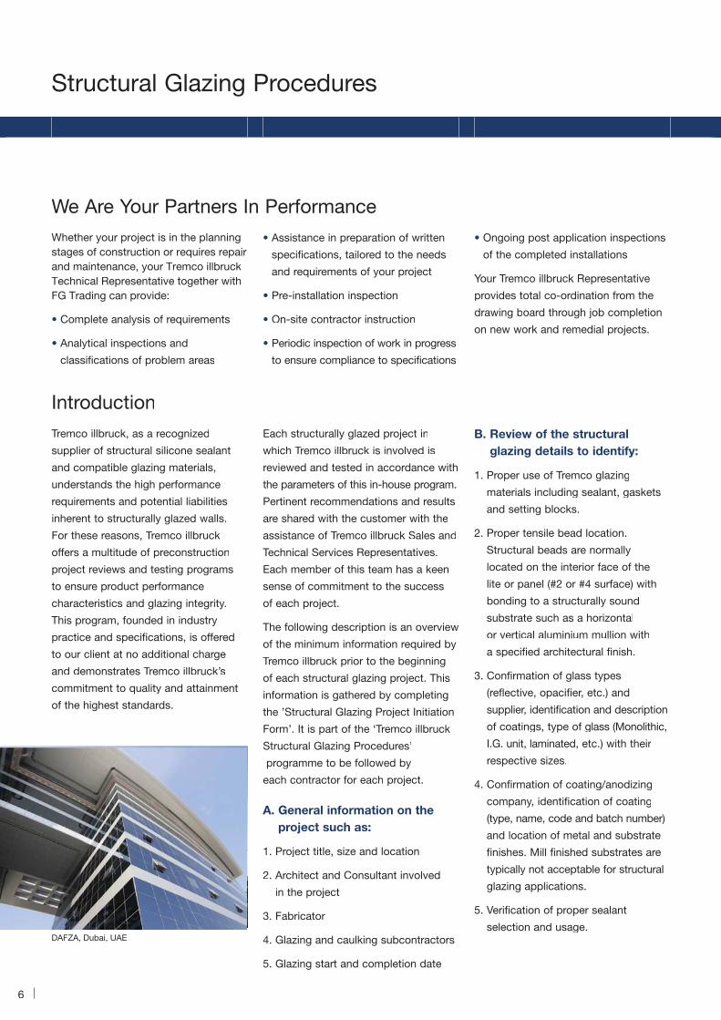
DAFZA, Dubai, UAE
Whether your project is in the planningstages of construction or requires repairand maintenance, your Tremco illbruckTechnical Representative together with FG Trading can provide:

7
C. Project specification reviewto identify:
1. Specific wind load requirement for
the project (positive and negative
wind load).
2. Proper tensile bead sizing: the
sealant bite or sealant contact depth
(SCD) is calculated from the design
wind load and glass dimensions.
Based on these calculations Tremco
illbruck recommends a minimum
tensile bead sIze of 6 mm x 6 mm.
Tensile beads (sealant bite) exceeding
19 mm warrant special consideration
as sealant curing characteristics may
be affected. Please consult your
Tremco illbruck Sales Representative
for special guidelines.
3. Identify the type of structural
glazing application (2 sided, sloped),
on site or in plant application,
vision and/or spandrel application.
Spectrem 2 is recommended for
2 sided structural only.
4. Testing designated and required
beyond that typically done.
5. Information and/or performance
requirements specific to a project.
D. Substrate requirement foradhesion testing:
This is to determine proper cleaning
techniques and determine priming
requirements. Substrates typically tested
include aluminum framing and glass or
other glazing panels. Substrates should
be submitted to Tremco illbruck
Technical Services Department and be
representative of those to be used on the
actual project (production run sample).
Tremco illbruck requests a minimum of
1239 square cm of substrate for each
sealant to be tested. The surface where
the adhesion test will be performed
must be clearly indicated!
Adhesion testing is performed as per
Tremco illbruck/ASTM Test Method.
Result on adhesion for Spectrem 2 will
be available after 28 days upon receipt
of the substrate at Tremco illbruck
Technical Services laboratory.
E. Identification of substratein contact with the siliconestructural glazing sealant:
We want to verify that all the elements
installed within the glazing pocket are
compatible when in contact with the
silicone sealant (tensile bead) and will
not affect its in-place performance.
If required, compatibility testing can
be run according to Tremco illbruck
Modified ASTM C-1087.
The test will determine colour change
or adhesion loss as a result of sealant
contact or proximity of incompatible
materials. Substrates to be tested
include, but may not be limited to:
setting blocks, structural spacer
(tapes or gaskets), compression
gaskets, insulating glass edge seals,
glass laminates, backer rod, weather
seal, thermal break, etc.
F. Other tests as required by theproject specifications or asrequested by consultants,engineers and contractors.
Upon completion of the drawing and
specification review, adhesion and
compatibility testing, a formal report is
issued which detail recommendations
and test results specific to the success
of the individual project. These results
and recommendations are intended to
serve as a base of information which
should be confirmed on actual project
applications at ongoing intervals as
described in the following structural
glazing procedures. This ensures
consistent performance quality and
confirms laboratory results.Emirates Towers HotelSheikh Zayed Road, Dubai, U.A.E.

8
A. All components (aluminum and
glass) receiving the structural glazing
silicone sealant shall be thoroughly
wiped with a clean cloth dampened
with a recommended cleaner, as
approved by Tremco illbruck and
immediately followed by a dry wipe
(2 rag method). Use a clean cloth for
the dry wipe. Special precautions
must be taken in cold weather to
ensure the surfaces are free from
frost and/or condensation.
B. All surfaces once cleaned or primed
should be handled carefully so as
not to contaminate the surfaces.
C. All framing shall be checked prior
to glazing to make certain that the
opening is square, plumb, and
secure in order that uniform sealant
bite, face and edge clearances are
maintained. Inspect all butt and
mitre joints. If these joints are open,
they shall be sealed prior to glazing
with identical sealant. Maintain
minimum edge clearances between
glass and sash, as outlined by the
glass manufacturer, and sealant
contact depth (sealant bite) as
recommended by Tremco illbruck
for this specific project.
D. Setting blocks shall be used to
support the glass/I.G. unit in structural
glazing applications. The use of
setting blocks will prevent the addition
of stress applied on the structural
tensile bead due to the dead load
of the glass/I.G.unit.
E. Locate setting blocks on the sill
member as recommended by the
glass manufacturer. Setting blocks
shall be recessed in 2-sided structural
application glazing (with mechanical
jamb retention) to allow for adequate
sealant contact (weather seal) and
glass support. When using insulating
glass in a structural glazing
application, the industry has generally
accepted setting blocks recessed
50% of the thickness of the outboard
lite of glass. The I.G. unit supplier in
conjunction with the sealant supplier
shall confirm the type of setting blocks
that are compatible and can be used
in the structural glazing application.
F. Structural spacers used in this
application must be compatible with
the structural silicone sealant and
positioned on the frame to ensure
correct sealant contact depth as
recommended and specified by
Tremco illbruck. The silicone
compatible spacers shall be of
required hardness to maintain
a recommended uniform face
clearance for all glass sizes.
G. The sealant cavity created by the
installation of the structural spacer
should be located parallel to the
nozzle of the gun or cartridge
allowing direct entry of the sealant
into the cavity. Non-paralleled or
indirect access of the sealant to the
cavity must be performed carefully
(such as an “L” bead)
H. A full -sized detail of the structural
glazing pocket showing the metal
systems must be submitted for
approval prior to the beginning of
the project. Placement of materials
must be shown on the details.
If framing from the fabricator differs
from the submitted details, the
principal parties must resolve
differences before proceeding
further with the project.
I. All materials shall be used in
accordance with Tremco illbruck’s
printed instructions. A meeting to
review procedures, tests required
and sealant application should be
held during bid stage and prior to the
beginning of the work on the project.
J. When using Spectrem 2 silicone
sealant in a 2 sided structural glazing
application, temporary retainers will be
required (field glazed only) to maintain
the position of the glass, in plane,
until the structural glazing sealant
has reached its full cure (after 14 to
21 days), at which time the retainers
can be removed and the resultant
voids in the weather seal filled.
K. Adhesion test must be performed
by the contractor at the beginning
and during the project application.
A logbook recording all tests
verifications must be kept by the
contractor as it will be used for his
own control (refer to one and two
part silicone sealant - Quality
Assurance Program).
Structural Glazing Procedures
Guide for Workmanship

9
It is essential that Tremco Structural
Glazing Sealant is installed in accordance
with Tremco illbruck’s recommendations
and specific written instructions.
Proper surface preparation is extremely
important to the longevity and
performance of Tremco Structural
Silicone Sealant. Samples (substrates)
tested must be production run samples
and be representative of the materials
to be used on the job site.
A. Cleaning
1. Methyl Ethyl Ketone (MEK) or
Isopropyl Alcohol (IPA) are the most
commonly recommended solvents
for cleaning metal and glass intended
for structural glazing applications.
2. The purpose of these solvents is to
act as a “degreaser” to remove the
cutting oils and other contaminates
used in the fabrication of the framing
system. Selected solvents must be
clean, fresh as approved by Tremco
illbruck Technical Services and must
comply with local occupational safety
codes. When being used indoors,
such as a factory environment, proper
ventilation must be provided.
3. Pour the approved solvent onto a
clean cloth. Do not place cleaning
cloth into the solvent solution
container. This avoids solvent
contamination, which can lead to
sealant adhesion problem. Vigorously
rub the glass and metal surfaces
to remove the contaminates.
Continuously rotate the cloth lifting
off the oils loosened by the solvent.
4. Cloths used for cleaning of all framing
members should be white lint-free
and resistant to the recommended
cleaner. Change the cloths frequently
as they become soiled during the
cleaning operation. White rags show
soiling easily.
5. Do not allow the solvent to air dry
during the cleaning procedure. After
the solvent wipe, follow immediately
with another clean cloth to wipe the
surface dry (2 rag method). Allowing
the solvent to dry on the surface
without wiping with a second cloth
negates the entire cleaning procedure,
because the contaminants are
redeposited as the solvent dries.
6. When cleaning deep, narrow joints,
wrap the cleaning cloth around a
clean, narrow-blade putty knife.
This permits force to be applied
to the surface to be cleaned.
7. Clean only as much area as can
be sealed in one (1) hour. If cleaned
areas are exposed to rain or
contaminants (dirt, dust, etc.),
the surface must be cleaned again.
8. Keep solvent containers closed when
not in use. Temperature and humidity
will affect the evaporation rate of the
applied solvent therefore affecting
its cleaning power.
9. Caution:
a. Never use a paintbrush for the
cleaning procedure. It is not effective
in removing the contaminates off the
surface. The rubbing action of the
cloth is critical and essential for
loosening up the contaminates
from the substrate.
9. b. Some “cutting oils” used in the
fabrication process may not be soluble
in MEK or IPA. This should be verified
before commencing the project.
B. Priming
1. Primer when properly used, will help
assure a strong and consistent
adhesion of the silicone sealant to
the substrates to which it may be
difficult to bond. If a primer is
required, it will be confirmed during
the adhesion test executed prior
the beginning of the work.
2. Tremco offers Primer N°10 for most
metal finishes. Primer N°10 is a
non-film forming primer, which is
moisture sensitive. This sensitivity
to water or humidity manifests itself
by turning cloudy or developing
white precipitates in the fluid within
the container. Should either of these
conditions exist, the primer should
be discarded. Tremco Primer N°10 is
only supplied in one-pint containers.
3. Always pour Primer N°10 onto a
clean applicator. Never place the
applicator into the primer container.
4. Apply a thin film of Primer N°10
using a clean cloth. Excessive
application may result in a white
powdery deposit, which must be
removed before sealant application.
This white deposit can be removed
with a clean cloth dampened with
the recommended cleaner. Reapply
the primer once the substrate is dry.
Guide for Sealant Application

10
Structural Glazing Procedures
2. The surfaces to which the silicone
sealant adheres should be designed
smooth: free of nibs, serration,
grooves and alike, so as not to
impede the flow or adhesion of the
silicone sealant to the substrates on
its entire surface contact depth.
3. Compatible structural spacers shall
be installed to keep the glass properly
spaced as per the approved drawings.
Refer to the approved structural
glazing detail for the configuration of
sealant and the placement of spacer.
Face clearance created by the
structural spacer should be a
minimum of 6 mm wide to
accommodate penetration of the
sealant to the full depth of the cavity.
4. Prime surfaces as required by
Tremco illbruck, taking care to
protect the surfaces that do not
require primer. If primer is installed
accidentally on surfaces other than
the one specified, it should be
removed immediately with the help
of a clean cloth dampened with the
recommended cleaner.
5. When gunning the silicone sealant
into the cavity created by the
structural spacer between the glass
and the metal, a back pressure
should be created such that the
silicone sealant swells up behind
the nozzle tip above the sight line,
ensuring full depth penetration of the
sealant. Air pockets or voids along
the edges are not acceptable and
should be reported to the job
foreman for immediate repairs.
6. All sealant beads must be tooled
immediately after application, forcing
the sealant into contact with the
sides of the joint. It will assure a full
and continuous contact of the
sealant with both substrates and
reduce/eliminate the risk of air
entrapment within the tensile bead.
Avoid “pulling” the sealant out of the
joint by frequent cleaning of the
tooling instrument. Dry tooling is the
recommended tooling method.
Do not tool with soap or detergent
solutions. Tooling time for Spectrem 2
is equal to the skin time value as
published in the data sheet.
7. All non-specified surfaces having
received silicone sealant should be
cleaned off before it cures. This is
best accomplished with an MEK or
IPA soaked cloth. Failure to do so as
soon as possible can lead to very
costly removal methods later on.
8. Follow Tremco illbruck’s
recommendations for curing periods
and transport time for factory or
field sealant applications. These
recommendations can vary from
job-to-job.
9. Use structural silicone sealant, which
is within its stated shelf life. Verify
the batch number of the silicone
sealant for expiry date upon its
arrival. Store in a dry environment at
a temperature between 15 - 27°C.
Notes: All cleaners or primers to be
used on the structural glazing
application should be poured from the
main container into small containers
and poured from this vessel on to the
cleaning cloth to prevent contamination
of dirt into the container. Should the
cleaner or primer become contaminated
with dirt, discard without hesitation.
Pour off only sufficient cleaner or
primer that will be used at one time.
Users of solvents or primers should
follow the manufacturer safety
recommendations.
5. Caution: Primers are not to be
substituted for good surface
preparation. The substrate to
receive the primer shall be thoroughly
cleaned using the recommended
cleaner and dried prior to the
installation of the primer.
6. Allow the primer to dry for a minimum
of 20 minutes before the sealant
application. Protection of the primed
area from contaminants is essential
to ensure proper adhesion. If the
primed area cannot be kept clean,
the primer is to be removed and the
area re-primed.
6. Do not prime ahead more than can
be glazed per shift. If the primed
area cannot be covered with the
sealant by the end of the day, it
must be removed with a clean cloth
dampened with the recommended
cleaner and the area re-primed.
7. Please refer to the “Primer N°10
Data Sheet” for further information.
C. Masking
1. To provide a neat sight line, masking
tape is commonly used to outline
the joint to be sealed. This reduces
sealant smears, which are often
found aesthetically unacceptable.
2. When masking is required, the tape
must be immediately removed after
the tooling has taken place and
before the cure of the sealant begins.
D. Sealant application
1. The structural silicone sealant
shall be installed as per Tremco
illbruck’s specific job installation
recommendations. All surfaces
must be properly cleaned and/or
primed before sealant application.
11
During the course of the sealant
installation for this project, it is good
practice to verify its adhesion to the
substrate. Two such methods
are available.
A. The “Tab” adhesiontest method
When construction design permits, this
method is performed at the time of the
installation of the sealant. Choose a
location on the framing assembly that
allows accessibility and permits a tab
adhesion/ pull test to be applied at the
same time the unit glazed is found. At
the appropriate cure period (generally
14 to 2l days for Spectrem 2) a pull test
on site could be run to confirm surface
preparation and adhesion of the sealant.
This adhesion/ pull test is performed
as follows:
1. The on-site “tab” sample is to be
applied as per Tremco illbruck’s
recommendation for this specific
project including appropriate
cleaners and primers.
2. After the cure period, take a razor
blade and under-cut one end of the
tab, exposing a “flap” that can be
grasped with fingers.
3. Pull this “flap” at approximately 90°
angle. Cohesive failure of a tab is
the desired result.
This method takes advantage of not
disturbing the original structural sealant
after its installation and subsequent
repairing of the sealant.
B. The “ Hand Pull” adhesiontest method
The most popular method employed
to verify the on-site adhesion on the
installed structural sealant. This test is
generally run after 14-21 days for
one-part silicone sealant such as
Spectrem 2. This hand pull test
procedure is performed as follows:
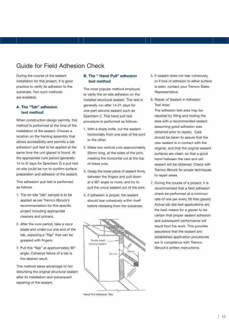
1. With a sharp knife, cut the sealant
horizontally from one side of the joint
to the other.
2. Make two vertical cuts approximately
50mm long, at the sides of the joint,
meeting the horizontal cut at the top
of these cuts.
3. Grasp the loose piece of sealant firmly
between the fingers and pull down
at a 90° angle or more, and try to
pull the uncut sealant out of the joint.
4. If adhesion is proper, the sealant
should tear cohesively within itself
before releasing from the substrate.
5. If sealant does not tear cohesively,
or if loss of adhesion to either surface
is seen, contact your Tremco Sales
Representative.
6. Repair of Sealant in Adhesion
Test Area:
The adhesion test area may be
repaired by filling and tooling the
area with a recommended sealant
(assuming good adhesion was
obtained prior to repair). Care
should be taken to assure that the
new sealant is in contact with the
original, and that the original sealant
surfaces are clean, so that a good
bond between the new and old
sealant wilI be obtained. Check with
Tremco illbruck for proper techniques
to repair areas.
7. During the course of a project, it is
recommended that a field adhesion
check be performed at a minimum
rate of one per every 50 lites glazed.
Actual job site test applications are
the best means for a glazier to be
certain that proper sealant adhesion
and subsequent performance will
result from his work. This provides
assurance that the sealant and
established application procedures
are in compliance with Tremco
illbruck’s written instructions.
Guide for Field Adhesion Check
Hand Pull Adhesion Test
50mm90 min
Tensile beadsilicone sealant

12
Structural Glazing Procedures
The design professional, when designing
structural glazing systems, should
address glass replacement needs
and accessibility.
Glass replacement must allow for proper
glass support, bite, edge clearances
and tensile bead sealant dimensions.
Tremco illbruck Technical Services must
be involved in this investigation and
subsequent replacement/re-glazing
procedures. The re-glazing procedures
will incorporate temporary retainers for
holding the glass in place while the
replacement sealant cures.
There are basically two types of
replacement failures:
1. Glass Failures
2. Sealant Failures
a. Adhesive
b. Cohesive
After a thorough inspection as to cause
of failure, and to the satisfaction of all
parties involved, re-glazing should
commence immediately.
A. Glass failures
For the replacement of glass due to
failures (i.e. broken glass, failed I.G.
unit), proceed as follows:
1. Remove existing glass by cutting the
tensile bead and weather seals. The
sealant adhering to metal (tensile
bead) and glass (weather seal) may
be removed with a utility knife or a
razor blade. A small portion of the
sealant is to remain adhered to the
metal (approximately 1.5mm).
2. Before setting new glass, wipe the
remaining tensile bead with IPA
(Isopropyl Alcohol) or MEK
(Methyl-Ethyl Ketone). Reinstall all
compatible spacers and setting
blocks.
3. Set the glass and install temporary
retainers as required. The opening is
now ready to be resealed.
4. Mask the joint, install the new silicone
sealant, tool then remove the masking.
5. Allow the replacement sealant
to cure as per Tremco illbruck’s
recommendations, then remove
retainers sealing the retainer voids
with the silicone sealant.
NOTE: The replacement silicone sealant
shall be approved by Tremco illbruck
prior to the beginning of the work.
B. Sealant failures
Tremco illbruck shall be notified
regarding all sealant failures in any
structural glazing job. A thorough
review of the total glazing system
is required to determine the
reasons/causes for the failure. Once
Tremco illbruck has investigated the
matter, it will be their responsibility to
establish specific re-glazing procedures.
Some general questions to be
addressed prior to the repairs of the job:
1. What cleaners/ primers are
to be used?
2. How long should the replacement
silicone cure before removing
the retainers?
3. Is there room for attachment
of the temporary retainers?
4. Is the replacement sealant bead
(tensile bead) adequate for load
requirements?
5. Are replacement spacers and setting
blocks compatible?
6. Is the replacement silicone the same
as original?
Resolving these and other questions
as they arise will lead to successful
replacement and continued service.
Guide for Reglazing
Hunt Oil Corporate Headquarters, Dallas, USA
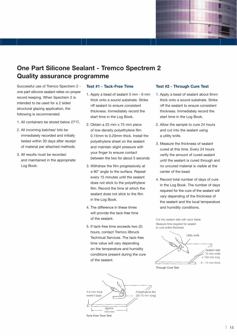
Test #1 - Tack-Free Time
1. Apply a bead of sealant 3 mm - 6 mm
thick onto a sound substrate. Strike
off sealant to ensure consistent
thickness. Immediately record the
start time in the Log Book.
2. Obtain a 25 mm x 75 mm piece
of low-density polyethylene film
0.15mm to 0.20mm thick. Install the
polyethylene sheet on the sealant
and maintain slight pressure with
your finger to ensure contact
between the two for about 5 seconds
3. Withdraw the film progressively at
a 90° angle to the surface. Repeat
every 15 minutes until the sealant
does not stick to the polyethylene
film. Record the time at which the
sealant does not stick to the film
in the Log Book.
4. The difference in these times
will provide the tack-free time
of the sealant.
5. If tack-free time exceeds two (2)
hours, contact Tremco illbruck
Technical Services. The tack-free
time value will vary depending
on the temperature and humidity
conditions present during the cure
of the sealant.
Test #2 - Through Cure Test
1. Apply a bead of sealant about 6mm
thick onto a sound substrate. Strike
off the sealant to ensure consistent
thickness. Immediately record the
start time in the Log Book.
2. Allow the sample to cure 24 hours
and cut into the sealant using
a utility knife.
3. Measure the thickness of sealant
cured at this time. Every 24 hours
verify the amount of cured sealant
until the sealant is cured through and
no uncured material is visible at the
center of the bead.
4. Record total number of days of cure
in the Log Book. The number of days
required for the cure of the sealant will
vary depending of the thickness of
the sealant and the local temperature
and humidity conditions.
13
Successful use of Tremco Spectrem 2 -
one part silicone sealant relies on proper
record keeping. When Spectrem 2 is
intended to be used for a 2 sided
structural glazing application, the
following is recommended:
1. All containers be stored below 27°C.
2. All incoming batches/ lots be
immediately recorded and initially
tested within 30 days after receipt
of material per attached methods.
3. All results must be recorded
and maintained in the appropriate
Log Book.
Tack-Free Time Test
Through Cure Test
One Part Silicone Sealant - Tremco Spectrem 2Quality assurance programme
3-6 mm thicksealant bead
Utility knife
Cut into sealant slab with razor blade
Measure time required for sealantto cure entire thickness
approx100 mm100 mm
ne filmPolyethylenm long)(25-75 mm
slabsSealantwide75 mm w75ongx 150 mm lo
hick6 - 12 mm th

14
Structural Glazing Procedures
One-Component Quality Check - Log Book
Test #1 - Tack-Free Time Test #2 - Through Cure Test
ThicknessSealant
Batch# Start Time End TimeTack-FreeTime (min)
24 HourCure
Days FullCure
OperatorSignature
La Pyramid Du Louvre, Paris, France

15
Today, more than ever, professional
glazers are using plural component
sealant to improve unitized production
and fabrication schemes. The use of
Proglaze II silicone sealant has allowed
many innovative companies to produce
a better product at a more cost effective,
higher level of quality.
The equipment used in delivering Tremco
Proglaze II has three basic functions:
1. Dispensing the sealant components
(base and catalyst) from their
respective containers, through the
metering system and mix elements,
via the gun to the substrate.
2. Effective metering of the base
and catalyst components at the
specified ratio.
3. Thorough mixing of the base and
catalyst components to assure
proper cure and performance
characteristics of the sealant per
the manufacture’s specifications.
It is important to know that the pump
is properly mixing and dispensing both
base and curative. Also, verifying any
inconsistencies in the metal finish
which may adversely effect adhesion
is also important.
Tremco illbruck Engineering Services
recommend the following tests
to be conducted to verify product
performance.
1. At the beginning of each day and/or
every time the pump is started prior
to the installation of the silicone
sealant and intermittently throughout
the day’s production:
a. a butterfly test
b. a snap time test
c. colour check (cure through
to be done afterward)
d. an adhesion test on project
substrate (in-plant adhesion-tab
adhesion)
2. At the beginning, middle and end
of each Proglaze II kit:
a. flow rate of the equipment
b. a shore A test sample
All the test results should be recorded
in the Log Book, indicating the date,
time, and silicone batch number and
cross-referenced to the unit produced
and its location on the building.
It is the ultimate responsibility for the
end-user to maintain proper record
keeping when using Proglaze II. The
equipment suppliers in addition to
Tremco illbruck Engineering Services
are prepared to service this market.
Note:
- Proglaze II is strictly for in-plant use.
- Proglaze II can be used in either
2-sided or 4-sided structural
glazing projects.
- To ensure that the dispensing systems
of meter mixing machinery function
properly, on ratio verification should
be performed to monitor the wear and
tear in the dispensing equipment. The
techniques are enclosed for your
information and reference.
Two Part Silicone Sealant - Tremco Proglaze IIQuality Assurance Programme

16
Structural Glazing Procedures
Test #1 - Butterfly Test
To ensure a proper mix of base and
curing agent, this test will be performed
at each start-up of the dispensing
equipment. The object of the butterfly
test is to verify a homogeneous mix and
detect the presence of any streaking
or unmixed material. It should be done
just before a “snap” sample is taken.
The Butterfly Test is to be performed
as follows:
A. After the pump has been started,
dispense 1.25 litres of mixed base
and curing agent into a container to
flush lines (it should take 2-3
minutes to do so). At the start, the
material will appear predominantly
white because the lines have been
base purged at the previous shut
down.
B. On a sheet of paper, apply a
150 mm to 200 mm long line of
sealant from the gun nozzle.
C. After sealant is applied, fold the
paper in half. Apply ample pressure
to flatten out the bead of sealant.
D. Open the paper towel and lay it flat,
visually inspect the sealant.
E. The sealant must appear uniformly
mixed (the base is white and the
curative is black; the mixed product
is dark charcoal grey). There should
be no white or grey streaks of any
kind in the sealant.
1. If there is no evidence of
streaking and the sealant is a
consistent dark color, a thorough
mix has been achieved. Proceed
with the snap test.
2. DO NOT PROCEED with further
testing and sample preparation if
there is evidence of streaking or an
inconsistent color exists. This
indicates a thorough mix has not
been achieved. Instead, dispense
additional sealant and repeat steps
B through E.
3. If there is still evidence of
streaking or an inconsistent color
exists, some adjustments/repairs
should be done on the dispensing
equipment (static mixer area) until
we achieve a thorough mix.
Butterfly Test Procedure
4321
Bead of Sealant
Paper Unfolded paper not fullyUnfolded paper - not fullymixed sealant (streaks)
p pUnfolded paper -fully mixed sealant
Fold inthe middleof the bead

17
Test #2 - Snap Time Test
Snap Time Test will be performed after
proper mix of base and curing agent
is achieved (refer to Butterfly Test).
This Snap Time Test is performed to
determine the cure rate of the sealant
once mixed and is to performed
as follows:
A. Dispense mixed sealant into a
container (3/4 full). A coffee cup is
suitable for this test. Record time
of sample preparation.
B. Insert any clean stick well into the
sealant in the middle of the container.
C. The “Snap Time” of the mixed
sealant is checked by slowly lifting
the stick straight up from the
container. Initially, the sealant will
form a continuous string from the
stick to the surface of the sealant in
the cup. It should not break when the
stick is lifted approximately 100 -
150 mm above the sealant surface.
D. Wait 20 minutes and repeat step
“C” every 5 minutes.
E. As the material approaches its
designed snap time, the distance
required for the material to break,
when lifting the stick from the
sealant surface, will get smaller
and smaller.
F. Snap time is achieved when lifting
the stick from the material and the
sealant breaks after 12 - 25 mm
distance from the surface of the
sealant in the container. The snapped
sealant will act like a broken rubber
band, i.e. both ends will snap in
opposite directions.
G. Record snap time. The designed
snap time should be between 30
to 40 minutes when done at room
temperature and humidity’ conditions
at the time of testing.
H. Date and time need to be recorded
on the cup, it could be used for
future Shore A testing.
I. Care should be taken to avoid further
mixing or shearing of the sealant
during the snap time testing; this
will affect the snap time result.
J. Snap time result may vary and be
affected by the local temperature,
humidity conditions and the shelf life
of both base and catalyst. As an
example, testing at higher
temperatures reduces snap time
while testing at lower temperature
increases the snap time.
Note: After the mixed sealant has
been tooled in place, it should not
be disturbed once the sealant has
“snapped”; its adhesion to both
substrates may be affected.
If any major discrepancy in the snap
time value is noted, advise Tremco
illbruck immediately.
Snap Time Test Procedure
321
Stick
MixxedSeealant
Sealant hasnot snapped
m100 - 150mm12 - 25mm
Sealant hassnapped

18
Structural Glazing Procedures
Test #3 - Colour Check
At the same time the butterfly test and
snap time are conducted, a sample of
cured sealant should be compared with
the material currently being dispensed.
Colour of a previously cured sample
(control sample) should match that of
the dispensed material. This control
sample is generally produced at the
commencement of the project prior
the installation of the structural
silicone sealant.
If the snap time is in specification and
the butterfly test shows no streaking
and the color check is consistent with
the control, then it is confirmed that the
material is being dispensed, properly
mixed, and should be expected to meet
the performance specifications. At this
point, we can proceed with the
adhesion test.
Test #4 - Adhesion Test
The adhesion test is to be performed
at the start and end of each production
run or day. It will confirm that the
sealant does not change from the
beginning to the end and that you will
have consistent results.
The adhesion test is to be performed
as follow:
A. Clean both finished metal and glass
substrates using the recommended
cleaning procedures.
B. Apply a bead of the silicone
sealant to the substrates in use,
approximately 12 mm wide by
100mm long. Tool the bead.
C. Allow the sealant to cure for
24 hours at room temperature for
Proglaze II.
D. Upon completion of the cure,
undercut about 25 mm of the best
bead at the substrate interface with
a razor blade and pull this tab of
sealant at 90° to the substrate.
E. Record the results of adhesion in the
project Log Book.
Note: If pull test results in adhesive
failure (sealant pulling away neatly from
the substrate, notify Tremco illbruck
immediately for direction.
Adhesion Test Procedure
Cohesive failure within sealant bead (recommended) Adhesive failure at bond line (not recommended)
Sealant bead Sealant bead
Glass ormetal sample
Glass ormetal sample
Cut back to substratethen pull
Pull back at 90º

19
Test #5 - Flow-rate Check
This must be carried out on a weekly
basis to ensure the correct quantity of
sealant is produced from the gun.
A. Weigh the paper cup.
B. Using this cup, run 30 seconds of
material from gun.
C. Weigh the cup containing the
material then subtract weight of cup.
Multiply this figure by 2 and record.
D. If there is any variance, report
to Job Foreman.
Flow rate check
Pump N°:
Date:
Location:
Test #6 - Shore-A Test Samples
A Shore-A plug sample will be prepared
after a change in base and/or catalyst.
A. Apply a bead sealant approximately
38 mm x 9 mm to any flat surface.
B. Date and time needs to be recorded
on each sample.
C. A Shore-A reading will be taken after
a 24-hour period.
D. Another Shore-A reading will be
taken after 7 days.
E. The section will be cut and checked
to make sure that a complete cure
is taking place. Shore-A reading will
be recorded.
Shore - A reading
Pump N°:
Project:
Pump pressure (psi) Ratio cylinder pressure (psi)
Date Time Base Catalyst Catalyst Base
Date Time 24 Hour Reading 7 Day Reading Cross Sect Reading
20
Structural Glazing Procedures
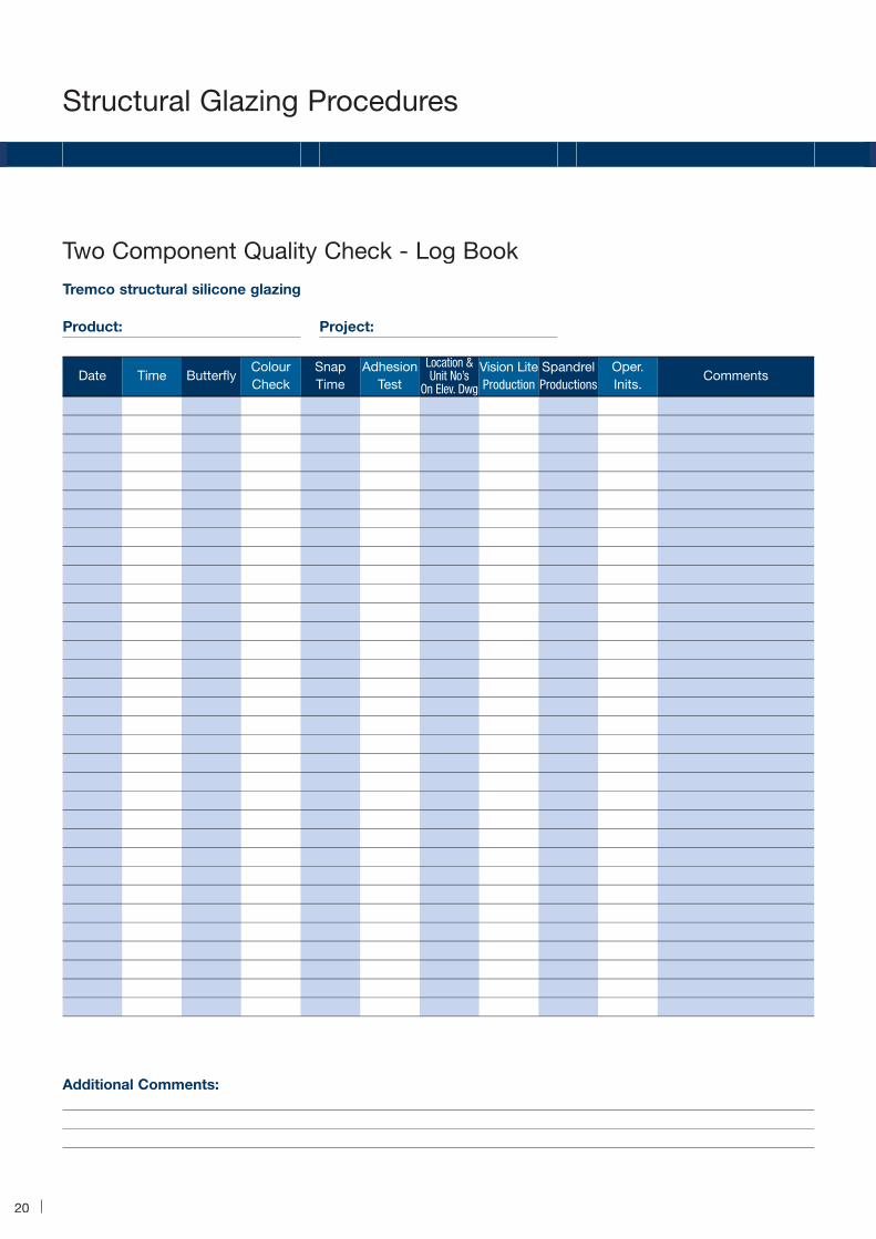
Two Component Quality Check - Log Book
Tremco structural silicone glazing
Product: Project:
Additional Comments:
Date Time ButterflyColourCheck
SnapTime
AdhesionTest
Location &Unit No’s
On Elev. Dwg
Vision LiteProduction
SpandrelProductions
Oper.Inits.
Comments

21
Dispensing of Proglaze II, or any plural
component product, at a correct,
recommended ratio as specified by
the sealant manufacturer is critical not
only to the initial cure of the sealant
but also its long-term performance
characteristics.
Recognizing the critical nature of
this requirement, plural component
equipment manufacturers have striven
to engineer equipment such that a
network of system checks provide
indication of malfunction or the need
for maintenance. In addition, the
sealant manufacturers have further
reviewed these systems to provide
other methods of analytical verification of
optimum equipment performance in order
to ensure that the product dispensed is
within recommended ratio levels.
This report attempts to describe the
most commonly used methods of in-plant
ratio verification for plural component
sealant systems. For specific equipment
diagnosis and service, refer to the
manufacturer manual.
The most commonly used system
for dispensing of Proglaze II is a
fixed ratio type metering system.
Essentially, this means that the system
does not allow for in-line ratio
adjustments. The systems employ two
hollow cylinders (one each for the base
and catalyst) which are honed out to
the respective base and catalyst
volumetric ratios. In operation, the
sleeves are filled and emptied
simultaneously via opposing sides of
the “cup seals” or “piston assembly”.
Volumetric ratio changes are
accomplished by replacing the catalyst
sleeve with one of a smaller inside
diameter which will deliver less
catalyst, or a larger inside diameter
sleeve which will deliver more catalyst
to the system. In the fixed ratio system,
the base component is constant.
Volumetric and/or weight ratios are
normally specified by the sealant
manufacturer. In most cases, the
sealant manufacturer has an established
relationship with the equipment supplier
who, in turn, has developed sealant
specific pump systems which ensure
proper sealant dispensing, metering
and mixing given the unique
characteristics of that sealant. Variables
which may effect pump specification
include sealant component viscosity,
flow characteristics, volumetric ratio
and mixing ease. When ordering
equipment for a specific plural
component sealant or when switching
from one sealant supplier to another,
it is critical that the user work closely
with the equipment manufacturer and
sealant supplier to ensure that proper
equipment configuration exists.
1. The use of snap time testing
This method may not be reliable as
sealant snap times are temperature and
humidity variable. Unless the sealant
was mixed and dispensed in a 25ºC
(77°F) / 50% RH environment, the snap
time will vary from the value stated on
the data sheet. This method should not
be used as a prime indicator of sealant
mix ratio evaluation but should be used
in conjunction with all the other methods
covered so far.
2. Ratio checks by using thecomponent delivery lines
The component feed lines are
disconnected from the mixing/dispensing
gun. Using two pre-weighed containers,
base and catalyst components are
dispensed into respective containers for
an equal period of time. For fixed ratio
systems such as Pyles 8900 series
dispensing system, we recommend that
the interval of time be equal to the travel
time of a single meter changeover.
A sample should be taken in each
direction of travel (left to right and right
to left), that way the integrity of the
meter system can be thoroughly
confirmed. Additionally, a sample
should be taken which includes one
downstroke, one upstroke and two
changeovers. After dispensing, the
respective components are individually
weighed and the initial container weight
subtracted.
On Ratio Verification Techniques
Recommended Methods of ConfirmingOn-Ratio Disensing of Tremco Proglaze II

22
Structural Glazing Procedures
Divide the base component weight by
the catalyst component weight to
calculate the weight ratio.
Example: For Proglaze II, a volumetric
ratio of 11.17:1 is equivalent to an
10.68:1 weight ratio. A base sample
weight 42.8 grams divided by a catalyst
component weight of 4 grams calculates
out to an 10.7 weight ratio. This is
acceptable and well within experimental
error. Variances approaching or in
excess of 10% may indicate the need
for equipment maintenance or improper
test procedures.
Repeat the test process and recalculate
values. Note that similar discrepancies
in either meter direction values or
stroke direction values indicate poor
performance of the system. This
would confirm the need for corrective
maintenance procedures. Contact
the equipment supplier for proper
recommendations.
3. The use of mixing equipmentpressure gauges as indicators ofproper equipment performance
Plural component mixing equipment
pressure gauges are excellent
indicators of proper equipment
performance. On fixed ratio systems,
the base meter pressures should
always read greater than those of the
catalyst by approximately 300-500 psi.
Variances between the paired gauges
(base meter and catalyst meter) should
be minimal; 100-300 psi. Variances in
excess of 300 psi would indicate either
a system blockage or wear of internal
meter parts. Both result in continuous or
intermittent ratio imbalance. If abnormal
or fluctuating pressures are noted,
contact the equipment manufacturer
for service recommendations.
4. The material displacementcalculation
It is the easiest method of on-ratio
verification. This method requires no
equipment disassembly, no weight
measurements or clean up. Through the
measurement of follower plate travel on
the base and catalyst components, we
calculate the volume of material used.
This method is as follows:
Inside diameter of catalyst pail
= 11.25" divided by 2= 5.625"
Inside diameter of base drum
= 22.50" divided by 2 = 11.25"
Area of a circle calculation
= 3 .1416 x radius2
Area of catalyst pail
= 3.1416 x 5.625in2 = 99.40in2
Area of base drum
= 3.1416 x 11.25in2 = 397.60in2
The previous values represent
calculation constants to be used
in the ratio evaluation.
Assume the following values for the
follower plate travel in this example
(note that source of travel measurements
are indicated on the attached sheet.)
Base: 5.625 (59/16")
Catalyst: 1.875 (17/8")
Given this information, base material
displacement equals 397.6in2 times
5.625" which is 2211.65 cubic inches.
Catalyst material displacement is 99.4in2
times 1.875" which equals 186.375
cubic inches. Now, to calculate ratio,
divide the base volume displacement
by the catalyst volume displacement:
2211.65 divided by 186.375
equals 11.98:1
This would indicate acceptable ratio
dispensing on a product type basis. Note
that this purging has an effect on the
final value of the equation, but minimal
purging over a significant production
run will usually provide a satisfactory
indication of proper equipment
performance and sealant ratio.
In any case, when a question of
equipment or sealant performance
arises, it is recommended that the user
consult with either or both parties such
that proper determination of the
problem is made and implementation
of an effective solution is established.
Structural glazingproject initiation form
Project title:
Project size:
Project location:
Architect:
Consultant:
Fabricator:
Glazing subcontractor:
Caulking subcontractor:
Glazing start date:
Glazing completion date:

23
Structural Glazing Calculations
kg/m2: SCD =
Short Span (m) x Windload (kg/m2)
28
N/m2: SCD =
Short Span (m) x Windload (N/m2)
276
KPa: SCD =
Short Span (m) x Windload (KPa)
0.276
PSF: SCD =
Short Span (ft) x Windload (PSF)
480
Minimum SCD = 6 mm
Structural IG Secondary Seal:
SCD ÷ 2 + 3 mm (4 sided)
SCD ÷ 2 (2 sided)
Minimum SCD = 6 mm
Different Glass Thickness:
SCD (2 sided)
SCD + 3 mm (4 sided)
Minimum SCD = 6 mm
Current industry practice determines
the Surface Contact Depth (SCD) of the
structural silicone sealant beads by
means of trapezoidal load distribution.
The SCD is given by the equation:
Triangles
SCD = 1/2 xW x X
12 x S
W = design negative windload (psi)
X = greatest short dimension of lite
for each design windload (ft)
S = mazimum stress allowed to act
on the structural sealant at
design windload
(the industry standard for “S” is 20 psi)
therefore:
SCD = 1/2 xW x X
12 x 20
SCD =W x X
480
CalculationsSilicone ContactDepth (Tensile Bead) SCD =
Windload (kg/m2) x Hypoteneuse side (metres)
28
X
1
1 1
Tan (a/2)+
Tan (b/2)
Side A = 2.5 metres
Angle a = 60°
Angle b = 30°
Windload = 150 kg/m2
therefore:
SCD =150x2.5
x1
28 1+
1
Tan(60/2) Tan(60/2)
SCD = 13.4 x1
1+
1
0.577 0.268
SCD = 13.4 x1
5.46
SCD = 2.455 (Minimum of 6 mm)
Structural sealantStructural sealant
Spacer
a
b
A
SCDSCD
Faceclearance
(thickness)

24
Structural Glazing Calculations
(Same as triangles)
NB: The side used should be the
largest quadrilateral side
(where both angles are below 90°).
Irregular Quadrilaterals
(Same as rectagles)
SCD =
Short Span of Largest Lite (m) x Windload (kg/m2)
28
Regular Quadrilaterals
(minimum of 6 mm)
(minimum of 6 mm)
Nokia Headquarters, Espoo, Finland
Danube House, Prague, Czech Republic

25
Appendix A
Conversion Table - Wind Pressure and Speed
Pressure
Pa lb f/ft2 mm H2O in H2Om/s km/h mph
50
100
150
200
250
300
350
400
450
500
550
600
650
700
750
800
850
900
950
1000
1200
1400
1600
1800
2000
2200
2400
2600
2800
3000
1.04
2.09
3.13
4.18
5.22
6.27
7.31
8.35
9.40
10.44
11.49
12.53
13.58
14.62
15.66
16.71
17.75
18.80
19.84
20.89
25.06
29.24
33.42
37.59
41.77
45.95
50.12
54.30
58.48
62.86
Speed
9.0
12.7
15.5
18.0
20.1
22.0
23.8
25.4
27.0
28.5
29.8
31.1
32.5
33.6
34.8
36.0
37.1
38.2
39.2
40.2
44.1
47.7
50.9
54.0
58.9
59.7
62.3
64.8
67.4
69.8
32.5
46.0
56.3
65.0
72.7
79.7
85.9
91.9
97.5
102.8
107.8
112.6
117.2
121.7
125.9
130.0
134.1
137.9
141.8
145.3
159.2
172.0
183.9
195.1
205.5
215.7
225.1
234.3
243.2
251.7
20.2
28.6
35.0
40.4
45.2
49.5
53.4
57.1
60.6
63.9
67.0
70.0
72.8
75.6
78.2
80.8
83.3
85.7
88.0
90.3
98.9
106.9
114.3
121.2
127.7
134.0
139.9
145.6
151.1
156.4
Water Gauge
5.1
10.2
15.3
20.4
25.5
30.6
35.7
40.8
45.9
51.0
56.1
61.2
66.3
71.4
76.5
81.6
88.7
91.8
96.9
102.0
122.4
142.8
163.2
183.6
204.1
224.5
244.9
265.3
285.7
306.1
0.2
0.4
0.6
0.4
1.0
1.2
1.4
1.6
1.8
2.0
2.2
2.4
2.6
2.8
3.0
3.2
3.4
3.6
3.8
4.0
4.8
5.6
6.4
7.2
8.0
8.8
9.6
10.4
11.2
12.0
NOTE: The above conversions are based on the aerodynamic relationship:Pressure = (velocity)2 x (a constant) eg. P(mm.wg) = (V m/s)2 x 0.063 or P(lbf/ft2) = (V mile/h)2 x 0.00258

26
Appendix B
Expansion Joint End DamsMetal JoineryPerimeter JointsOther
PROJECT #:Sample Sent:Received:Prepared:Estimated:Completion:Completed:Report Issued:
Sales Rep: Customer Territory: Address: City: State: Job Name: Contact: Address: Architect: City: State: Consultant:Bldg. Type: Contractor: Estimated Footage: Applicator:
VerticalSlopedConventional ( toe heel cap)Structural ( butt 2-sided 3&4-sided 4-sided visuline)Weather BeadTensile Bead Field GlazedShop Glazed Other
METALS: MASONRY: NATURAL STONE: Aluminum Brick Granite Extruded Glazed Limestone Sheet Unglazed Slate Steel GFRC Marble Rolled Concrete Surfaces to test: Sheet Precast Polished Stainless Steel PIP/CIP Flame Finish Galvanized Form Cut Edge Other Concrete Block Face Other BackFINISHES: CLASS: OTHER: Paint Mfr. Color Number Trade
Anodized Black (315) Bronze (311. 312. or Clear (205RI. or
Mfr.
GLAZING APPLICATION? Yes NoMillOther
SEALANT APPLICATION:
Monolithic PVCLaminated FiberalassInsulated AcrvlicSpandrel PolycarbonateReflective WoodOther EIFS
Technical Services Laboratory Evaluation Request
SUBMITTED SAMPLE DESCRIPTION
An Company
Courier To:

27
TEST PROCEDURES
SEALANTS
PRIMERS
ADDITIONAL COMMENTS:
Tab Adhesion
ASTMC 1087
ASTMC 1248
ASTMC 794
ASTMC 510
Spectrem 1
Spectrem 2
Spectrem 3
Spectrem 4TS
Proglaze
Proglaze ll
Proglaze SSG
Tremsil 200
Tremsil 500
Tremsii 600
Dymonic
Dymonic FC
Dymonic NT
Dymeric 240
Dymeric 240 FC
THC 900
THC 901
HPL
Tremco 830
Tremflex 834
Butyl
Mono 555
Vulkem 116
Vulkem 921
PL 400
IPA
MEK
XYLOL
Wire Brush
Grind
Other tests: (describe in additional comments box)
SILICONE: URETHANES: OTHER: SOLVENTIPREPS:
TREMprime Porous
Silicone Primer
Deckline
191
181171
6
10
23
171
INCLUDE SKETCH OF SAMPLE
28
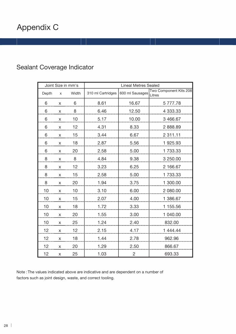
Appendix C
Sealant Coverage Indicator
Joint Size in mm's
Depth x Width 310 ml Cartridges 600 ml SausagesTwo Component Kits 208 Litres
6 x 6 8.61 16.67 5 777.78
6 x 8 6.46 12.50 4 333.33
6 x 10 5.17 10.00 3 466.67
6 x 12 4.31 8.33 2 888.89
6 x 15 3.44 6.67 2 311.11
6 x 18 2.87 5.56 1 925.93
6 x 20 2.58 5.00 1 733.33
8 x 8 4.84 9.38 3 250.00
8 x 12 3.23 6.25 2 166.67
8 x 15 2.58 5.00 1 733.33
8 x 20 1.94 3.75 1 300.00
10 x 10 3.10 6.00 2 080.00
10 x 15 2.07 4.00 1 386.67
10 x 18 1.72 3.33 1 155.56
10 x 20 1.55 3.00 1 040.00
10 x 25 1.24 2.40 832.00
12 x 12 2.15 4.17 1 444.44
12 x 18 1.44 2.78 962.96
12 x 20 1.29 2.50 866.67
12 x 25 1.03 2 693.33
Note : The values indicated above are indicative and are dependent on a number of
factors such as joint design, waste, and correct tooling.
Lineal Metres Sealed

Product Selection
Proglaze II is a high performance, twocomponent, neutral curing silicone sealant,developed specifically for in plant structuralglazing application.
common glazing substrates:
glass, aluminium, etc.
Tremco JS562 is a high modulus, two-component, elastomeric, neutral curingsilicone sealant specifically developed forin-plant IG unit manufacturing especially instructural glazing applications.
Available in polyurethane JS442 suitable
structural applications.
JS 680 is a primary sealant for dual seal IGsystems fully compatible with both JS562 JS 442 sealants
Tremco SG300 Spectrem 2 is a versatile,high performance structural grade onecomponent sillicone ideal for a widevariety of general purpose joint sealing andstructural glazing applications
FS500 is a one-part neutral curing,low modulus, low odor silicone sealantsuitable for joint sealing applications tomost porous and non-porous substratesincluding masonry, brick, aluminum,
agent.
agent.
600 ml sausage (20 per case)
600 ml sausage (20 per case)
Charcoal Grey
Charcoal Grey
Black
Black, White, Grey - Other Colours - subject to
Proglaze II
JS562 / JS442
JS680
SG300 Spectrem 2
Packaging
Packaging
Packaging7kg cylindrical slug
ColourBlack
Packaging
Packaging
Colour
Colour
Colour
Colour
29
c
wood, glass and glazed surfaces.
illbruck
FS500 Frame and Facade Silicone

Illbruck SP030 is a transparent, fast-curing adhesive-sealant based on Tremco illbruck’s SP hybrid formulation. It cures
seal.
illbruck FA600 is a gun-grade, neutral cure silicone sealant with fungicide. It cures rapidly to form a permanently flexible and extremely durable watertight seal.
with a micro-cellular structure designed
SP030 Fix & Seal Crystal
FA600 Frame Silicone
SGT635 Tape
MT440 High Grip Original
ME402 Compriband Ali-Tape PB
ME220 EPDM Membrane
Packaging
ColourCrystal Clear
Packaging
Colour
PackagingAvailable in a wide variety of sizes with pressuresensitive adhesive on one or two sides. Supplied with a protective release liner covering the adhesive coated surface.
ColourBlack
Packaging
ColourBuff
Packaging
ColourSilver foil
Packaging
ColourBlack
30
310ml cartridge or 600ml sausage
Available in translucent, white, brown, grey and black.Additional colours available upon request.
T635 Structural Glazing Tape is a
specifically for use as a compatible spacer for structural glazing.
illbruck MT440 is a versatile, high strength grab adhesive based onsynthetic rubber and resins. Excellentadhesion to a wide variety of substrates and ideal for bonding uneven surfaces.
310ml or 380ml cartridges
illbruck ME402 is a high-performance sealing tape consisting of a plasto-elastic butyl rubber adhesive/sealantapplied to one side of an aluminisedpolyester film. Ideal for sealing jointsthat need to be impervious to gas andwater vapour diffusion.
Thickness of 0.7mm and widths of 50mm, 100mm, 150mm ex. stock. Other sizes available upon request.
illbruck ME220 is an EPDM-based membrane used for sealing interfaces to provide airtight or weathertight seals. It hasexcellent movement capability and resistance to mechanical damage.
Thickness of 0.75mm and widths of 1300mm, 25m roll. Can be cut to suit your requirements.

35
Client
Mr Khaled Abdul Rahim, Al Attar
Architect
Adnan Saffarini
Date of completion
November 1998
Curtain wall contractor
Al Abbar Aluminium
Tremco products used
Spectrem 2
High performance, neutral cure
silicone sealant.
SGT 920 Tape
High density urethane foam tape
spacer for structural glazing.
JS 562
Silicone sealant for IG manufacture.
JS 780
Primary sealant for dual seal
IG systems.
EPDM Settting Blocks
Sealant Backer Rod
Special project features
2-sided structural glazing completed
with Spectrem 2 and SGT 920 Tape. IG
manufactured with JS 562 and JS 780.
Al Attar Tower II - Sheikh Zayed Road, Dubai, U.A.E.
Client
HRH General Sheikh Mohammed
Bin Rashid Al Maktoum (Crown Prince
of Dubai)
Architect
Norr Group Consultants
Date of completion
April 2000
Main contractor
Besix - Ssangyong JV
Curtain wall contractor
Al Abbar Aluminium
Tremco products used
Proglaze II
High performance, multi-component
structural silicone.
Tremsil 500
A one part neutral curing low
modulus silicone sealant.
Spectrem 2
High performance, neutral cure
silicone sealant.
Dymeric
High performance polyurethane
expansion joint sealant.
Dymonic
One component low modulus
polyurethane expansion joint sealant.
SGT 920 Tape
High density urethane foam tape
spacer for structural glazing.
Gaskets
High performance EPDM and
Silicone extrusions
Special project features
2-sided structural glazing - unitised
system.
Emirates Towers Hotel - Sheikh Zayed Road, Dubai, U.A.E.

Fraser Global Trading (Pty) LtdUnit No. 1, Meadowbrook Park,North Reef Road, Germiston.
FG Trading -Your Trading PartnerFG Trading Pty Ltd is the Authorised Sole Distributor of Tremco Illbruck glazing products across Southern Africa and serves the glass and glazing markets by providing innovative system based products and solutions. FG Trading in partnership with Tremco Illbruck are dedicated to providing technical solutions to ensure increased reliabilityand longer life for building envelopes. The extensive product range includes sealants for uPVC, aluminium, timber windows and structural glazing, and for the production of high quality insulating glass units, in addition there are adhesives, glazing tapes, mirror mounting tapes, façade membranes and silicone gaskets. All products are routinely and rigorously tested to ensure they meet current or imminent legislation giving you the security and peace of mind of knowing you are buying a quality, reliable product.
P.O. Box 2976, Bedfordview 2008Johannesburg, South AfricaTel +27 11 450 0263
Fax +27 11 450 0306Email [email protected] www.fgtrading.co.za
INDIANRWANDA
BURUNDI
DEMOCRATICREPUBLIC
OF THE CONGO
CENTRALAFRICAN
REPUBLIC
OCEAN
KENYA
TANZANIA
MADAGASCARMOZAMBIQUE
MALAWI
ZAMBIA
ANGOLA
CAMEROON
GHANA
BENIN
UGANDA
NIGERIA
NAMIBIA
SOUTH
ATLANTIC
OCEAN
BOTSWANA
ZIMBABWE
SWAZILANDLESOTHO
SOUTHAFRICA
INDIAN
OCEAN
EQUATORIALGUINEA
GABON
REP. OFTHE
CONGO
TOGO