By: Joe Sousa Gabriela Vieira Eize Vieira Amy Williams Adam Spencer James Jepsen.

z
2012
Photovoltaic Simulator
User Manual InteGrid Lab – EECL, CSU

InteGrid Photovoltaic Simulator
Page | 2
This manual was originally written by Peter Vieira from the 2009-2010 Senior Design Team. Major revisions were made by Andrew Geck from the 2011-2012 Senior Design Team. This manual is intended to provide an overview of the hardware and software associated with the Photovoltaic (PV) Simulator so that anyone unfamiliar with the system can have some understanding of how the system operates, of how to run a simulation, and of how to collect and observe the output data from the system. For more detailed information on the underlying theory and system operation, please consult the following files which should be located on the lab PC in the "C:\PV Simulator Documentation\Reports" folder: PVEmulatorDocumentation.pdf -- "Adapting King’s Model to Design a DC Bus Photovoltaic Emulator." Written by Joel Nelson. Summer 2009. InteGridFinalReport2010.pdf -- "Final Report: InteGrid ~ Photovoltaic Simulator" Written by B. Ambon, M. Fox, J. Taylor, P. Vieira. May 2010. PVFallReport2011.pdf -- "Grid Tied Photovoltaic Simulator" Written by Andrew Geck. Fall 2011. PVSpringReport2012.pdf -- "Grid Tied Photovoltaic Simulator: Final Report" Written by Andrew Geck. Spring 2012.
InteGrid Photovoltaic Simulator
Page | 3
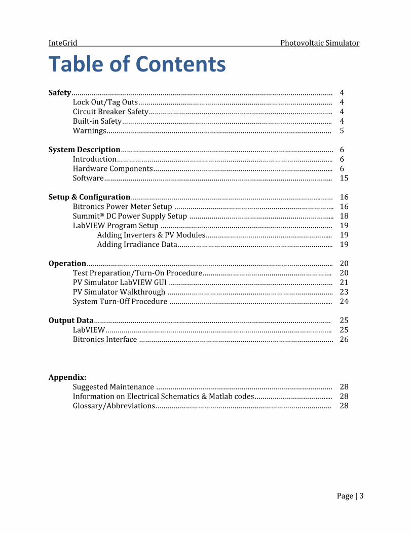
Table of Contents Safety………………………………………………………………………………………………………………… 4 Lock Out/Tag Outs…………………………………………………………………………………… 4 Circuit Breaker Safety………………………………………………………………………………. 4 Built-in Safety………………………………………………………………………………………….. 4 Warnings………………………………………………………………………………………………… 5 System Description…………………………………………………………………………………………… 6 Introduction…………………………………………………………………………………………….. 6 Hardware Components…………………………………………………………………………….. 6 Software………………………………………………………………………………………………….. 15 Setup & Configuration………………………………………………………………………………….…… 16 Bitronics Power Meter Setup ……………………………………………………………………. 16 Summit® DC Power Supply Setup ……………………………………………………………... 18 LabVIEW Program Setup …………………………………………………………………………. 19 Adding Inverters & PV Modules……………………………………………………... 19 Adding Irradiance Data………………………………………………………………….. 19 Operation………………………………………………………………………………………………………….. 20 Test Preparation/Turn-On Procedure………………………………………………………. 20 PV Simulator LabVIEW GUI ……………………………………………………………………… 21 PV Simulator Walkthrough ………………………………………………………………………. 23 System Turn-Off Procedure ……………………………………………………………………... 24 Output Data……………………………………………………………………………………………………… 25 LabVIEW…………………………………………………………………………………………………. 25 Bitronics Interface …………………………………………………………………………………… 26 Appendix: Suggested Maintenance …………………………………………………………………………… 28 Information on Electrical Schematics & Matlab codes………………………………... 28 Glossary/Abbreviations…………………………………………………………………………… 28

InteGrid Photovoltaic Simulator
Page | 4
Safety The Photovoltaic Simulator is equipped with safety in all parts of the system in order to protect the system and its operators. It was built according to National Electrical Code. The photovoltaic systems section of the code, Article 690, was used to ensure adequate installation and safety measures. Lock Out/Tag Outs
• The 480VAC PV Simulator 80A Fused Disconnect fed from CBPB01 must be locked out/tagged out whenever the PV Simulator is not in use. • Lockout/tagout procedures must be adhered to on all outgoing circuit breakers connected to the power grid or InteGrid when not in use.
Circuit Breaker Safety • All circuit breaker and disconnect doors must be bolted or latched shut at all times to prevent possible harm to operators or the system. • The 24V battery supply from the InteGrid switchgear must be connected at all times for the safety circuit to work.
Built-in Safety Any of the following actions will activate the safety circuit, triggering the shunt trips on all of the Eaton/Cutler-Hammer AC breakers, thereby powering down and isolating the system from the 480V and 240V sources: • Pressing the Emergency-Stop button on the outside of the control cabinet. • Pressing the Emergency-Stop button on the LabVIEW front panel while the program is running. • Removing the DC or AC connection covers on the Summit® DC Power Supply while power to the 24V circuit is connected. • If the 120V power to the PV Simulator control cabinet fails. • If the 480V AC input voltage to the Summit® DC Power Supply drops below 354VAC. • If the Bitronics power meter is configured to activate a digital output when the AC current exceeds a given limit, it will activate a relay. This limit should be set to the maximum AC output current for the inverter being operated to improve the safety of operation.

InteGrid Photovoltaic Simulator
Page | 5
Warnings
• The fan switch to the Preload Resistor Bank must always be on while DC output power is on in order to cool the resistors and prevent overheating. • Each Preload Resistor Bank (5 resistors each) contains an inline fuse which is located in their respective DC disconnect box. These fuses must be open and the DC disconnect must be open to conduct maintenance on the Preload Resistor Banks. • Check for latent voltage before conducting maintenance on any device. The DC supply and inverters contain large capacitors which store charge and could be dangerous for several minutes after power is removed. • A common ground runs from the 480V Main Distribution Panel to the entire PV Simulator, including the frame, boxes, cabinet, conduit and devices. Do not touch any hot lines to any of these pieces of metal or a short will occur. • Do not operate the output of the Summit® DC Power Supply above 600V nominal. This would exceed the voltage rating of the cables used for the DC connections and the inverter maximum input limits. • The Bitronics power meter must be configured to trip its output relay to the shunt trip circuit at the max AC output current of the inverter under test to ensure maximum safety of operation. • The Bitronics power meter measures non-scaled voltage, therefore caution must be taken when around the voltage terminals on the meter or possible injury could result. These terminals will have 480V or 240V on them when live.
InteGrid Photovoltaic Simulator
Page | 6
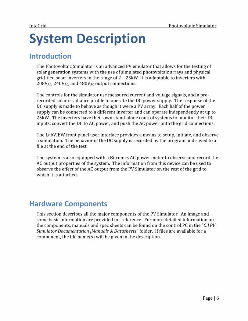
System Description Introduction The Photovoltaic Simulator is an advanced PV emulator that allows for the testing of solar generation systems with the use of simulated photovoltaic arrays and physical grid-tied solar inverters in the range of 2 – 25kW. It is adaptable to inverters with 208VAC, 240VAC, and 480VAC output connections. The controls for the simulator use measured current and voltage signals, and a pre-recorded solar irradiance profile to operate the DC power supply. The response of the DC supply is made to behave as though it were a PV array. Each half of the power supply can be connected to a different inverter and can operate independently at up to 25kW. The inverters have their own stand-alone control systems to monitor their DC inputs, convert the DC to AC power, and push the AC power onto the grid connections. The LabVIEW front panel user interface provides a means to setup, initiate, and observe a simulation. The behavior of the DC supply is recorded by the program and saved to a file at the end of the test. The system is also equipped with a Bitronics AC power meter to observe and record the AC output properties of the system. The information from this device can be used to observe the effect of the AC output from the PV Simulator on the rest of the grid to which it is attached. Hardware Components This section describes all the major components of the PV Simulator. An image and some basic information are provided for reference. For more detailed information on the components, manuals and spec sheets can be found on the control PC in the "C:\PV
Simulator Documentation\Manuals & Datasheets" folder. If files are available for a component, the file name(s) will be given in the description.

InteGrid
S(S In O
Front of F
Exterior
d ummit® DCS/N 673426ConveIt is cconnenput: 480V Output: Mini Maxi
unit.
used DC DiLocatinvert
of Disconn
C Power Su6, M/N 315erts incominontrolled byected to the3Φ AC. imums: 100imums: 250
Back
isconnects ted betweenters.
ects.
upply – 25k2700-204Bng 480V 3Φy the N.I. cD control PC 0W, 50V, 1A000W (each
of unit.
(x2) – 600Vn the DC out
kW x 25kW B) Φ AC into twDAQ throughfor setup anA h side), 1000 Fil"SuUs "Su
V rated tput of the s
Int
Dual Outpwo independh the user cnd configur
0V, 83.3A les: ummit 25kser Manual.Pummit VFP
supply and t
terior of Dis
Photovoput dent DC sourables. A serration purpo
kW x 25kWPDF" User Manu
the connect
sconnects.
oltaic Simula
Pag
rces. rial cable is oses only.
W 57000015al.PDF"
tions to the
ator
ge | 7
5-00B
InteGrid
P(S M a co th
F N d P(S M a co
F N d
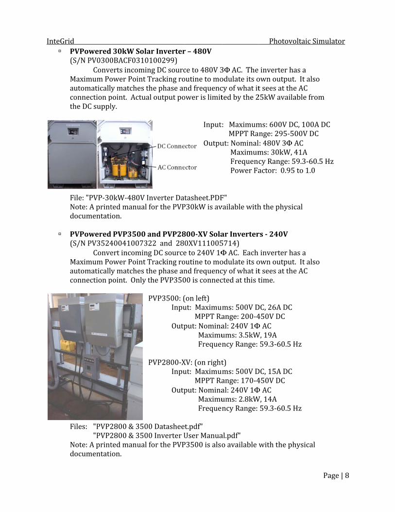
d PVPoweredS/N PV0300ConveMaximum Poutomaticallonnection phe DC suppl
ile: "PVP-30Note: A printocumentatiPVPoweredS/N PV3524ConveMaximum Poutomaticallonnection p
iles: "PVP2"PVP2Note: A printocumentati
d 30kW Sola0BACF0310erts incominower Point Ty matches tpoint. Actualy.
0kW-480V Ited manual ion. d PVP3500 a400410073ert incominower Point Ty matches tpoint. Only
2800 & 3502800 & 350ted manual ion.
ar Inverter0100299) ng DC sourcTracking rothe phase anal output po
Inverter Datfor the PVPand PVP2822 and 28g DC sourceTracking rothe phase anthe PVP350 PVP3500: ( Inpu Outp PVP2800-X Inpu Outp 0 Datashee0 Inverter Ufor the PVP
r – 480V ce to 480V 3outine to mond frequencower is limit
InputOutpu tasheet.PDFP30kW is av800-XV Sola0XV111005e to 240V 1Φoutine to mond frequenc00 is connec(on left) ut: MaximuMPPT Raput: Nomina Maximu FrequeXV: (on rightut: MaximuMPPT Raput: Nomina Maximu Freque t.pdf" User ManuaP3500 is also
3Φ AC. The odulate its ocy of what itted by the 2t: Maximum MPPT Raut: Nominal Maximum Frequenc Power FaF" vailable withar Inverter5714) Φ AC. Each odulate its ocy of what itcted at this tms: 500V Dange: 200-4al: 240V 1Φums: 3.5kWncy Range: t) ms: 500V Dange: 170-4al: 240V 1Φums: 2.8kWncy Range:
al.pdf" o available
Photovo inverter haown output.t sees at the25kW availa
ms: 600V DCnge: 295-50l: 480V 3Φ Ams: 30kW, 4cy Range: 5actor: 0.95 h the physicrs - 240V inverter haown output.t sees at thetime. DC, 26A DC 450V DC Φ AC W, 19A 59.3-60.5 HDC, 15A DC 450V DC Φ AC W, 14A 59.3-60.5 H
with the ph
oltaic Simula
Pag
as a . It alsoe AC able from C, 100A DC00V DC AC 41A 9.3-60.5 Hzto 1.0 cal as a . It alsoe AC
Hz
Hz hysical
ator
ge | 8
z

InteGrid
Ash
C T
2
T
d AC Circuit Bhown) – Cu
Control PC The computeloccabon Ins Fil
4V BatteryThis is the so
Breakers – 2tler-Hamme
er controls tcated in theble connectn the DC supstalled SoftwWindole: "JPK Des
y Supply ource for th
208VAC 3φ, er breakers Ththtriiso Fi"C"S
the simulato main contrted to the DCpply. ware: ows 7, Matlaktop Compu
e 24V safety These brthe basemto a charthis breacontrol c
240VAC 3φ, with shunthese are thehe main AC ip modules olate these sles: Circuit Breakhunt Trip-C
or through rol cabinet. C supply forab 2009, Labuter.pdf"
y and controeakers are lment. Theyger located aker to the pabinet of th
480VAC 3φt trip accesse points of supply for are activatsources froker-Cutler-HCutler-Hamm
communicaIt also has ar configuratbVIEW 2009
ol circuits folocated in thy are suppliebehind SG3point of connhe simulator
Photovo A, 480VAC 3sory. connection the simulated by the m the simulHammer I.Lmer I.L.29C
ation with tha serial comtion and set9.
or the simuhe third seced from a ba3B. The sounection insir.
oltaic Simula
Pag
3φ Main (noto InteGridator. The ssafety circulator.
L.29C101G.PC140F.PDF"
he N.I. cDAQmmunicationtup of the lim
lator. ction of SG3attery attacurce runs froide the main
ator
ge | 9
ot d and shunt uit to PDF"
Q n mits
B in hed om n
InteGrid
M
Exterior The main1. Stack m2. Emer a3. Bitron4. Fuse b5. 15V D6. 120V 7. Unint8. Conne9. Natio10. User11. 24V 12. CT S13. Link TOnly opeprecauticabinet.
d Main Contro
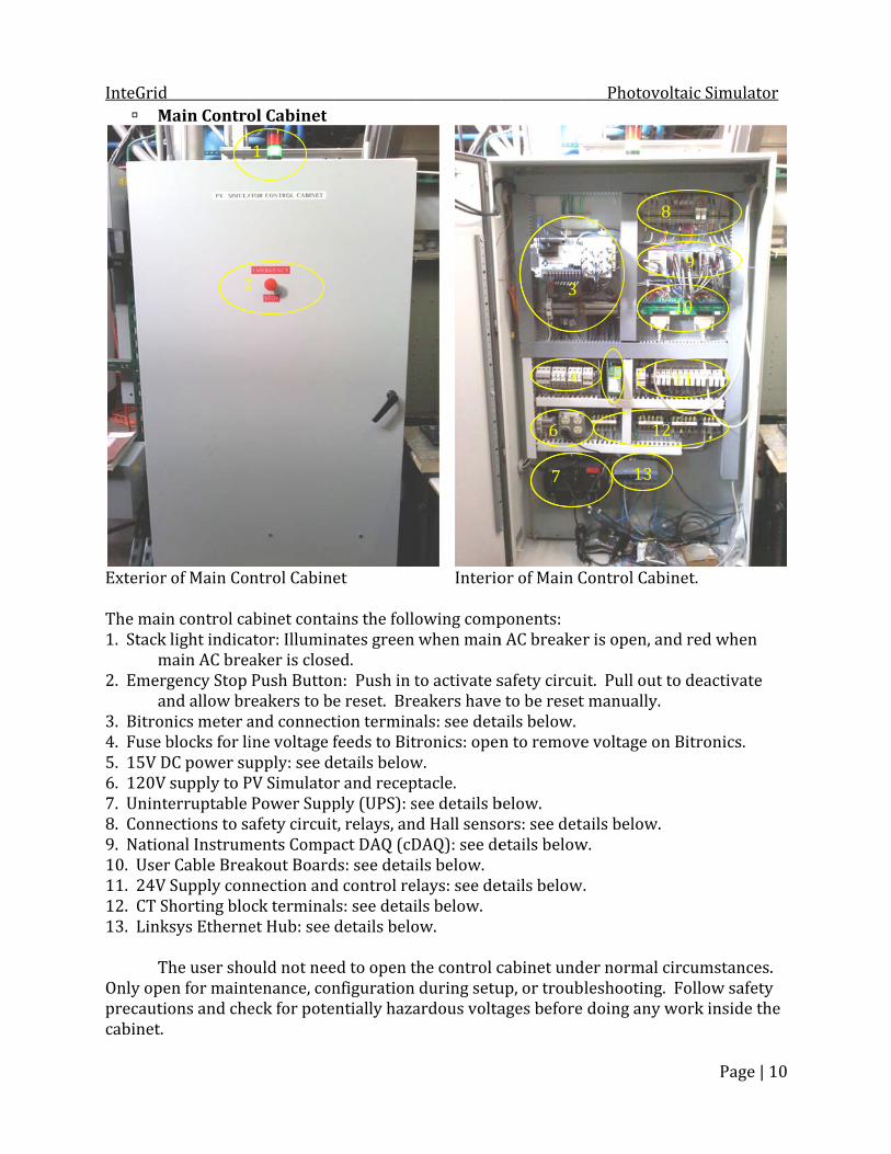
of Main Conn control calight indicamain AC breagency Stop nd allow brnics meter ablocks for liDC power susupply to Pterruptable ections to sanal Instrumr Cable BreaSupply conShorting bloksys EtherneThe user shoen for maintons and che
2
ol Cabinet
ntrol Cabinabinet contaator: Illuminaker is closePush Buttoreakers to band connectine voltage fupply: see dPV SimulatoPower Suppafety circuitments Compaakout Boardnnection andck terminalet Hub: see ould not neetenance, coneck for pote
2
1
et ains the follonates green ed. n: Push in te reset. Bretion terminafeeds to Bitetails belowr and recepply (UPS): st, relays, anact DAQ (cDds: see detaid control rels: see detaidetails beloed to open thnfiguration entially haza
Interioowing compwhen mainto activate seakers haveals: see detaronics: openw. tacle. ee details bd Hall sensoDAQ): see deils below. lays: see deils below. ow. he control cduring setuardous volta
or of Main Cponents: n AC breakersafety circuie to be resetails below.n to removebelow. ors: see detaetails belowetails below.cabinet undup, or troubages before
34
67
Photovo
Control Cabir is open, anit. Pull out tt manually. e voltage onails below. w. .
der normal cleshooting. doing any w
5
8
1213
oltaic Simula
Page
inet. nd red whento deactivatn Bitronics.
circumstanc Follow safwork inside
8 9 10
11 2
ator
e | 10
n te
ces. fety e the

InteGrid
BT
F +
UT
d Bitronics MThe Bitronic
iles: "Bitro"Bitro+/- 15V PowThis susupply File: "15V P UninterruptThe UPS is a
572 Powers has a digit
onics M572 onics M57x wer Supply upply takes y for the HalPower Suppl
tible Powesingle phas
r Meter tal input consafto tterto tconbe mepro The480Datasheet.pUser Manua
– Phoenix 2a 120V AC il effect sensly - Phoenix
r Supply se 120V bac The controinto the batcDAQ is pluloss of the triggers the
nnection frofety circuit rthe hub in thrminals on tthe terminannections nedone at theeter itself. Totected by ae meter is p0V and 240Vpdf" al.pdf" 2938743 input and crsors on the x 2938743.p
kup and surol PC, monitottery backuugged into a120V source safety circ
om the cDArelay, and anhe cabinet. the meter haals located beed to be che terminals bThe 120V feea small 3A fupresently coV AC outpu
reates a posDC bus. pdf"
rge protectior, and the up ports on ta surge suppce removes pcuit.
PhotovoAQ, a digital n Ethernet c All the voltave short jubelow the mhanged, it isbelow ratheed to the muse. onfigured tot.
sitive and n
ion system. Linksys hubthe UPS. Thpression popower to th
oltaic Simula
Page
output to a cable connetage and CTumpers instameter. If anys suggested er than on theter is also o measure th
egative 15V
b are pluggehe supply foort. This wahe cDAQ, wh
ator
e | 11
ected T alled y this he he
V DC
ed or the ay, hich

InteGrid
R
N
The chas
The 920reduce tanalog in Files: "NI Com"NI9472
d Relays (x2)
National Insssis containNI 9472 8NI 9422 8NI 9472 8NI 9472 8Spare SloNI 9422 8NI 9263 4NI 9205 3
5 Analog Inhe effects onputs to 16.pactDAQ Da2-9474.pdf",
– Siemens 3
struments s the follow8-Channel 28-Channel 28-Channel 28-Channel 2ot 8-Channel 24-Channel, +32-Channel
nput modulef noise on th. atasheet.PD, "NI9422.p
3TX7110-5JOne of thby the cDterminalcircuit, ato the Ha File: "Sie CompactDAwing module24 V Sourcin24 V Sinking24 V Sourcin24 V Sourcin24 V Sinking+/-10 V, up +/-10 V, up
e has been che incomingDF", "NIcDApdf", "NI926
JC03 1NO/1hese relays DAQ. Both als to the leftand the termall effect senemens3TX7AQ-9178 es: ng Digital Oug/Sourcing ng Digital Oung Digital Oug/Sourcing to 100 kS/sp to 250 kS/ The cDAcontrol PLabVIEWcDAQ cosending attachedthe cDAQ There arterminalmodifica
configured tg signals. TAQ-9178.pdf63.pdf", "NI
1NC, 24V cois operatedare triggerst are the conminals to thensors locate71.pdf"
utput ModuDigital Inpuutput Moduutput ModuDigital Inpus, 16-Bit DA/s, 16-Bit ADQ chassis coPC through aW programsntrols the Dsignals throd to the breaQ. re a numberls available ation of the sto take diffehis effectivef " I9205.pdf"
Photovooil d by the Bitrs for the safennections toe right are ted in the DC
ule ut Module ule ule ut Module AC Analog ODC Analog Iommunicatea USB conns executed oDC power suough the useakout boardr of spare infor future esystem. erential meaely reduces
oltaic Simula
Page
ronics, the oety circuit. o the safety the connectC disconnect
utput Modunput Modules with the ection, and on the PC. Tupply by er cables ds located benput and outexpansion anasurements the numbe
ator
e | 12
other The ions ts.
ule le runs The elow tput nd to r of
InteGrid
U
File: "brk C
em File: "Au C
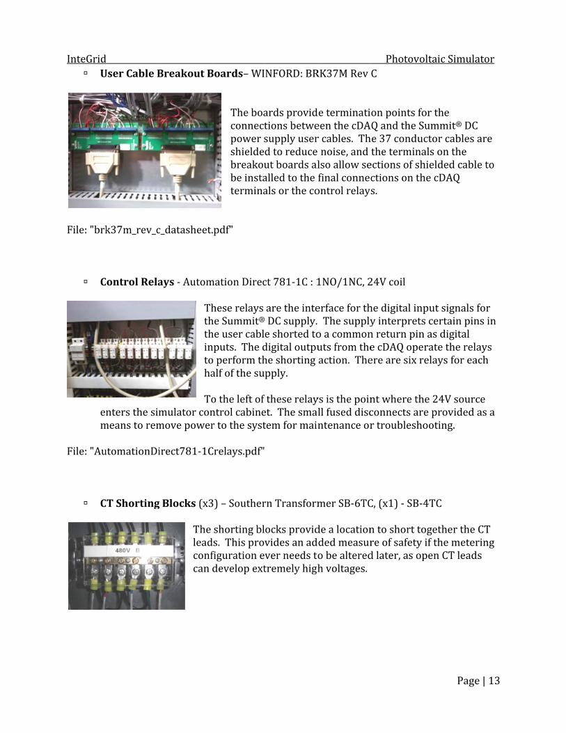
d User Cable B
k37m_rev_cControl Rela
nters the simmeans to remutomationDiCT Shorting
Breakout B
c_datasheet.ays - Autom Thththintoha Tomulator conmove powerirect781-1C
g Blocks (x3The leadconfcan
Boards– WI The boaconnectpower sshieldebreakoube instatermina .pdf"
mation Direchese relays he Summit®he user cablnputs. The do perform thalf of the suo the left of ntrol cabiner to the systCrelays.pdf"3) – Southershorting blds. This provfiguration edevelop ext
NFORD: BRards providtions betwesupply userd to reduceut boards alalled to the als or the co
ct 781-1C : 1are the inte DC supply. e shorted todigital outpuhe shorting pply. these relayet. The smatem for main rn Transformocks providvides an adver needs totremely high
RK37M Rev de terminatieen the cDAr cables. Th noise, and lso allow sefinal connecontrol relay
1NO/1NC, 2erface for th The supplyo a commonuts from theaction. Theys is the poinll fused discntenance or
mer SB-6TCde a locationded measuro be alteredh voltages.
PhotovoC
on points foAQ and the She 37 conduthe terminaections of shctions on ths.
24V coil he digital inpy interpretsn return pine cDAQ opeere are six rnt where thconnects arr troublesho
C, (x1) - SB-4n to short tore of safety d later, as op
oltaic Simula
Page
or the Summit® DCctor cables als on the hielded cablhe cDAQ
put signals s certain pinn as digital rate the relelays for eahe 24V source provided ooting.
4TC ogether the if the meterpen CT lead
ator
e | 13
C are le to
for ns in ays ach ce as a
CT ring ds

InteGrid
L
C
V
F H
d inksys Eth
Current Tra
Voltage Divi
ile: "VoltageHall Effect S
ernet Hub Providesystemthe EEC
ansformersTheconbloterm File iders (x2) –Thesdiscobus vdiscodowdevi e Dividers-H
Sensors (x2These are lprovide a danalog inpuFile: "Hall E
es Ethernet . The incomCL. s (x4) – Flexese are locannections tocks in the cminals on the: "Flex-Cor– Sustainablse are locateonnects. Thvoltage for onnects opewn voltage thce. HPVD-3-480) – Tamura ocated on thdirect measuut module in
Effect Senso
communicaming feed is
x-Core AL-10ted in the wo InteGrid. Tontrol cabinhe Bitronicse AL-101 CTle Automatied in the uphey provideeach half ofen during a hat could be0 DatasheetL03S100D1he positive urement of tn the cDAQ.
or - Tamura
ations to vaattached to 01, (100:5 Rwireway belThey are conet, and fros. Ts.pdf" ion HPVD-3pper DC wir a point to df the DC suptest. They ce used as ant.pdf" 15, (100A:4 DC lead in tthe DC bus L03100D15
Photovoarious devico the buildinRatio) ow the AC bnnected to m there, run
-480, (100:eway abovedirectly meapply withoutcan also pron analog sign
4V Ratio) the DC discocurrent tha5.pdf"
oltaic Simula
Page
es in the ng network
breaker the CT shorn to the CT
1 Ratio) e the DC asure the Dt having theovide a scalenal to anoth
onnects. That is sent to t
ator
e | 14
at
rting
C e DC ed her
hey the

InteGrid
P
F H
F
F SoftwThis Addi
d Preload Res TTin Etoile: "ResistoHeat Sinks (
ans (x3) – E
ile: "Fans - Eware is a list of ational detai LabVI Matla Summ BiView Config
sistors (x10These resistoThere are fivn parallel wEach resistorogether is aors - Huntin(x6) – ManuThe resisdissipatiOne of thpossible EBM-Papst The fansinks anthe prelDC supp EBM Papst ll the majorls on each pIEW 2009 - ab 2009 - fromit Virtual Fw v2 - fromgurator r3 -
0) - Huntingors provideve resistors with each halr is 50 Ω nobout 240 Ωngton Electrufactured instors are moon capacityhe heat sinktemperatur9906 ns operate ond resistorsload resistoply is in use9906.PDF"
r programs uprogram arefrom Natioom MathwoFront Panel m Bitronics: A- from Bitro
gton Electric the preloadwired in self of the DC ominal, but tΩ. ic HPK600.P
-house ounted to thy. Each heatks has a therre monitorin
n 120V ands. The switcor box. Be sue.
used in the e given in lanal Instrumorks (VFP) - fromAreva T&Donics: Areva
c HPK600 d required beries, with thbus. the measurePDF" he heat sinkt sink is larg rmocouple png.
d supply extch to turn onure to turn
operation oater sectionsments m Advanceda T&D
Photovoby the Summhe whole stred value of
ks to providge enough foprobe attach
tra cooling fn the fans ison the fans
of the PV Sims that descrd Energy
oltaic Simula
Page
mit® DC supring conneceach string
e extra heator two resished to it for
for the heat s located ne any time th
mulator. ribe their us
ator
e | 15
pply. cted
t stors. r
xt to he
se.
InteGrid
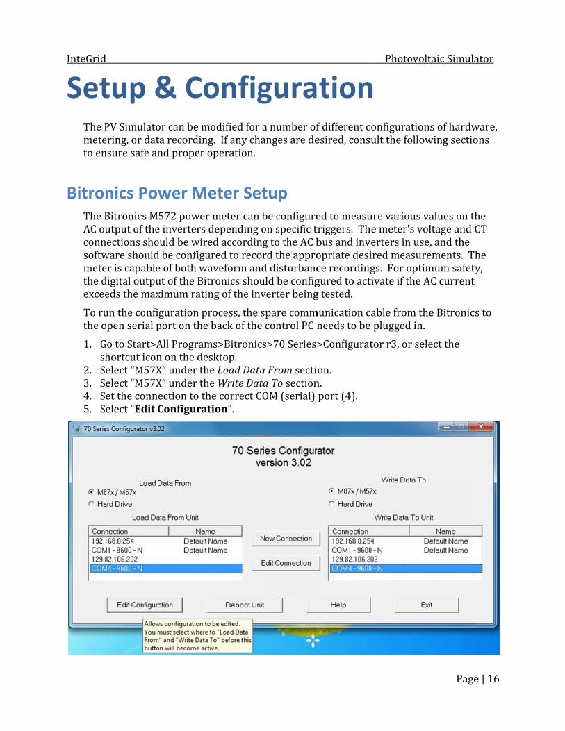
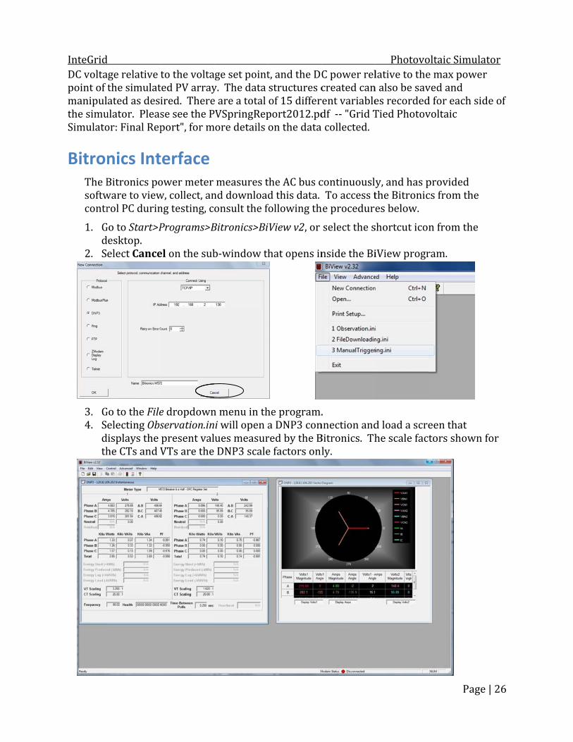
Set The Pmeteto en BitronThe BAC ouconnsoftwmetethe dexceeTo ruthe o1. Gsh2. S3. S4. S5. S
d tup &PV Simulatoering, or datnsure safe annics PowBitronics Mutput of thenections showare shoulder is capabledigital outpueds the maxun the confiopen serial pGo to Start>Ahortcut iconelect “M57Xelect “M57Xet the conneelect “Edit C
& Coor can be mota recordingnd proper ower Me572 power e inverters dould be wired be configure of both waut of the Bitrximum ratinguration prport on the bAll Programn on the desX” under theX” under theection to thConfigurat
onfig
odified for ag. If any chaoperation. eter Setmeter can bdepending oed accordingred to recoraveform andronics shoung of the invrocess, the sback of the ms>Bitronicssktop. e Load Datae Write Datae correct COion”.
gura
a number ofanges are detup be configureon specific tg to the AC brd the approd disturbanculd be configverter beingspare commcontrol PC ns>70 Series>a From sectia To sectionOM (serial)
tion
f different cesired, consed to measutriggers. Thbus and invopriate desice recordingured to actg tested. munication cneeds to be>Configuraton. n. port (4).
Photovon
configuratiosult the folloure various he meter's vverters in usired measurgs. For optitivate if the cable from the plugged intor r3, or se
oltaic Simula
Page
ons of hardwowing sectiovalues on tholtage and Cse, and the rements. Thimum safetyAC current he Bitronics. elect the
ator
e | 16
ware, ons he CT he y, s to

InteGrid
Onceconfi
Unde Unde
Unde Once all for the c ReferCT’s,
d e the Configuiguration op
er InstrumeSet CT raSet VT ra er Triggers aSet Wavesignal. TSet Digitathe triggeSet Waveer RecordinSelect dedesired chahanges to tar to the Bitrtriggering,
urator openptions on th
nt Transfortios to 100:atios to 1:1 fand Alarmseform and Dhis is the inal Output 1 er for the Bieform and Dg Modes>Disired valuesanges have bake effect. ronics M57x data collect
ns, the followhe left.
rmer>Ratios5 for the Flefor direct co>Recorder Disturbance put from thto go high witronics relaDisturbance isturbance s to record ibeen made, User Manuation, and me
wing screen
s: ex-Core AL-onnections wTriggers: Recorders the cDAQ digwhen currenay in the safRecorders t or Recordin each casehit the "OK
al for more easurement
n appears w
-101 currenwithout PTsto trigger ogital output.nt is greaterfety circuit.to trigger oding Modes>e.
K" button andetailed inst recording.
Photovowith the vari
nt transforms. n a Digital Ir than invern any other>Waveform
nd allow thestructions o.
oltaic Simula
Page
ous
mers. Input 1 “higrter max. Thr desired vam: e unit to rebon setting up
ator
e | 17
gh” his is lues. boot p

InteGrid
SummThe Alimitmustmust20 fo1. G2. Gth3. If
C5. U6. C7. UIn8. Uliindto9. Nu10. C11. E
d mit® DCAEHost Buss, regulationt be set to ent be on in oror instructioGo to Start>AGo to the Virhe shortcut f any change
OM1 of the Under Controlick the “conUnder the Conternal, the Under the Comits for eacnverters in uissipated aco the invertNow change nder the coClick the “coExit the VFP
C Power Virtual Fron mode, andnsure safe order to commons on turniAll Programrtual PC’s Sticon on thees are made
virtual macol Mode clicnnect” buttoonfigurationLocal/paneonfigurationch half of thuse. Add excross the prer. the Controlntrol of theonnect” buttP program, t
r Supplyont Panel sod control mooperating comunicate wng the powms>Windowart>All Proge virtual dese, click on th
chine. ck on VFP toon, , to con tab on the el to Externan tab, select e supply. Txtra power tre-load resisl Mode backe cDAQ. ton, , agathen log out
y Setupftware is usode on the Sonditions. Twith it. Referer supply os Virtual PCgrams>Advktop. he “Settings”
o use serial onnect to thright, selecal, and the UPVI Limits aThese numbto the powestors, or thek to User/Anain, to discont of and clos
p sed to set cuSummit® poThe 480V ACr to the Turn. C>Windowsvanced Ener” button in t
communicahe power suct Program SUser/Analogand set the ers depend er limit to ace supply manalog. Thisnnect fromse the Virtua
Photovourrent, voltaower supplyC feed to thrn-On Proce XP Mode. rgy>Summitthe Toolbarthe p“Unit“Bau“ComModpageSumSuppand pSumFronMan4ComContthe cLocacorreport.ation. upply.
Source. Set tg to Externapower, volton the Powccount for thay limit the ps places the the power sal XP windo
oltaic Simula
Page
age, and powy. These lime power supedure on pagt VFP, or selr and confirpower suppt Address”,ud Rate”, andmmunicatione”. Refer toe 4-26 of themit® DC Poply User Mapage 3-9 of mit Virtual nt Panel Useual for deta4. In the municationtrols sectionconnection tal and to theect COM (se. This shoulthe VFP to al tage and curwer Supply ahe power power availsupply backsupply. ow.
ator
e | 18
wer mits pply ge lect m ly’s d n o e wer nual the er ails. n n, set to e erial) ld be
rrent and lable k
InteGrid Photovoltaic Simulator
Page | 19
LabVIEW Program Setup There are two LabVIEW programs written to operate the DC supply. Both are available through shortcuts located on the control PC desktop. The first is a manual operator, which can be used to operate the supply as a constant source. It requires manual operation of all digital and analog controls, and should only be used for special testing by someone familiar with the system. It uses no information about the inverters or potentially simulated PV modules. More detailed information will not be provided here. The primary program is the PV Simulator LabVIEW program. It uses inverter and module data, predetermined irradiance values, and measured current and voltage values during the simulation to automatically operate the DC supply as though it were a real PV array. Listings of inverters, modules, and irradiance profiles already exist in the program, but additional information can be added if desired. Adding Inverters & PV Modules Inverter and PV module models that do not exist in the lists in the simulator program can be added manually. This is done by adding a row for each in the “Inverter&Module Data.xls” excel file. Navigate to C:\PV Simulator\Inverter&Module Data.xls and open the file. Click on the Inverter Data sheet and add a row containing all known data for the new inverter, entering data under the appropriate column header. Click on the Module Data sheet and add a row containing all known data for the new module, entering data under the appropriate column header. Save the file. When the LabVIEW PV Simulator program is reopened the lists will be updated.
Adding Irradiance Data Three options exist to simulate irradiance data from days not already saved on the control PC: Go to http://www.nrel.gov/midc/research/ and download desired irradiance csv files to C:\PV Simulator\Irradiance Data\RecordedProfiles. The files being used on the system are from the "SRRL 10Hz Direct Normal" section of the site. Use the IRModifierGUI.m Matlab program, located at C:\PV Simulator\Irradiance
Data\ . This program can modify existing recorded profiles, generate new simple profiles, select a shortened portion of a profile, or join two profiles together. It saves its output to the ModifiedIR.txt file. It is recommended this file be copied into the TestingProfiles folder and then renamed with an appropriate description.
Manually place a generated file in the RecordedProfiles or TestingProfiles folders. Be sure to conform to the format of the other existing text files. When the simulator program is reopened these new data files will be selectable.
InteGrid Photovoltaic Simulator
Page | 20
Operation Test Preparation/Turn-On Procedure The following procedure must be performed every time a simulation is conducted: 1. Determine whether or not either of the Preload Resistor Banks will be used. If so, open the appropriate DC disconnect box and close the 10A fuse located below the positive terminal on the output side of the disconnect. Also, be sure to turn on the
fan switch located to the side of the upper DC wireway. If the Preload Resistors will not be used, open the fuses and close the DC disconnect doors. 2. Open PV Simulator.vi located at C:\PV Simulator\PV Simulator.vi, or select the shortcut icon on the control PC desktop. Special Note: Since the simulator program uses some embedded Matlab scripts, the control PC must have access through the Ethernet hub to the CSU campus network in order to retrieve a license from the servers before the PV Simulator.vi will load. 3. Make sure all circuit breakers and disconnects are open. 4. The Load Bank or InteGrid AC grid connection should be turned on by an experienced operator in the lab following the InteGrid lock-out/tag-out procedures. 5. Hit the "Run Program" arrow icon in the LabVIEW PV Simulator program. This will activate the safety circuit relay so that the AC breakers in the system can be closed. 6. Remove lockouts and close the AC breakers and disconnects to the devices being attached to InteGrid for the simulation. 7. Close the DC disconnects and switches to the devices being used in the simulation. 8. Turn on the Summit® Power Supply by closing the main circuit breaker, then removing the lockout from, and then closing, the main fused disconnect. Once the DC supply has powered up, the status indicators on the LabVIEW interface should show that they are ready, and a simulation can begin. From this point, follow the directions for running a simulation with the PV Simulator program. See the descriptions of the interface and walkthrough in the following sections.

InteGrid
PV SiThe fand awill b
1. Stthte 2. Tthchpst 3. Tth 4. Stcao
d mulatofollowing inall the majobe given in t
tatus Indicahe "Simulatiest. The Record he Bitronicshance to regart of the "Otop both sidThe Programhe Emergentatus Indicaabinet, and r closed.
1
4 3 2
or LabVInstructions rr parts are dthe next sec
ators: Theseion CompleBitronics bs. It is recomgister the inOutput Datades of simul
m Stop and ncy Stop butators: Thesefrom the AC
5 6
IEW GUrefer to the described, tction.
e are digital ted" indicatbutton activmmended tonput. To reta" section ofator at onceEmergencytton will alse are digital C breakers.
8
7
UI PV Simulatthen a descr
inputs fromtors which lvates the digo hold this itrieve thesef this manuae. y Stop butto activate thinputs from They indic
tor.vi file. Ariptive walk
m the Summlight up whegital output in for a few e recordingsal. The othetons will endhe safety cirm the E-Stopate whethe
10
PhotovoA sample imak through fo
mit® DC suppen either sidto trigger aseconds so s, please seeer two butto
d the simularcuit. p button on r various co
9
1
oltaic Simula
Page
age is displaor a simulati
ply, except fde finishes aa recording the meter he the "Bitronons can staration. Pressthe main ontacts are o
11
ator
e | 21
ayed ion
for a on has a nics" rt or sing open

InteGrid Photovoltaic Simulator
Page | 22
5. A & B Tab control and Status window: Selecting one tab or the other will move between the windows for Side A or Side B of the simulator. Each side can run a simulation independently, and has identical controls and indicators. The large text "A" or "B" towards the top middle of the screen provides a quick reference of which tab is currently open. A tab does not have to remain open for the simulation to continue to run. The Status window provides the user some quick instructions during the start of a test, and an indicator of the state of the simulation during and after a test. 6. The upper four buttons are for starting, stopping, or resetting the sides of the simulator program independently. The 250 Ohm Preload Resistor? button changes DC current calculations for the measurements so that only the current flowing to the inverter is used in the voltage setpoint calculations. The default setting for this button is to be enabled. 7. Inverters and Modules: The two lists on the right show all the inverters and modules loaded into the simulator. The default inverter for Side A is the PVP3500, and the default inverter for Side B is the PVP30kW. After selections are made, the three boxes on the right display some of the important properties associated with the inverters, modules, and calculated array that will be used for the simulation. 8. Irradiance Graph: Clicking the folder icon will open a dialog box to select an irradiance profile text file to use for the simulation. The selected irradiance will be displayed on the graph after the file loads. As the simulation runs, a green tracking dot will display where the simulator is in the irradiance profile. The Start and End Time boxes can be used to select a shortened section of the loaded profile. The Elapsed Time box displays how much real time has passed since a simulation was started, which should be useful for determining if the five minute warm-up period of the inverters has elapsed. 9. PV Array I-V Curve: This graph displays the I-V curve for the calculated array at the present level of irradiance. The red dot shows the Maximum Power Point, and the green tracking dot displays the actual measured voltage and current. 10. Data Recording: These buttons control if, and at what rate, data from the simulator is collected. The default rate is 10 Hz. Selecting "Fast Data" changes the rate to 1 kHz. This information is only the DC behavior related to the supply. 11. Display of values: This graph displays some of the measured and calculated values for the simulator as it runs. The legend below the graph explains which values are displayed.

InteGrid
PV SiIn the fowhile th 1. P 2. C 3. P 4. Cp 5. E 6. S 7. S 8. Vat 9. Prechfl 10. Ptho 11. WdA 12. Tinin 13. Tpth
d mulatollowing dese program rerform steplick on the Lerform steplick on the sopulates thnter a Startelect the invelect the PVVerify the cattached invress the 25esistor bankhanges DC clowing to thress the Cohroughout tn the lengthWhen ready,ata. You ca
A&B button The test shounverters hasncoming volThe test will oint the "simhe supply sh
or Walktscription, sorelated stepps 1 throughLabVIEW “Rps 6 throughsmall foldere Irradiance
t Time and Everter to beV module to alculated arrerter limits0 Ohm Prek will be usecurrent calche inverter intinue buttthe test. Thh of the simu, Press the Rn press the if both sideuld begin ans a five minultage beforerun until it mulation cohould cease
throughome physicaps can be folh 4 of the TuRun” buttonh 8 of the Tur icon and see Graph. End Time fore tested usinbe emulateray size is co. eload Resisted. The defculations fors used in thton to calcuis should taulation beinRun button
Run buttons are ready nd the DC suute "warm-e it begins tohas gone thompleted" ine.
h al steps will llowed for eurn-On procn, , to starurn On procelect an Irra
r the test (inng the Invered using theorrect, i.e. ctor? buttonfault setting r the measuhe voltage seulate the I-V ake at least ang calculateto begin then independeto begin. upply will stup" period wo produce Ahrough the lndicator sho
only need teither Side Acedure. (Sert the progrcedure. (Se
adiance File
n units hh:mrter list. e Modules liscurrent and n so that it isg for this buturements soetpoint calccurves thata few seconed. e test and stently on eactart producwhere it chAC output. loaded irradould illumin
Photovoto be perforA or Side B oee page 20.) ram. (Step 5e page 20.) e from the pmm:ss). st. voltage leves illuminatetton is to beo that only thculations. t will be disnds to compltart measurch tab (A or
cing output. ecks for adediance profinate, and DC
oltaic Simula
Page
rmed once, of the simul5 of Turn-Onopup. This
els are withed if the pree enabled. The current played lete, depend
ring/recordB) or the St
Each of theequate file, at whichC output fro
ator
e | 23
lator. n)
hin load This ding
ding tart
e h om
InteGrid Photovoltaic Simulator
Page | 24
14. To end the simulation and download all the simulator data to the “MEASURED DATA” folder, press the Program Stop Output and Save Data button. The files will be generated and saved to the folder located at C:\PV Simulator\MEASURED DATA\Y-M-D HH:MM. A few of the buttons can be pressed at any time during a simulation: 1. Press the Record Bitronics button to record AC output data on the Bitronics meter. It is recommended to hold this in for a few seconds so the meter has a chance to register the input. Refer to the Setup & Configuration section to configure the triggered recording on a digital input on the Bitronics meter. 2. Press the Stop button or the Stop A&B button to turn the DC power supply output off. This pauses a simulation. The simulation can be resumed, but the inverters will go through another five-minute warm-up period. Enter the elapsed time into the "Reset Simulation Time" box while the Stop button is still latched in, release the Stop button, and then press the Run button to resume a simulation from the entered elapsed time. 3. Press the Emergency Stop button while a simulation is running to trip all the circuit breakers and isolate the system if an emergency situation develops. This completely stops a test, and no output data files are generated. 4. After manually stopping a simulation, press the Restart Program button to start over from the very beginning of a simulation. 5. Press the Record Fast Data button to record data at 1kHz instead of 10Hz.
System Turn-Off Procedure The following procedure should be performed when turning the system off after the test is complete and the LabVIEW program has stopped: 1. Ensure DC supply output is off, and allow the unit some time to run the cooling fans. 2. Open the 480V main circuit breaker and disconnect to the DC supply and lockout/tagout the disconnect. 3. Open the AC circuit breaker connections to InteGrid that were in use and lockout/tagout. 4. Open the remaining AC disconnects or DC disconnects that were closed for the test. 5. Open the main tie breaker to InteGrid in the switchgear downstairs, and open the main InteGrid breaker & lockout/tagout upstairs. 6. Turn off the preload resistor cooling fan switch.

InteGrid
Ou TherThe Das texmeteobse LabVI Wwill be sare creatsimulatotime of tthe num Infrom thedata. OnMatlab d
E(IOUT). the actuapower sumax powto the in
d tput
re are two pDC charactext files at ther system anrved or collIEW When the Praved in a foted, two foror were runthe test, the erical data cn order to ae C:\PV Simunce copied, odata structu
ach plot is vThe secondal output ofupply. The twer point ofverter. A se
t Datrimary soureristics are rhe end of a tnd must be rlected while
rogram Stolder entitler each side o. One file coinverter, PVcollected fronalyze this ulator\MATopen and rure and, if th
versus the sd graph is off the power third graph f the solar areparate figu
ta rces of outprecorded byest. The ACretrieved see a simulatiop Output ad with the dof the DC suontains the V modules, om the simudata, a Matl
TLAB folder aun the .m-filhe file is not
simulation tf DC voltagesupply, andis of DC powrray being sure, not show
put data for y the LabVIEC characterieparately. Ton is runninnd Save Dadate and timpply, depenproperties oand irradianulator. lab file, “Anand saved tle. This loadempty, crea
time in secoe (VOUT in bd V SET PT iwer (Pmp insimulated, awn here, als
analysis of EW PV Simustics are recThe data frong.
ata button ime of the tesnding on if oof the simulnce file usedalyzeDataDto the folderds the varioates the foll
onds. The toblue, V SET s the commn blue, POUand POUT isso shows th
Photovothe PV Simuulator progrcorded by thom the Bitro
s pressed, ast. Up to fouone or both lation, suchd, ect. The oDraft7.m”, mr containingous numericlowing plots
op plot showPT in red), wmanded voltaUT in red), ws the actual he absolute d
oltaic Simula
Page
ulator systeram and outhe Bitronicsonics can als
all the test dur separate sides of theh as the dateother contamust be copig the LabVIEcal data intos.
ws DC currewhere VOUage to the where Pmp ipower outpdeviation of
ator
e | 25
em. tput s so be
data files e e and ains ed EW o a
ent T is is the put f the
InteGrid
DC voltapoint of manipulthe simuSimulatoBitronThe Bsoftwcontr1. Gd2. S
3. G4. Sdth
d age relative tthe simulatated as desiulator. Pleasor: Final Repnics IntBitronics poware to viewrol PC durinGo to Start>Pesktop. elect Cance
Go to the Fileelecting Obsisplays the he CTs and V
to the voltated PV arrayired. Therese see the Pport", for mterface ower meter w, collect, anng testing, cPrograms>B
el on the sub
e dropdownservation.inpresent valVTs are the
ge set pointy. The data e are a total PVSpringRepore details measures tnd downloadonsult the f
Bitronics>Bib-window th
n menu in thi will open aues measurDNP3 scale
t, and the DCstructures cof 15 differport2012.pdon the data the AC bus cd this data. following thiView v2, or hat opens in
he program.a DNP3 conred by the Be factors onl
C power relcreated canrent variabledf -- "Grid T collected.continuousl To access the procedurselect the snside the Bi
. nnection andBitronics. Thly.
Photovolative to then also be saves recordedTied Photovy, and has pthe Bitronices below. shortcut iconiView progr
d load a screhe scale fact
oltaic Simula
Page
e max poweved and d for each sidvoltaic provided cs from the n from the ram.
een that tors shown
ator
e | 26
r de of
for
InteGrid
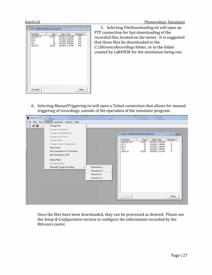
6. Str
OthB
d
electing Mariggering of
Once the filehe Setup & CBitronics me
anualTriggerf recordings
s have beenConfiguratioeter.
FTrecthaC:\cre
ring.ini will , outside of
n downloadeon section to
5. SelectinP connectiocorded files at these filesBitronicsReeated by Lab
open a Telnthe operati
ed, they cano configure
ng FileDownon for fast dlocated on s be downloecordings fobVIEW for t
net connection of the si
n be processthe informa
Photovonloading.iniownloadingthe meter. oaded to theolder, or to tthe simulati
tion that allomulator pro
sed as desiration record
oltaic Simula
Page
i will open ag of the It is suggese the folder ion being ru
ows for manogram.
red. Please sded by the
ator
e | 27
an sted un.
nual
see
InteGrid Photovoltaic Simulator
Page | 28
Appendix: Suggested Maintenance The filters on the front of the preload resistor box should be cleaned occasionally to ensure adequate air flow for cooling the resistors. The cooling fins of the heat sinks on top of the small inverters should also be cleaned occasionally. Information on Electrical Schematics & Matlab codes Please see the printed electrical schematics located in the pocket of the main control cabinet door. Current versions of the Matlab codes used in the simulator can be located on the control PC at C:\PV Simulator\MATLAB Glossary/Abbreviations AC …………… Alternating Current ADC ………… Analog-to-Digital Converter CBPB01 …… Circuit Breaker Panel Board 01 cDAQ ……….. Compact Data Acquisition CSU …………. Colorado State University csv …………… comma separated value CT ………….… current transformer DAC …………. Digital-to-Analog Converter DC …………… Direct Current DNP3 ………. Distributed Network Protocol EECL ……..… Engines and Energy Conversion Lab E-stop ……… Emergency Stop FTP ………….. File Transfer Protocol GUI …………... Graphical User Interface IR ……….…… Irradiance I-V …………… Current - Voltage kS/s ………… kilo-samples per second NC …………… Normally Closed N.I. …………... National Instruments NO …………... Normally Open PC …………… Personal Computer PTs …………. Potential Transformers PV ……….…… Photovoltaic SG3B ………... Switch Gear 3B UPS ………….. Uninterruptable Power Supply VFP ………….. Virtual Front Panel VTs ………….. Voltage Transformers

InteGrid Photovoltaic Simulator
Page | 29
User Notes: Use this area to write down any desired additional information: