Pvs
138
RE/PV-1 Pressure Vessels
-
Upload
bilalabdulmajeed -
Category
Documents
-
view
6 -
download
0
description
VESSEL
Transcript of Pvs

RE/PV-1
Pressure Vessels

RE/PV-2
Purpose
Introduction of the governing codes and basic considerations and concepts of pressure vessel design, fabrication, inspection, and modification.
Attendees will understand the basis for a vessel’s design conditions and will be able to determine the required thickness for internal pressure.
Attendees will also understand the purpose of common refinery pressure vessels and the function of their internals.
Finally, attendees will have a general understanding of vessel fabrication and repair or alteration.

RE/PV-3
Contents
Codes and StandardsPressure Vessel Shapes, Types, and UsesInternalsDesign ConditionsDesignPressure testingEvaluation, Repair, and Alteration

RE/PV-4
Codes and Standards

RE/PV-5
Codes and Standards
The purpose of this module is to identify the principle Codes and Standards that govern the design and fabrication of pressure vessels and to provide guidelines for finding the appropriate documents

RE/PV-6
Design Codes
Provide rules for the design of equipment adequate for design conditions determined by others.
Do not provide rules or guidance for the determination of design conditions, materials of construction or corrosion allowance.
Defined scope of most design codes includes new construction only, not revamps, repairs, or rerates.
Documents referenced by the Code are treated as part of the Code.

RE/PV-7
Design Codes
Code, in its entirety, and all of its provision must be used.
Laws and regulations in force at the site determine the Code (and perhaps the edition) that must be used and could limit use of referenced or auxiliary documents (e.g., Code Cases).
Calculations must be stamped by an experienced, licensed, professional engineer.
Fabrication should be performed in a shop with an ASME Code Stamp, signifying certification by ASME (and successful inspection by ASME).
RE/PV-8
Codes and Standards
ASME Section I “Rules for Construction of Power Boilers”– Used for steam generating equipment and
certain auxiliary equipment and piping
– Often used for power plants that cannot afford to be “down”; therefore, design a little more conservatism into them
– Uses factor of safety of 3.5 for tensile failure

RE/PV-9
Codes and Standards
ASME Section VIII Division 1 “Rules for Construction of Pressure Vessels”– Used for most unfired refinery equipment
– Uses factor of safety of 3.5 against tensile failure
– Required for external pressure and internal pressure greater than 15psig (1.05kg/cm2(g)). Limited to 3000 psig (210kg/cm2(g)) internal pressure (less as a practical matter)

RE/PV-10
Codes and Standards
ASME Section VIII Division 2 “Rules for Construction of Pressure Vessels – Alternative Rules”– Used for high pressure refinery equipment
– Uses factor of safety of 3 against tensile failure, resulting in thinner vessels (compared to Division 1)
– Not permitted in the creep range of materials
– Requires additional design analysis (e.g., local and thermal stress, fatigue) and quality control (e.g., full X-ray, stringent material requirements)
– Usually becomes economical if the shell thickness (per Division 1) exceeds 4 inches (100mm)
RE/PV-11
Codes and Standards
ASME Section II, Part D “Materials – Properties”– Lists allowable stresses for use with other Code
Sections– Provides other useful properties such as yield and
ultimate tensile strength– Properties listed as a function of temperature
ASME Section V “Non Destructive Examination”
ASME Section IX “Welding and Brazing Qualifications”

RE/PV-12
Codes and StandardsASME Code Cases and Interpretations
ASME Boiler and Pressure Vessel Code Cases and Interpretations– Code Cases are auxiliary to the Pressure
Vessel Code. If accepted by the local governing body they carry the legal weight and authority of the Code.
– Interpretations are committee responses to questions but carry no legal weight. They exist for many Sections of the Code.

RE/PV-13
Codes and Standards
TEMA (Tubular Exchanger Manufacturers Association)– Applies to shell and tube exchangers.– Provides some additional criteria, otherwise
references the pressure vessel Code.
Company Standards often supplement the Code, imposing additional requirements.

RE/PV-14
Codes and Standards
Other counties have similar Codes and Standards applicable to pressure vessel design. Europe has the new Pressure Equipment Directive (PED) as an “umbrella” procedure.
– Primarily addresses risk, safety (e.g., Essential Safety Requirements (ESR)), and traceability issues
– Requires approval by the Notified Body, 3rd Party Organization, or User Inspector
– ASME vessel (and piping design procedures meet the requirements, materials do not
– ASME is working towards compliance

RE/PV-15
Codes and Standards
Other, more specialized, Codes and Standards are mentioned in the following sections of this seminar.
An extensive list of applicable documents issued by API, ASME, PIP, and others is included as Attachment A to the handout.

RE/PV-16
Pressure Vessel Shapes, Types, and Uses

RE/PV-17
Vessel Types and Uses
In this Section, the primary shapes, types and uses of refinery pressure vessels will be described.
The attendee will be able to recognize common shapes and orientations of pressure vessels, and will understand the primary uses of pressure vessels in refineries.

RE/PV-18
Pressure Vessels
Pressure Vessel definition - A container in which an occurrence takes place at a different pressure than atmospheric.
In refineries, pressure vessels may up to 200 feet (60M) tall or 50 feet (15M) in diameter. They are designed for pressures up to 3000psig (210kg/cm2(g)) or temperatures of 1600ºF (870ºC).

RE/PV-19

RE/PV-20
Overall Geometry
The sphere is the most economical shape forpressure retention, but is rarely used– Used for some gas storage vessels, particularly
high pressureThe cylinder is the shape of nearly all refinery pressure vessels– Easy to fabricate– Constant cross section (eases internal
fabrication and installation, distribution and collection of process fluids, and process control)

RE/PV-21
RE/PV-22
Overall Geometry
Most vessels are oriented vertically unless there is a specific (process) reason to be placed horizontally (e.g., gravity separators)– Simplifies support– Minimizes “footprint”– Allows gravity to aid process
• Dense fluids fall, light fluids are displaced upwards
– Easier to modify volume by changing the length

RE/PV-23
Overall Geometry
Vessel dimensions (diameter and length) and orientation are controlled by process requirements (e.g., space velocity, fluid distribution, catalyst contact, residence time, tray design and spacing, etc.)
Cylinder length to inside diameter ratio of 3 or 4 is typically used– Provides good mix of inside volume, cross-section
area, and vessel cost (e.g., wall thickness)
Inside diameter and length dimensions are set to increments of 6 inches or 100 mm– Matches commonly available head sizes and “can”
lengths for the shell

RE/PV-24
Tangent and Weld Lines
Tangent Line– Point at which the head curvature begins
Weld Line– Point at which the head and shell are welded
together
The weld line is very rarely the same point as the tangent line. This moves the weld to a point where fit is easier (e.g., both sections are cylindrical) and away from any stress concentrations present at the geometrical joint.

RE/PV-25
Tangent and Weld LinesOverview

RE/PV-26
Common Refinery Pressure Vessels
Fractionators– Separates fluids by boiling/condensation point– Primary method of separation in a refinery– Requires energy (heat) input– Tall, vertical vessels
Separators/Receivers– Separate fluids of different densities (e.g., vapor and liquid)– Does not require energy input– May be horizontal or vertical
Surge Drums– Provide volume to absorb variations in fluid flow,
providing a smooth downstream fluid flow– Allows continued short term operation if feed is interrupted– May be horizontal or vertical

RE/PV-27
Common Refinery Pressure Vessels
Reactors– Contain chemical reactions that are the heart of the
process– Nearly always vertical– Contain a catalytic material (generally granular)– Most severe operating conditions in the process unit
Regenerators– Regenerate catalyst in circulating Catalyst Systems
Miscellaneous– Heat Exchangers– Pump casings

RE/PV-28
Common Head Styles
HemisphericalEllipticalConicalFlanged and DishedTorisphericalFlat
Hemispherical and 2:1 Elliptical are the most common.

RE/PV-29
Internals

RE/PV-30
Internals
This section describes common internals and their function.
The attendee will be able to recognize commonly encountered internals and understand their function.
RE/PV-31
Internals
Internals are normally used to control the flow of fluids within a pressure vessel. Proper distribution, collection, and mixing of fluids is critical to the performance of the process.
Other internals are used for auxiliary purposes, such as support of catalyst beds.

RE/PV-32
Fractionation
Rising vapor contacts with descending liquid.The vapor strips light components from the liquid.The liquid absorbs heavy components from the vapor.Internals maximize the vapor/liquid contact and distribute the vapor through the liquid.

RE/PV-33
All the liquid goesdown each downcomer
Downcomer Seal Area
Odd and even trays are identical but are rotated 180º from each other
Active Areaor Bubbling
Area
Downcomer Area
Fractionation Devices - Trays

RE/PV-34
Fractionation Devices
Trays– Sieve
• Simplest, most common style• 2 to 1 operating range
– Valve• Cost about 20% more than sieve tray• 5 to 1 operating range• Subject to plugging
– Bubble Cap• Cost may be 3 times valve tray• Good if no weeping is critical
– Cartridge (an assembly of several trays inserted as a unit into small diameter vessels
The number of trays is a process variable, determined by the boiling point differences, the number of products sought, and the purity required

RE/PV-35
Valves, Bubble Cap, Sieve

RE/PV-36

RE/PV-37
Tray Concerns
Flooding– Vapor velocity entrains too much liquid to tray above– Tray hydraulics and downcomer size do not allow all
of the liquid to flow to tray below• High tray pressure drop or downcomer exit loss• High downcomer velocity may entrain vapor
Weeping, i.e., loss of liquid through the vapor holesTurndown capacityCorrosion, debris, dislodged traysFouling/plugging of vapor openings

RE/PV-38
Fractionation Devices - Packing
Packing– Random (dumped)
• Raschig Rings• Pall rings• Raschig Super-Ring• IMPT (Koch-Glitsch)• Nutter Rings (Sulzer)
– Structured - Koch-Glitsch, Sulzer, Others.– Cost may be 5 times sieve tray– Pressure drop may be 1/5 that of sieve tray

RE/PV-39
Raschig ProductsPhotos From Raschig
Super-Ring Various Products

RE/PV-40
VIDEO

RE/PV-41
Separators
Commonly used for desalters, separators, receivers, coalesces, knockout drums, etc
Separates 2 or 3 fluids (vapor and liquid)
Separates by means of density – closer densities are more difficult to separate– Also depends upon droplet size, material
viscosity, and drag coefficient

RE/PV-42
Exercise
Why are separators used? Give two or three uses. What are some examples in a refinery?

RE/PV-43
Separators
Separates by means of one or more of the following methods– Momentum – Denser materials respond more
slowly to sudden changes flow of direction– Settling – Heavier materials settle to the
bottom, displacing lighter materials upwards– Coalescing – combines small droplets into
larger droplets to promote settling

RE/PV-44
Horizontal and Vertical Separators

RE/PV-45
Separators
Settling is governed by terminal velocity, i.e., how fast the dispersed material moves relative to the continuous phase material
Vessel is sized so that separation occurs before the continuous fluid leaves the vessel– Targeting separation of smaller droplets
increases the size of the vessel– Different fluids (e.g., vapor or liquid) may be
the continuous fluid in different areas

RE/PV-46
Types of VesselsVapor/Liquid Separator
CFBA
D
Tangent Length
M.R. M.R.
Min.Min.
I.D.
Min.
CL
Example:Overhead Receiver Liquid Out
Vapor Out
Inlet Distributor
150
RE/PV-47
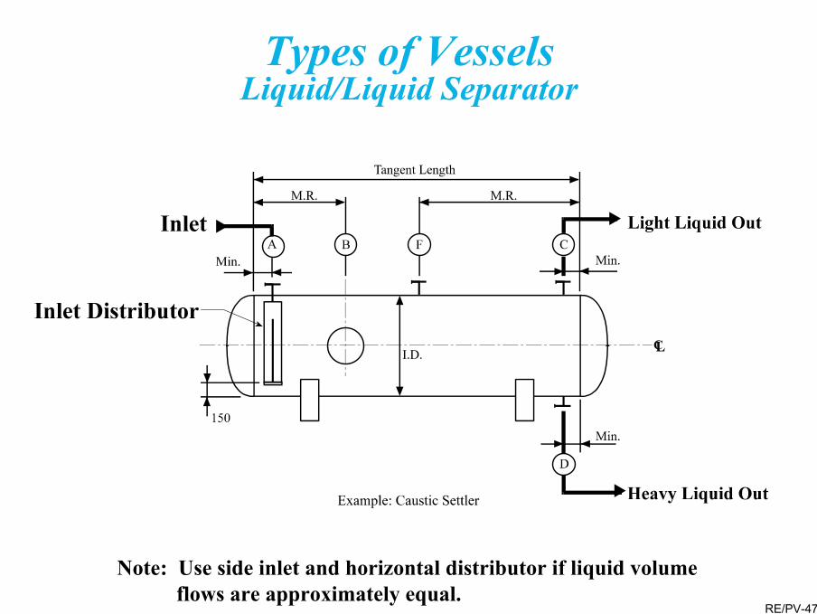
Note: Use side inlet and horizontal distributor if liquid volume flows are approximately equal.
Types of VesselsLiquid/Liquid Separator

RE/PV-48
Types of VesselsVapor/Liquid/Liquid Separator
Low Heavy Liquid Rate
EB
F
6"
Tangent Length
M.R.
Min.
I.D.
Min.
Example: HP Separator
D
Heavy Liquid Out
Light Liquid Out
FeedA
Vapor Out
Inlet Distributor
M.R.
CL
G
RE/PV-49
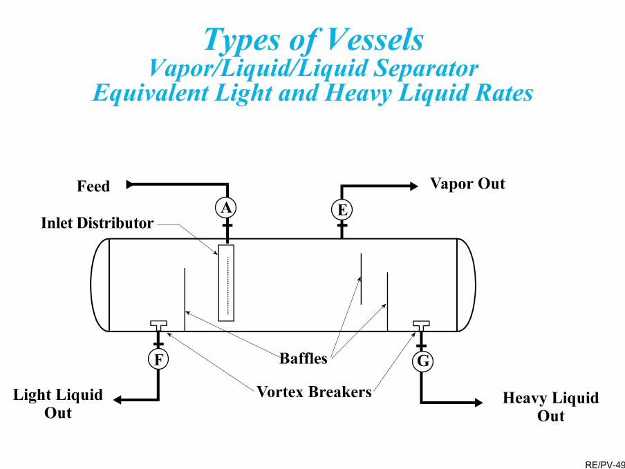
Types of VesselsVapor/Liquid/Liquid Separator
Equivalent Light and Heavy Liquid Rates
RE/PV-50
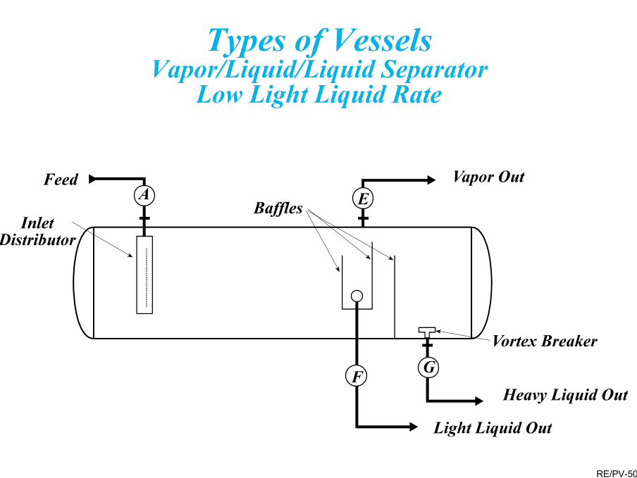
Types of VesselsVapor/Liquid/Liquid Separator
Low Light Liquid Rate

RE/PV-51
Separators
Separator Internals– Inlet distributors
• Provide momentum separation• Deposit each material in the portion of the
vessel where it is predominant (e.g., liquid on the bottom)
– Vortex breakers• Eliminate liquid vortexes at outlets• Vortex may reentrain/mix fluids
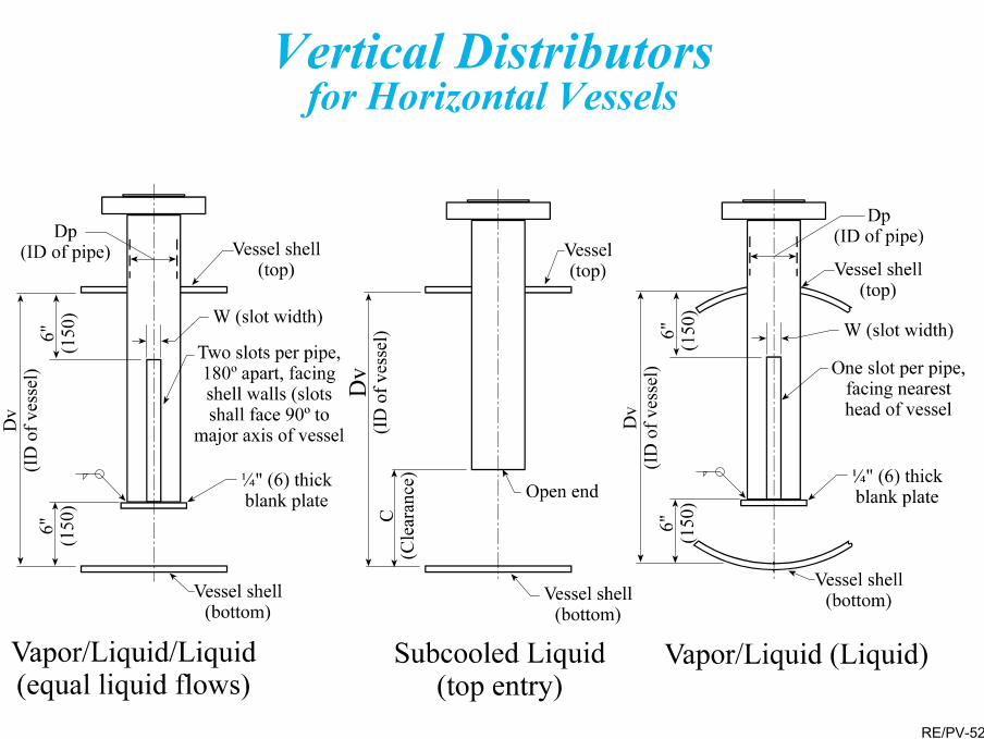
RE/PV-52
Vertical Distributorsfor Horizontal Vessels

RE/PV-53Raised Vortex Breaker Required for Two Liquid Phases
Vortex Breakers
4"
8" Dia.for 3"6" Dia.under 3"
3 - 3/4" x 1/4" BarsSpaced at 120º
3" and Under
2D
D
D
3"
D
Four WayBaffle
2D
D
4" Through 8" 10" and Over
2"
8"
4"2" H
4" Pipe
D
D Pipe
2D
D
2" H
D
D Pipe
2DFour Way
Baffle
3" H
D
3" and Under 4" Through 8" 10" and Over
H = as specified

RE/PV-54
Separators
Mist Eliminators– Used to “dry” vapor streams– Coalesce small liquid droplets together– Promotes gravity separation of very small droplets– Creates a complex, labyrinth, path forcing droplets
to collide with each other or parts of the device– Types
• Vanes• Centrifugal Elements (e.g., cyclones), separate
by momentum differences• Filters

RE/PV-55
Vane Mist Eliminators

RE/PV-56
Centrifugal Elements

RE/PV-57
Separators
– Types• Electrostatic precipitators (separate via attraction
to/repulsion from electrically charged plates• Mesh blankets
– The most common type.– Consist of a ‘maze’ of small, intertwined wires.
Usually 6-12 inches (150-300mm) thick in the direction of flow.
– High efficiency for a range of velocities, processes, droplet sizes, fluids. Wide turndown (or turnup) flexibility.

RE/PV-58
Separators
– Mesh Blankets• Low cost• Easily installed or replaced (even as a retrofit• Low ∆P and operating costs• Plugs easily, not suitable for fouling services

RE/PV-59
Typical Horizontal Installationof a Sectional Mesh Blanket

RE/PV-60
Surge Drums
Surge drums are “wide spots in the line”Sized to provide a desired residence, or retention, time– Required volume is a function of the flow rate– Set by process or operation considerations– Usually between 5 and 30 minutes– Has few internals– May be a dedicated vessel or part of another
vessel, like a separator or fractionator

RE/PV-61
Reactors
Flow may be axial or radialRequired internals may be complexContain catalyst to promote the desired reaction– Internals contain and support the catalyst– Catalyst may have an inert material below (and
above) to help contain the small diameter catalyst– In circulating catalyst systems the internals
control the catalyst flow

RE/PV-62
Reactors
Internals evenly distribute, collect, and mix flow. Maldistribution has severe process consequences.Due to the severe design/operating conditions the internals ore often made of a high alloy.Damage to internals affects process performance and may allow catalyst to escape and damage downstream equipment.

RE/PV-63
Downflow Reactor
Inlet Distributor
V/L Tray
19 MM Balls
6 MM Balls
Catalyst
3 MM Balls
19 MM Balls6 MM Balls
Tray Manway
Unloading Sleeve
Outlet Basket

RE/PV-64
Radial Flow Reactor
Catalyst Bed Coverplate
Scallop Shield
Centerpipe Shroud
Outer Screen
Catalyst Bed (Concentrically Loadedaround Centerpipe)
Centerpipe)

RE/PV-65
Design Conditions

RE/PV-66
Design Conditions
In this section the pressure and temperature conditions used for pressure vessel design will be defined and the means of determining them outlined
The attendees will be able to understand the basis for and meaning of the design conditions specified for a pressure vessels

RE/PV-67
Process Design ConsiderationsInternal Pressure
Maximum Operating– Highest operating pressure foreseen for all
applicable cases (normal, turndown, startup shutdown)
Design Pressure– Maximum operating pressure plus a safety
margin (a margin is not mandated by the Code)

RE/PV-68
Process Design ConsiderationsInternal Pressure
Internal Design Pressure – Typically the greater of
• 110 percent of the maximum operating pressure• maximum operating pressure plus 15 to 25 psi
(1.05 to 1.75 kg/cm2)• A minimum value set by the owner
– Must accommodate the relief valve set point and reclosure pressure (usually about percent below the set point)
– More responsive relief valves (e.g., pilot operated valves) may permit a smaller margin, e.g., design for 105 percent of the operating pressure

RE/PV-69
Process Design ConditionsExchanger Design Pressure
To avoid the need for an additional relief valve, the low pressure side may be designed for 10/13 of the high pressure side design pressure

RE/PV-70
Vacuum (external pressure) conditions are specified for– Equipment that operates under vacuum
(including startup and shutdown)– Equipment is subject to vacuum during drainage– Where loss of reboiler or other heat to a gas with
a resultant cooling, even condensation, can result in a vacuum
Design may be for full vacuum or a specified partial vacuumDesign of all vessels for a minimum vacuum (e.g., 2.5psig (0.175 kg/cm2(g)) is common
Process Design ConditionsVacuum Design

RE/PV-71

RE/PV-72
Process Design Considerations
Design pressure is defined to be at the top of the vessel in its operating position
Mechanical design conditions at the bottom should consider:– Liquid head– Upflow or downflow pressure drop– Hydrostatic test conditions

RE/PV-73
Process Design ConditionsDesign Temperature
Normal Operating– Highest temperature expected during the
equipment’s operating cycle, including start and end of run.
Design Temperature– Normal operating temperature plus a margin (a
margin is not mandated by the Code)– May set a minimum value (e.g., based on steamout)
If operation is cryogenic (cold), the margin is a minus value. Alternative margins may be considered where the metallurgy is affected

RE/PV-74
Design Temperature
Cold Wall Design– Internally insulated vessels allow lower shell design
temperature and possibly a lower and less expensive metallurgy
Flange Classes– Watch the effect on the flange class when setting the
design temperatureConsider the effect of elevated design temperature on the allowable design stress. Due to creep considerations, the allowable stress can drop rapidly at elevated temperatures.

RE/PV-75
Specified Design Conditions
The specified design conditions are those resulting in the most severe head/shell requirements– Generally the greatest temperature and greatest
pressureIf the greatest temperature and pressure do not act simultaneously, the governing case may not include either or bothDifferent portions of the equipment may have different design conditions– Consider need to accommodate pressure testing

RE/PV-76
Low Temperature Requirements
At low temperatures, many materials may become brittle– ASME Code contains additional requirements
for these materials depending upon the applicable MDMT
MDMT stands for Minimum Design Metal Temperature– Is the lowest mean temperature of the metal (not
the internal fluid) considering many factors, including operating temperature, low ambient temperature, and auto refrigeration

RE/PV-77
Low Temperature Requirements
Application of additional requirements (e.g., impact testing) depends upon the material, MDMT, and thickness
Figure UCS-66 of ASME Section VIII Division 1 is used to determine if Charpy V-notch testing is required
Low temperature considerations (the MDMT) may lead to a change in the metallurgy.

RE/PV-78
Name Plate
Name plates must be prominently affixed to all vessels and contain the information called for by the Code in Section UG-116. See the following slide.
The maximum allowable working pressure is the maximum permissible pressure at the top of the vessel. It’s based on the actual metal thickness minus the corrosion allowance. The design pressure is frequently (and conservatively) used.
The Code Stamp indicates Code used and signifies that the fabricator abides by ASME guidelines and has passed their inspection.

RE/PV-79
W (if arc or gas welded)RT (if Radio graphed)
HT (if Postweld heat treated)
Name of Manufacturer
psi at °FMax. Allowable Working Pressure
Min. Design Metal Temperature
Manufacturer’s Serial Number
Year Built
°F at psi
Name Plate

RE/PV-80
Design

RE/PV-81
Design
This section introduces the basic methods and considerations for determination of pressure vessel shell and head thicknesses. The means of accommodating openings (nozzles) is also presented.
Attendees will be able to design simple vessels for internal pressure and understand some of the other factors influencing the shell thickness. They will also understand comment methods of providing nozzle reinforcement.

RE/PV-82
Design
Loadings causing stress in the shell– Internal or external pressure– Wind and seismic– Vessel and contents (internals, catalyst, fluids) weight– Attached equipment and piping– Thermal gradients– Impact– Residual stresses– Local stress concentrations due to discontinuities– Cyclic loads (pressure or thermal)
This following discussion focuses on internal pressure, and touches on external pressure and wind/seismic concerns

RE/PV-83
Stress Analysis of Pressure Vessels
Derives the basic formulas for shell stress from internal pressure
Presents the ASME Code pressure design equations
Vessel design calculations must be performed by an experience, licensed, professional engineer

RE/PV-84
Stress Analysis of Pressure Vessels
Thicknesses determined from the presented methods do not include the corrosion allowance. The final thickness will be greater to include the corrosion allowance and to round to the next available plate thickness.
A glossary of terms is included in Appendix B.

RE/PV-85
ASME Code Design ThicknessEquations for Shells
Section VIII, Division 1
Cylindrical Shells– Circumferential stress (longitudinal joints)
t PRSE P
=− 0 6.
Limits Rt 12
P 0.385SE
≤
≤

RE/PV-86
ASME Code Design Thickness Equations for Shells
– Longitudinal Stress (circumferential joints)
– For circumferential stress (longitudinal joints), based on the outside radius
t PRSE P
=+2 0 4.
Limits Rt 12
P 1.25SE
≤
≤
t PRSE P
O=+ 0 4.

RE/PV-87
Common Head Styles
HemisphericalEllipticalConicalFlanged and DishedTorisphericalFlat (rare due to its large thickness for all but very small vessels)
Hemispherical and 2:1 elliptical are by far the most common styles

RE/PV-88
Hemispherical– Optimal pressure containing shape– Half as thick as the shell– No sharp radius bends (e.g. knuckles) or stress
concentration points– Joint with the shell is more complex– More difficult to form or fabricate, fewer
potential vendors– Suitable for thick shells (> 2 inches (50mm))
(from a cost viewpoint)
Hemisphericalversus 2:1 Elliptical Heads
RE/PV-89
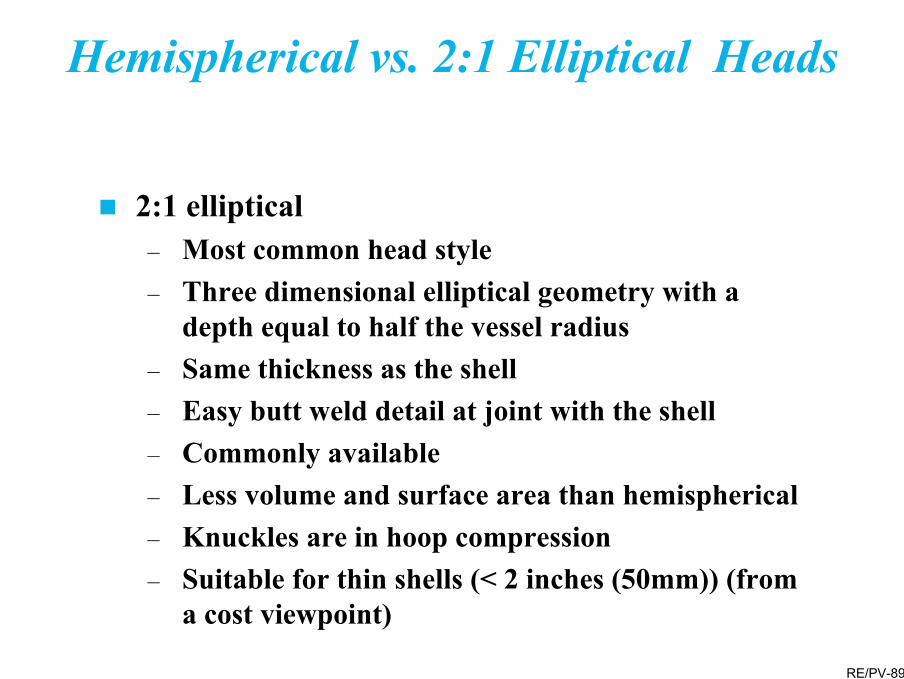
Hemispherical vs. 2:1 Elliptical Heads
2:1 elliptical– Most common head style– Three dimensional elliptical geometry with a
depth equal to half the vessel radius– Same thickness as the shell– Easy butt weld detail at joint with the shell– Commonly available– Less volume and surface area than hemispherical– Knuckles are in hoop compression– Suitable for thin shells (< 2 inches (50mm)) (from
a cost viewpoint)

RE/PV-90
ASME Code Design Thickness Equations for Shells and Heads
Spherical Shells
Spherical shells based upon the outside radius
t PRSE P
=−2 0 2.
Limits t 0.356R P 0.665SE
≤≤
t PRSE P
O=+2 0 8.
Note that this equation is similar to the equation used for piping

RE/PV-91
Pressure Vessel Heads
t
Pressure Vessel Heads− Ellipsoidal
where
For a 2:1 ellipsoidal head K=1
t PDKSE P
=−2 0 2.
or P = 2SEtKD + 0.2t
K Dh
= +
16
22
2
h
D

RE/PV-92
ASME Code Design Thickness Equations for Heads
Pressure Vessel Heads– Conical (without transition knuckle)
( )
( )
t PDSE P
t PDSE P
O
=−
=+
2 0 6
2 0 4
cos .
cos .
α
α
Limits:Half Apex Angle, α<30°P ≤ 1.25SE
D
rα

RE/PV-93
ASME Code Design Thickness Equations for Heads
Pressure Vessel Heads– Toriconical heads (conical portion)
( )t PD
SE Pc = −2 0 6cos .αLimits r > 0.06DO
r > 3tkmandatory if α>30°
+=
=
−=
rLM
DiL
PSEPLMtk
341
cos2
2.02
α
DL
Di
r
tK
tc
α
α
– Knuckle portion

RE/PV-94
Pressure Vessel Heads
Pressure Vessel Heads− Torispherical
where
t PLMSE P
=−2 0 2.
or P = 2SEtLM + 0.2t
M Lr
= +
14
3 for the typical case where
r=0.06L and L=skirt OD,
t PLSE P
=−
0 8850 1
..
LD
r
t

RE/PV-95
Welds shall be examined by full or spot radiography– Full — Radiography of the entire length of the
weld joint– Spot — Radiographic examination of one spot in
each 50 feet (15M) or fraction thereof for each welder, weld method, or type of joint
Ultrasonic examination may be substituted for radiography for the final closure seam if it is not possible to obtain interpretable radiographs
Weld Examination

RE/PV-96
Efficiency of Welded Joints (E)(Excerpt from ASME Code Table UW-12)
Degree of RadiographicExamination
No. Type of Joint Full Spot None
1 Double-welded butt joint or single-welded butt joint with backing stripwhich does not remain in place
1.00 0.85 0.70
2 Single-welded butt joint with backingstrip which remains in place
0.90 0.80 0.65
3 Single-welded butt joint without useof backing strip
– – 0.60
Type 1 joints are generally required for refinery vessels
Hemispherical and ellipsoidal heads are either seamless or 100% radiographed and use a joint efficiency of 1

RE/PV-97
Allowable Stress Table
•Reproduced from ASME Section II, Part D.
•“P-nos” and “Group Nos” are used to combine similar materials for the purpose of specifying postweld heat treatment and welding requirements.

RE/PV-98
•Reproduced from ASME Section II, Part D.
•NP = not permitted.
The referenced notes provide additional requirements, cautions, limitations, or comments.
Allowable Stress Table
(continued)

RE/PV-99
•Reproduced from ASME Section II, Part D.
•Values in italics are governed by time dependent (creep) effects, and may deform over time.
•At elevated temperatures, allowable stresses decline rapidly. A small temperature change may lead to a large thickness change.
Allowable Stress Table(continued)

RE/PV-100
Exercise
What is the approximate required thickness of the following cylindrical vessel?– Material = SA 516, Grade 65
– Inside diameter = 10 feet
– Design temperature = 750 ºF
– Design pressure = 500psi
– Joint efficiency 0.85 (spot radiography)

RE/PV-101
Nozzle Details
Although nearly any orientation is possible, for ease of design and reinforcement, nozzles should be perpendicular to the shellNozzles (and reinforcement) in heads are normally parallel to the vessel axis. To comply with the above point they are normally located within the center 80% of the head diameterAlthough not prohibited by codes, avoid locating nozzles in or near vessel weld seams– Nozzle and any reinforcement will interfere with
the ability to inspect and NDE the vessel weld

RE/PV-102
Nozzle Details
Nozzle to shell welds are difficult to examine, especially to radiograph, because of the difficulty in accessing welds between two components at a right angle and the interference in the readings caused by the geometrical changes

RE/PV-103
Vessel FabricationNozzles
C. Built-up Nozzles D. Integrally Reinforced Nozzles
A. Pipe Couplings - Generally Avoided B. Forged Steel Nozzles

RE/PV-104
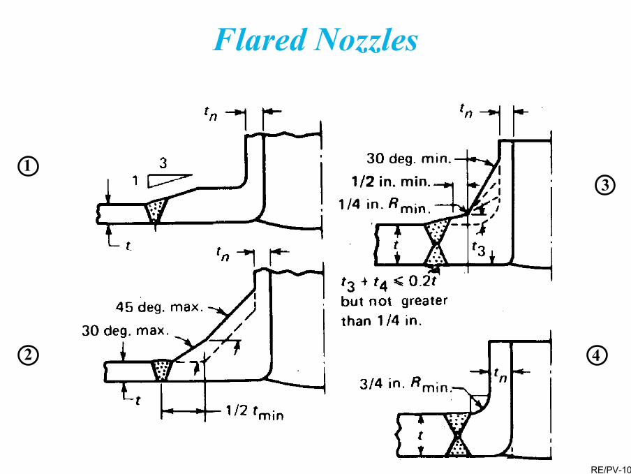
Flared Nozzles
For high pressure, high temperature, cyclic, and other critical services, flared nozzles as shown on the following slide are often used. They– Separate the mechanical and thermal stress zones– Remove mechanical stresses from the heat affected
zone at the weld– Improve welding access and permit the weld to be
radiographed– “Smooth” the stress transition from the heavy nozzle
forging to the shell– Are, however, expensive
RE/PV-105
1
2
3
4
Flared Nozzles

RE/PV-106
Nozzle opening reduces the shell strength
Replace cross-sectional area of metal removed
Available reinforcement includes excess shell and nozzle thickness
Limits of effective reinforcement defined by the code
Nozzle Reinforcement

RE/PV-107
Nozzle Reinforcement
Additional reinforcement may be provided by surface pads, insert plates, thickened full or partial shell courses, or thickened nozzle necks (integrally reinforced)

RE/PV-108
Section A-A
Vent hole

RE/PV-109
Nomenclature and Formulasfor Reinforced Openings
rn
2.5t or 2.5tn + teUse Smaller Value
2.5t or 2.5tn Use Smaller Value
t c
h
tn
trn
tr
d
te
d or Rn + tn + tuse larger value
d or Rn + tn + t
Reinforcement zone
Dp

RE/PV-110
A = Reinforcement area required
A1 = Area available in shell
A2 = Area available in outer nozzle
A3 = Area available in inner nozzle
A4 = Area available in welds
A5 = Area available in pad (if required)
A1 + A2 + A3 + A4 + A5 (if required) ≥ A
Opening Reinforcement
(Special Code rules apply for closely spaced nozzles)

RE/PV-111
Computer Programs
Vessel designs are calculation intensive, and require attending to many details and Code requirements. Computer programs ease the “number crunching” burden on the engineer and accommodate Code requirements. Two programs are– COMPRESS– VCESage
Specialized finite element programs are used for detailed local analysis

RE/PV-112
Pressure Testing

RE/PV-113
Pressure Testing
In this section the basic Code requirements for pressure testing are outlined.
The attendee will understand the methods of pressure testing, and their strengths and weaknesses, and will also be able to determine the required test pressure for given design conditions.

RE/PV-114
Pressure Testing
Pressure testing is required by the ASME Code
Testing confirms the vessel integrity by stressing it to a level greater than it will see in operation
Testing to be performed after all fabrication, welding, and heat treatment is completed– Testing should occur prior to any painting or priming
Testing to be observed by the authorized inspector

RE/PV-115
Pressure Testing
Test pressure may be based upon either– The design pressure (this is the normal method)– MAWP of the full, corroded or uncorroded
thickness
Two types of pressure are accepted by the Code:– Hydrostatic– Pneumatic

RE/PV-116
Hydrostatic Pressure Testing
Vessel is filled with water and pressured to the required valueSection VIII Division 1 minimum required test pressure at all locations = 1.3 • DP • SC/SH
Use the lowest SC/SH ratio (This factor increases the level of stress during test to the relative level seen in operation)Recommended test temperature is 30ºF (17ºC) over MDMT– Temperature is of the metal, not the test fluid– Addresses the potential for brittle fracture

RE/PV-117
Hydrostatic Pressure Testing
Test is safer due to incompressibility of water (or other fluid)– Little energy is stored in the test fluid under
pressureEasy to see and detect leaks; large water molecule may not reveal some small openingsMay add a dye or luminescent material to see leaks

RE/PV-118
Hydrostatic Pressure Testing
Adequate supply of suitable water may be difficult to obtain– For example, where stainless steel is present,
chlorides are limited to 50ppm
Some environments and internals (e.g. refractory) may make hydrostatic testing undesirable

RE/PV-119
Pneumatic Pressure Testing
Test pressure is provided by compressing air or another gasSection VIII Division 1 minimum required test pressure at any point = 1.1 • DP • SC/SH – As with hydrostatic testing, pressure may be
based upon the design pressure or the full corroded or uncorroded thickness
– Use the lowest SC/SH ratioMetal test temperature must be at least 30°F (17ºC) over the MDMT

RE/PV-120
Pneumatic Pressure Testing
Very dangerous due to stored energy in the compressed gas
Heat of compression, and subsequent cooling, may mean a loss of test pressure
Existence of a leak may be detected by a loss of (i.e. difficulty maintaining) internal pressure

RE/PV-121
Pneumatic Pressure Testing
May be difficult to see leak location—colored smoke sometimes added
No extra weight or hydrostatic pressure to consider
Does not damage refractory or impact the process

RE/PV-122

RE/PV-123
Exercise
What is the required hydrotest pressure for the following vessel?– Material = ASME SA 516 Grade 65– Design Pressure = 500psig– Design Temperature = 800ºF

RE/PV-124
Evaluation, Repair, and Alteration
RE/PV-125
Evaluation, Repair, and Alteration
This section introduces the concepts, common means, and Codes applicable to repairs, alterations, and the evaluation of damage to pressure vessels.
The attendee will develop an understanding of the requirements applicable to repairs and alterations and will be aware of the means of evaluating pressure vessels for continued service.

RE/PV-126
Evaluation
If damage (e.g., corrosion, thinning, cracks, bulges) is detected or metallurgical damage is suspected (e.g., cyclic or creep range operation), an evaluation for continued service may be required
Some damage may not require repair– Isolated pitting corrosion– Local thin areas if
• It is shallower than the corrosion allowance• There are no cracks, sharp corners or other stress
raisers (e.g., it’s not near a nozzle)– Thin areas deeper than the corrosion allowance may not
require repair if there are no cracks, sharp corners or stress raisers

RE/PV-127
Evaluation
Significant damage requires repair or, alternatively, a fitness for service (FFS) evaluation
– The evaluation may determine that repair or replacement is not required, a cost and downtime savings
Consider a formal fitness for service evaluation, especially if the vessel
– operated in the creep range– is deformed– has significant corrosion damage– experienced operational upsets including overpressure or
overheating– was subjected to cyclic loading– has been damaged (e.g. cracks) or deformed (e.g. bulges)

RE/PV-128
Evaluation
API 579 “Fitness for Service”, provides a basis for evaluation of– Brittle fracture (Section 3)– General metal loss (Section 4)– Local metal loss (Section 5)– Pitting corrosion (Section 6)– Blisters and laminations (Section 7)– Weld misalignment and shell distortion (Section 8)– Crack-like flaws (Section 9)– Creep range operation (Section 10)– Fire damage (Section 11)
API 579 considers three levels of evaluation– Level 1 – Uses simple, conservative criteria with a minimum of inspection
and component date. Performed by plant inspector or engineer.– Level 2 – uses the same input as level 1, but requires a more detailed
analysis. Performed by plant engineer of FFS expert.– Level 3 – A detailed, precise, evaluation, requiring detailed inspection
and component data. Performed by an FFS specialist.

RE/PV-129
Evaluation
FOS calculations and their interpretation are performed by specialists using software tools such as PREFIS.
For service in the creep range, a remaining life evaluation is necessary as a minimum. The evaluation is performed by a specialist using OMEGA. The older Larsen-Miller life fraction approach may also be sufficient in some situations.
RE/PV-130
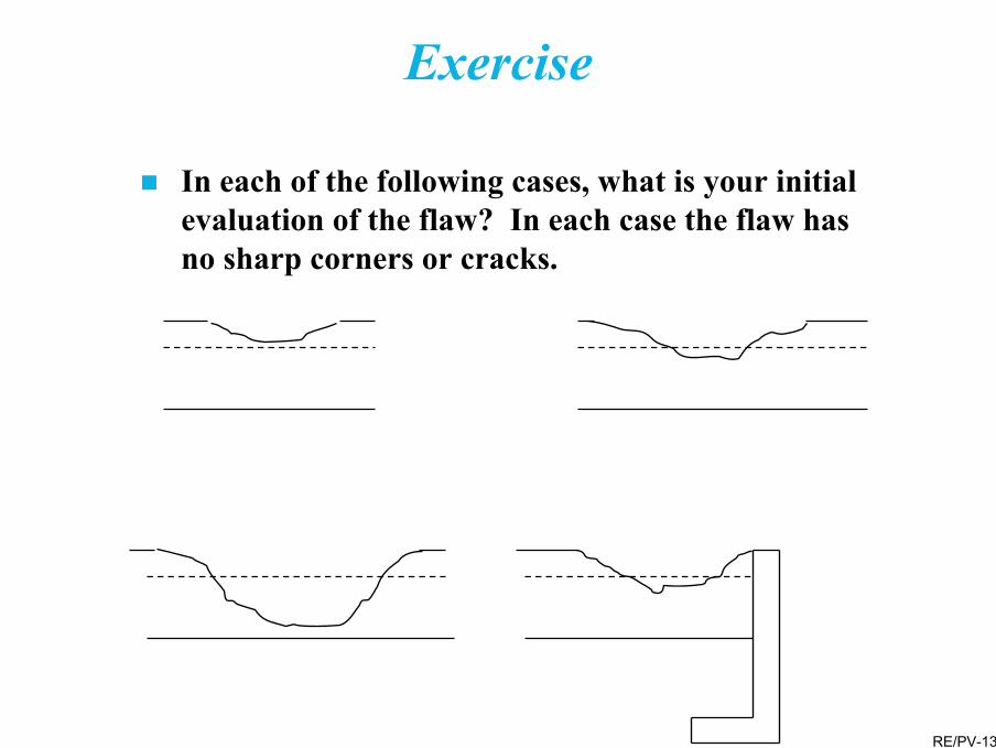
Exercise
In each of the following cases, what is your initial evaluation of the flaw? In each case the flaw has no sharp corners or cracks.

RE/PV-131
Scope of the familiar design codes covers new construction only– For repairs and alterations (revamps), other documents
governAs with codes for new construction, the applicable document depends upon local laws and regulationsTwo common documents are:– NB23 - National Board Inspection Code– API 510 - Pressure Vessel Inspection Code, Maintenance,
Inspection, Rating, Repair, and Alteration
Repairs and Alterations
RE/PV-132
Determine if vessel changes (including new design conditions) qualify as a repair or an alteration– Use the applicable Code, e.g., NB-23
• Repairs are restoration to original condition using original fabrication methods
• Alterations are changes in the pressure containing shell
– Requirements applicable to alterations are more stringent than for a repair
Repairs and Alterations

RE/PV-133
Repairs and Alterations
All modifications must be designed and performed in accordance with the governing Codes.Design should be performed by an experienced, licensed, professional engineer.All work to be observed and approved by the Authorized Inspector.Vessel is registered with, for example, the National Board. Complete National Board form R-1 for repairs and R-2 for alterations (see Appendix D).

RE/PV-134
Repairs and Alterations
Rerates, i.e., evaluation for more severe operation condition(s) are a special form of alteration– Suitability for service is determined per the original code
of construction.– Suitability of the materials for the intended atmosphere
must be checked, even if it has not changed.– Thoroughly inspect the vessel by both visually and
nondestructive means.– Perform a complete metallurgical evaluation to determine
the present metallurgical condition if damage is suspected (e.g., creep, fatigue, embrittlement, etc). Removal and testing of samples may be necessary.
– Use of the new (often greater) allowable stresses may be permitted if• The vessel was built after 1968• Impact test (Charpy V-notch) data is available

RE/PV-135
Repairs and Alterations
Repair methods include– Complete removal of shallow cracks, leaving a
thin area if the remaining thickness is sufficient. Contour all surfaces and junctions.
– Local thin areas and areas where deeper cracks were removed may be restored by weld buildup. PWHT may be necessary.
– Replace shell sections.• Corners to be contoured• Remaining shell to be supported and stable
during replacement• PWHT may be required
– Other repair methods (e.g., overlay plates) as described in the Piping and Valve seminar.

RE/PV-136
Repairs and Alterations
Proper fabrication methods must be used for the alteration, considering that the vessel has been in service– More care may be needed to prevent damage (e.g.
maintenance of proper pre, during, and post-weld heat temperatures, sequence of welding, dehydrogenization, existence of coke)
Thoroughly inspect and possibly test the modifications
If the vessel is relocated, or the length/diameter is increased, review wind and earthquake

RE/PV-137
FCC Repair
• Replacement of FCC cyclones, with the vessel top head, may qualify as a repair
• Cut and reweld to be in the cylindrical portion to ease fit up

RE/PV-138
Questions