PVQ Piston Pumps - SEVECO · PVQ piston pumps are in-line, variable displacement units and are...
68
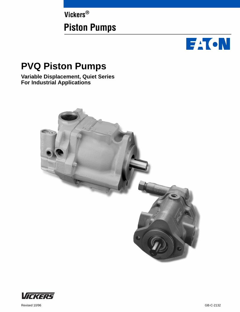
GB-C-2132 Revised 10/96 PVQ Piston Pumps Variable Displacement, Quiet Series For Industrial Applications Vickers ® Piston Pumps
Transcript of PVQ Piston Pumps - SEVECO · PVQ piston pumps are in-line, variable displacement units and are...
GB-C-2132Revised 10/96
PVQ Piston PumpsVariable Displacement, Quiet SeriesFor Industrial Applications
Vickers®
Piston Pumps
Vickers, Incorporated 1997All Rights Reserved
Introduction
PVQ piston pumps are in-line, variabledisplacement units and are available innine sizes. Displacement is varied bymeans of pressure and/or flowcompensator controls. An impressiveassortment of control options offersmaximum operating flexibility.
PVQs operate at quietness levels thatmeet today’s demanding industrialconditions. The sound level of each unitapproaches or is below that of theelectric motor driving it. Sound isreduced by a patented timingarrangement that also produces lowpressure “pulses” in the outlet flow. This
leads to reduced tendencies for noise insystems using PVQs.
The PVQ series is capable of operatingwith many types of hydraulic fluid.Water-content and phosphate esterfluids can be accommodated, in additionto the typical petroleum based andsynthetic fluids.
Many PVQ pumps are available in athru-drive configuration to accommodatea multitude of application and installationrequirements. Thru-drive models can becoupled to various types and sizes offixed and variable displacement pumps,resulting in a compact and versatile
package. Such a package offers lowerinstalled cost by reducing the installationsize and by requiring only one mountingpad on the prime mover.
Quiet PVQs have excellent operatingcharacteristics, and the pumps’ manycontrol and mounting options allowchoosing the optimum model for anyapplication. Additionally, PVQs possessthe same durability and long lifecharacteristics expected of the bestindustrial products in today’smarketplace. For over 75 years, theVickers name has been synonymouswith long trouble-free service.
1
Contents
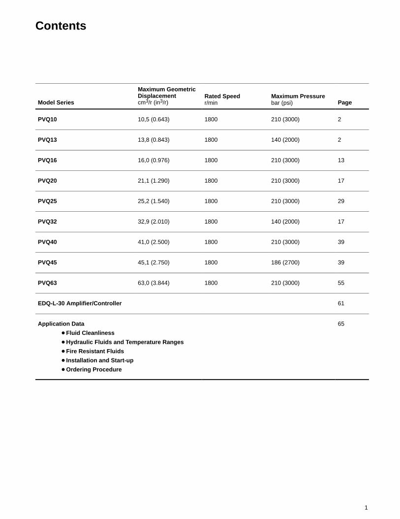
Model Series
Maximum GeometricDisplacementcm3/r (in3/r)
Rated Speedr/min
Maximum Pressurebar (psi) Page
PVQ10 10,5 (0.643) 1800 210 (3000) 2
PVQ13 13,8 (0.843) 1800 140 (2000) 2
PVQ16 16,0 (0.976) 1800 210 (3000) 13
PVQ20 21,1 (1.290) 1800 210 (3000) 17
PVQ25 25,2 (1.540) 1800 210 (3000) 29
PVQ32 32,9 (2.010) 1800 140 (2000) 17
PVQ40 41,0 (2.500) 1800 210 (3000) 39
PVQ45 45,1 (2.750) 1800 186 (2700) 39
PVQ63 63,0 (3.844) 1800 210 (3000) 55
EDQ-L-30 Amplifier/Controller 61
Application Data
� Fluid Cleanliness
� Hydraulic Fluids and Temperature Ranges
� Fire Resistant Fluids
� Installation and Start-up
� Ordering Procedure
65
2
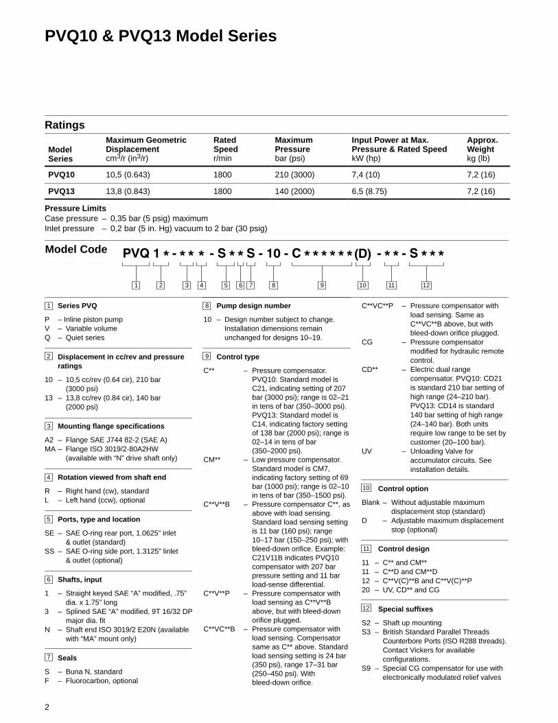
PVQ10 & PVQ13 Model Series
Ratings
ModelSeries
Maximum GeometricDisplacementcm3/r (in3/r)
RatedSpeedr/min
MaximumPressurebar (psi)
Input Power at Max.Pressure & Rated SpeedkW (hp)
Approx.Weightkg (lb)
PVQ10 10,5 (0.643) 1800 210 (3000) 7,4 (10) 7,2 (16)
PVQ13 13,8 (0.843) 1800 140 (2000) 6,5 (8.75) 7,2 (16)
Pressure LimitsCase pressure – 0,35 bar (5 psig) maximumInlet pressure – 0,2 bar (5 in. Hg) vacuum to 2 bar (30 psig)
3 4 5 876 9 101 2 11
Model Code
1
2
Series PVQ
P – Inline piston pumpV – Variable volumeQ – Quiet series
Displacement in cc/rev and pressureratings
10 – 10,5 cc/rev (0.64 cir), 210 bar(3000 psi)
13 – 13,8 cc/rev (0.84 cir), 140 bar(2000 psi)
Mounting flange specifications
A2 – Flange SAE J744 82-2 (SAE A)MA – Flange ISO 3019/2-80A2HW
(available with “N” drive shaft only)
Rotation viewed from shaft end
R – Right hand (cw), standardL – Left hand (ccw), optional
Ports, type and location
SE – SAE O-ring rear port, 1.0625” inlet& outlet (standard)
SS – SAE O-ring side port, 1.3125” linlet& outlet (optional)
Shafts, input
1 – Straight keyed SAE “A” modified, .75”dia. x 1.75” long
3 – Splined SAE “A” modified, 9T 16/32 DPmajor dia. fit
N – Shaft end ISO 3019/2 E20N (availablewith “MA” mount only)
Seals
S – Buna N, standardF – Fluorocarbon, optional
3
4
5
6
7
8
9
11
10
Pump design number
10 – Design number subject to change.Installation dimensions remainunchanged for designs 10–19.
Control type
C** – Pressure compensator.PVQ10: Standard model isC21, indicating setting of 207bar (3000 psi); range is 02–21in tens of bar (350–3000 psi).PVQ13: Standard model isC14, indicating factory settingof 138 bar (2000 psi); range is02–14 in tens of bar(350–2000 psi).
CM** – Low pressure compensator.Standard model is CM7,indicating factory setting of 69bar (1000 psi); range is 02–10in tens of bar (350–1500 psi).
C**V**B – Pressure compensator C**, asabove with load sensing.Standard load sensing settingis 11 bar (160 psi); range10–17 bar (150–250 psi); withbleed-down orifice. Example:C21V11B indicates PVQ10compensator with 207 barpressure setting and 11 barload-sense differential.
C**V**P – Pressure compensator withload sensing as C**V**Babove, but with bleed-downorifice plugged.
C**VC**B – Pressure compensator withload sensing. Compensatorsame as C** above. Standardload sensing setting is 24 bar(350 psi), range 17–31 bar(250–450 psi). Withbleed-down orifice.
C**VC**P – Pressure compensator withload sensing. Same asC**VC**B above, but withbleed-down orifice plugged.
CG – Pressure compensatormodified for hydraulic remotecontrol.
CD** – Electric dual rangecompensator. PVQ10: CD21is standard 210 bar setting ofhigh range (24–210 bar).PVQ13: CD14 is standard140 bar setting of high range(24–140 bar). Both unitsrequire low range to be set bycustomer (20–100 bar).
UV – Unloading Valve foraccumulator circuits. Seeinstallation details.
Control option
Blank – Without adjustable maximumdisplacement stop (standard)
D – Adjustable maximum displacementstop (optional)
Control design
11 – C** and CM**11 – C**D and CM**D12 – C**V(C)**B and C**V(C)**P20 – UV, CD** and CG
Special suffixes
S2 – Shaft up mountingS3 – British Standard Parallel Threads
Counterbore Ports (ISO R288 threads).Contact Vickers for availableconfigurations.
S9 – Special CG compensator for use withelectronically modulated relief valves
12
12
3
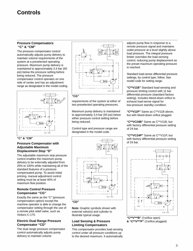
Controls
Pressure Compensators “C” & “CM”The pressure compensator controlautomatically adjusts pump delivery tomaintain volume requirements of thesystem at a preselected operatingpressure. Maximum pump delivery ismaintained to approximately 3,4 bar (50psi) below the pressure setting beforebeing reduced. The pressurecompensator control operates on oneside of center and has an adjustmentrange as designated in the model coding.
“C” & “CM”
Pressure Compensator withAdjustable MaximumDisplacement Stop “D”The adjustable maximum stop pressurecontrol enables the maximum pumpdelivery to be externally adjusted from25% to 100% while maintaining all of thestandard features of a pressurecompensated pump. To assist initialpriming, manual adjustment controlsetting must be at least 40% ofmaximum flow position.
Remote Control PressureCompensator “CG”Exactly the same as the “C” (pressurecompensation option) except themachine operator is able to change thecompensator setting through the use ofa remote pilot relief valve, such asVickers C-175.
Electric Dual Range PressureCompensator “CD”The dual range pressure compensatorcontrol automatically adjusts pumpdelivery to maintain volume
“CG”
requirements of the system at either oftwo preselected operating pressures.
Maximum pump delivery is maintainedto approximately 3,4 bar (50 psi) beloweither pressure control setting beforebeing reduced.
Control type and pressure range aredesignated in the model code.
“CD”
Note: Graphic symbols shown withexternal valve(s) and cylinder toillustrate typical usage.
Load Sensing & PressureLimiting CompensatorsThis compensator provides load sensingcontrol under all pressure conditions upto the desired maximum. It automatically
adjusts pump flow in response to aremote pressure signal and maintainsoutlet pressure at a level slightly aboveload pressure. The integral pressurelimiter overrides the load sensingcontrol, reducing pump displacement asthe preset maximum operating pressureis reached.
Standard load-sense differential pressuresettings, by control type, follow. Seemodel code for setting range.
“C**V11B” Standard load-sensing andpressure limiting control with 11 bardifferential pressure (standard factorysetting). Includes bleed-down orifice toexhaust load-sense signal forlow-pressure standby condition.
“C**V11P” Same as C**V11B above,but with bleed-down orifice plugged.
“C**VC24B” Same as C**V11B, butwith factory differential pressure settingof 24 bar.
“C**VC24P” Same as C**V11P, butwith factory differential pressure settingof 24 bar.
“C**V***B” (�orifice open)& “C**V***P” (�orifice plugged)
�
4
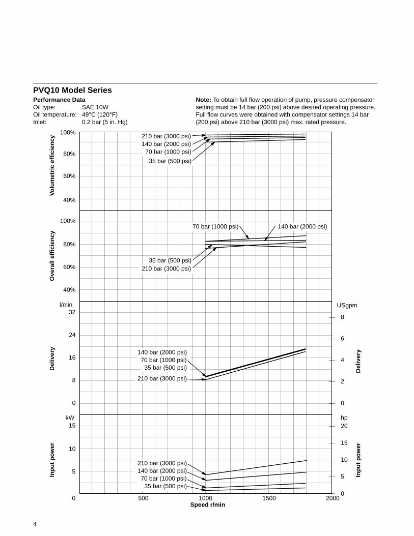
PVQ10 Model SeriesPerformance DataOil type: SAE 10WOil temperature: 49°C (120°F)Inlet: 0.2 bar (5 in. Hg)
Speed r/min0 500 1000 1500 2000
5
10
15
0
2
4
6
8
kW
USgpm
210 bar (3000 psi)140 bar (2000 psi)
70 bar (1000 psi)
35 bar (500 psi)
210 bar (3000 psi)
140 bar (2000 psi)70 bar (1000 psi)
35 bar (500 psi)
210 bar (3000 psi)140 bar (2000 psi)70 bar (1000 psi)
35 bar (500 psi)
Note: To obtain full flow operation of pump, pressure compensatorsetting must be 14 bar (200 psi) above desired operating pressure.Full flow curves were obtained with compensator settings 14 bar(200 psi) above 210 bar (3000 psi) max. rated pressure.
40%
60%
80%
100%
Volu
met
ric
effi
cien
cy
40%
60%
80%
100%
35 bar (500 psi)210 bar (3000 psi)
70 bar (1000 psi) 140 bar (2000 psi)
Ove
rall
effi
cien
cyD
eliv
ery
32
0
8
16
24
l/min
Del
iver
y
hp
Inp
ut
po
wer
0
5
10
15
20
Inp
ut
po
wer
5
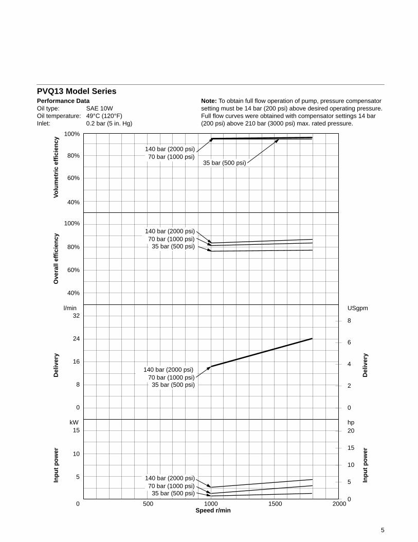
PVQ13 Model SeriesPerformance DataOil type: SAE 10WOil temperature: 49°C (120°F)Inlet: 0.2 bar (5 in. Hg)
Speed r/min0 500 1000 1500 2000
5
10
15
0
2
4
6
8
kW
USgpm
Note: To obtain full flow operation of pump, pressure compensatorsetting must be 14 bar (200 psi) above desired operating pressure.Full flow curves were obtained with compensator settings 14 bar(200 psi) above 210 bar (3000 psi) max. rated pressure.
40%
60%
80%
100%
Volu
met
ric
effi
cien
cy
40%
60%
80%
100%
Ove
rall
effi
cien
cyD
eliv
ery
32
0
8
16
24
l/min
Del
iver
y
hp
Inp
ut
po
wer
0
5
10
15
20
Inp
ut
po
wer
140 bar (2000 psi)70 bar (1000 psi)
35 bar (500 psi)
70 bar (1000 psi)140 bar (2000 psi)
70 bar (1000 psi)140 bar (2000 psi)
70 bar (1000 psi)35 bar (500 psi)
140 bar (2000 psi)
35 bar (500 psi)
35 bar (500 psi)
6
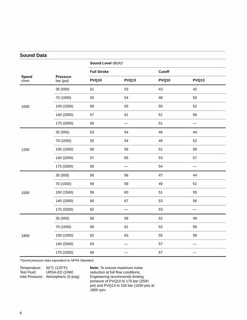
Sound Data
Sound Level dB(A)*
Speed Pre reFull Stroke Cutoff
Speedr/min
Pressurebar (psi) PVQ10 PVQ13 PVQ10 PVQ13
35 (500) 51 53 43 42
70 (1000) 55 54 48 50
1000 100 (1500) 56 55 50 52
140 (2000) 57 61 51 56
175 (2500) 59 — 51 —
35 (500) 53 54 46 44
70 (1000) 55 54 49 52
1200 100 (1500) 56 58 51 56
140 (2000) 57 65 53 57
175 (2500) 60 — 54 —
35 (500) 56 56 47 44
70 (1000) 59 59 49 51
1500 100 (1500) 59 60 51 55
140 (2000) 60 67 53 56
175 (2500) 62 — 53 —
35 (500) 58 58 52 49
70 (1000) 60 61 53 56
1800 100 (1500) 62 63 55 58
140 (2000) 63 — 57 —
175 (2500) 65 — 57 —
*Sound pressure data equivalent to NFPA Standard.
Temperature: 50°C (120°F)Test Fluid: URSA-ED (10W)Inlet Pressure: Atmospheric (0 psig)
Note: To ensure maximum noisereduction at full flow conditions,Engineering recommends limitingpressure of PVQ10 to 175 bar (2500psi) and PVQ13 to 100 bar (1500 psi) at1800 rpm.
7
Response DataYoke response recorded at rated speed and pressure, 0 psi inlet, 82°C (180°F), SAE 10W oil. Pressure rise was 6900 bar(100,000 psi) per second.
PVQ10 PVQ13
Control Type On stroke Off stroke On stroke Off stroke
Pressure compensator 0.040 sec. 0.020 sec. 0.048 sec. 0.016 sec.
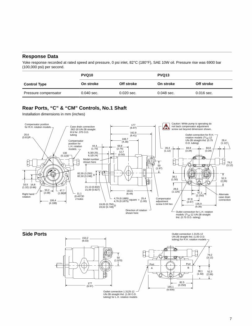
Rear Ports, “C” & “CM” Controls, No.1 ShaftInstallation dimensions in mm (inches)
Side Ports
Compensator positionfor R.H. rotation models Case drain connection
.562-18 UN-2B straightth’d for .375 O.D.tubing
Compensatorposition forL.H. rotationmodels
20,6(0.81)R
33,5(1.32)
16,8(0.66)
Right handrotation
106,4(4.188)
53,2(2.09) 11,1
(0.437)D2 holes
177(6.97)
162,8(6.41)
108,7(4.28)
69,8(2.75)
44,4(1.75)
6,36,1
(0.25)(0.24)
12,7(0.50)
Model numbershown here
82,55 (3.250)82,50 (3.248) D
21,13 (0.832)21,00 (0.827)
19,05 (0.750)19,02 (0.749) D
4,79 (0.1885)4,76 (0.1875)
25,4(1.00)
163,6(6.44)
Direction of rotationshown here
Compensatoradjustmentscrew 0.94 hex
50(1.97)
Caution: While pump is operating donot back compensator adjustmentscrew out beyond dimension shown.
Outlet connection for R.H.rotation models 11/16-12UN-2B straight thd. (0.75O.D. tubing)
28,4(1.12)
84,8(3.34)
84,8(3.34)
28,4(1.12)
79,2(3.12)
52,3(2.06)
Alternatecase drainconnection
Outlet connection for L.H. rotationmodels 11/16-12 UN-2B straightthd. (0.75 O.D. tubing)
135,9(5.35)
67,8(2.67)
57,1(2.250)
28,6(1.125)
38,1(1.50)
130(5.12)D
153,2(6.03)
50(1.970)
177(6.97)
Outlet connection 1.3125-12UN-2B straight thd. (1.00 O.D.tubing) for L.H. rotation models
Outlet connection 1.3125-12UN-2B straight thd. (1.00 O.D.tubing) for R.H. rotation models
Port
A
Port
B
79,2(3.12)
52,3(2.06)
165,1(6.500)
82,5(3.250)
38,1(1.50)
square �
47,7(1.88)R
A B
8
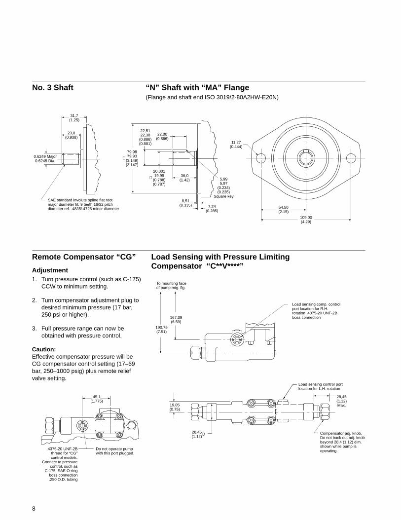
No. 3 Shaft “N” Shaft with “MA” Flange(Flange and shaft end ISO 3019/2-80A2HW-E20N)
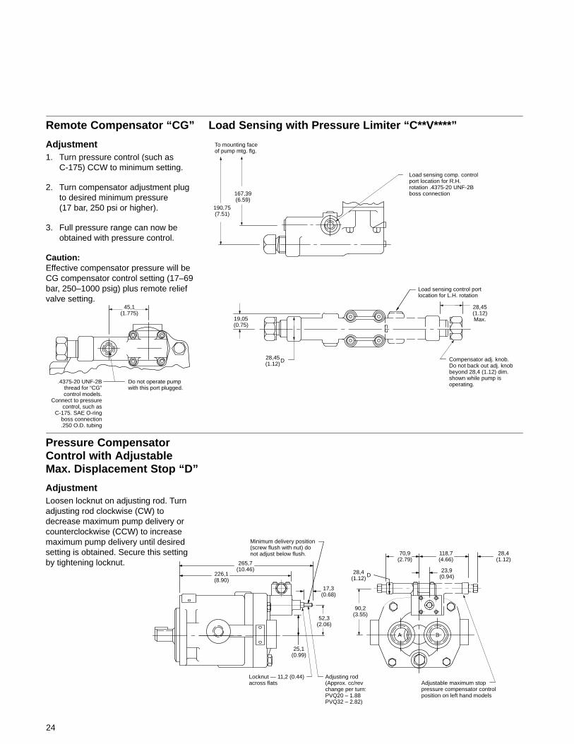
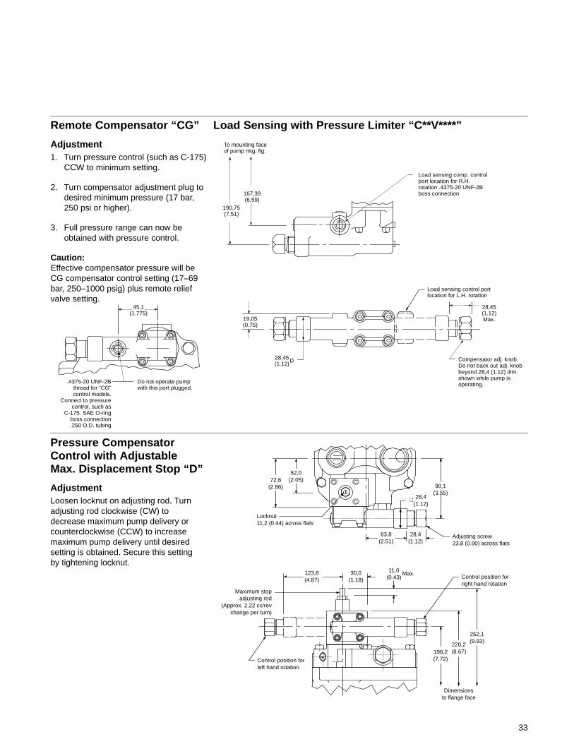
Remote Compensator “CG”
Adjustment1. Turn pressure control (such as C-175)
CCW to minimum setting.
2. Turn compensator adjustment plug todesired minimum pressure (17 bar,250 psi or higher).
3. Full pressure range can now beobtained with pressure control.
Caution:Effective compensator pressure will beCG compensator control setting (17–69bar, 250–1000 psig) plus remote reliefvalve setting.
Load Sensing with Pressure Limiting Compensator “C**V****”
31,7(1.25)
0.6249 Major0.6245 Dia.
SAE standard involute spline flat rootmajor diameter fit. 9 teeth 16/32 pitchdiameter ref. .4835/.4725 minor diameter
79,9879,93
(3.149)(3.147)
22,5122,38
(0.886)(0.881)
∅
20,00119,99
(0.788)(0.787)
∅
22,00(0.866)
36,0(1.42)
8,51(0.335) 7,24
(0.285)
5,995,97
(0.234)(0.235)
Square key
Load sensing control portlocation for L.H. rotation
To mounting faceof pump mtg. flg.
Load sensing comp. controlport location for R.H.rotation .4375-20 UNF-2Bboss connection
190,75(7.51)
167,39(6.59)
28,45(1.12)Max.
Compensator adj. knob.Do not back out adj. knobbeyond 28,4 (1.12) dim.shown while pump isoperating.
28,45(1.12)
D
19,05(0.75)
45,1(1.775)
Do not operate pumpwith this port plugged.
.4375-20 UNF-2Bthread for “CG”control models.
Connect to pressurecontrol, such as
C-175. SAE O-ringboss connection.250 O.D. tubing
23,8(0.938)
109,00(4.29)
54,50(2.15)
11,27(0.444)
9
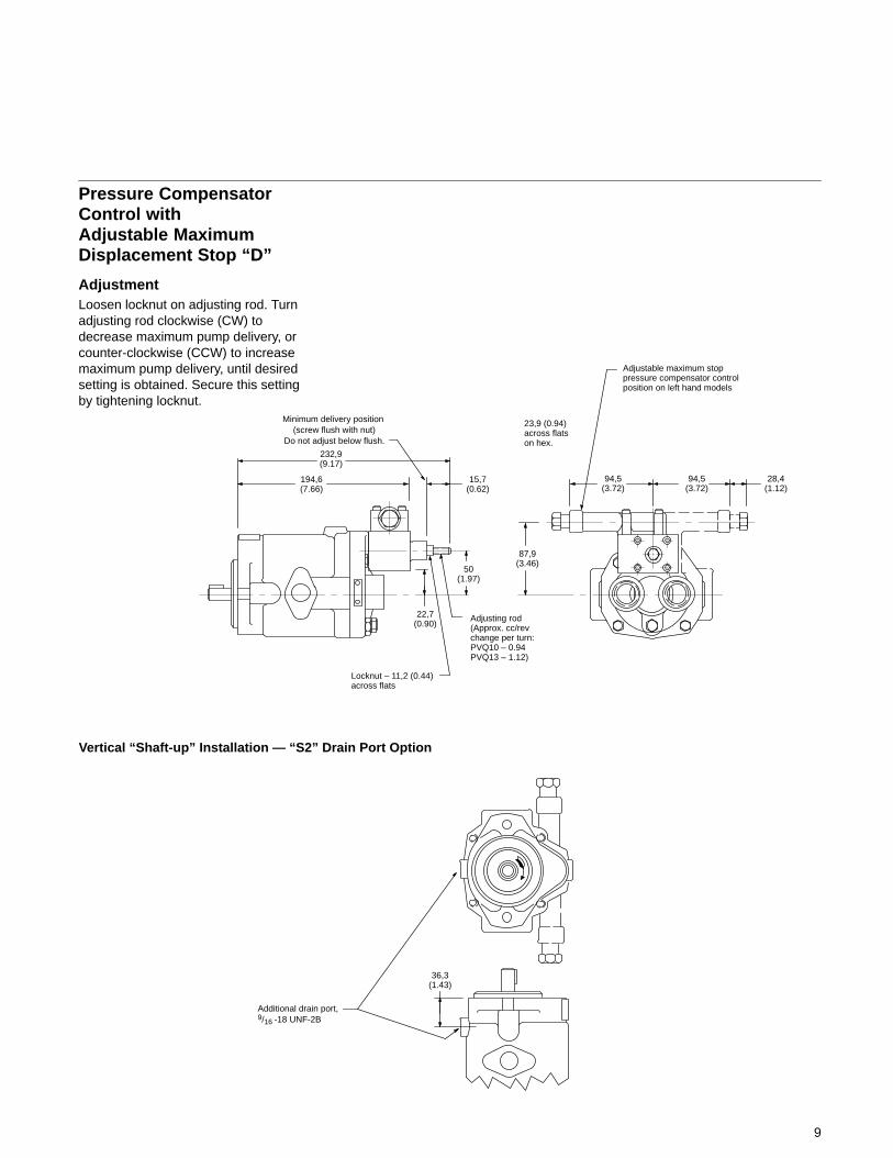
Pressure CompensatorControl withAdjustable MaximumDisplacement Stop “D”
AdjustmentLoosen locknut on adjusting rod. Turnadjusting rod clockwise (CW) todecrease maximum pump delivery, orcounter-clockwise (CCW) to increasemaximum pump delivery, until desiredsetting is obtained. Secure this settingby tightening locknut.
Vertical “Shaft-up” Installation — “S2” Drain Port Option
232,9(9.17)
194,6(7.66)
Minimum delivery position (screw flush with nut)
Do not adjust below flush.
Adjustable maximum stoppressure compensator controlposition on left hand models
22,7(0.90)
15,7(0.62)
87,9(3.46)
50(1.97)
Adjusting rod(Approx. cc/revchange per turn:PVQ10 – 0.94PVQ13 – 1.12)
94,5(3.72)
28,4(1.12)
23,9 (0.94) across flats on hex.
Locknut – 11,2 (0.44)across flats
94,5(3.72)
36,3(1.43)
Additional drain port,9/16 -18 UNF-2B

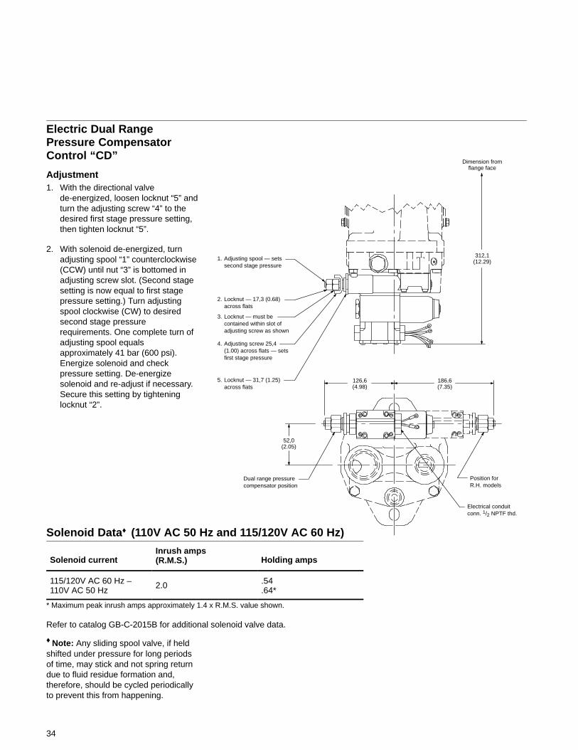
Electric Dual RangePressure CompensatorControl “CD”
Adjustment1. With the directional valve
de-energized, loosen locknut “5” andturn the adjusting screw “4” to thedesired first stage pressure setting,then tighten locknut “5”.
2. With solenoid de-energized, turnadjusting spool “1” counterclockwise(CCW) until nut “3” is bottomed inadjusting screw slot. (Second stagesetting is now equal to first stagepressure setting.) Turn adjustingspool clockwise (CW) to desiredsecond stage pressurerequirements. One complete turn ofadjusting spool equalsapproximately 41 bar (600 psi).Energize solenoid and checkpressure setting. De-energizesolenoid and re-adjust if necessary.Secure this setting by tighteninglocknut “2”.
1. Adjusting spool — setssecond stage pressure 288,5
(11.36)
158,7(6.25)
158,7(6.25)
Position forR.H. models
Electrical conduitconn. 1/2 NPTF thd.
Dual range pressurecompensator position
50(1.97)
2. Locknut — 17,3 (0.68)across flats
3. Locknut — must becontained within slot ofadjusting screw as shown
4. Adjusting screw 25,4(1.00) across flats — setsfirst stage pressure
5. Locknut — 31,7 (1.25)across flats
10
Solenoid Data♦ (110V AC 50 Hz and 115/120V AC 60 Hz)
Solenoid currentInrush amps(R.M.S.) Holding amps
115/120V AC 60 Hz –110V AC 50 Hz
2.0 .54.64*
* Maximum peak inrush amps approximately 1.4 x R.M.S. value shown.
Refer to catalog GB-C-2015B for additional solenoid valve data.
♦ Note: Any sliding spool valve, if heldshifted under pressure for long periodsof time, may stick and not spring returndue to fluid residue formation and,therefore, should be cycled periodicallyto prevent this from happening.
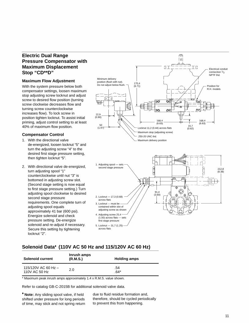
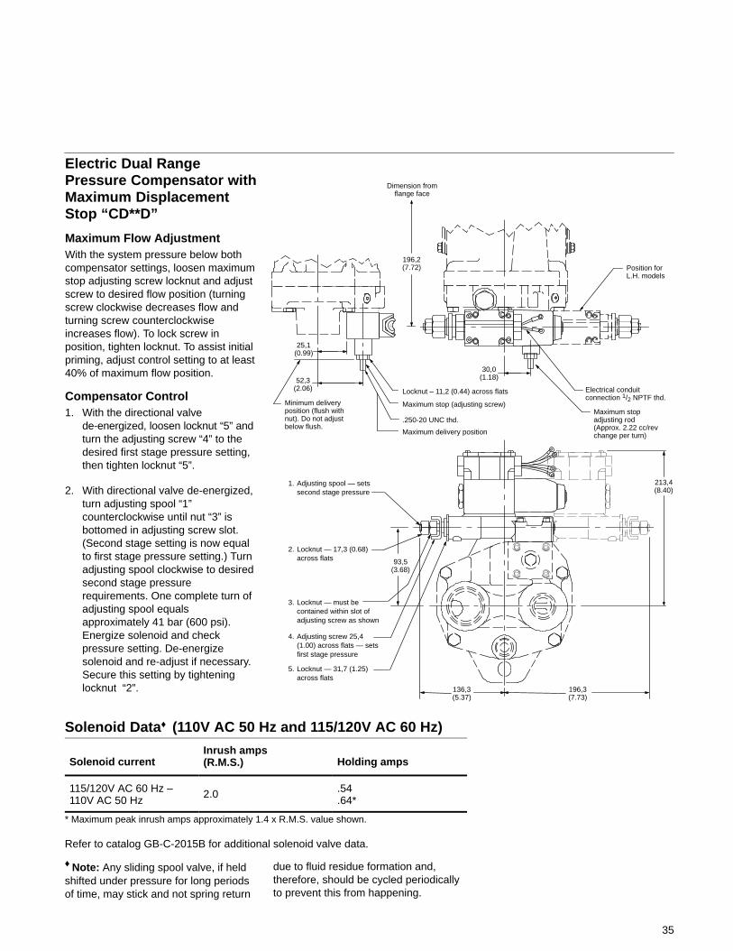
Electric Dual RangePressure Compensator withMaximum DisplacementStop “CD**D”
Maximum Flow AdjustmentWith the system pressure below bothcompensator settings, loosen maximumstop adjusting screw locknut and adjustscrew to desired flow position (turningscrew clockwise decreases flow andturning screw counterclockwiseincreases flow). To lock screw inposition tighten locknut. To assist initialpriming, adjust control setting to at least40% of maximum flow position.
Compensator Control1. With the directional valve
de-energized, loosen locknut “5” andturn the adjusting screw “4” to thedesired first stage pressure setting,then tighten locknut “5”.
2. With directional valve de-energized,turn adjusting spool “1”counterclockwise until nut “3” isbottomed in adjusting screw slot.(Second stage setting is now equalto first stage pressure setting.) Turnadjusting spool clockwise to desiredsecond stage pressurerequirements. One complete turn ofadjusting spool equalsapproximately 41 bar (600 psi).Energize solenoid and checkpressure setting. De-energizesolenoid and re-adjust if necessary.Secure this setting by tighteninglocknut “2”.
Electrical conduitconnection 1/2NPTF thd.
168,4(6.63)
Position forR.H. models
168,4(6.63)
170,4(6.71)
91,4(3.60)
212,8(8.38)
Minimum deliveryposition (flush with nut).Do not adjust below flush.
15,7(0.62)
Maximum delivery position
Locknut 11,2 (0.44) across flats
Maximum stop (adjusting screw)
.250-20 UNC thd.
50(1.97)
22,9(0.90)
1. Adjusting spool — setssecond stage pressure
2. Locknut — 17,3 (0.68)across flats
3. Locknut — must becontained within slot ofadjusting screw as shown
4. Adjusting screw 25,4(1.00) across flats — setsfirst stage pressure
5. Locknut — 31,7 (1.25)across flats
11
Solenoid Data♦ (110V AC 50 Hz and 115/120V AC 60 Hz)
Solenoid currentInrush amps(R.M.S.) Holding amps
115/120V AC 60 Hz –110V AC 50 Hz
2.0 .54.64*
* Maximum peak inrush amps approximately 1.4 x R.M.S. value shown.
Refer to catalog GB-C-2015B for additional solenoid valve data.
♦ Note: Any sliding spool valve, if heldshifted under pressure for long periodsof time, may stick and not spring return
due to fluid residue formation and,therefore, should be cycled periodicallyto prevent this from happening.
12
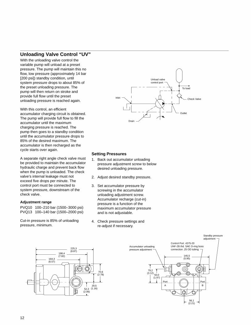
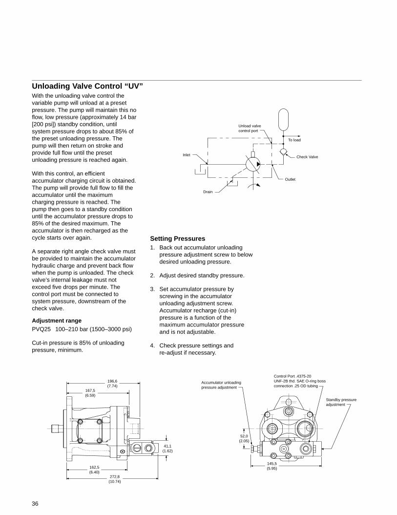
With the unloading valve control thevariable pump will unload at a presetpressure. The pump will maintain this noflow, low pressure (approximately 14 bar[200 psi]) standby condition, untilsystem pressure drops to about 85% ofthe preset unloading pressure. Thepump will then return on stroke andprovide full flow until the presetunloading pressure is reached again.
With this control, an efficientaccumulator charging circuit is obtained.The pump will provide full flow to fill theaccumulator until the maximumcharging pressure is reached. Thepump then goes to a standby conditionuntil the accumulator pressure drops to85% of the desired maximum. Theaccumulator is then recharged as thecycle starts over again.
A separate right angle check valve mustbe provided to maintain the accumulatorhydraulic charge and prevent back flowwhen the pump is unloaded. The checkvalve’s internal leakage must notexceed five drops per minute. Thecontrol port must be connected tosystem pressure, downstream of thecheck valve.
Adjustment rangePVQ10 100–210 bar (1500–3000 psi)PVQ13 100–140 bar (1500–2000 psi)
Cut-in pressure is 85% of unloadingpressure, minimum.
225,3(8.87)
70,6(2.78)
198,4(7.82)
164,3(6.57)
145,5(5.95)
29,5(1.16)52,3
(2.06)
50,0(1.97)
79,2(3.12)
Accumulator unloadingpressure adjustment
Control Port .4375-20UNF-2B thd. SAE O-ring bossconnection .25 OD tubing
Setting Pressures1. Back out accumulator unloading
pressure adjustment screw to belowdesired unloading pressure.
2. Adjust desired standby pressure.
3. Set accumulator pressure byscrewing in the accumulatorunloading adjustment screw.Accumulator recharge (cut-in)pressure is a function of themaximum accumulator pressureand is not adjustable.
4. Check pressure settings andre-adjust if necessary.
Outlet
Drain
Inlet Check Valve
To load
Unload valvecontrol port
56,1(2.21)
Standby pressureadjustment
Unloading Valve Control “UV”
Port
A
Port
B
13
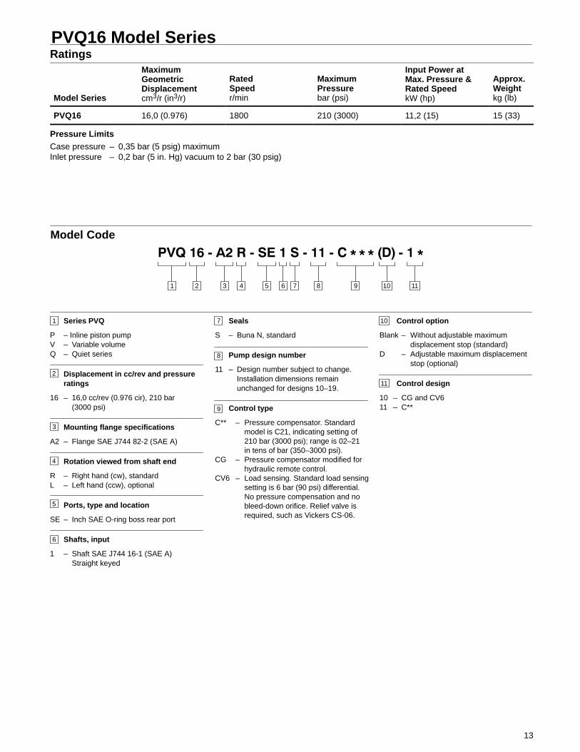
PVQ16 Model SeriesRatings
Model Series
MaximumGeometricDisplacementcm3/r (in3/r)
RatedSpeedr/min
MaximumPressurebar (psi)
Input Power atMax. Pressure &Rated SpeedkW (hp)
Approx.Weightkg (lb)
PVQ16 16,0 (0.976) 1800 210 (3000) 11,2 (15) 15 (33)
Pressure LimitsCase pressure – 0,35 bar (5 psig) maximumInlet pressure – 0,2 bar (5 in. Hg) vacuum to 2 bar (30 psig)
3 4 5 876 9 101 2 11
Model Code
1
2
Series PVQ
P – Inline piston pumpV – Variable volumeQ – Quiet series
Displacement in cc/rev and pressureratings
16 – 16,0 cc/rev (0.976 cir), 210 bar(3000 psi)
Mounting flange specifications
A2 – Flange SAE J744 82-2 (SAE A)
Rotation viewed from shaft end
R – Right hand (cw), standardL – Left hand (ccw), optional
Ports, type and location
SE – Inch SAE O-ring boss rear port
Shafts, input
1 – Shaft SAE J744 16-1 (SAE A)Straight keyed
3
4
5
6
7
8
9
11
10Seals
S – Buna N, standard
Pump design number
11 – Design number subject to change.Installation dimensions remainunchanged for designs 10–19.
Control type
C** – Pressure compensator. Standardmodel is C21, indicating setting of210 bar (3000 psi); range is 02–21in tens of bar (350–3000 psi).
CG – Pressure compensator modified forhydraulic remote control.
CV6 – Load sensing. Standard load sensingsetting is 6 bar (90 psi) differential.No pressure compensation and nobleed-down orifice. Relief valve isrequired, such as Vickers CS-06.
Control option
Blank – Without adjustable maximumdisplacement stop (standard)
D – Adjustable maximum displacementstop (optional)
Control design
10 – CG and CV611 – C**
14
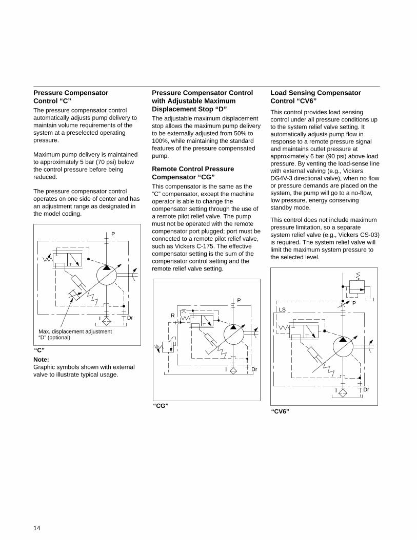
Pressure CompensatorControl “C”The pressure compensator controlautomatically adjusts pump delivery tomaintain volume requirements of thesystem at a preselected operatingpressure.
Maximum pump delivery is maintainedto approximately 5 bar (70 psi) belowthe control pressure before beingreduced.
The pressure compensator controloperates on one side of center and hasan adjustment range as designated inthe model coding.
“C”
I Dr
P
Max. displacement adjustment “D” (optional)
Note:Graphic symbols shown with externalvalve to illustrate typical usage.
Pressure Compensator Controlwith Adjustable MaximumDisplacement Stop “D”The adjustable maximum displacementstop allows the maximum pump deliveryto be externally adjusted from 50% to100%, while maintaining the standardfeatures of the pressure compensatedpump.
Remote Control PressureCompensator “CG”This compensator is the same as the“C” compensator, except the machineoperator is able to change thecompensator setting through the use ofa remote pilot relief valve. The pumpmust not be operated with the remotecompensator port plugged; port must beconnected to a remote pilot relief valve,such as Vickers C-175. The effectivecompensator setting is the sum of thecompensator control setting and theremote relief valve setting.
“CG”
I Dr
P
R
Load Sensing CompensatorControl “CV6”
This control provides load sensingcontrol under all pressure conditions upto the system relief valve setting. Itautomatically adjusts pump flow inresponse to a remote pressure signaland maintains outlet pressure atapproximately 6 bar (90 psi) above loadpressure. By venting the load-sense linewith external valving (e.g., VickersDG4V-3 directional valve), when no flowor pressure demands are placed on thesystem, the pump will go to a no-flow,low pressure, energy conservingstandby mode.
This control does not include maximumpressure limitation, so a separatesystem relief valve (e.g., Vickers CS-03)is required. The system relief valve willlimit the maximum system pressure tothe selected level.
“CV6”
I Dr
PLS
15
Del
iver
y –
l/min
(U
Sg
pm
)
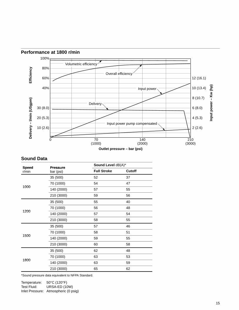
Performance at 1800 r/min
0 140(2000)
210(3000)
Outlet pressure – bar (psi)
2 (2.6)
70(1000)
4 (5.3)
6 (8.0)
8 (10.7)
10 (13.4)
12 (16.1)
10 (2.6)
20 (5.3)
30 (8.0)
40%
60%
80%
100%
Eff
icie
ncy
Volumetric efficiency
Overall efficiency
Input power
Input power pump compensated
Delivery
Inp
ut
po
wer
– K
w (
hp
)
Sound Data
Speed Press reSound Level dB(A)*
Speedr/min
Pressurebar (psi) Full Stroke Cutoff
35 (500) 52 37
100070 (1000) 54 47
1000140 (2000) 57 55
210 (3000) 59 56
35 (500) 55 40
120070 (1000) 56 48
1200140 (2000) 57 54
210 (3000) 58 55
35 (500) 57 46
150070 (1000) 58 51
1500140 (2000) 59 55
210 (3000) 60 58
35 (500) 62 48
180070 (1000) 63 53
1800140 (2000) 63 59
210 (3000) 65 62
*Sound pressure data equivalent to NFPA Standard.
Temperature: 50°C (120°F)Test Fluid: URSA-ED (10W)Inlet Pressure: Atmospheric (0 psig)
16
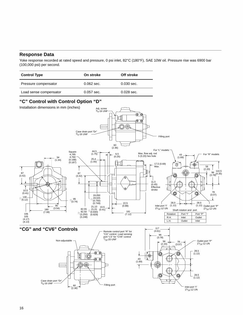
Response DataYoke response recorded at rated speed and pressure, 0 psi inlet, 82°C (180°F), SAE 10W oil. Pressure rise was 6900 bar(100,000 psi) per second.
Control Type On stroke Off stroke
Pressure compensator 0.062 sec. 0.030 sec.
Load sense compensator 0.057 sec. 0.028 sec.
Rotation Port “I” Port “P”
R.H. Inlet Outlet
L.H. Outlet Inlet
“C” Control with Control Option “D”Installation dimensions in mm (inches)
“CG” and “CV6” Controls
Non-adjustable
Adj. screw 3/4-16 UNF
Case drain port “Dr”3/4-16 UNF
Filling port
60(2.36)
87(3.42)
34(1.34)
10,5(0.41)
130(5.12)∅
106105
(4.17)(4.13)
180(7.08)
90(3.54)
95(3.74)∅
Square4,7854,760
(0.188)(0.187)
44,5(1.75) 6,5
(0.25)25,4
(1.00)
87(3.42)
82,5582,50
(3.250)(3.248)
∅
21,1321,01
(0.830)(0.829)
∅
19,05019,025(0.750)(0.749)
∅
10,5(0.41)
22,5(0.88)
181(7.12)
Max. flow adj. rod5 (0.20) hex hole
17,5 (0.69)Max.
11,5(0.45)Effectivestroke
For “L” models
For “R” models43(1.69)
56(2.20)
96(3.78)
110,5(4.35)
78(3.07)
Outlet port “P”11/16-12 UN
Inlet port “I” 11/16-12 UN
28,5(1.12)
Shaft rotation and port
Remote control port “R” for“CG” control. Load sensingport “LS” for “CV6” control7/16-20 UNF
117(4.61)
96(3.78)
56(2.20)
78(3.07)
Outlet port “P”11/16-12 UN
28,5(1.12)
Inlet port “I”11/16-12 UN
43(1.69)
Filling port
Case drain port “Dr”3/4-16 UNF
60(2.36)
28,5(1.12)
28,5(1.12)

17
PVQ20 & PVQ32 Model Series
Ratings
ModelSeries
Maximum GeometricDisplacementcm3/r (in3/r)
RatedSpeedr/min
MaximumPressurebar (psi)
Input Power at Max.Pressure & Rated SpeedkW (hp)
Approx.Weightkg (lb)
PVQ20 21,1 (1.290) 1800 210 (3000) 14,9 (20) 14 (31)
PVQ32 32,9 (2.010) 1800 140 (2000) 15,6 (21) 14 (31)
Pressure LimitsCase pressure – 0,35 bar (5 psig) maximumInlet pressure – 0,2 bar (5 in. Hg) vacuum to 2 bar (30 psig)
3 4 5 876 9 101 2 11
Model Code
1
2
Series PVQ
P – Inline piston pumpV – Variable volumeQ – Quiet series
Displacement in cc/rev and pressureratings
20 – 21,1 cc/rev (1.29 cir), 210 bar(3000 psi)
32 – 32,9 cc/rev (2.01 cir), 140 bar(2000 psi)
Mounting flange specifications
B2 – Flange SAE J744 101-2 (SAE B)MB – Flange ISO 3019/2-100A2HW
(available with “N” drive shaft only)
Rotation viewed from shaft end
R – Right hand (cw), standardL – Left hand (ccw), optional
Thru-drive without coupling(available with side ports only)
Blank – No thru-driveA9 – SAE J744 82-2 (SAE A) w/9T splineA11 – SAE J744 82-2 (SAE A) w/11T spline
Ports, type and location
SE – SAE O-ring rear port, 1.625” inlet& outlet (standard)
SS – SAE O-ring side port, 1.625” linlet& outlet (optional)
Shafts, input
1 – Straight keyed SAE “B” modified,2.31” long
3 – Splined SAE “B” modified, 13T16/32 DP major dia. fit
N – Shaft end ISO 3019/2 E25N (availablewith “MB” mount only)
28 – 26-tooth splined shaft (Vickers). Usedin PVQ20/32 single to mount onPVQ40/45 “B26” thru-drive.
3
4
5
6
7
8
11
10
Seals
S – Buna N, standardF – Fluorocarbon, optional
Pump design number
10 – Design number subject to change.Installation dimensions remainunchanged for designs 10–19.
Control type
C** – Pressure compensator.PVQ20: Standard model isC21, indicating setting of 207bar (3000 psi); range is 02–21in tens of bar (350–3000 psi).PVQ32: Standard model isC14, indicating factory settingof 138 bar (2000 psi); range is02–14 in tens of bar(350–2000 psi).
CM** – Low pressure compensator.Standard model is CM7,indicating factory setting of 70bar (1000 psi); range is 02–10in tens of bar (350–2000 psi).
C**V**B – Pressure compensator C**, asabove with load sensing.Standard load sensing settingis 11 bar (160 psi); range10–17 bar (150–250 psi); withbleed-down orifice. Example:C21V11B indicates PVQ20compensator with 210 barpressure setting and 11 barload-sense differential.
C**V**P – Pressure compensator withload sensing as C**V**Babove, but with bleed-downorifice plugged.
C**VC**B – Pressure compensator withload sensing. Compensatorsame as C** above. Standardload sensing setting is 24 bar
(350 psi), range 17–31 bar(250–450 psi). Withbleed-down orifice.
C**VC**P – Pressure compensator withload sensing. Same asC**VC**B above, but withbleed-down orifice plugged.
CG – Pressure compensatormodified for hydraulic remotecontrol.
CD** – Electric dual rangecompensator. PVQ20: CD21is standard 207 bar setting ofhigh range (24–210 bar).PVQ32: CD14 is standard140 bar setting of high range(24–140 bar). Both unitsrequire low range to be set bycustomer (20–100 bar).
UV – Unloading Valve foraccumulator circuits. Seeinstallation details.
Control option
Blank – Without adjustable maximumdisplacement stop (standard)
D – Adjustable maximum displacementstop (optional)
Control design
11 – C** and CM**11 – C**D and CM**D12 – C**V(C)**B and C**V(C)**P20 – UV, CD** and CG
Special suffixes
S2 – Shaft up mountingS3 – British Standard Parallel Threads
Counterbore Ports (ISO R288 threads).Contact Vickers for availableconfigurations.
S9 – Special CG compensator for use withelectronically modulated relief valves
12
12
13
13
9

18
Pressure Compensator Controls“C” & “CM”The pressure compensator controlautomatically adjusts pump delivery tomaintain volume requirements of thesystem at a preselected operatingpressure. Maximum pump delivery ismaintained to approximately 75 psi(PVQ20) or 100 psi (PVQ32) below thepressure setting before being reduced.The pressure compensator controloperates on one side of center and hasan adjustment range as designated inthe model coding.
“C” & “CM”
Pressure Compensator Controlwith Adjustable MaximumDisplacement Stop “D”The adjustable maximum stop pressurecontrol enables the maximum pumpdelivery to be externally adjusted from25% to 100% while maintaining all of thestandard features of a pressurecompensated pump. To assist initialpriming, manual adjustment controlsetting must be at least 40% ofmaximum flow position.
Remote Control PressureCompensator “CG”Exactly the same as the “C” (pressurecompensation option) except themachine operator is able to change thecompensator setting through the use ofa remote pilot relief valve, such asVickers C-175.
Electric Dual Range PressureCompensator Control “CD”The dual range pressure compensatorcontrol automatically adjusts pump
“CG”
delivery to maintain volumerequirements of the system at either oftwo preselected operating pressures.
Maximum pump delivery is maintainedto approximately 75 psi (PVQ20) or 100psi (PVQ32) below either pressurecontrol setting before being reduced.
Control type and pressure range aredesignated in the model code.
“CD”
Note: Graphic symbols shown withexternal valve(s) and cylinder toillustrate typical usage.
Load Sensing & Pressure LimiterCompensator ControlThis compensator provides load sensingcontrol under all pressure conditions up
to the desired maximum. It automaticallyadjusts pump flow in response to aremote pressure signal and maintainsoutlet pressure at a level slightly aboveload pressure. The integral pressurelimiter overrides the load sensingcontrol, reducing pump displacement asthe preset maximum operating pressureis reached.
Standard load-sense differential pressuresettings, by control type, follow. Seemodel code for setting range.
“C**V11B” Standard load-sensing andpressure limiting control with 11 bardifferential pressure (standard factorysetting). Includes bleed-down orifice toexhaust load-sense signal forlow-pressure standby condition.
“C**V11P” Same as C**V11B above,but with bleed-down orifice plugged.
“C**VC24B” Same as C**V11B, butwith factory differential pressure settingof 24 bar.
“C**VC24P” Same as C**V11P, butwith factory differential pressure settingof 24 bar.
“C**V***B” (�orifice open)& “C**V***P” (�orifice plugged)
�
19
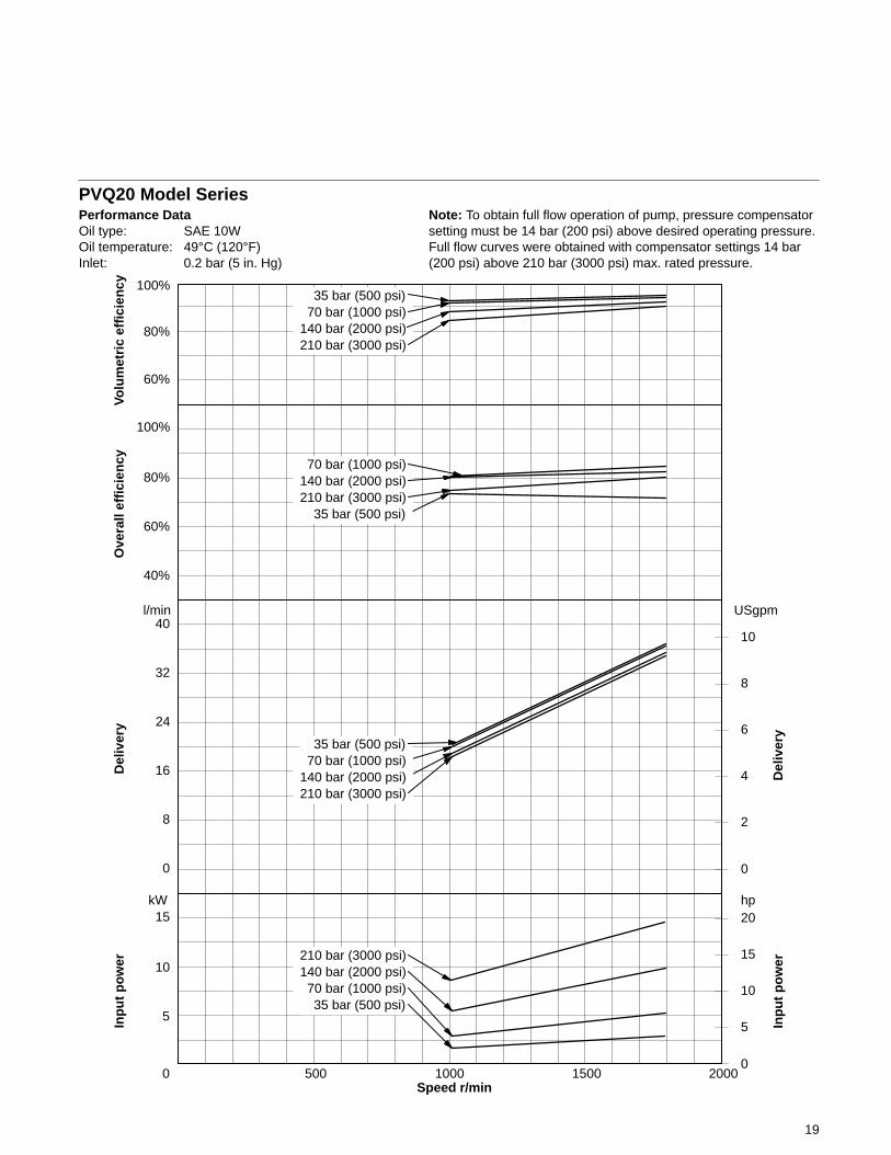
PVQ20 Model SeriesPerformance DataOil type: SAE 10WOil temperature: 49°C (120°F)Inlet: 0.2 bar (5 in. Hg)
Speed r/min0 500 1000 1500 2000
5
10
15
0
2
4
6
8
kW
Note: To obtain full flow operation of pump, pressure compensatorsetting must be 14 bar (200 psi) above desired operating pressure.Full flow curves were obtained with compensator settings 14 bar(200 psi) above 210 bar (3000 psi) max. rated pressure.
60%
80%
100%
Volu
met
ric
effi
cien
cy
40%
60%
80%
100%
Ove
rall
effi
cien
cyD
eliv
ery
32
0
8
16
24
Del
iver
y
hp
Inp
ut
po
wer
0
5
10
15
20
Inp
ut
po
wer
210 bar (3000 psi)140 bar (2000 psi) 70 bar (1000 psi) 35 bar (500 psi)
210 bar (3000 psi)
70 bar (1000 psi)140 bar (2000 psi)
210 bar (3000 psi)
35 bar (500 psi)
210 bar (3000 psi)140 bar (2000 psi) 70 bar (1000 psi) 35 bar (500 psi)
40l/min
10
USgpm
35 bar (500 psi)
70 bar (1000 psi)140 bar (2000 psi)
20
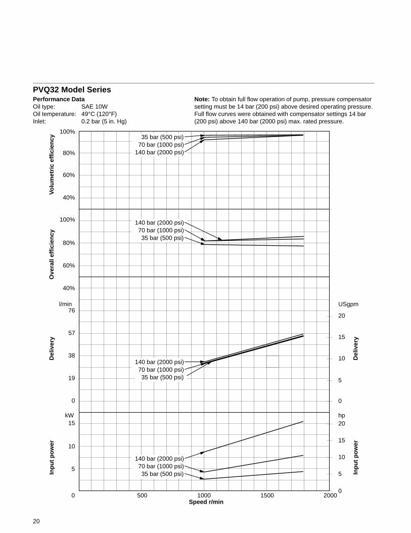
PVQ32 Model SeriesPerformance DataOil type: SAE 10WOil temperature: 49°C (120°F)Inlet: 0.2 bar (5 in. Hg)
Speed r/min0 500 1000 1500 2000
5
10
15
0
5
10
15
20
kW
Note: To obtain full flow operation of pump, pressure compensatorsetting must be 14 bar (200 psi) above desired operating pressure.Full flow curves were obtained with compensator settings 14 bar(200 psi) above 140 bar (2000 psi) max. rated pressure.
60%
80%
100%
Volu
met
ric
effi
cien
cy
40%
60%
80%
100%
Ove
rall
effi
cien
cyD
eliv
ery
76
0
19
38
57
Del
iver
y
hp
Inp
ut
po
wer
0
5
10
15
20
Inp
ut
po
wer
140 bar (2000 psi) 70 bar (1000 psi) 35 bar (500 psi)
35 bar (500 psi) 70 bar (1000 psi)
70 bar (1000 psi)140 bar (2000 psi)
70 bar (1000 psi) 35 bar (500 psi)
140 bar (2000 psi)
140 bar (2000 psi)
l/min USgpm
40%
35 bar (500 psi)
21
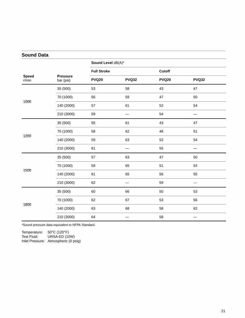
Sound Data
Sound Level dB(A)*
Speed Pre reFull Stroke Cutoff
Speedr/min
Pressurebar (psi) PVQ20 PVQ32 PVQ20 PVQ32
35 (500) 53 58 43 47
100070 (1000) 56 59 47 50
1000140 (2000) 57 61 52 54
210 (3000) 59 — 54 —
35 (500) 55 61 43 47
120070 (1000) 58 62 48 51
1200140 (2000) 59 63 52 54
210 (3000) 61 — 55 —
35 (500) 57 63 47 50
150070 (1000) 59 65 51 54
1500140 (2000) 61 65 56 55
210 (3000) 62 — 59 —
35 (500) 60 66 50 53
180070 (1000) 62 67 53 56
1800140 (2000) 63 68 58 62
210 (3000) 64 — 58 —
*Sound pressure data equivalent to NFPA Standard.
Temperature: 50°C (120°F)Test Fluid: URSA-ED (10W)Inlet Pressure: Atmospheric (0 psig)
22
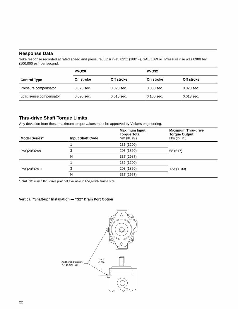
Response DataYoke response recorded at rated speed and pressure, 0 psi inlet, 82°C (180°F), SAE 10W oil. Pressure rise was 6900 bar(100,000 psi) per second.
PVQ20 PVQ32
Control Type On stroke Off stroke On stroke Off stroke
Pressure compensator 0.070 sec. 0.023 sec. 0.080 sec. 0.020 sec.
Load sense compensator 0.090 sec. 0.015 sec. 0.100 sec. 0.018 sec.
Thru-drive Shaft Torque LimitsAny deviation from these maximum torque values must be approved by Vickers engineering.
Model Series* Input Shaft Code
Maximum InputTorque TotalNm (lb. in.)
Maximum Thru-driveTorque OutputNm (lb. in.)
1 135 (1200)
PVQ20/32A9 3 208 (1850) 58 (517)
N 337 (2987)
( )
1 135 (1200)
PVQ20/32A11 3 208 (1850) 123 (1100)
N 337 (2987)
( )
* SAE “B” 4 inch thru-drive pilot not available in PVQ20/32 frame size.
Additional drain port,3/4”-16 UNF-2B
Vertical “Shaft-up” Installation — “S2” Drain Port Option
29,2(1.15)
23
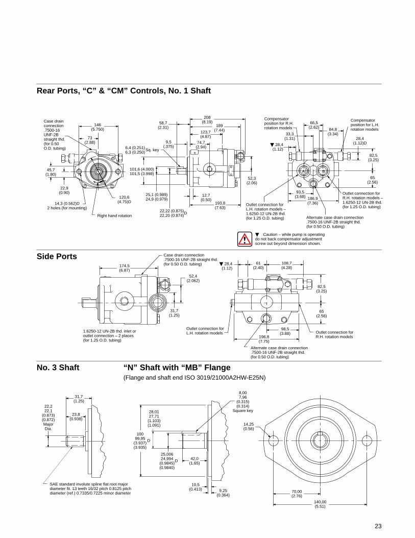
Side Ports
Rear Ports, “C” & “CM” Controls, No. 1 Shaft
146(5.750)
73(2.88)
120,6(4.75)D
Right hand rotation
22,9(0.90)
45,7(1.80)
14,3 (0.562)D2 holes (for mounting)
Case drainconnection.7500-16UNF-2Bstraight thd.(for 0.50O.D. tubing)
58,7(2.31)
208(8.19)
189(7.44)123,7
(4.87)
74,7(2.94)
9,5(.375)6,4 (0.251)
6,3 (0.250)Sq. key
101,6 (4.000)101,5 (3.998)
25,1 (0.989)24,9 (0.979)
22,22 (0.875)22,20 (0.874)D
12,7(0.50)
193,8(7.63)
52,3(2.06)
� Caution – while pump is operatingdo not back compensator adjustmentscrew out beyond dimension shown.
Compensatorposition for L.H.rotation models
66,5(2.62) 84,8
(3.34)
Compensatorposition for R.H.rotation models
Outlet connection for L.H. rotation models –1.6250-12 UN-2B thd.(for 1.25 O.D. tubing)
Outlet connection forR.H. rotation models –1.6250-12 UN-2B thd.(for 1.25 O.D. tubing)
28,4(1.12)D
82,5(3.25)
65(2.56)
Alternate case drain connection.7500-16 UNF-2B straight thd.(for 0.50 O.D. tubing)
93,5(3.68) 186,9
(7.36)
33,3(1.31)
� 28,4(1.12)
Case drain connection.7500-16 UNF-2B straight thd.(for 0.50 O.D. tubing)
52,4(2.062)
31,7(1.25)
1.6250-12 UN-2B thd. inlet oroutlet connection – 2 places(for 1.25 O.D. tubing)
174,5(6.87)
61(2.40)
108,7(4.28)
82,5(3.25)
65(2.56)
Outlet connection forR.H. rotation models196,8
(7.75)
98,5(3.88)
Alternate case drain connection.7500-16 UNF-2B straight thd.(for 0.50 O.D. tubing)
Outlet connection forL.H. rotation models
No. 3 Shaft “N” Shaft with “MB” Flange(Flange and shaft end ISO 3019/21000A2HW-E25N)
31,7(1.25)
SAE standard involute spline flat root majordiameter fit. 13 teeth 16/32 pitch 0.8125 pitchdiameter (ref.) 0.7335/0.7225 minor diameter
10099,95
(3.937)(3.935)
28,0127,71
(1.103)(1.091)
D
25,00624,994
(0.9845)(0.9840)
D 42,0(1.65)
10,5(0.413) 9,25
(0.364)
8,007,96
(0.315)(0.314)
Square key23,8
(0.938)
140,00(5.51)
70,00(2.76)
14,25(0.56)
22,222,1
(0.873)(0.872)MajorDia.
� 28,4(1.12)
A B
24
Pressure CompensatorControl with AdjustableMax. Displacement Stop “D”
AdjustmentLoosen locknut on adjusting rod. Turnadjusting rod clockwise (CW) todecrease maximum pump delivery orcounterclockwise (CCW) to increasemaximum pump delivery until desiredsetting is obtained. Secure this settingby tightening locknut. 265,7
(10.46)
Adjustable maximum stoppressure compensator controlposition on left hand models
Minimum delivery position(screw flush with nut) donot adjust below flush.
226,1(8.90)
Locknut — 11,2 (0.44)across flats
Adjusting rod(Approx. cc/revchange per turn:PVQ20 – 1.88PVQ32 – 2.82)
17,3(0.68)
52,3(2.06)
25,1(0.99)
70,9(2.79)
118,7(4.66)
28,4(1.12)
28,4(1.12)
90,2(3.55)
23,9(0.94)D
Remote Compensator “CG”
Adjustment1. Turn pressure control (such as
C-175) CCW to minimum setting.
2. Turn compensator adjustment plugto desired minimum pressure (17 bar, 250 psi or higher).
3. Full pressure range can now beobtained with pressure control.
Caution:Effective compensator pressure will beCG compensator control setting (17–69bar, 250–1000 psig) plus remote reliefvalve setting.
Load Sensing with Pressure Limiter “C**V****”
Load sensing control portlocation for L.H. rotation
To mounting faceof pump mtg. flg.
Load sensing comp. controlport location for R.H.rotation .4375-20 UNF-2Bboss connection
190,75(7.51)
167,39(6.59)
28,45(1.12)Max.
Compensator adj. knob.Do not back out adj. knobbeyond 28,4 (1.12) dim.shown while pump isoperating.
28,45(1.12)
D
19,05(0.75)
45,1(1.775)
Do not operate pumpwith this port plugged.
.4375-20 UNF-2Bthread for “CG”control models.
Connect to pressurecontrol, such as
C-175. SAE O-ringboss connection.250 O.D. tubing
A B

Electric Dual RangePressure CompensatorControl “CD”
Adjustment1. With the directional valve
de-energized, loosen locknut “5” andturn the adjusting screw “4” to thedesired first stage pressure setting,then tighten locknut “5”.
2. With solenoid de-energized, turnadjusting spool “1” counterclockwise(CCW) until nut “3” is bottomed inadjusting screw slot. (Second stagesetting is now equal to first stagepressure setting.) Turn adjustingspool clockwise (CW) to desiredsecond stage pressurerequirements. One complete turn ofadjusting spool equalsapproximately 41 bar (600 psi).Energize solenoid and checkpressure setting. De-energizesolenoid and re-adjust if necessary.Secure this setting by tighteninglocknut “2”.
1. Adjusting spool — setssecond stage pressure
318,2(12.53)
158,7(6.25)
Position forL.H. models
Electrical conduitconn. 1/2 NPTF thd.
Dual range pressurecompensator position
52,3(2.06)
2. Locknut — 17,3 (0.68)across flats
3. Locknut — must becontained within slot ofadjusting screw as shown
4. Adjusting screw 25,4(1.00) across flats — setsfirst stage pressure
5. Locknut — 31,7 (1.25)across flats 134,9
(5.31)
25
Solenoid Data♦ (110V AC 50 Hz and 115/120V AC 60 Hz)
Solenoid currentInrush amps(R.M.S.) Holding amps
115/120V AC 60 Hz –110V AC 50 Hz
2.0 .54.64*
* Maximum peak inrush amps approximately 1.4 x R.M.S. value shown.
Refer to catalog GB-C-2015B for additional solenoid valve data.
♦ Note: Any sliding spool valve, if heldshifted under pressure for long periodsof time, may stick and not spring returndue to fluid residue formation and,therefore, should be cycled periodicallyto prevent this from happening.
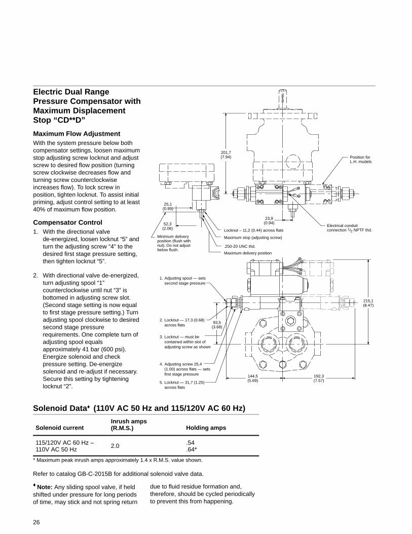
201,7(7.94) Position for
L.H. models
Electrical conduitconnection 1/2 NPTF thd.
23,9(0.94)
Locknut – 11,2 (0.44) across flats
Maximum stop (adjusting screw)
Maximum delivery position
.250-20 UNC thd.
215,1(8.47)
144,5(5.69)
192,3(7.57)
93,5(3.68)
Electric Dual RangePressure Compensator withMaximum DisplacementStop “CD**D”
Maximum Flow AdjustmentWith the system pressure below bothcompensator settings, loosen maximumstop adjusting screw locknut and adjustscrew to desired flow position (turningscrew clockwise decreases flow andturning screw counterclockwiseincreases flow). To lock screw inposition, tighten locknut. To assist initialpriming, adjust control setting to at least40% of maximum flow position.
Compensator Control1. With the directional valve
de-energized, loosen locknut “5” andturn the adjusting screw “4” to thedesired first stage pressure setting,then tighten locknut “5”.
2. With directional valve de-energized,turn adjusting spool “1”counterclockwise until nut “3” isbottomed in adjusting screw slot.(Second stage setting is now equalto first stage pressure setting.) Turnadjusting spool clockwise to desiredsecond stage pressurerequirements. One complete turn ofadjusting spool equalsapproximately 41 bar (600 psi).Energize solenoid and checkpressure setting. De-energizesolenoid and re-adjust if necessary.Secure this setting by tighteninglocknut “2”.
1. Adjusting spool — setssecond stage pressure
2. Locknut — 17,3 (0.68)across flats
3. Locknut — must becontained within slot ofadjusting screw as shown
4. Adjusting screw 25,4(1.00) across flats — setsfirst stage pressure
5. Locknut — 31,7 (1.25)across flats
Minimum deliveryposition (flush withnut). Do not adjustbelow flush.
52,3(2.06)
25,1(0.99)
26
Solenoid Data♦ (110V AC 50 Hz and 115/120V AC 60 Hz)
Solenoid currentInrush amps(R.M.S.) Holding amps
115/120V AC 60 Hz –110V AC 50 Hz
2.0 .54.64*
* Maximum peak inrush amps approximately 1.4 x R.M.S. value shown.
Refer to catalog GB-C-2015B for additional solenoid valve data.
♦ Note: Any sliding spool valve, if heldshifted under pressure for long periodsof time, may stick and not spring return
due to fluid residue formation and,therefore, should be cycled periodicallyto prevent this from happening.
27
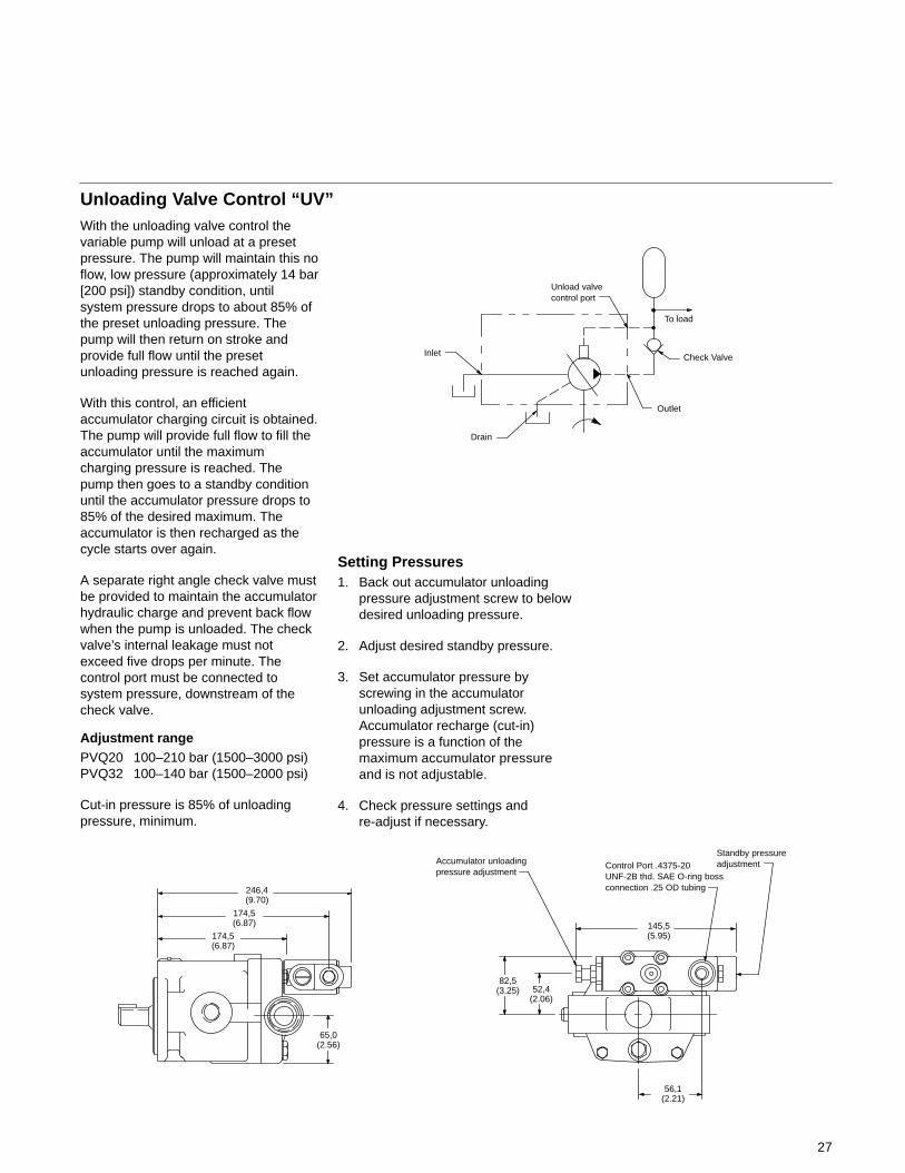
With the unloading valve control thevariable pump will unload at a presetpressure. The pump will maintain this noflow, low pressure (approximately 14 bar[200 psi]) standby condition, untilsystem pressure drops to about 85% ofthe preset unloading pressure. Thepump will then return on stroke andprovide full flow until the presetunloading pressure is reached again.
With this control, an efficientaccumulator charging circuit is obtained.The pump will provide full flow to fill theaccumulator until the maximumcharging pressure is reached. Thepump then goes to a standby conditionuntil the accumulator pressure drops to85% of the desired maximum. Theaccumulator is then recharged as thecycle starts over again.
A separate right angle check valve mustbe provided to maintain the accumulatorhydraulic charge and prevent back flowwhen the pump is unloaded. The checkvalve’s internal leakage must notexceed five drops per minute. Thecontrol port must be connected tosystem pressure, downstream of thecheck valve.
Adjustment rangePVQ20 100–210 bar (1500–3000 psi)PVQ32 100–140 bar (1500–2000 psi)
Cut-in pressure is 85% of unloadingpressure, minimum.
Setting Pressures1. Back out accumulator unloading
pressure adjustment screw to belowdesired unloading pressure.
2. Adjust desired standby pressure.
3. Set accumulator pressure byscrewing in the accumulatorunloading adjustment screw.Accumulator recharge (cut-in)pressure is a function of themaximum accumulator pressureand is not adjustable.
4. Check pressure settings andre-adjust if necessary.
Outlet
Drain
Inlet Check Valve
To load
Unload valvecontrol port
174,5(6.87)
65,0(2.56)
Accumulator unloadingpressure adjustment
Control Port .4375-20UNF-2B thd. SAE O-ring bossconnection .25 OD tubing
56,1(2.21)
246,4(9.70)
145,5(5.95)
82,5(3.25) 52,4
(2.06)
Standby pressureadjustment
174,5(6.87)
Unloading Valve Control “UV”
28
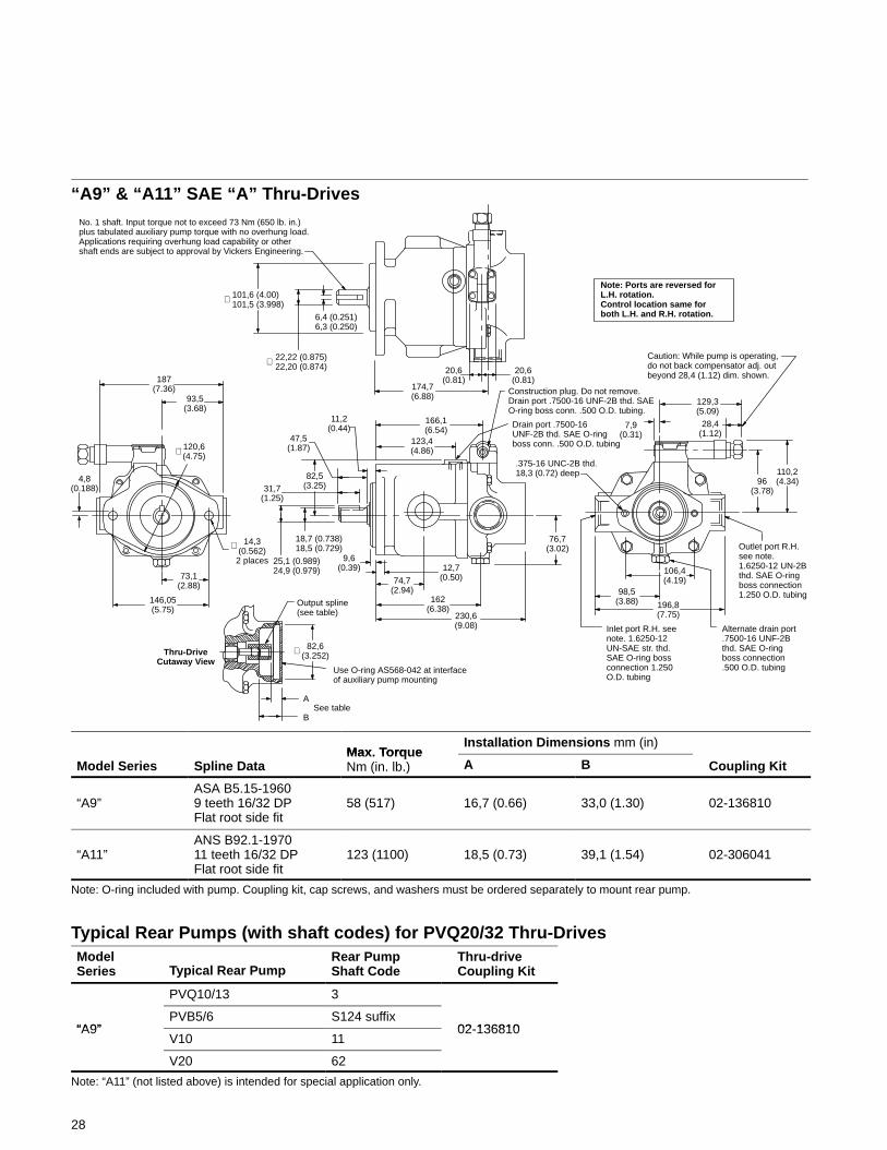
“A9” & “A11” SAE “A” Thru-Drives
187(7.36)
No. 1 shaft. Input torque not to exceed 73 Nm (650 lb. in.)plus tabulated auxiliary pump torque with no overhung load.Applications requiring overhung load capability or othershaft ends are subject to approval by Vickers Engineering.
101,6 (4.00)101,5 (3.998)∅
22,22 (0.875)22,20 (0.874)
6,4 (0.251)6,3 (0.250)
20,6(0.81)
174,7(6.88)
20,6(0.81)
∅
129,3(5.09)
28,4(1.12)
7,9(0.31)
110,2(4.34)96
(3.78)
.375-16 UNC-2B thd.18,3 (0.72) deep
Inlet port R.H. seenote. 1.6250-12UN-SAE str. thd.SAE O-ring bossconnection 1.250O.D. tubing
Alternate drain port.7500-16 UNF-2Bthd. SAE O-ringboss connection.500 O.D. tubing
106,4(4.19)
98,5(3.88) 196,8
(7.75)
Outlet port R.H.see note.1.6250-12 UN-2Bthd. SAE O-ringboss connection1.250 O.D. tubing
Construction plug. Do not remove.Drain port .7500-16 UNF-2B thd. SAEO-ring boss conn. .500 O.D. tubing.
76,7(3.02)
230,6(9.08)
162(6.38)
74,7(2.94)
12,7(0.50)
9,6(0.39)
166,1(6.54)
123,4(4.86)
11,2(0.44)
47,5(1.87)
82,5(3.25)31,7
(1.25)
18,7 (0.738)18,5 (0.729)
25,1 (0.989)24,9 (0.979)
Output spline(see table)
82,6(3.252)∅
A
BSee table
Use O-ring AS568-042 at interfaceof auxiliary pump mounting
93,5(3.68)
120,6(4.75)∅
14,3(0.562)
2 places
∅
146,05(5.75)
73,1(2.88)
4,8(0.188)
Drain port .7500-16UNF-2B thd. SAE O-ringboss conn. .500 O.D. tubing
Thru-DriveCutaway View
Note: Ports are reversed forL.H. rotation. Control location same forboth L.H. and R.H. rotation.
Caution: While pump is operating,do not back compensator adj. outbeyond 28,4 (1.12) dim. shown.
Max Torq eInstallation Dimensions mm (in)
Model Series Spline DataMax. TorqueNm (in. lb.) A B Coupling Kit
“A9”ASA B5.15-19609 teeth 16/32 DPFlat root side fit
58 (517) 16,7 (0.66) 33,0 (1.30) 02-136810
“A11”ANS B92.1-197011 teeth 16/32 DPFlat root side fit
123 (1100) 18,5 (0.73) 39,1 (1.54) 02-306041
Note: O-ring included with pump. Coupling kit, cap screws, and washers must be ordered separately to mount rear pump.
Typical Rear Pumps (with shaft codes) for PVQ20/32 Thru-DrivesModelSeries Typical Rear Pump
Rear PumpShaft Code
Thru-driveCoupling Kit
PVQ10/13 3
“A9”PVB5/6 S124 suffix
02 136810“A9”V10 11
02-136810
V20 62
Note: “A11” (not listed above) is intended for special application only.
29
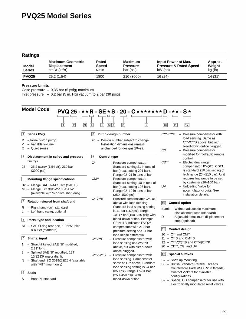
PVQ25 Model Series
Ratings
ModelSeries
Maximum GeometricDisplacementcm3/r (in3/r)
RatedSpeedr/min
MaximumPressurebar (psi)
Input Power at Max.Pressure & Rated SpeedkW (hp)
Approx.Weightkg (lb)
PVQ25 25,2 (1.54) 1800 210 (3000) 16 (24) 14 (31)
Pressure LimitsCase pressure – 0,35 bar (5 psig) maximumInlet pressure – 0,2 bar (5 in. Hg) vacuum to 2 bar (30 psig)
Pump design number
20 – Design number subject to change.Installation dimensions remainunchanged for designs 20–29.
Control type
C** – Pressure compensator.Standard setting 21 in tens ofbar (max. setting 201 bar).Range 02–21 in tens of bar.
CM** – Pressure compensator.Standard setting, 10 in tens ofbar (max. setting 103 bar).Range 02–10 in tens of bar(350–1500 psi).
C**V**B – Pressure compensator C**, asabove with load sensing.Standard load sensing settingis 11 bar (160 psi); range10–17 bar (150–250 psi); withbleed-down orifice. Example:C21V11B indicates PVQ25compensator with 210 barpressure setting and 11 barload-sense differential.
C**V**P – Pressure compensator withload sensing as C**V**Babove, but with bleed-downorifice plugged.
C**VC**B – Pressure compensator withload sensing. Compensatorsame as C** above. Standardload sensing setting is 24 bar(350 psi), range 17–31 bar(250–450 psi). Withbleed-down orifice.
3 4 5 876 9 101 2 11
Model Code
1
2
Series PVQ
P – Inline piston pumpV – Variable volumeQ – Quiet series
Displacement in cc/rev and pressureratings
25 – 25,2 cc/rev (1.54 cir), 210 bar(3000 psi)
Mounting flange specifications
B2 – Flange SAE J744 101-2 (SAE B)MB – Flange ISO 3019/2-100A2HW
(available with “N” drive shaft only)
Rotation viewed from shaft end
R – Right hand (cw), standardL – Left hand (ccw), optional
Ports, type and location
SE – SAE O-ring rear port, 1.0625” inlet& outlet (standard)
Shafts, input
1 – Straight keyed SAE “B” modified,2.31” long
3 – Splined SAE “B” modified, 13T16/32 DP major dia. fit
N – Shaft end ISO 3019/2 E25N (availablewith “MB” mount only)
Seals
S – Buna N, standard
3
4
5
6
7
8
9
11
10
C**VC**P – Pressure compensator withload sensing. Same asC**VC**B above, but withbleed-down orifice plugged.
CG – Pressure compensatormodified for hydraulic remotecontrol.
CD** – Electric dual rangecompensator. PVQ25: CD21is standard 210 bar setting ofhigh range (24–210 bar). Unitrequires low range to be setby customer (20–100 bar).
UV – Unloading Valve foraccumulator circuits. Seeinstallation details.
Control option
Blank – Without adjustable maximumdisplacement stop (standard)
D – Adjustable maximum displacementstop (optional)
Control design
10 – C** and CM**11 – C**D and CM**D12 – C**V(C)**B and C**V(C)**P20 – CD**, CG, and UV
Special suffixes
S2 – Shaft up mountingS3 – British Standard Parallel Threads
Counterbore Ports (ISO R288 threads).Contact Vickers for availableconfigurations.
S9 – Special CG compensator for use withelectronically modulated relief valves
12
12
30
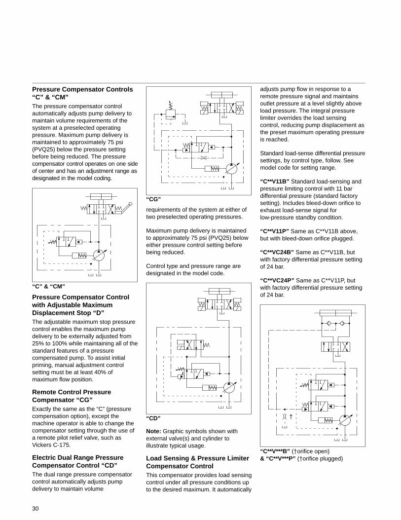
Pressure Compensator Controls“C” & “CM”The pressure compensator controlautomatically adjusts pump delivery tomaintain volume requirements of thesystem at a preselected operatingpressure. Maximum pump delivery ismaintained to approximately 75 psi(PVQ25) below the pressure settingbefore being reduced. The pressurecompensator control operates on one sideof center and has an adjustment range asdesignated in the model coding.
“C” & “CM”
Pressure Compensator Controlwith Adjustable MaximumDisplacement Stop “D”The adjustable maximum stop pressurecontrol enables the maximum pumpdelivery to be externally adjusted from25% to 100% while maintaining all of thestandard features of a pressurecompensated pump. To assist initialpriming, manual adjustment controlsetting must be at least 40% ofmaximum flow position.
Remote Control PressureCompensator “CG”Exactly the same as the “C” (pressurecompensation option), except themachine operator is able to change thecompensator setting through the use ofa remote pilot relief valve, such asVickers C-175.
Electric Dual Range PressureCompensator Control “CD”The dual range pressure compensatorcontrol automatically adjusts pumpdelivery to maintain volume
“CG”
requirements of the system at either oftwo preselected operating pressures.
Maximum pump delivery is maintainedto approximately 75 psi (PVQ25) beloweither pressure control setting beforebeing reduced.
Control type and pressure range aredesignated in the model code.
“CD”
Note: Graphic symbols shown withexternal valve(s) and cylinder toillustrate typical usage.
Load Sensing & Pressure LimiterCompensator ControlThis compensator provides load sensingcontrol under all pressure conditions upto the desired maximum. It automatically
adjusts pump flow in response to aremote pressure signal and maintainsoutlet pressure at a level slightly aboveload pressure. The integral pressurelimiter overrides the load sensingcontrol, reducing pump displacement asthe preset maximum operating pressureis reached.
Standard load-sense differential pressuresettings, by control type, follow. Seemodel code for setting range.
“C**V11B” Standard load-sensing andpressure limiting control with 11 bardifferential pressure (standard factorysetting). Includes bleed-down orifice toexhaust load-sense signal forlow-pressure standby condition.
“C**V11P” Same as C**V11B above,but with bleed-down orifice plugged.
“C**VC24B” Same as C**V11B, butwith factory differential pressure settingof 24 bar.
“C**VC24P” Same as C**V11P, butwith factory differential pressure settingof 24 bar.
“C**V***B” (�orifice open)& “C**V***P” (�orifice plugged)
�
31
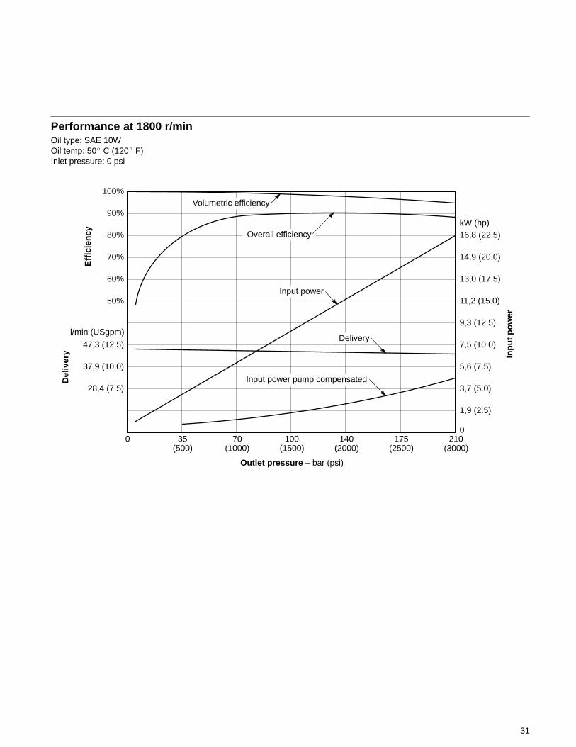
Performance at 1800 r/minOil type: SAE 10WOil temp: 50� C (120� F)Inlet pressure: 0 psi
100%
90%
80%
70%
60%
50%
47,3 (12.5)
37,9 (10.0)
28,4 (7.5)
Eff
icie
ncy
l/min (USgpm)
Del
iver
y
16,8 (22.5)
14,9 (20.0)
13,0 (17.5)
11,2 (15.0)
9,3 (12.5)
7,5 (10.0)
5,6 (7.5)
3,7 (5.0)
1,9 (2.5)
0
Inp
ut
po
wer
21017514010070350(3000)(2500)(2000)(1500)(1000)(500)
Outlet pressure – bar (psi)
kW (hp)
Volumetric efficiency
Overall efficiency
Input power
Input power pump compensated
Delivery
32
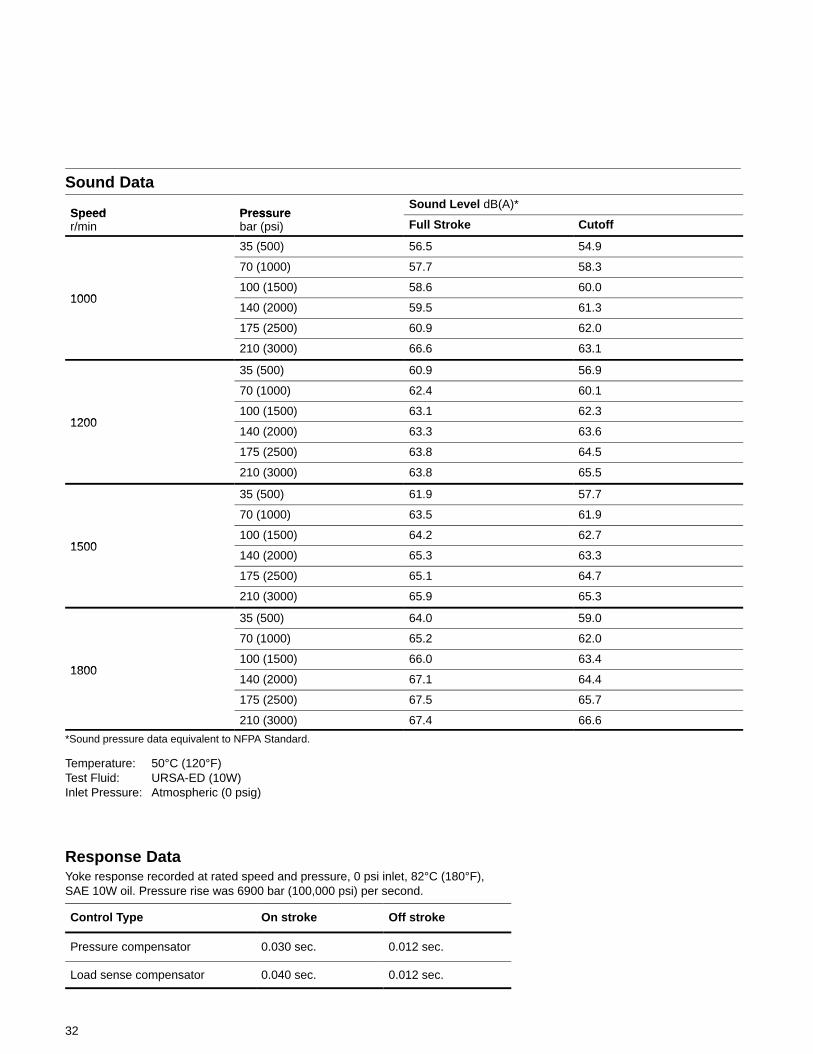
Sound Data
Speed Press reSound Level dB(A)*
Speedr/min
Pressurebar (psi) Full Stroke Cutoff
35 (500) 56.5 54.9
70 (1000) 57.7 58.3
1000100 (1500) 58.6 60.0
1000140 (2000) 59.5 61.3
175 (2500) 60.9 62.0
210 (3000) 66.6 63.1
35 (500) 60.9 56.9
70 (1000) 62.4 60.1
1200100 (1500) 63.1 62.3
1200140 (2000) 63.3 63.6
175 (2500) 63.8 64.5
210 (3000) 63.8 65.5
35 (500) 61.9 57.7
70 (1000) 63.5 61.9
1500100 (1500) 64.2 62.7
1500140 (2000) 65.3 63.3
175 (2500) 65.1 64.7
210 (3000) 65.9 65.3
35 (500) 64.0 59.0
70 (1000) 65.2 62.0
1800100 (1500) 66.0 63.4
1800140 (2000) 67.1 64.4
175 (2500) 67.5 65.7
210 (3000) 67.4 66.6
*Sound pressure data equivalent to NFPA Standard.
Temperature: 50°C (120°F)Test Fluid: URSA-ED (10W)Inlet Pressure: Atmospheric (0 psig)
Response DataYoke response recorded at rated speed and pressure, 0 psi inlet, 82°C (180°F),SAE 10W oil. Pressure rise was 6900 bar (100,000 psi) per second.
Control Type On stroke Off stroke
Pressure compensator 0.030 sec. 0.012 sec.
Load sense compensator 0.040 sec. 0.012 sec.
33
Pressure CompensatorControl with AdjustableMax. Displacement Stop “D”
AdjustmentLoosen locknut on adjusting rod. Turnadjusting rod clockwise (CW) todecrease maximum pump delivery orcounterclockwise (CCW) to increasemaximum pump delivery until desiredsetting is obtained. Secure this settingby tightening locknut.
Remote Compensator “CG”
Adjustment1. Turn pressure control (such as C-175)
CCW to minimum setting.
2. Turn compensator adjustment plug todesired minimum pressure (17 bar,250 psi or higher).
3. Full pressure range can now beobtained with pressure control.
Caution:Effective compensator pressure will beCG compensator control setting (17–69bar, 250–1000 psig) plus remote reliefvalve setting.
Load Sensing with Pressure Limiter “C**V****”
72,6(2.86)
52,0(2.05)
90,1(3.55)
Locknut11,2 (0.44) across flats
28,4(1.12)
∅
63,8(2.51)
28,4(1.12)
Adjusting screw23,8 (0.90) across flats
123,8(4.87)
30,0(1.18)
11,0(0.43)
252,1(9.93)
220,2(8.67)196,2
(7.72)
Dimensionsto flange face
Control position forright hand rotation
Control position forleft hand rotation
Maximum stopadjusting rod
(Approx. 2.22 cc/revchange per turn)
Max.
Load sensing control portlocation for L.H. rotation
To mounting faceof pump mtg. flg.
Load sensing comp. controlport location for R.H.rotation .4375-20 UNF-2Bboss connection
190,75(7.51)
167,39(6.59)
28,45(1.12)Max.
Compensator adj. knob.Do not back out adj. knobbeyond 28,4 (1.12) dim.shown while pump isoperating.
28,45(1.12)
D
19,05(0.75)
45,1(1.775)
Do not operate pumpwith this port plugged.
.4375-20 UNF-2Bthread for “CG”control models.
Connect to pressurecontrol, such as
C-175. SAE O-ringboss connection.250 O.D. tubing
Electric Dual RangePressure CompensatorControl “CD”
Adjustment1. With the directional valve
de-energized, loosen locknut “5” andturn the adjusting screw “4” to thedesired first stage pressure setting,then tighten locknut “5”.
2. With solenoid de-energized, turnadjusting spool “1” counterclockwise(CCW) until nut “3” is bottomed inadjusting screw slot. (Second stagesetting is now equal to first stagepressure setting.) Turn adjustingspool clockwise (CW) to desiredsecond stage pressurerequirements. One complete turn ofadjusting spool equalsapproximately 41 bar (600 psi).Energize solenoid and checkpressure setting. De-energizesolenoid and re-adjust if necessary.Secure this setting by tighteninglocknut “2”.
1. Adjusting spool — setssecond stage pressure
312,1(12.29)
186,6(7.35)
Position forR.H. models
Electrical conduitconn. 1/2 NPTF thd.
Dual range pressurecompensator position
52,0(2.05)
2. Locknut — 17,3 (0.68)across flats
3. Locknut — must becontained within slot ofadjusting screw as shown
4. Adjusting screw 25,4(1.00) across flats — setsfirst stage pressure
5. Locknut — 31,7 (1.25)across flats
126,6(4.98)
Dimension fromflange face
34
Solenoid Data♦ (110V AC 50 Hz and 115/120V AC 60 Hz)
Solenoid currentInrush amps(R.M.S.) Holding amps
115/120V AC 60 Hz –110V AC 50 Hz
2.0 .54.64*
* Maximum peak inrush amps approximately 1.4 x R.M.S. value shown.
Refer to catalog GB-C-2015B for additional solenoid valve data.
♦ Note: Any sliding spool valve, if heldshifted under pressure for long periodsof time, may stick and not spring returndue to fluid residue formation and,therefore, should be cycled periodicallyto prevent this from happening.
196,2(7.72) Position for
L.H. models
Electrical conduitconnection 1/2 NPTF thd.
30,0(1.18)
Minimum deliveryposition (flush withnut). Do not adjustbelow flush.
52,3(2.06)
25,1(0.99)
Locknut – 11,2 (0.44) across flats
Maximum stop (adjusting screw)
Maximum delivery position
.250-20 UNC thd.
213,4(8.40)
136,3(5.37)
196,3(7.73)
93,5(3.68)
Electric Dual RangePressure Compensator withMaximum DisplacementStop “CD**D”
Maximum Flow AdjustmentWith the system pressure below bothcompensator settings, loosen maximumstop adjusting screw locknut and adjustscrew to desired flow position (turningscrew clockwise decreases flow andturning screw counterclockwiseincreases flow). To lock screw inposition, tighten locknut. To assist initialpriming, adjust control setting to at least40% of maximum flow position.
Compensator Control1. With the directional valve
de-energized, loosen locknut “5” andturn the adjusting screw “4” to thedesired first stage pressure setting,then tighten locknut “5”.
2. With directional valve de-energized,turn adjusting spool “1”counterclockwise until nut “3” isbottomed in adjusting screw slot.(Second stage setting is now equalto first stage pressure setting.) Turnadjusting spool clockwise to desiredsecond stage pressurerequirements. One complete turn ofadjusting spool equalsapproximately 41 bar (600 psi).Energize solenoid and checkpressure setting. De-energizesolenoid and re-adjust if necessary.Secure this setting by tighteninglocknut “2”.
1. Adjusting spool — setssecond stage pressure
2. Locknut — 17,3 (0.68)across flats
3. Locknut — must becontained within slot ofadjusting screw as shown
4. Adjusting screw 25,4(1.00) across flats — setsfirst stage pressure
5. Locknut — 31,7 (1.25)across flats
Dimension fromflange face
Maximum stopadjusting rod(Approx. 2.22 cc/revchange per turn)
35
Solenoid Data♦ (110V AC 50 Hz and 115/120V AC 60 Hz)
Solenoid currentInrush amps(R.M.S.) Holding amps
115/120V AC 60 Hz –110V AC 50 Hz
2.0 .54.64*
* Maximum peak inrush amps approximately 1.4 x R.M.S. value shown.
Refer to catalog GB-C-2015B for additional solenoid valve data.
♦ Note: Any sliding spool valve, if heldshifted under pressure for long periodsof time, may stick and not spring return
due to fluid residue formation and,therefore, should be cycled periodicallyto prevent this from happening.
36
With the unloading valve control thevariable pump will unload at a presetpressure. The pump will maintain this noflow, low pressure (approximately 14 bar[200 psi]) standby condition, untilsystem pressure drops to about 85% ofthe preset unloading pressure. Thepump will then return on stroke andprovide full flow until the presetunloading pressure is reached again.
With this control, an efficientaccumulator charging circuit is obtained.The pump will provide full flow to fill theaccumulator until the maximumcharging pressure is reached. Thepump then goes to a standby conditionuntil the accumulator pressure drops to85% of the desired maximum. Theaccumulator is then recharged as thecycle starts over again.
A separate right angle check valve mustbe provided to maintain the accumulatorhydraulic charge and prevent back flowwhen the pump is unloaded. The checkvalve’s internal leakage must notexceed five drops per minute. Thecontrol port must be connected tosystem pressure, downstream of thecheck valve.
Adjustment rangePVQ25 100–210 bar (1500–3000 psi)
Cut-in pressure is 85% of unloadingpressure, minimum.
Setting Pressures1. Back out accumulator unloading
pressure adjustment screw to belowdesired unloading pressure.
2. Adjust desired standby pressure.
3. Set accumulator pressure byscrewing in the accumulatorunloading adjustment screw.Accumulator recharge (cut-in)pressure is a function of themaximum accumulator pressureand is not adjustable.
4. Check pressure settings andre-adjust if necessary.
Outlet
Drain
Inlet Check Valve
To load
Unload valvecontrol port
162,5(6.40)
196,6(7.74)
272,8(10.74)
167,5(6.59)
41,1(1.62)
145,5(5.95)
52,0(2.05)
Standby pressureadjustment
Control Port .4375-20UNF-2B thd. SAE O-ring bossconnection .25 OD tubing
Accumulator unloadingpressure adjustment
Unloading Valve Control “UV”
37
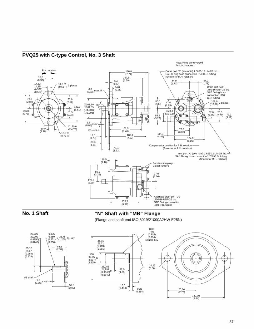
47,0(1.85)
52,0(2.05)
14,5314,15(0.572)(0.557)
PVQ25 with C-type Control, No. 3 Shaft
77,0(3.03)
58,6(2.31)
27,0(1.06)
Alternate drain port “D1”.750-16 UNF-2B thd.SAE O-ring connection.500 O.D. tubing
50.8(2.00)
#1 shaft1.5
(0.06)
25,1224,87
(0.989)(0.979)
22,22522,200
(0.8750)(0.8740)
6,3756,350
(0.251)(0.250)
lg. key
146,0(5.75)
73,0(2.87)
30,0(1.18)
19,5 R(0.77 R)
∅ 120,6(∅ 4.75)
140,0(5.51)
51,5(2.03)
70,0(2.76)
14,0 R(0.55 R) 2 places
R.H. rotation
186,1(7.33)
162,5(6.40)
14,0(0.55)
9.4(0.37)
167,5(6.59)
196,6(7.74)
0,8(0.03) max. R
∅ 101,60∅ 101.55(∅ 4.000)(∅ 3.998)
30�
1.5(0.06) x 45�
#2 shaft
41,1(1.62)
33,3(1.31)
19,0(0.75)
29,5(1.16)
85,1(3.35)
170,2(6.70)
154,0(6.06)
114,1(4.49)
83,1(3.27)
60,0(2.36)
44,0(1.73)
79,2(3.12)
70,0(2.76)
∅ 28,4(∅ 1.12)
∅ 56,0(∅ 2.20) 2 places
25,0(0.98)
153,5(6.04)
Construction plugsDo not remove
Compensator position for R.H. rotation(Reverse for L.H. rotation)
Drain port “D2”.750-16 UNF-2B thd.SAE O-ring bossconnection .500O.D. tubing
Outlet port “B” (see note) 1.0625-12 UN-2B thd.SAE O-ring boss connection .750 O.D. tubing(Shown for R.H. rotation)
44,0(1.73)
Inlet port “A” (see note) 1.625-12 UN-2B thd.SAE O-ring boss connection 1.250 O.D. tubing
(Shown for R.H. rotation)
x 45�
31,75(1.250)x
Note: Ports are reversedfor L.H. rotation.
No. 1 Shaft “N” Shaft with “MB” Flange(Flange and shaft end ISO 3019/21000A2HW-E25N)
10099,95
(3.937)(3.935)
28,0127,71
(1.103)(1.091)
D
25,00624,994
(0.9845)(0.9840)
D 42,0(1.65)
10,5(0.413) 9,25
(0.364)
8,007,96
(0.315)(0.314)
Square key
140,00(5.51)
70,00(2.76)
14,25(0.56)
38
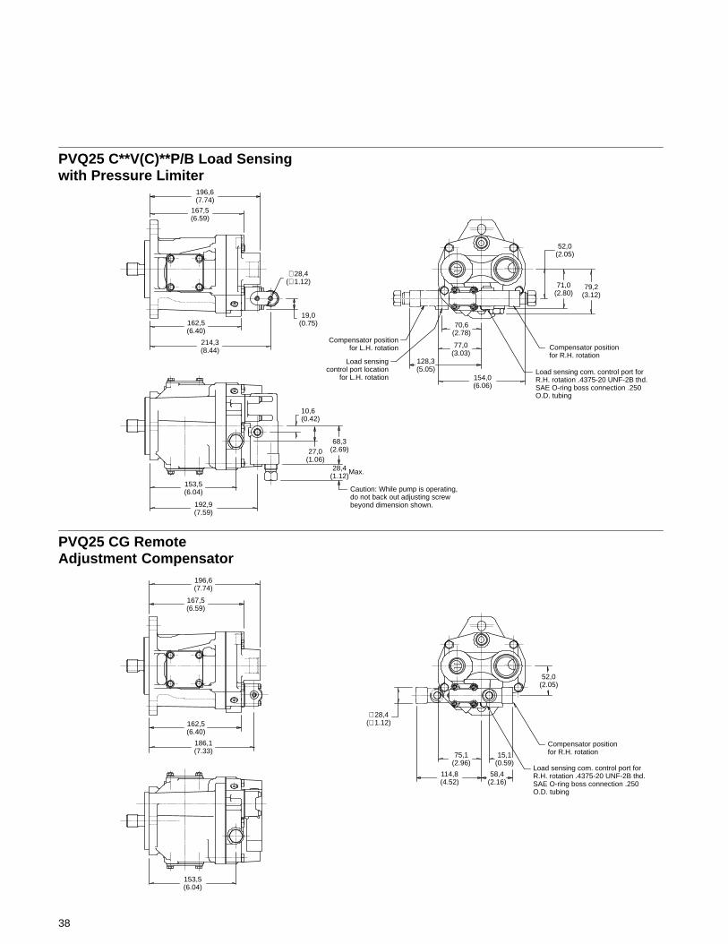
15,1(0.59)
58,4(2.16)
128,3(5.05)
68,3(2.69)
162,5(6.40)
PVQ25 C**V(C)**P/B Load Sensingwith Pressure Limiter
196,6(7.74)
∅ 28,4(∅ 1.12)
19,0(0.75)
214,3(8.44)
167,5(6.59)
153,5(6.04)
192,9(7.59)
10,6(0.42)
27,0(1.06)
Compensator positionfor L.H. rotation
52,0(2.05)
71,0(2.80)
79,2(3.12)
Compensator positionfor R.H. rotation
Load sensing com. control port forR.H. rotation .4375-20 UNF-2B thd.SAE O-ring boss connection .250O.D. tubing
Load sensingcontrol port location
for L.H. rotation 154,0(6.06)
77,0(3.03)
70,6(2.78)
52,0(2.05)
Compensator positionfor R.H. rotation
Load sensing com. control port forR.H. rotation .4375-20 UNF-2B thd.SAE O-ring boss connection .250O.D. tubing
75,1(2.96)
PVQ25 CG RemoteAdjustment Compensator
114,8(4.52)
∅ 28,4(∅ 1.12)
186,1(7.33)
162,5(6.40)
167,5(6.59)
196,6(7.74)
153,5(6.04)
28,4(1.12)
Max.
Caution: While pump is operating,do not back out adjusting screwbeyond dimension shown.
Note: Integral relief valve limits case pressure peaks to 0,7 bar (10 psi) higherthan inlet pressure to protect pump. Flow from valve is returned directly to pumpinlet. Use of case drain line required to limit steady-state case pressure.
39
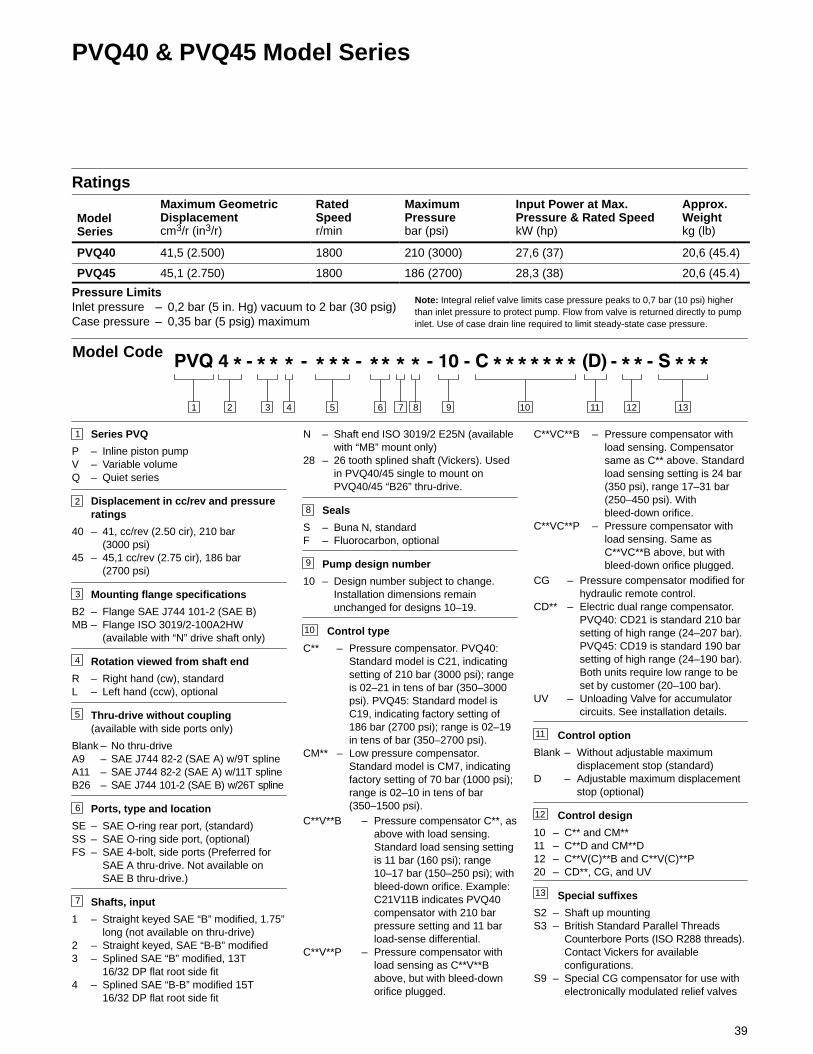
PVQ40 & PVQ45 Model Series
Ratings
ModelSeries
Maximum GeometricDisplacementcm3/r (in3/r)
RatedSpeedr/min
MaximumPressurebar (psi)
Input Power at Max.Pressure & Rated SpeedkW (hp)
Approx.Weightkg (lb)
PVQ40 41,5 (2.500) 1800 210 (3000) 27,6 (37) 20,6 (45.4)
PVQ45 45,1 (2.750) 1800 186 (2700) 28,3 (38) 20,6 (45.4)
Pressure LimitsInlet pressure – 0,2 bar (5 in. Hg) vacuum to 2 bar (30 psig)Case pressure – 0,35 bar (5 psig) maximum
3 4 5 876 9 101 2 11
Model Code
1
2
Series PVQ
P – Inline piston pumpV – Variable volumeQ – Quiet series
Displacement in cc/rev and pressureratings
40 – 41, cc/rev (2.50 cir), 210 bar(3000 psi)
45 – 45,1 cc/rev (2.75 cir), 186 bar(2700 psi)
Mounting flange specifications
B2 – Flange SAE J744 101-2 (SAE B)MB – Flange ISO 3019/2-100A2HW
(available with “N” drive shaft only)
Rotation viewed from shaft end
R – Right hand (cw), standardL – Left hand (ccw), optional
Thru-drive without coupling(available with side ports only)
Blank – No thru-driveA9 – SAE J744 82-2 (SAE A) w/9T splineA11 – SAE J744 82-2 (SAE A) w/11T splineB26 – SAE J744 101-2 (SAE B) w/26T spline
Ports, type and location
SE – SAE O-ring rear port, (standard)SS – SAE O-ring side port, (optional)FS – SAE 4-bolt, side ports (Preferred for
SAE A thru-drive. Not available onSAE B thru-drive.)
Shafts, input
1 – Straight keyed SAE “B” modified, 1.75”long (not available on thru-drive)
2 – Straight keyed, SAE “B-B” modified3 – Splined SAE “B” modified, 13T
16/32 DP flat root side fit4 – Splined SAE “B-B” modified 15T
16/32 DP flat root side fit
3
4
5
6
7
8
9
11
10
N – Shaft end ISO 3019/2 E25N (availablewith “MB” mount only)
28 – 26 tooth splined shaft (Vickers). Usedin PVQ40/45 single to mount onPVQ40/45 “B26” thru-drive.
Seals
S – Buna N, standardF – Fluorocarbon, optional
Pump design number
10 – Design number subject to change.Installation dimensions remainunchanged for designs 10–19.
Control type
C** – Pressure compensator. PVQ40:Standard model is C21, indicatingsetting of 210 bar (3000 psi); rangeis 02–21 in tens of bar (350–3000psi). PVQ45: Standard model isC19, indicating factory setting of186 bar (2700 psi); range is 02–19in tens of bar (350–2700 psi).
CM** – Low pressure compensator.Standard model is CM7, indicatingfactory setting of 70 bar (1000 psi);range is 02–10 in tens of bar(350–1500 psi).
C**V**B – Pressure compensator C**, asabove with load sensing.Standard load sensing settingis 11 bar (160 psi); range10–17 bar (150–250 psi); withbleed-down orifice. Example:C21V11B indicates PVQ40compensator with 210 barpressure setting and 11 barload-sense differential.
C**V**P – Pressure compensator withload sensing as C**V**Babove, but with bleed-downorifice plugged.
C**VC**B – Pressure compensator withload sensing. Compensatorsame as C** above. Standardload sensing setting is 24 bar(350 psi), range 17–31 bar(250–450 psi). Withbleed-down orifice.
C**VC**P – Pressure compensator withload sensing. Same asC**VC**B above, but withbleed-down orifice plugged.
CG – Pressure compensator modified forhydraulic remote control.
CD** – Electric dual range compensator.PVQ40: CD21 is standard 210 barsetting of high range (24–207 bar).PVQ45: CD19 is standard 190 barsetting of high range (24–190 bar).Both units require low range to beset by customer (20–100 bar).
UV – Unloading Valve for accumulatorcircuits. See installation details.
Control option
Blank – Without adjustable maximumdisplacement stop (standard)
D – Adjustable maximum displacementstop (optional)
Control design
10 – C** and CM**11 – C**D and CM**D12 – C**V(C)**B and C**V(C)**P20 – CD**, CG, and UV
Special suffixes
S2 – Shaft up mountingS3 – British Standard Parallel Threads
Counterbore Ports (ISO R288 threads).Contact Vickers for availableconfigurations.
S9 – Special CG compensator for use withelectronically modulated relief valves
12
12
13
13
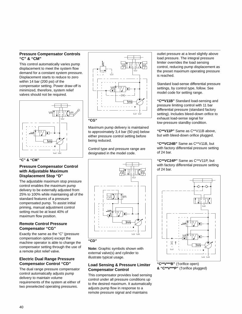
40
Pressure Compensator Controls“C” & “CM”This control automatically varies pumpdisplacement to meet the system flowdemand for a constant system pressure.Displacement starts to reduce to zerowithin 14 bar (200 psi) of thecompensator setting. Power draw-off isminimized, therefore, system reliefvalves should not be required.
“C” & “CM”
Pressure Compensator Controlwith Adjustable MaximumDisplacement Stop “D”The adjustable maximum stop pressurecontrol enables the maximum pumpdelivery to be externally adjusted from25% to 100% while maintaining all of thestandard features of a pressurecompensated pump. To assist initialpriming, manual adjustment controlsetting must be at least 40% ofmaximum flow position.
Remote Control PressureCompensator “CG”Exactly the same as the “C” (pressurecompensation option) except themachine operator is able to change thecompensator setting through the use ofa remote pilot relief valve.
Electric Dual Range PressureCompensator Control “CD”The dual range pressure compensatorcontrol automatically adjusts pumpdelivery to maintain volumerequirements of the system at either oftwo preselected operating pressures.
“CG”
Maximum pump delivery is maintainedto approximately 3,4 bar (50 psi) beloweither pressure control setting beforebeing reduced.
Control type and pressure range aredesignated in the model code.
“CD”
Note: Graphic symbols shown withexternal valve(s) and cylinder toillustrate typical usage.
Load Sensing & Pressure LimiterCompensator ControlThis compensator provides load sensingcontrol under all pressure conditions upto the desired maximum. It automaticallyadjusts pump flow in response to aremote pressure signal and maintains
outlet pressure at a level slightly aboveload pressure. The integral pressurelimiter overrides the load sensingcontrol, reducing pump displacement asthe preset maximum operating pressureis reached.
Standard load-sense differential pressuresettings, by control type, follow. Seemodel code for setting range.
“C**V11B” Standard load-sensing andpressure limiting control with 11 bardifferential pressure (standard factorysetting). Includes bleed-down orifice toexhaust load-sense signal forlow-pressure standby condition.
“C**V11P” Same as C**V11B above,but with bleed-down orifice plugged.
“C**VC24B” Same as C**V11B, butwith factory differential pressure settingof 24 bar.
“C**VC24P” Same as C**V11P, butwith factory differential pressure settingof 24 bar.
“C**V***B” (�orifice open)& “C**V***P” (�orifice plugged)
�
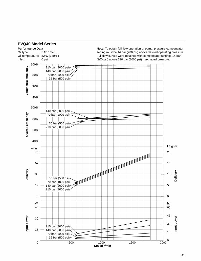
41
PVQ40 Model SeriesPerformance DataOil type: SAE 10WOil temperature: 82°C (180°F)Inlet: 0 psi
Speed r/min0 500 1000 1500 2000
15
30
45
0
5
10
15
20
kW
USgpm
Note: To obtain full flow operation of pump, pressure compensatorsetting must be 14 bar (200 psi) above desired operating pressure.Full flow curves were obtained with compensator settings 14 bar(200 psi) above 210 bar (3000 psi) max. rated pressure.
40%
60%
80%
100%
Volu
met
ric
effi
cien
cy
40%
60%
80%
100%
Ove
rall
effi
cien
cyD
eliv
ery
76
0
19
38
57
l/min
Del
iver
y
hp
Inp
ut
po
wer
0
15
30
45
60
Inp
ut
po
wer
210 bar (3000 psi)140 bar (2000 psi)70 bar (1000 psi)
35 bar (500 psi)
210 bar (3000 psi)140 bar (2000 psi)
35 bar (500 psi)
210 bar (3000 psi)140 bar (2000 psi)70 bar (1000 psi)
35 bar (500 psi)
35 bar (500 psi)210 bar (3000 psi)
70 bar (1000 psi)140 bar (2000 psi)
70 bar (1000 psi)
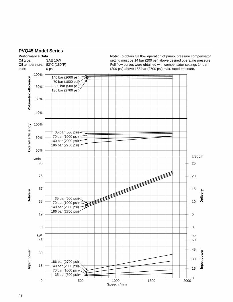
42
PVQ45 Model SeriesPerformance DataOil type: SAE 10WOil temperature: 82°C (180°F)Inlet: 0 psi
Speed r/min0 500 1000 1500 2000
15
30
45
0
5
10
15
20
kW
Note: To obtain full flow operation of pump, pressure compensatorsetting must be 14 bar (200 psi) above desired operating pressure.Full flow curves were obtained with compensator settings 14 bar(200 psi) above 186 bar (2700 psi) max. rated pressure.
40%
60%
80%
100%
Volu
met
ric
effi
cien
cy
60%
80%
100%
Ove
rall
effi
cien
cyD
eliv
ery
76
0
19
38
57
Del
iver
y
hp
Inp
ut
po
wer
0
15
30
45
60
Inp
ut
po
wer
140 bar (2000 psi)70 bar (1000 psi)
35 bar (500 psi)186 bar (2700 psi)
186 bar (2700 psi)
186 bar (2700 psi)140 bar (2000 psi)70 bar (1000 psi)
35 bar (500 psi)
140 bar (2000 psi)70 bar (1000 psi)
35 bar (500 psi)
140 bar (2000 psi)186 bar (2700 psi)
35 bar (500 psi)
95l/min
25
USgpm
70 bar (1000 psi)
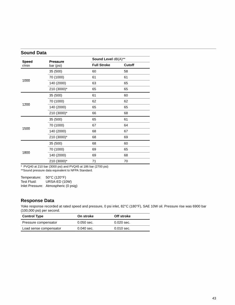
43
Sound Data
Speed Press reSound Level dB(A)**
Speedr/min
Pressurebar (psi) Full Stroke Cutoff
35 (500) 60 58
100070 (1000) 61 61
1000140 (2000) 63 65
210 (3000)* 65 65
35 (500) 61 60
120070 (1000) 62 62
1200140 (2000) 65 65
210 (3000)* 66 68
35 (500) 65 61
150070 (1000) 67 64
1500140 (2000) 68 67
210 (3000)* 68 69
35 (500) 68 60
180070 (1000) 69 65
1800140 (2000) 69 68
210 (3000)* 71 70
* PVQ40 at 210 bar (3000 psi) and PVQ45 at 186 bar (2700 psi)**Sound pressure data equivalent to NFPA Standard.
Temperature: 50°C (120°F)Test Fluid: URSA-ED (10W)Inlet Pressure: Atmospheric (0 psig)
Response DataYoke response recorded at rated speed and pressure, 0 psi inlet, 82°C (180°F), SAE 10W oil. Pressure rise was 6900 bar(100,000 psi) per second.
Control Type On stroke Off stroke
Pressure compensator 0.050 sec. 0.020 sec.
Load sense compensator 0.040 sec. 0.010 sec.

44
Side Ports, “C” & “CM” Controls, No. 2 ShaftInstallation dimensions in mm (inches)
191,00(7.52)
Outlet port “B” see note.1.3125-12 UN-2B thd. SAEO-ring boss connection1.000 O.D. tubing. Shownfor R.H. rotation.41,56
(1.64) Construction plug.Do not remove.
Drain port “D1” .875-14 UNF-2B thd. SAEO-ring boss connection .625 O.D. tubing
97,28(3.83)
194,56(7.66)
25,37 (0.999)25,35 (0.998)∅
14,22(0.56)
176,28(6.94)
Inlet port “A” see note.1.875–12 UN–2B thd. SAEO-ring boss connection1.500 O.D. tubing. Shownfor R.H. rotation
25,45(1.12)
95,25(3.75)
50,04(1.97)
190,5(7.50)
25,4(1.00)
118,11(4.65)
173,74(6.84)
86,87(3.42)
93,2(3.67)
91,44(3.60)
98,30(3.87)
196,60(7.74)
52,83(2.08)∅
Alternate drain port “D2”.875-14 UNF-2B thd. SAEO-ring boss connection.625 O.D. tubing
95,76(3.77)
63,5(2.50)
84,84(3.34) 55,63
(2.19)
Compensator positionfor R.H. rotation
Compensator positionfor L.H. rotation
28,45(1.12)∅
63,5(2.50)∅
218,19(8.59)
184,91(7.28)50,8
(2.00)
101,6(4.00)101,5
(3.998)
∅
6,35 (0.250)6,38 (0.251) x 31.75 (1.250) Lg. key
211,07(8.31)
9,53(.375)
58,67(2.31)
28,22(1.111)27,97
(1.101)120,65(4.75)
R.H.Rotation
34,04(1.34)
20,32 (0.80)R
146,05(5.750)
73,03(2.875)
Date of assemblystamped on flange
14,15(0.557)14,53
(0.572)
12,7 (0.50)Typ.
56,90 (2.24)
Max.
Caution – While pump is operatingdo not back compensatoradjustment screw outbeyond dimension shown.Plug shown for industrialmodels.
Note: Ports are reversedfor L.H. rotation.
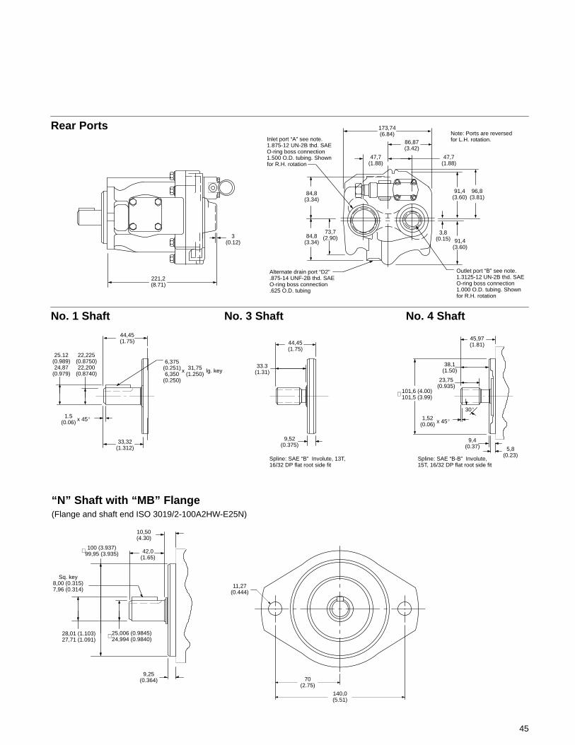
45
Rear Ports
221,2(8.71)
3(0.12)
Inlet port “A” see note.1.875-12 UN-2B thd. SAEO-ring boss connection1.500 O.D. tubing. Shownfor R.H. rotation
Outlet port “B” see note.1.3125-12 UN-2B thd. SAEO-ring boss connection1.000 O.D. tubing. Shownfor R.H. rotation
84,8(3.34)
84,8(3.34)
73,7(2.90) 91,4
(3.60)
3,8(0.15)
91,4(3.60)
96,8(3.81)
173,74(6.84)
86,87(3.42)
47,7(1.88)
47,7(1.88)
Alternate drain port “D2”.875-14 UNF-2B thd. SAEO-ring boss connection.625 O.D. tubing
Note: Ports are reversedfor L.H. rotation.
No. 1 Shaft
44,45(1.75)
No. 3 Shaft
“N” Shaft with “MB” Flange(Flange and shaft end ISO 3019/2-100A2HW-E25N)
33,32(1.312)
25.12(0.989)24,87
(0.979)
22,225(0.8750)22,200
(0.8740)
6,375(0.251)6,350
(0.250)
x 31,75(1.250)
lg. key
44,45(1.75)
Spline: SAE “B” Involute, 13T,16/32 DP flat root side fit
9,52(0.375)
10,50(4.30)
Sq. key8,00 (0.315)7,96 (0.314)
9,25(0.364)
25,006 (0.9845)24,994 (0.9840)
28,01 (1.103)27,71 (1.091)
42,0(1.65)
33.3(1.31)
∅
100 (3.937)99,95 (3.935)∅
140,0(5.51)
70(2.75)
11,27(0.444)
45,97(1.81)
101,6 (4.00)101,5 (3.99)∅
38,1(1.50)
x 45�
23,75(0.935)
30�
9,4(0.37) 5,8
(0.23)
No. 4 Shaft
1,52(0.06)
Spline: SAE “B-B” Involute,15T, 16/32 DP flat root side fit
1.5(0.06) x 45�
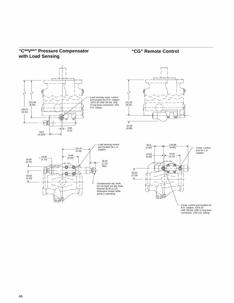
46
“C**V**” Pressure Compensatorwith Load Sensing
“CG” Remote Control
Load sensing comp. controlport location for R.H. rotation.4375-20 UNF-2B thd. SAEO-ring boss connection .250O.D. tubing
239,27(9.42)
215,90(8.50)
63,5(0.250)
6,60(2.6)
Compensator adj. knob.Do not back out adj. knobbeyond 28,45 (1.12)dimension shown whilepump is operating.
Load sensing controlport location for L.H.rotation
28,45(1.12)Max.
131,57(5.18)
74,68(2.94)28,45
(1.12)∅19,05(0.75)
55,63(2.19)
Comp. control port location forR.H. rotation .4375-20UNF-2B thd. SAE O-ring bossconnection .250 O.D. tubing
55,63(2.19)
22,35(0.88)
50,8(2.00)
118,88(4.68) Comp. control
port for L.H.rotation79,25
(3.12)10,92(0.43)
211,32(8.32)
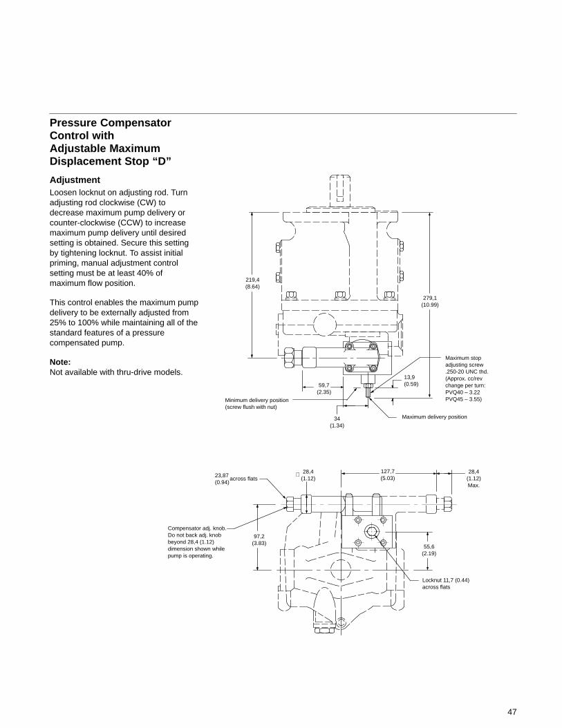
47
Pressure CompensatorControl withAdjustable MaximumDisplacement Stop “D”
AdjustmentLoosen locknut on adjusting rod. Turnadjusting rod clockwise (CW) todecrease maximum pump delivery orcounter-clockwise (CCW) to increasemaximum pump delivery until desiredsetting is obtained. Secure this settingby tightening locknut. To assist initialpriming, manual adjustment controlsetting must be at least 40% ofmaximum flow position.
This control enables the maximum pumpdelivery to be externally adjusted from25% to 100% while maintaining all of thestandard features of a pressurecompensated pump.
Note:Not available with thru-drive models.
219,4(8.64)
279,1(10.99)
13,9(0.59)
34(1.34)
59,7(2.35)
Maximum delivery position
Minimum delivery position(screw flush with nut)
Maximum stopadjusting screw.250-20 UNC thd.(Approx. cc/revchange per turn:PVQ40 – 3.22PVQ45 – 3.55)
23,87(0.94)
across flats28,4
(1.12)∅ 127,7
(5.03)28,4
(1.12)Max.
55,6(2.19)
Locknut 11,7 (0.44)across flats
97,2(3.83)
Compensator adj. knob.Do not back adj. knobbeyond 28,4 (1.12)dimension shown whilepump is operating.
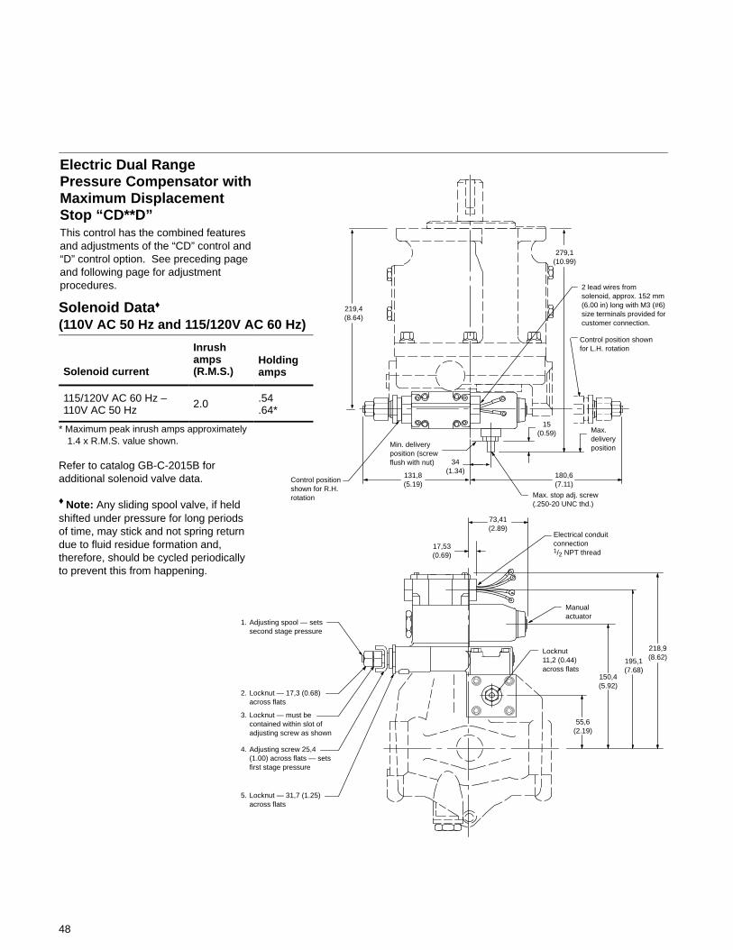
Electric Dual RangePressure Compensator withMaximum DisplacementStop “CD**D”This control has the combined featuresand adjustments of the “CD” control and“D” control option. See preceding pageand following page for adjustmentprocedures.
219,4(8.64)
131,8(5.19)
34(1.34)
180,6(7.11)
Max. stop adj. screw(.250-20 UNC thd.)
73,41(2.89)
17,53(0.69)
Electrical conduitconnection1/2 NPT thread
15(0.59) Max.
deliveryposition
Control position shownfor L.H. rotation
279,1(10.99)
2 lead wires fromsolenoid, approx. 152 mm(6.00 in) long with M3 (#6)size terminals provided forcustomer connection.
Manualactuator
218,9(8.62)195,1
(7.68)150,4(5.92)
Locknut11,2 (0.44)across flats
55,6(2.19)
Min. deliveryposition (screwflush with nut)
Control positionshown for R.H.rotation
1. Adjusting spool — setssecond stage pressure
2. Locknut — 17,3 (0.68)across flats
3. Locknut — must becontained within slot ofadjusting screw as shown
4. Adjusting screw 25,4(1.00) across flats — setsfirst stage pressure
5. Locknut — 31,7 (1.25)across flats
48
Solenoid Data♦
(110V AC 50 Hz and 115/120V AC 60 Hz)
Solenoid current
Inrushamps(R.M.S.)
Holdingamps
115/120V AC 60 Hz –110V AC 50 Hz
2.0 .54.64*
* Maximum peak inrush amps approximately1.4 x R.M.S. value shown.
Refer to catalog GB-C-2015B foradditional solenoid valve data.
♦ Note: Any sliding spool valve, if heldshifted under pressure for long periodsof time, may stick and not spring returndue to fluid residue formation and,therefore, should be cycled periodicallyto prevent this from happening.
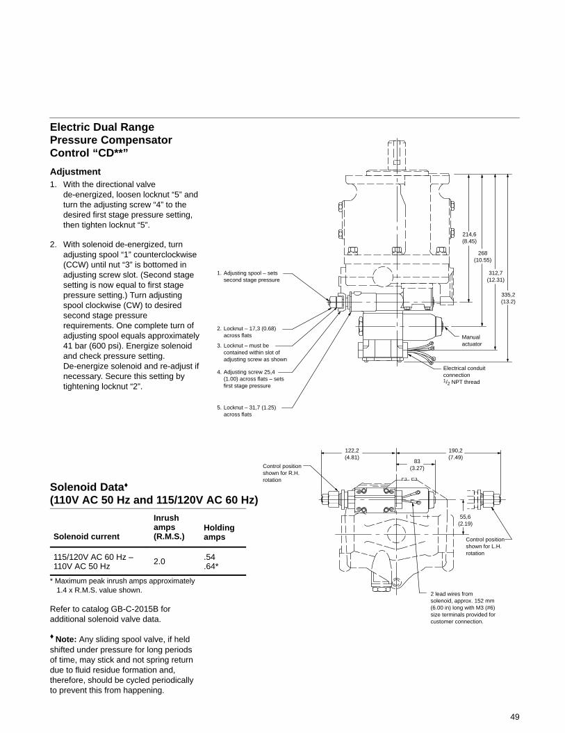
Electric Dual RangePressure CompensatorControl “CD**”
Adjustment1. With the directional valve
de-energized, loosen locknut “5” andturn the adjusting screw “4” to thedesired first stage pressure setting,then tighten locknut “5”.
2. With solenoid de-energized, turnadjusting spool “1” counterclockwise(CCW) until nut “3” is bottomed inadjusting screw slot. (Second stagesetting is now equal to first stagepressure setting.) Turn adjustingspool clockwise (CW) to desiredsecond stage pressurerequirements. One complete turn ofadjusting spool equals approximately41 bar (600 psi). Energize solenoidand check pressure setting.De-energize solenoid and re-adjust ifnecessary. Secure this setting bytightening locknut “2”.
214,6(8.45)
268(10.55)
312,7(12.31)
335,2(13.2)
Manualactuator
Electrical conduitconnection1/2 NPT thread
83(3.27)
190,2(7.49)
122,2(4.81)
Control positionshown for R.H.rotation
Control positionshown for L.H.rotation
2 lead wires fromsolenoid, approx. 152 mm(6.00 in) long with M3 (#6)size terminals provided forcustomer connection.
55,6(2.19)
1. Adjusting spool – setssecond stage pressure
2. Locknut – 17,3 (0.68)across flats
3. Locknut – must becontained within slot ofadjusting screw as shown
4. Adjusting screw 25,4(1.00) across flats – setsfirst stage pressure
5. Locknut – 31,7 (1.25)across flats
49
Solenoid Data♦
(110V AC 50 Hz and 115/120V AC 60 Hz)
Solenoid current
Inrushamps(R.M.S.)
Holdingamps
115/120V AC 60 Hz –110V AC 50 Hz
2.0 .54.64*
* Maximum peak inrush amps approximately1.4 x R.M.S. value shown.
Refer to catalog GB-C-2015B foradditional solenoid valve data.
♦ Note: Any sliding spool valve, if heldshifted under pressure for long periodsof time, may stick and not spring returndue to fluid residue formation and,therefore, should be cycled periodicallyto prevent this from happening.
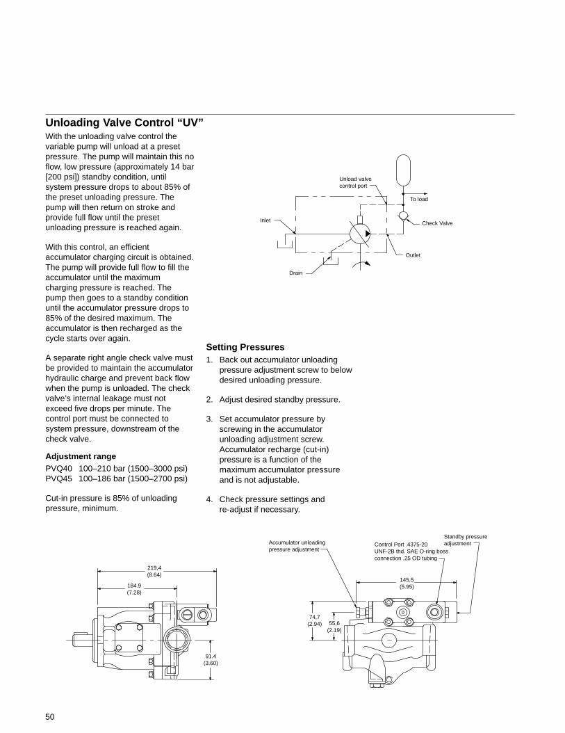
50
With the unloading valve control thevariable pump will unload at a presetpressure. The pump will maintain this noflow, low pressure (approximately 14 bar[200 psi]) standby condition, untilsystem pressure drops to about 85% ofthe preset unloading pressure. Thepump will then return on stroke andprovide full flow until the presetunloading pressure is reached again.
With this control, an efficientaccumulator charging circuit is obtained.The pump will provide full flow to fill theaccumulator until the maximumcharging pressure is reached. Thepump then goes to a standby conditionuntil the accumulator pressure drops to85% of the desired maximum. Theaccumulator is then recharged as thecycle starts over again.
A separate right angle check valve mustbe provided to maintain the accumulatorhydraulic charge and prevent back flowwhen the pump is unloaded. The checkvalve’s internal leakage must notexceed five drops per minute. Thecontrol port must be connected tosystem pressure, downstream of thecheck valve.
Adjustment rangePVQ40 100–210 bar (1500–3000 psi)PVQ45 100–186 bar (1500–2700 psi)
Cut-in pressure is 85% of unloadingpressure, minimum.
Setting Pressures1. Back out accumulator unloading
pressure adjustment screw to belowdesired unloading pressure.
2. Adjust desired standby pressure.
3. Set accumulator pressure byscrewing in the accumulatorunloading adjustment screw.Accumulator recharge (cut-in)pressure is a function of themaximum accumulator pressureand is not adjustable.
4. Check pressure settings andre-adjust if necessary.
Outlet
Drain
Inlet Check Valve
To load
Unload valvecontrol port
184.9(7.28)
91.4(3.60)
145,5(5.95)
219,4(8.64)
55,6(2.19)
74,7(2.94)
Accumulator unloadingpressure adjustment
Control Port .4375-20UNF-2B thd. SAE O-ring bossconnection .25 OD tubing
Standby pressureadjustment
Unloading Valve Control “UV”

51
“A9 & “A11” SAE “A” Thru-Drives
147,57(5.81)
6,35 (0.251)6,30 (0.250) Sq. key
Drain port “D1”. .875-14 UNF-2B thd.SAE O-ring boss connection .825O.D. tubing
87,38(3.44)∅82,55
(3.253)∅
25,4(1.00)
1,42 (0.056)1,32 (0.052)
12,7(0.50)
50,8(2.00)
12,7(0.500)
191,26(7.53)
151,13(5.95)
97,28(3.83)
31,75(1.25)
50.8(2.00)
194,56(7.66)
58,67(2.31)
28,22(1.11)27,97(1.10)
25,37(0.999)25,35(0.998)
∅
No. 2 shaft
28,45(1.12)Max.
34,935(1.375)
Inlet port “A”. See note1.50 diameter inlet. SAEJ518 4-bolt flange.Standard pressure series
.500-13 UNC-2B thd.1.06 deep – 4 places
Do not back out comp.adjusting knob beyondthis dimension whilepump is operating.
84,84(3.34)
45,97(1.81)
101,6 (4.00)101,5 (3.99)∅
38,1(1.50)
1,52 (0.06) x 45�
23,75(0.935)
14,48(0.57)9,4
(0.37)
242,06(9.53)
35,7(1.406)
17,86(0.703)
69,85(2.75)
84,84(3.34)
73,6(2.90)
95,76(3.77)
.375-16 UNC-2Bthd. .72 deep –2 holes
95,25(3.75)∅
Outlet port “B”.See note. 1.00diameter inlet.SAE J518 4-boltflange. Standardpressure series
.375-16 UNC-2B thd.
.88 deep – 4 places
91,44(3.60)
91,95(3.62)
91,95(3.62)
105,43(4.19)
53,09(2.09)
Outlet port “B” face
Alternate drainport “D2”
“A” flange
Load sensing control port.4375-20 UNF-2B thd. SAEO-ring boss connection .250O.D. tubing
22,61(0.89)
Output spline – seethru-drive table on nextpage
Note: Ports are reversedfor L.H. rotation.
13,1(0.516)
26,2(1.031)
26,18(1.031)
52,37(2.062)
A (see table on next page)
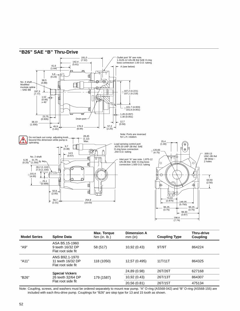
52
“B26” SAE “B” Thru-Drive191,0(7.52)
Do not back out comp. adjusting knobbeyond this dimension while pump isoperating.
142,4(5.61)
Drain port
176,3(6.94)
45,9(1.81)
38,10(1.500)
23,75(0.935)
No. 4 shaftModifiedinvolute spline– SAE BB
197,3(7.77)
98,5(3.88)
5,8(0.23)
41,6(1.64)
1,52(0.06)x 45�
Load sensing control port.4375-20 UNF-2B thd. SAEO-ring boss connection.250 O.D. tubing
254,8(10.03)
56,7(2.31)
50,8(2.00)
101,6(4.00)∅
No. 2 shaft6,35
(0.25) x 31,75(1.250) lg. key
14,5(0.57)
9,7(0.38)
28,45(1.12)Max.
120,65(4.75)∅
Outlet port “B” see note.1.3125-12 UN-2B thd SAE O-ringboss connection 1.00 O.D. tubing
.500-13UNC-2B thd.88 deep –2 holes
63,50(2.50)
73,03(2.875) 146,05
(5.750)
196,6(7.74)
98,30(3.87)
95,25(3.75)
95,25(3.75)
28,2 (1.110)27,9 (1.100)
25,1(0.999)
Note: Ports are reversedfor L.H. rotation.
∅
25,4(1.00)
A (see below)
101,7 (4.003)101,6 (4.001)∅
107,2 (4.221)107,1 (4.219)∅
Inlet port “A” see note. 1.875-12UN-2B thd. SAE O-ring bossconnection 1.500 O.D. tubing
57,2(2.25)
12,7(0.50)
1,45 (0.057)1.30 (0.051)
Model Series Spline DataMax. TorqueNm (in. lb.)
Dimension Amm (in) Coupling Type
Thru-driveCoupling
“A9”ASA B5.15-19609 teeth 16/32 DPFlat root side fit
58 (517) 10,92 (0.43) 9T/9T 864224
“A11”ANS B92.1-197011 teeth 16/32 DPFlat root side fit
118 (1050) 12,57 (0.495) 11T/11T 864325
Special Vickers24,89 (0.98) 26T/26T 627168
“B26”Special Vickers26 teeth 32/64 DPFl t t id fit
179 (1587) 10,92 (0.43) 26T/13T 864307Flat root side fit
( )
20,56 (0.81) 26T/15T 475134
Note: Coupling, screws, and washers must be ordered separately to mount rear pump. “A” O-ring (AS568-042) and “B” O-ring (AS568-155) areincluded with each thru-drive pump. Couplings for “B26” are step type for 13 and 15 tooth as shown.
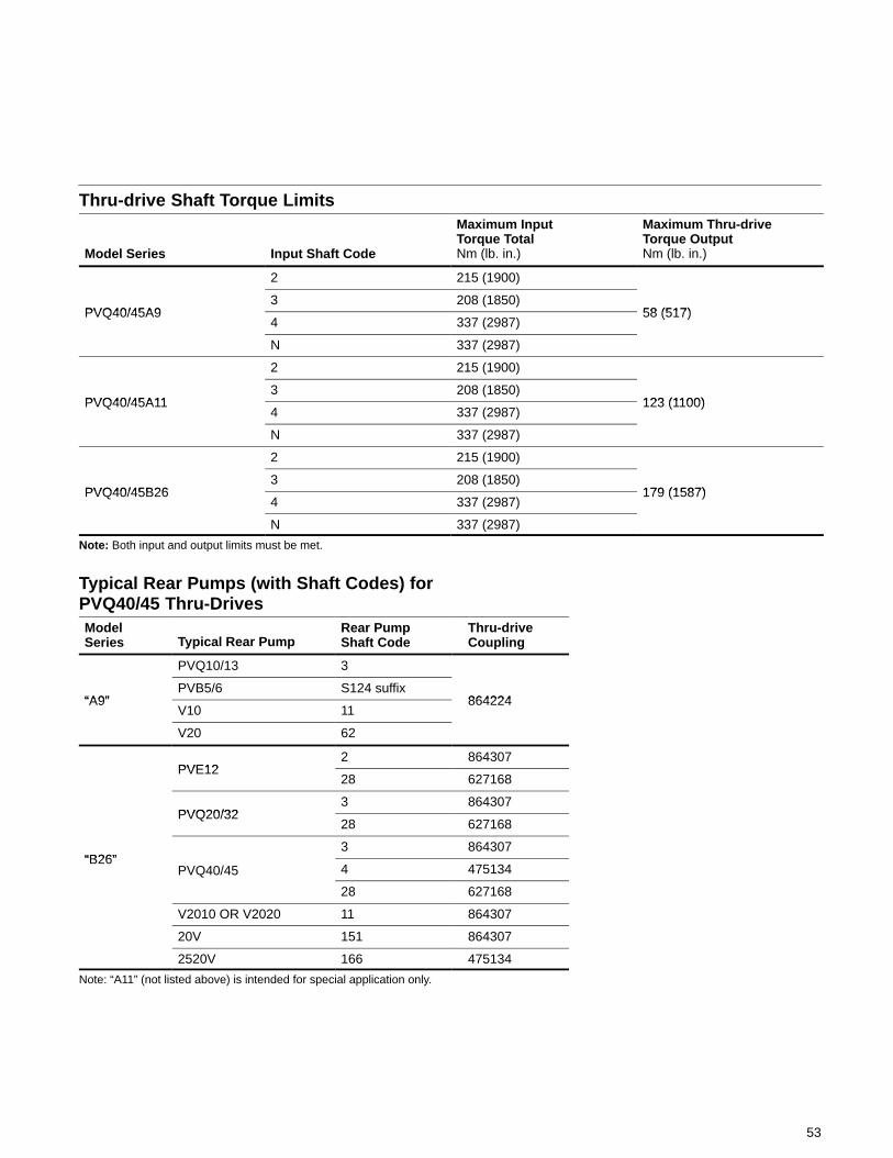
53
Thru-drive Shaft Torque Limits
Model Series Input Shaft Code
Maximum InputTorque TotalNm (lb. in.)
Maximum Thru-driveTorque OutputNm (lb. in.)
2 215 (1900)
PVQ40/45A93 208 (1850)
58 (517)PVQ40/45A94 337 (2987)
58 (517)
N 337 (2987)
2 215 (1900)
PVQ40/45A113 208 (1850)
123 (1100)PVQ40/45A114 337 (2987)
123 (1100)
N 337 (2987)
2 215 (1900)
PVQ40/45B263 208 (1850)
179 (1587)PVQ40/45B264 337 (2987)
179 (1587)
N 337 (2987)
Note: Both input and output limits must be met.
Typical Rear Pumps (with Shaft Codes) for PVQ40/45 Thru-DrivesModelSeries Typical Rear Pump
Rear PumpShaft Code
Thru-driveCoupling
PVQ10/13 3
“A9”PVB5/6 S124 suffix
864224“A9”V10 11
864224
V20 62
PVE122 864307
PVE1228 627168
PVQ20/323 864307
PVQ20/3228 627168
“B26”3 864307
“B26”PVQ40/45 4 475134
28 627168
V2010 OR V2020 11 864307
20V 151 864307
2520V 166 475134
Note: “A11” (not listed above) is intended for special application only.
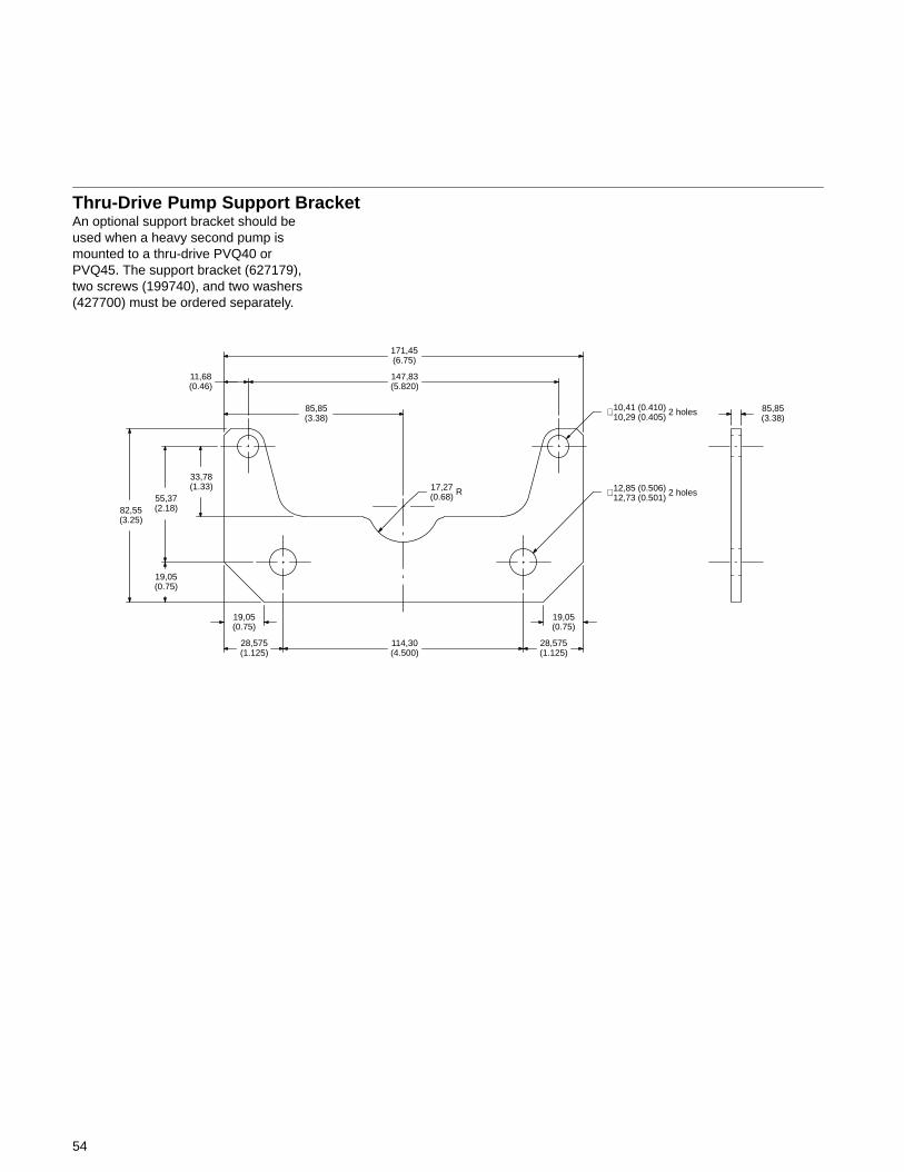
54
Thru-Drive Pump Support BracketAn optional support bracket should beused when a heavy second pump ismounted to a thru-drive PVQ40 orPVQ45. The support bracket (627179),two screws (199740), and two washers(427700) must be ordered separately.
82,55(3.25)
55,37(2.18)
33,78(1.33)
171,45(6.75)
147,83(5.820)
85,85(3.38)
11,68(0.46)
19,05(0.75)
19,05(0.75)
28,575(1.125)
114,30(4.500)
28,575(1.125)
17,27(0.68)
85,85(3.38)
R 12,85 (0.506)12,73 (0.501)
∅ 2 holes
10,41 (0.410)10,29 (0.405)∅ 2 holes
19,05(0.75)
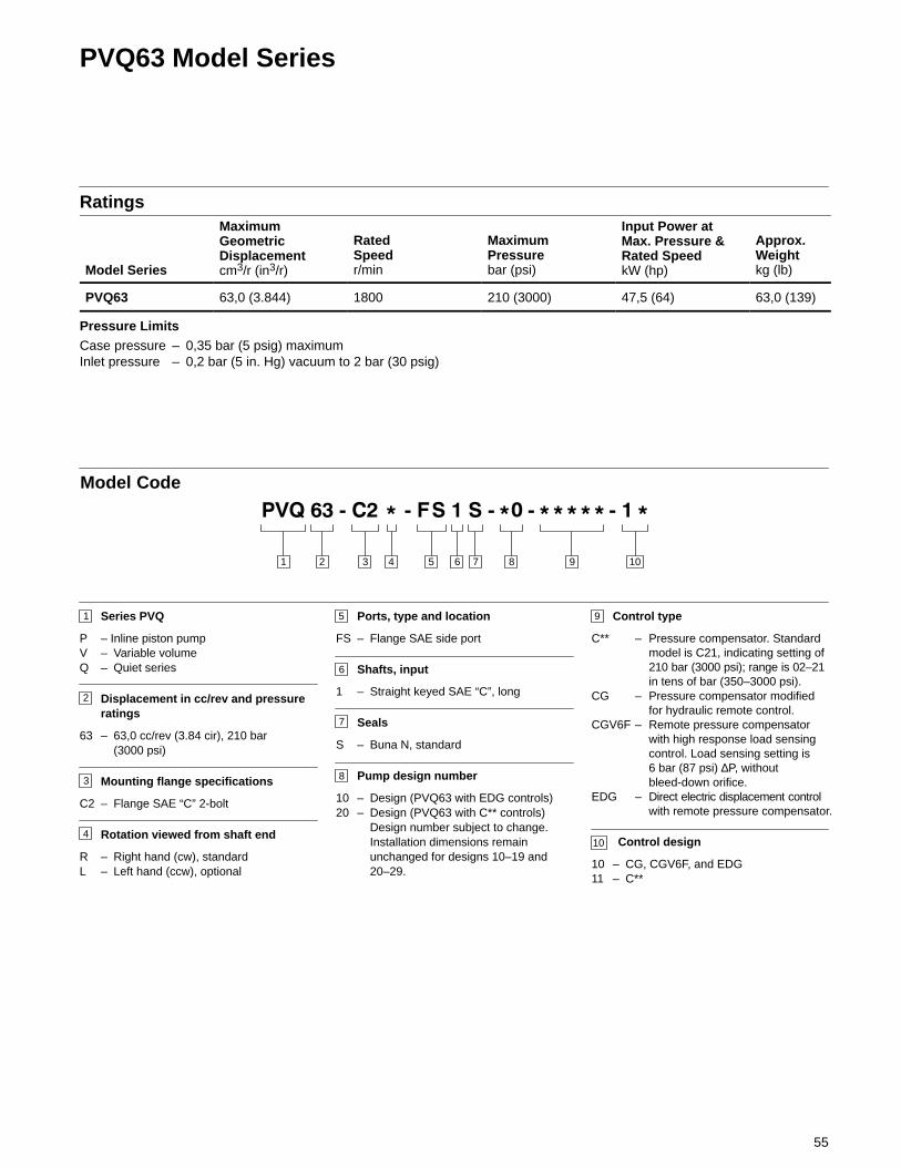
55
PVQ63 Model Series
Ratings
Model Series
MaximumGeometricDisplacementcm3/r (in3/r)
RatedSpeedr/min
MaximumPressurebar (psi)
Input Power atMax. Pressure &Rated SpeedkW (hp)
Approx.Weightkg (lb)
PVQ63 63,0 (3.844) 1800 210 (3000) 47,5 (64) 63,0 (139)
Pressure LimitsCase pressure – 0,35 bar (5 psig) maximumInlet pressure – 0,2 bar (5 in. Hg) vacuum to 2 bar (30 psig)
3 4 5 876 9 101 2
Model Code
1
2
Series PVQ
P – Inline piston pumpV – Variable volumeQ – Quiet series
Displacement in cc/rev and pressureratings
63 – 63,0 cc/rev (3.84 cir), 210 bar(3000 psi)
Mounting flange specifications
C2 – Flange SAE “C” 2-bolt
Rotation viewed from shaft end
R – Right hand (cw), standardL – Left hand (ccw), optional
3
4
5
6
7
8
9
10
Ports, type and location
FS – Flange SAE side port
Shafts, input
1 – Straight keyed SAE “C”, long
Seals
S – Buna N, standard
Pump design number
10 – Design (PVQ63 with EDG controls)20 – Design (PVQ63 with C** controls)
Design number subject to change.Installation dimensions remainunchanged for designs 10–19 and20–29.
Control type
C** – Pressure compensator. Standardmodel is C21, indicating setting of210 bar (3000 psi); range is 02–21in tens of bar (350–3000 psi).
CG – Pressure compensator modifiedfor hydraulic remote control.
CGV6F – Remote pressure compensatorwith high response load sensingcontrol. Load sensing setting is6 bar (87 psi) ∆P, withoutbleed-down orifice.
EDG – Direct electric displacement controlwith remote pressure compensator.
Control design
10 – CG, CGV6F, and EDG11 – C**
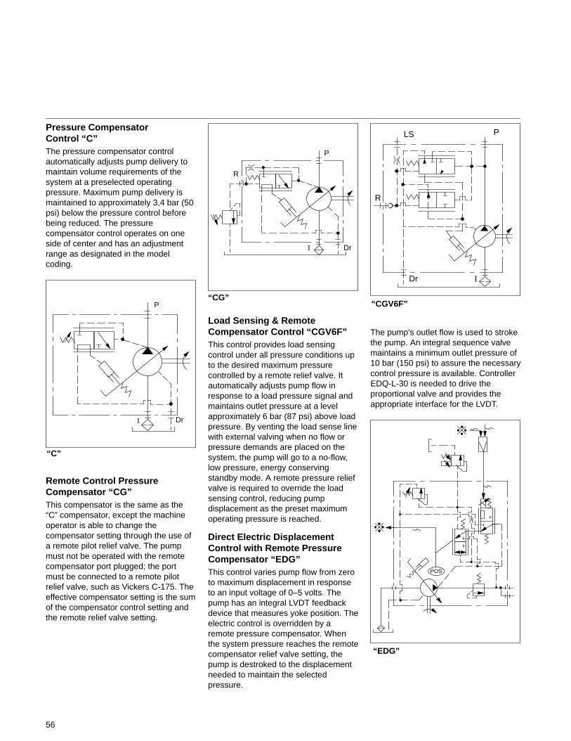
56
Pressure CompensatorControl “C”The pressure compensator controlautomatically adjusts pump delivery tomaintain volume requirements of thesystem at a preselected operatingpressure. Maximum pump delivery ismaintained to approximately 3,4 bar (50psi) below the pressure control beforebeing reduced. The pressurecompensator control operates on oneside of center and has an adjustmentrange as designated in the modelcoding.
“C”
I Dr
P
Remote Control PressureCompensator “CG”This compensator is the same as the“C” compensator, except the machineoperator is able to change thecompensator setting through the use ofa remote pilot relief valve. The pumpmust not be operated with the remotecompensator port plugged; the portmust be connected to a remote pilotrelief valve, such as Vickers C-175. Theeffective compensator setting is the sumof the compensator control setting andthe remote relief valve setting.
“CG”
I Dr
P
R
Load Sensing & RemoteCompensator Control “CGV6F”This control provides load sensingcontrol under all pressure conditions upto the desired maximum pressurecontrolled by a remote relief valve. Itautomatically adjusts pump flow inresponse to a load pressure signal andmaintains outlet pressure at a levelapproximately 6 bar (87 psi) above loadpressure. By venting the load sense linewith external valving when no flow orpressure demands are placed on thesystem, the pump will go to a no-flow,low pressure, energy conservingstandby mode. A remote pressure reliefvalve is required to override the loadsensing control, reducing pumpdisplacement as the preset maximumoperating pressure is reached.
Direct Electric DisplacementControl with Remote PressureCompensator “EDG”This control varies pump flow from zeroto maximum displacement in responseto an input voltage of 0–5 volts. Thepump has an integral LVDT feedbackdevice that measures yoke position. Theelectric control is overridden by aremote pressure compensator. Whenthe system pressure reaches the remotecompensator relief valve setting, thepump is destroked to the displacementneeded to maintain the selectedpressure.
“CGV6F”
IDr
PLS
R
The pump’s outlet flow is used to strokethe pump. An integral sequence valvemaintains a minimum outlet pressure of10 bar (150 psi) to assure the necessarycontrol pressure is available. ControllerEDQ-L-30 is needed to drive theproportional valve and provides theappropriate interface for the LVDT.
“EDG”
POS
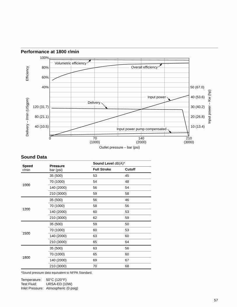
57
Del
iver
y –
l/min
(U
Sgp
m)
Performance at 1800 r/min
0 140(2000)
210(3000)
Outlet pressure – bar (psi)
10 (13.4)
70(1000)
20 (26.8)
30 (40.2)
40 (53.6)
50 (67.0)
40 (10.5)
80 (21.1)
120 (31.7)
40%
60%
80%
100%
Effi
cien
cy
Inpu
t pow
er –
Kw
(hp
)
Volumetric efficiencyOverall efficiency
Input power
Input power pump compensated
Delivery
Sound Data
Speed Press reSound Level dB(A)*
Speedr/min
Pressurebar (psi) Full Stroke Cutoff
35 (500) 53 45
100070 (1000) 54 48
1000140 (2000) 56 54
210 (3000) 59 58
35 (500) 56 46
120070 (1000) 58 56
1200140 (2000) 60 53
210 (3000) 62 59
35 (500) 59 50
150070 (1000) 60 53
1500140 (2000) 63 60
210 (3000) 65 64
35 (500) 63 56
180070 (1000) 65 60
1800140 (2000) 69 67
210 (3000) 70 68
*Sound pressure data equivalent to NFPA Standard.
Temperature: 50°C (120°F)Test Fluid: URSA-ED (10W)Inlet Pressure: Atmospheric (0 psig)
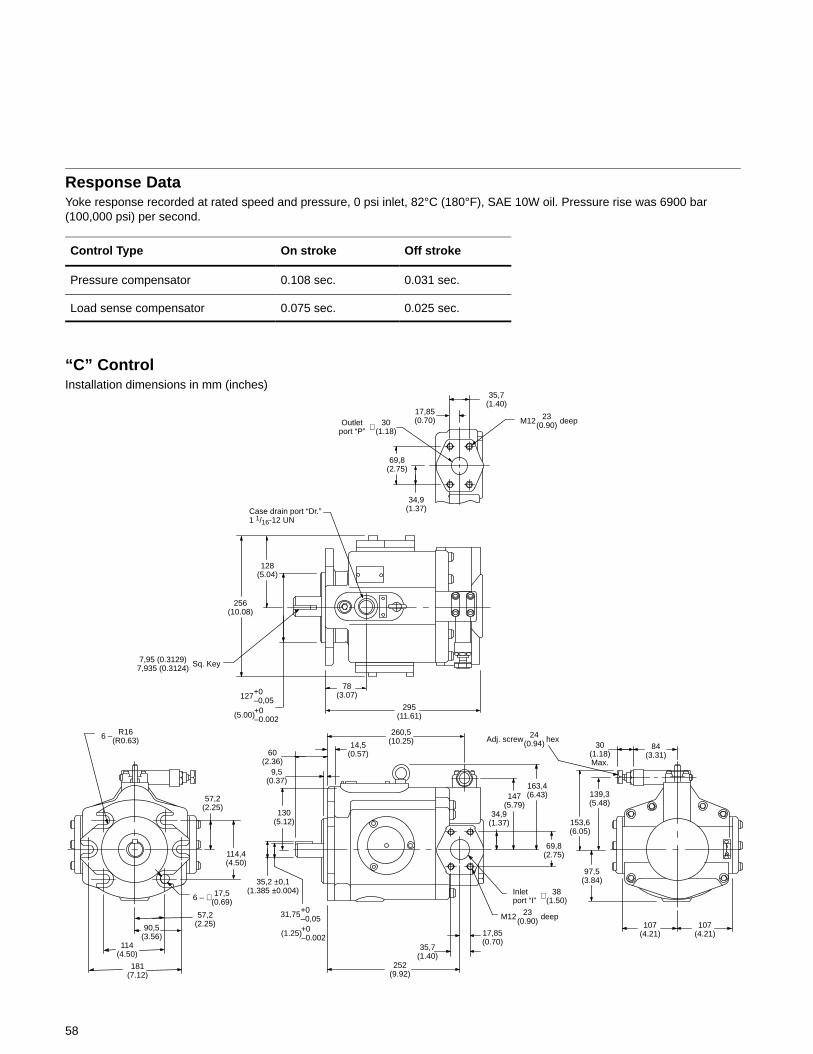
58
Response DataYoke response recorded at rated speed and pressure, 0 psi inlet, 82°C (180°F), SAE 10W oil. Pressure rise was 6900 bar(100,000 psi) per second.
Control Type On stroke Off stroke
Pressure compensator 0.108 sec. 0.031 sec.
Load sense compensator 0.075 sec. 0.025 sec.
“C” ControlInstallation dimensions in mm (inches)
35,7(1.40)
17,85(0.70)30
(1.18)∅
69,8(2.75)
34,9(1.37)
128(5.04)
256(10.08)
78(3.07)
295(11.61)
Case drain port “Dr.”1 1/16-12 UN
260,5(10.25)14,5
(0.57)60(2.36)
9,5(0.37)
130(5.12)
35,2 ±0,1(1.385 ±0.004)
252(9.92)
35,7(1.40)
17,85(0.70)
M12
69,8(2.75)
163,4(6.43)
34,9(1.37)
147(5.79)
84(3.31)
30(1.18)Max.
Adj. screw
107(4.21)
107(4.21)
97,5(3.84)
153,6(6.05)
139,3(5.48)57,2
(2.25)
114,4(4.50)
181(7.12)
114(4.50)
90,5(3.56)
57,2(2.25)
17,5(0.69)
R16(R0.63)
7,95 (0.3129)7,935 (0.3124) Sq. Key
Outletport “P”
+0–0,05127
(5.00)+0–0.002
6 –
6 – ∅+0–0,0531,75
(1.25)+0–0.002
23(0.90) deep
hex24(0.94)
38(1.50)
Inletport “I”
∅
M12 23(0.90) deep
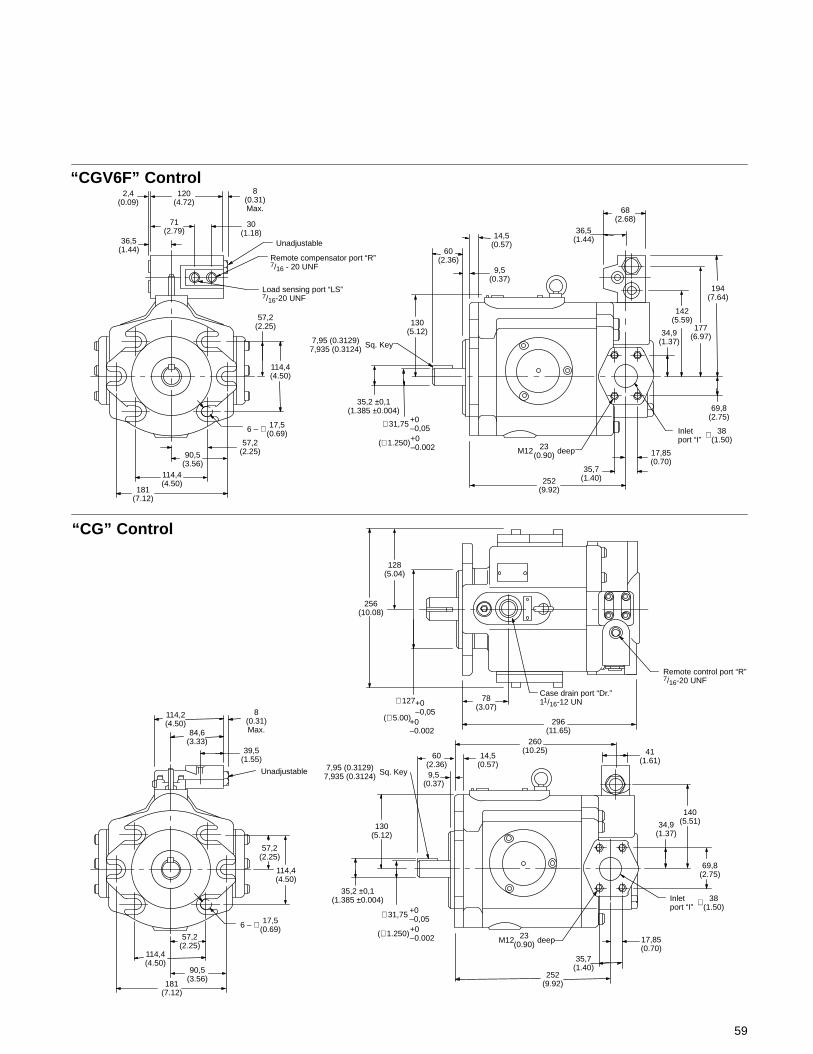
59
“CG” Control
128(5.04)
256(10.08)
78(3.07)
296(11.65)
Remote control port “R”7/16-20 UNF
Case drain port “Dr.”11/16-12 UN
130(5.12)
60(2.36)9,5
(0.37)
14,5(0.57)
260(10.25) 41
(1.61)
140(5.51)34,9
(1.37)
69,8(2.75)
17,85(0.70)
35,7(1.40)
252(9.92)
114,4(4.50)
57,2(2.25)
181(7.12)
90,5(3.56)
114,4(4.50)
57,2(2.25)
Unadjustable
114,2(4.50)
84,6(3.33)
39,5(1.55)
8(0.31)Max.
120(4.72)
2,4(0.09)
8(0.31)Max.
30(1.18)
Unadjustable
Remote compensator port “R”7/16 - 20 UNF
Load sensing port “LS”7/16-20 UNF
57,2(2.25)
114,4(4.50)
17,5(0.69)
57,2(2.25)
181(7.12)
60(2.36)
9,5(0.37)
14,5(0.57)
36,5(1.44)
34,9(1.37)
142(5.59)
194(7.64)
69,8(2.75)
17,85(0.70)
35,7(1.40)252
(9.92)
130(5.12)
114,4(4.50)
90,5(3.56)
177(6.97)
68(2.68)71
(2.79)36,5
(1.44)
“CGV6F” Control
6 – ∅
35,2 ±0,1(1.385 ±0.004)
7,95 (0.3129)7,935 (0.3124) Sq. Key
+0–0,05∅ 31,75
(∅ 1.250)+0–0.002 M12 23
(0.90) deep
38(1.50)
Inletport “I”
∅
+0–0,05
∅ 127
(∅ 5.00)+0–0.002
17,5(0.69)6 – ∅
35,2 ±0,1(1.385 ±0.004)
7,95 (0.3129)7,935 (0.3124) Sq. Key
+0–0,05∅ 31,75
(∅ 1.250)+0–0.002 M12 23
(0.90) deep
38(1.50)
Inletport “I”
∅
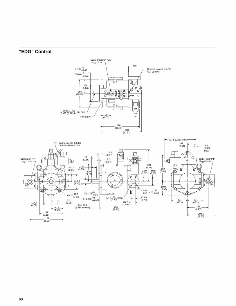
60
“EDG” Control
Remote control port “R”7/16-20 UNF
256(10.08)
128(5.04)
Filling port78
(3.07)
296(11.65)
318(12.52)
Case drain port “Dr.”11/16-12UN
Outlet port “P”11/16-12UN
Connector JIS C 5432CNR01SPF 013 005
114,4(4.50)
158(6.22)
181(7.12)
90,5(3.56)
57,2(2.25)
252(9.92)
35,7(1.40)
17,85(0.70)
34,9(1.37)
241(9.49)
69,8(2.75)
100,5(3.96)
194(7.64)
237,5 (9.35) Max.
67(2.64) 8,5
(0.33)Max.
Outlet port “P1”11/16-12UN
107(4.21)
107(4.21)
158(6.22)
209,5(8.25)
130(5.12)
31,8(1.25)
14,5(0.57)
9,5(0.37)
60(2.36)
114,4(4.50)
57,2(2.25)
+0–0,05∅ 127
(∅ 5.00)+0–0.002
35,2 ±0,1(1.385 ±0.004)
7,95 (0.3129)7,935 (0.3124) Sq. Key
+0–0,05∅ 31,75
(∅ 1.250)+0–0.002
17,5(0.69)6 – ∅
M12 23(0.90) deep
38(1.50)
Inletport “I”
∅
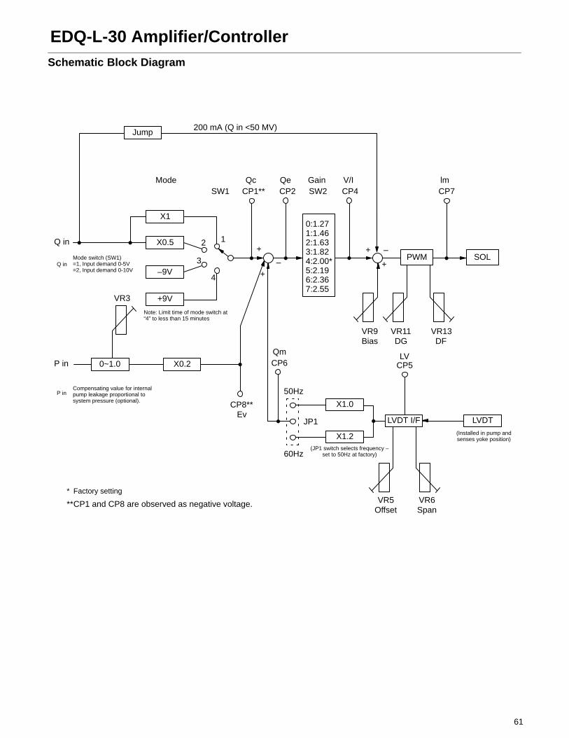
61
EDQ-L-30 Amplifier/ControllerSchematic Block Diagram
Jump200 mA (Q in <50 MV)
Q in
X1
X0.5
–9V
+9V
X0.20~1.0
Mode
12
3
4
+
+–
+
+
–PWM SOL
P in
X1.0
X1.2
LVDT I/F LVDT
0:1.271:1.462:1.633:1.824:2.00*5:2.196:2.367:2.55
* Factory setting
**CP1 and CP8 are observed as negative voltage.
SW1 CP1** CP2 SW2 CP4 CP7
CP8**
Qc Qe Gain V/I lm
VR9 VR11 VR13Bias DG DF
LVCP5
50Hz
60Hz
Ev
VR3
JP1(Installed in pump andsenses yoke position)
(JP1 switch selects frequency –set to 50Hz at factory)
Q inMode switch (SW1)=1, Input demand 0-5V=2, Input demand 0-10V
P inCompensating value for internalpump leakage proportional tosystem pressure (optional).
Note: Limit time of mode switch at“4” to less than 15 minutes
VR5 VR6Offset Span
CP6Qm
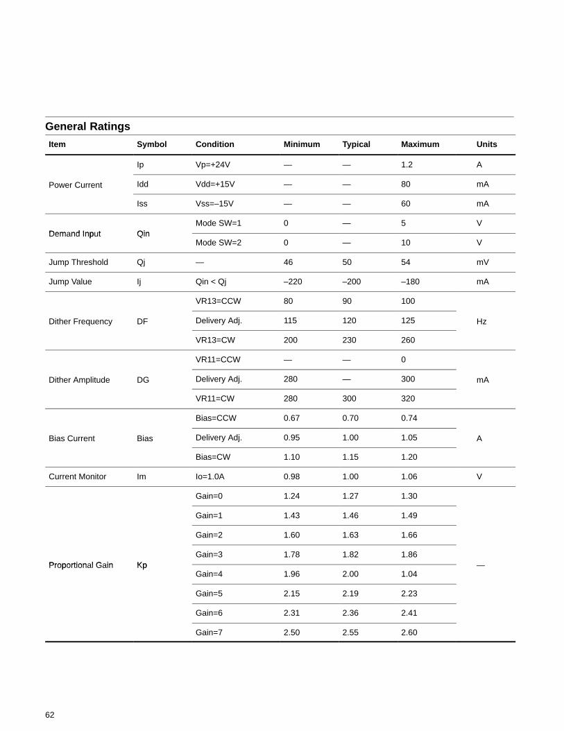
62
General Ratings
Item Symbol Condition Minimum Typical Maximum Units
Ip Vp=+24V — — 1.2 A
Power Current Idd Vdd=+15V — — 80 mA
Iss Vss=–15V — — 60 mA
Dem nd Inp t QinMode SW=1 0 — 5 V
Demand Input QinMode SW=2 0 — 10 V
Jump Threshold Qj — 46 50 54 mV
Jump Value Ij Qin < Qj –220 –200 –180 mA
VR13=CCW 80 90 100
Dither Frequency DF Delivery Adj. 115 120 125 Hz
VR13=CW 200 230 260
VR11=CCW — — 0
Dither Amplitude DG Delivery Adj. 280 — 300 mA
VR11=CW 280 300 320
Bias=CCW 0.67 0.70 0.74
Bias Current Bias Delivery Adj. 0.95 1.00 1.05 A
Bias=CW 1.10 1.15 1.20
Current Monitor Im Io=1.0A 0.98 1.00 1.06 V
Gain=0 1.24 1.27 1.30
Gain=1 1.43 1.46 1.49
Gain=2 1.60 1.63 1.66
Proportion l G in KpGain=3 1.78 1.82 1.86
Proportional Gain KpGain=4 1.96 2.00 1.04
—
Gain=5 2.15 2.19 2.23
Gain=6 2.31 2.36 2.41
Gain=7 2.50 2.55 2.60
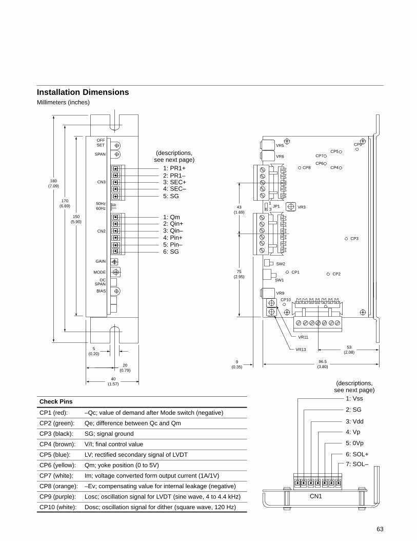
Installation DimensionsMillimeters (inches)
OFFSET
SPAN
CN3
CN2
OCSPAN
BIAS
43(1.69)
75(2.95)
9(0.35)
96.5(3.80)
53(2.08)
40(1.57)
5(0.20)
20(0.79)
CP8
CP5CP7
CP3
150(5.90)
170(6.69)
180(7.09)
VR5
VR6
CP6CP4
CP9
1
3JP1 VR3
CP2CP1
CP10
VR11
VR13
VR9
SW1
SW2
MODE
GAIN
50Hz60Hz
1: PR1+2: PR1–3: SEC+4: SEC–5: SG
1: Qm2: Qin+3: Qin–4: Pin+5: Pin–6: SG
(descriptions,see next page)
1: Vss
2: SG
3: Vdd
4: Vp
5: 0Vp
6: SOL+
7: SOL–
(descriptions,see next page)
CN1
63
Check Pins
CP1 (red): –Qc; value of demand after Mode switch (negative)
CP2 (green): Qe; difference between Qc and Qm
CP3 (black): SG; signal ground
CP4 (brown): V/I; final control value
CP5 (blue): LV; rectified secondary signal of LVDT
CP6 (yellow): Qm; yoke position (0 to 5V)
CP7 (white): Im; voltage converted form output current (1A/1V)
CP8 (orange): –Ev; compensating value for internal leakage (negative)
CP9 (purple): Losc; oscillation signal for LVDT (sine wave, 4 to 4.4 kHz)
CP10 (white): Dosc; oscillation signal for dither (square wave, 120 Hz)
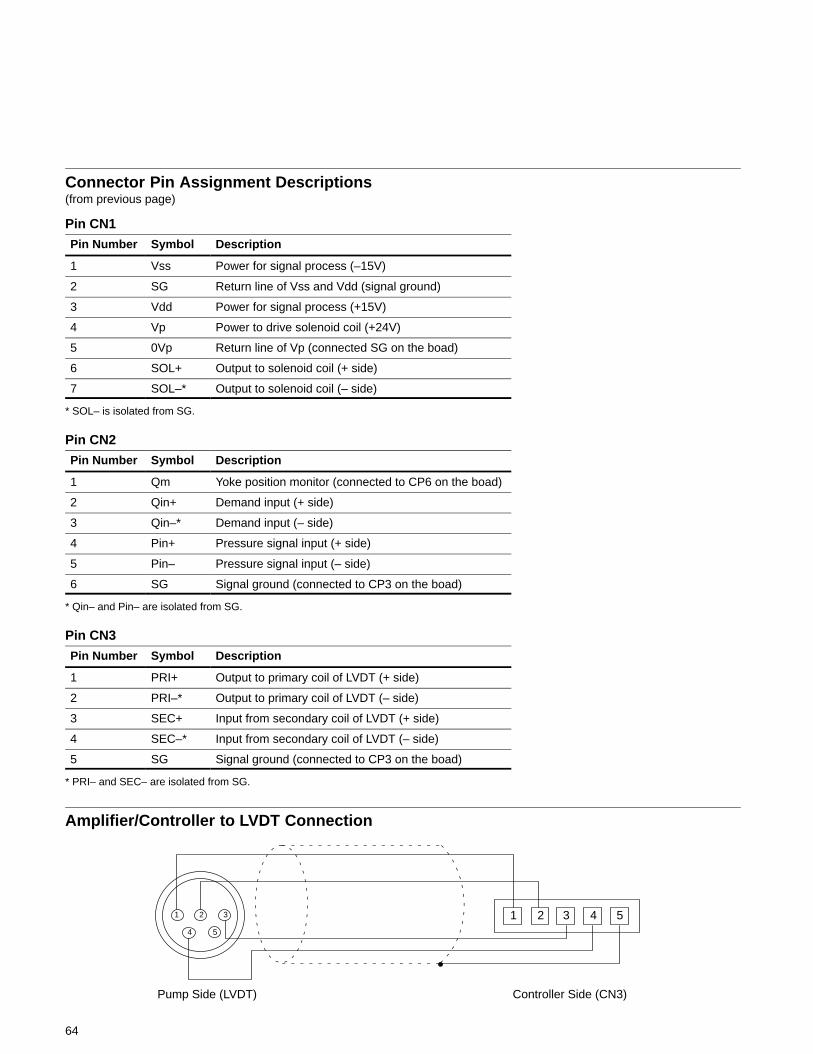
64
Connector Pin Assignment Descriptions(from previous page)
Pin CN1
Pin Number Symbol Description
1 Vss Power for signal process (–15V)
2 SG Return line of Vss and Vdd (signal ground)
3 Vdd Power for signal process (+15V)
4 Vp Power to drive solenoid coil (+24V)
5 0Vp Return line of Vp (connected SG on the boad)
6 SOL+ Output to solenoid coil (+ side)
7 SOL–* Output to solenoid coil (– side)
* SOL– is isolated from SG.
Pin CN2
Pin Number Symbol Description
1 Qm Yoke position monitor (connected to CP6 on the boad)
2 Qin+ Demand input (+ side)
3 Qin–* Demand input (– side)
4 Pin+ Pressure signal input (+ side)
5 Pin– Pressure signal input (– side)
6 SG Signal ground (connected to CP3 on the boad)
* Qin– and Pin– are isolated from SG.
Pin CN3
Pin Number Symbol Description
1 PRI+ Output to primary coil of LVDT (+ side)
2 PRI–* Output to primary coil of LVDT (– side)
3 SEC+ Input from secondary coil of LVDT (+ side)
4 SEC–* Input from secondary coil of LVDT (– side)
5 SG Signal ground (connected to CP3 on the boad)
* PRI– and SEC– are isolated from SG.
Amplifier/Controller to LVDT Connection
1 2 3 4 51 2 3
4 5
Pump Side (LVDT) Controller Side (CN3)
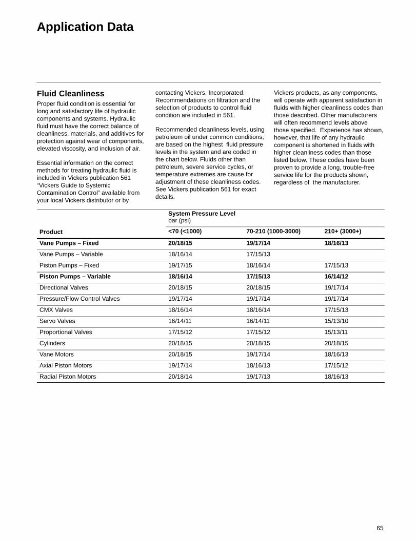
65
Application Data
Fluid CleanlinessProper fluid condition is essential forlong and satisfactory life of hydrauliccomponents and systems. Hydraulicfluid must have the correct balance ofcleanliness, materials, and additives forprotection against wear of components,elevated viscosity, and inclusion of air.
Essential information on the correctmethods for treating hydraulic fluid isincluded in Vickers publication 561“Vickers Guide to SystemicContamination Control” available fromyour local Vickers distributor or by
contacting Vickers, Incorporated.Recommendations on filtration and theselection of products to control fluidcondition are included in 561.
Recommended cleanliness levels, usingpetroleum oil under common conditions,are based on the highest fluid pressurelevels in the system and are coded inthe chart below. Fluids other thanpetroleum, severe service cycles, ortemperature extremes are cause foradjustment of these cleanliness codes.See Vickers publication 561 for exactdetails.
Vickers products, as any components,will operate with apparent satisfaction influids with higher cleanliness codes thanthose described. Other manufacturerswill often recommend levels abovethose specified. Experience has shown,however, that life of any hydrauliccomponent is shortened in fluids withhigher cleanliness codes than thoselisted below. These codes have beenproven to provide a long, trouble-freeservice life for the products shown,regardless of the manufacturer.
System Pressure Levelbar (psi)
Product <70 (<1000) 70-210 (1000-3000) 210+ (3000+)
Vane Pumps – Fixed 20/18/15 19/17/14 18/16/13
Vane Pumps – Variable 18/16/14 17/15/13
Piston Pumps – Fixed 19/17/15 18/16/14 17/15/13
Piston Pumps – Variable 18/16/14 17/15/13 16/14/12
Directional Valves 20/18/15 20/18/15 19/17/14
Pressure/Flow Control Valves 19/17/14 19/17/14 19/17/14
CMX Valves 18/16/14 18/16/14 17/15/13
Servo Valves 16/14/11 16/14/11 15/13/10
Proportional Valves 17/15/12 17/15/12 15/13/11
Cylinders 20/18/15 20/18/15 20/18/15
Vane Motors 20/18/15 19/17/14 18/16/13
Axial Piston Motors 19/17/14 18/16/13 17/15/12
Radial Piston Motors 20/18/14 19/17/13 18/16/13

ÉÉÉÉÉÉÉÉÉÉÉÉÉÉÉÉÉÉÉÉÉÉÉÉÉÉÉÉÉÉÉÉÉÉÉÉÉÉÉÉÉÉÉÉÉÉÉÉÉÉÉÉÉÉÉÉÉÉÉÉÉÉÉÉÉÉÉÉÉÉÉÉÉÉÉÉÉÉÉÉÉÉÉÉ
SUS2300
cSt500
250
70 13
54
–20 10 38 65 82 �C
�F–4 50 100 150 180
Extreme performance envelope
Temperature
Viscosity
Typical SAE 10Wviscosity grade oil
Optimum performanceenvelope
Hydraulic Fluids andTemperature RangesUse antiwear hydraulic oil, orautomotive type crankcase oildesignations SC, SD, SE or SF per SAEJ183FEB80.
Select a viscosity grade that will allowoptimum viscosity, between 40 cSt (180SUS) and 16 cSt (80 SUS), to beachieved within the optimumperformance envelope shown below.
For further information, see Vickers datasheet B-920 or I-286-S.
Fire Resistant FluidsAll pumps can be used with water glycoland polyol ester fluids. All except
PVQ16 and PVQ63 can be used withphosphate ester fluids. All pumps canbe operated to 140 bar (2000 psi) withthese fluids, except PVQ13 and PVQ32which are limited to 105 bar (1500 psi).Input speed should not exceed 1800r/min. System temperature should notexceed 54° C (130° F). Inlet vacuumshould not exceed 101,6 millibar (3 in.Hg). For more information, refer toVickers publication 579.
Installation and Start-up(Commissioning)Before a pump is started, fill the casethrough the uppermost drain port withhydraulic oil of the type to be used. Thecase drain line must be connected to thereservoir below oil level.
For multiple pump arrangements thatinclude non-PVQ sections, therequirements of the non-PVQ units mustbe considered.
Ordering ProcedureOrder pumps by the full modeldesignation. Pump displacement,mounting flange type, direction ofrotation, pump configuration, shaft endtype, seals, pressure adjustment range,and specific control functions are allspecified in the full model code.
Couplings, O-rings, capscrews andwashers must be ordered separately forall thru-drive pumps.