PVLP-SLP Power Vent Low Profile - Hearth N...
34
1 Hearth & Home Technologies • Power Vent Low Profile (PVLP-SLP) Instructions • 4052-900 Rev. Q • 4/18 PVLP-SLP Power Vent Low Profile - Installation Instructions - INTRODUCTION The Power Vent Low Profile (PVLP-SLP) is certified for use as a horizontal termination cap only on fireplaces manufactured by Hearth & Home Technologies with IPI (in- termittent pilot ignition) gas controls. Fireplaces equipped with millivolt type gas controls CANNOT use this product. 1 Introduction DO NOT DISCARD THIS MANUAL NOTICE • Leave this manual with party responsible for use and operation. DO NOT DISCARD • Important operating and maintenance instructions included. • Read, understand and follow these instructions for safe installation and operation. Table of Contents 1 Introduction A. Components and Service Parts List .................. 2 B. Installation of PVLP-SLP .......................... 3 2 Vent Information and Diagrams A. Installation of Vent Pipe ........................... 4 B. Vent/Pipe Regulations ............................ 4 C. Venting Length - Model Categories and Length Requirements by Termination Type ................. 9 3 Framing and Clearances A. Framing and Clearances .......................... 10 B. Termination Cap Clearances ....................... 12 C. Installing Vent Cap .............................. 13 4 Electrical Information A. Wiring the Appliance for the PVLP-SLP with IntelliFire™ Plus Controls ...................................... 18 B. Wiring the Appliance for the PVLP-SLP with IntelliFire™ Touch (IFT) Controls .................................. 23 C. Pairing the IFT-RC400 to the Electronic Control Electronic Control module (IFT-ECM) ........................ 27 IMPORTANT: Failure to read and follow these instruc- tions may create a possible hazard and will void the fire- place warranty. These instructions must remain with the equipment. CAUTION! Risk of Cuts or Abrasions. Wear protective gloves and safety glasses during installation. Sheet metal edges are sharp. Installation of the PVLP-SLP may be done by a quali- fied service technician only. Installation MUST com- ply with local, regional, state and national codes and regulations. 5 Operating Instructions A. Installation Inspection ............................ 28 B. Setting the PVLP-SLP Baffle Adjustment ............. 28 C. Power Vent Operating Instructions .................. 28 D. Maintenance ................................... 29 E. Replace Blower/Pressure Switch ................... 29 F. PVLP-SLP Troubleshooting ........................ 31 G. IFT-Controls and PVI-SLP Power Vent Troubleshooting . .32 H. Addendum: Signature Command Fireplaces. . . . . . . . . . . 33
Transcript of PVLP-SLP Power Vent Low Profile - Hearth N...

1 Hearth & Home Technologies • Power Vent Low Profile (PVLP-SLP) Instructions • 4052-900 Rev. Q • 4/18
PVLP-SLPPower Vent Low Profile
- Installation Instructions -
INTRODUCTIONThe Power Vent Low Profile (PVLP-SLP) is certified for use as a horizontal termination cap only on fireplaces manufactured by Hearth & Home Technologies with IPI (in-termittent pilot ignition) gas controls. Fireplaces equipped with millivolt type gas controls CANNOT use this product.
1 Introduction
DO NOT DISCARD THIS MANUAL
NOTICE
• Leave this manual with party responsible for use and operation.
DO NOTDISCARD
• Important operating and maintenance instructions included.
• Read, understand and follow these instructions for safe installation and operation.
Table of Contents1 Introduction A. Components and Service Parts List . . . . . . . . . . . . . . . . . . 2B. Installation of PVLP-SLP . . . . . . . . . . . . . . . . . . . . . . . . . . 3
2 Vent Information and Diagrams A. Installation of Vent Pipe . . . . . . . . . . . . . . . . . . . . . . . . . . . 4B. Vent/Pipe Regulations . . . . . . . . . . . . . . . . . . . . . . . . . . . . 4C. Venting Length - Model Categories and Length Requirements by Termination Type . . . . . . . . . . . . . . . . . 9
3 Framing and Clearances A. Framing and Clearances . . . . . . . . . . . . . . . . . . . . . . . . . . 10B. Termination Cap Clearances . . . . . . . . . . . . . . . . . . . . . . . 12C. Installing Vent Cap . . . . . . . . . . . . . . . . . . . . . . . . . . . . . . 13
4 Electrical Information A. Wiring the Appliance for the PVLP-SLP with IntelliFire™ Plus
Controls . . . . . . . . . . . . . . . . . . . . . . . . . . . . . . . . . . . . . . 18B. Wiring the Appliance for the PVLP-SLP with IntelliFire™ Touch
(IFT) Controls . . . . . . . . . . . . . . . . . . . . . . . . . . . . . . . . . . 23C. Pairing the IFT-RC400 to the Electronic Control Electronic
Control module (IFT-ECM) . . . . . . . . . . . . . . . . . . . . . . . . 27
IMPORTANT: Failure to read and follow these instruc-tions may create a possible hazard and will void the fire-place warranty.These instructions must remain with the equipment.CAUTION! Risk of Cuts or Abrasions. Wear protective gloves and safety glasses during installation. Sheet metal edges are sharp.
Installation of the PVLP-SLP may be done by a quali-fied service technician only. Installation MUST com-ply with local, regional, state and national codes and regulations.
5 Operating Instructions A. Installation Inspection . . . . . . . . . . . . . . . . . . . . . . . . . . . . 28B. Setting the PVLP-SLP Baffle Adjustment . . . . . . . . . . . . . 28C. Power Vent Operating Instructions . . . . . . . . . . . . . . . . . . 28D. Maintenance . . . . . . . . . . . . . . . . . . . . . . . . . . . . . . . . . . . 29E. Replace Blower/Pressure Switch . . . . . . . . . . . . . . . . . . . 29F. PVLP-SLP Troubleshooting . . . . . . . . . . . . . . . . . . . . . . . . 31G. IFT-Controls and PVI-SLP Power Vent Troubleshooting . .32H. Addendum: Signature Command Fireplaces. . . . . . . . . . . 33

2 Hearth & Home Technologies • Power Vent Low Profile (PVLP-SLP) Instructions • 4052-900 Rev. Q • 4/18
BLOWER ASSEMBLY4052-796
VACUUM SWITCH4052-840
NOTE: Wire Harness connecting PVI to appliance sold separately. The length of wire harness needed varies by installation.For all appliances other than the premium linear models a PVLP-CK conversion kit is required. This kit includes all components to install the PVLP-SLP.
Figure 1.1 Service Parts
A. Components and Service Parts ListService Parts ListReplacement parts can be obtained from your dealer. Re-pair of the Power Vent should only be done by a qualified service technician.
Required Wire HarnessLengths Available Part Number
10 ft. PV Wire Harness PVI-WH1020 ft. PV Wire Harness PVI-WH2040 ft. PV Wire Harness PVI-WH4060 ft. PV Wire Harness PVI-WH6080 ft. PV Wire Harness PVI-WH80100 ft. PV Wire Harness PVI-WH100
NOTICE: The blower motors present in this power vent will generate sound during operation. The effects of the increased sound level can be minimized with careful plan-ning during installation of the system.
IMPORTANT OPERATIONAL NOTE: When the control being used to run the fireplace is activated, a 120 seconds delay will occur before pilot ignition will begin. This is to allow a pre-purge by the PVLP-SLP. If, after 135 seconds, the pilot and burner do not light, refer to the Troubleshooting section of this instruction for further direction. There will also be a 20-minute post-purge in which the PVLP-SLP will continue to run after appliance is turned off.
NOTE: Wire Harness connecting PVLP-SLP to appliance sold separately. The length of wire harness needed varies by installation. For all appliances equipped with IntelliFire™ or IntelliFire™ Plus ignition, other than the PRIMO, PV-IPI-CK con-version kit and one of the following; RC100, RC200 or RC300 are required. This kit includes all components to install the PVLP-SLP to IntelliFire™ or IntelliFire™ Plus appliances. For appliances equipped with IntelliFire™ Touch (IFT) controls, an IFT-RC400 remote and an IFT-ACM are required on the appliance.
NOTE: The battery back-up and wired wall switch fea-ture of any IPI system are removed when the PVLP-SLP power vent is installed. The fireplace may no longer be operated with battery back-up and/or a wired wall switch.
The PVLP-SLP operates on 120VAC, 60Hz electrical service which is supplied at the fireplace junction box.
NOTE: PVLP-SLP requires special control system configurations:
• For IntelliFire™ and IntelliFire™ Plus models, a RC100, RC200 or RC300 and PV-IPI-CK control system is required for installation (except on PRIMO models). The PV-IPI-CK is sold separately.
• For IntelliFire™ Touch models, an IFT-ACM and IFT-RC400 is required for installation. The IFT-ACM and IFT-RC400 may need to be purchased separately if the appliance is not already equipped with IFT.
• The battery-backup feature cannot be used with models configured with the PVLP-SLP.
• The wired wall switch feature cannot be used with models configured with the PVLP-SLP.
• An appliance with PVLP-SLP installed cannot be operated with battery-backup or a wired wall switch.
3 Hearth & Home Technologies • Power Vent Low Profile (PVLP-SLP) Instructions • 4052-900 Rev. Q • 4/18
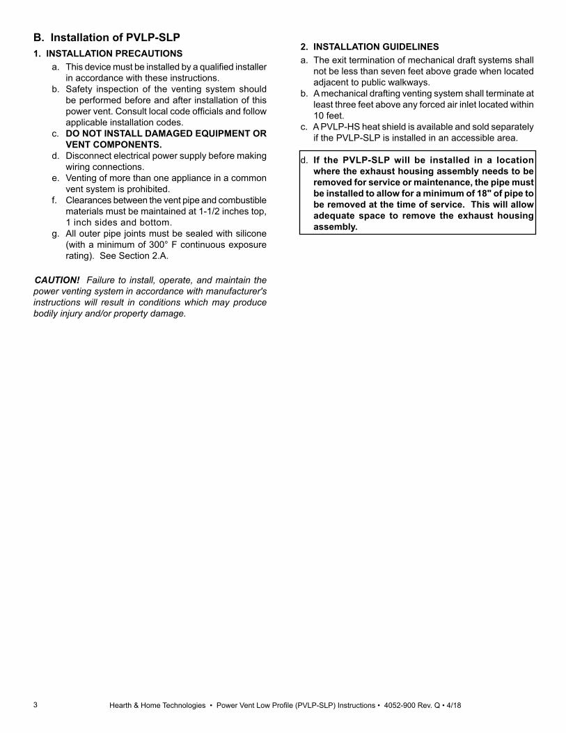
B. Installation of PVLP-SLP1. INSTALLATION PRECAUTIONS
a. This device must be installed by a qualified installer in accordance with these instructions.
b. Safety inspection of the venting system should be performed before and after installation of this power vent. Consult local code officials and follow applicable installation codes.
c. DO NOT INSTALL DAMAGED EQUIPMENT OR VENT COMPONENTS.
d. Disconnect electrical power supply before making wiring connections.
e. Venting of more than one appliance in a common vent system is prohibited.
f. Clearances between the vent pipe and combustible materials must be maintained at 1-1/2 inches top, 1 inch sides and bottom.
g. All outer pipe joints must be sealed with silicone (with a minimum of 300° F continuous exposure rating). See Section 2.A.
CAUTION! Failure to install, operate, and maintain the power venting system in accordance with manufacturer's instructions will result in conditions which may produce bodily injury and/or property damage.
2. INSTALLATION GUIDELINESa. The exit termination of mechanical draft systems shall
not be less than seven feet above grade when located adjacent to public walkways.
b. A mechanical drafting venting system shall terminate at least three feet above any forced air inlet located within 10 feet.
c. A PVLP-HS heat shield is available and sold separately if the PVLP-SLP is installed in an accessible area.
d. If the PVLP-SLP will be installed in a location where the exhaust housing assembly needs to be removed for service or maintenance, the pipe must be installed to allow for a minimum of 18" of pipe to be removed at the time of service. This will allow adequate space to remove the exhaust housing assembly.

4 Hearth & Home Technologies • Power Vent Low Profile (PVLP-SLP) Instructions • 4052-900 Rev. Q • 4/18
2 Vent Information and Diagrams A. Installation of Vent PipeFor information on standard procedures for venting the appliance, refer to the "Vent Information and Diagrams" section of the appliance installation manual.
For the allowable pipe lengths and elbow combinations for an appliance utilizing the PVLP-SLP, consult the Power Vent diagrams in the Vent Information and Diagrams sec-tion of the appliance installation manual. The PVLP-SLP uses SLP pipe (6-5/8 inch) connections.
In certain cases, a pipe adapter may be used in the vent run. The DVP-2SL adapts from 5 in. / 8 in. DVP series starting collars to 4 in. / 6-5/8 in. SLP series vent pipe. A DVP-SLP24 may also be used to transition from a DVP to SLP pipe when using this cap.
Either SLP or DVP venting may be used throughout the vent run except on certain models that require DVP pipe. See Table 2.1. Refer to Section 2.B for more information regarding venting regulations.
B. Vent/Pipe RegulationsWARNING! Risk of Fire! Maintain minimum pipe length requirement between appliance and PVLP-SLP on all models. Combustible materials surrounding pipe may overheat.
1. A minimum length of venting is required between the appliance and the PVLP-SLP. This minimum length requirement varies for the specific appliance. Refer to Table 2.1. for requirements for specific models. Once the minimum length requirement is met, the PVLP-SLP may be installed at any location within the vent run configuration.
2. For every 1 ft. of vertical drop the total allowable length must be reduced by 2 ft.
Figure 2.1 Silicone Sealant
All outer pipe joints must be sealed with silicone (with a minimum of 300ºF continuous exposure rating), includ-ing the slip section that connects directly to the horizontal termination cap. • Apply a bead of silicone sealant inside the female outer
pipe joint prior to joining sections. See Figure 2.1.• Only outer pipes need to be sealed. All unit collar, pipe,
slip section, elbow and cap outer flues shall be sealed in this manner, unless otherwise stated.
NOTE: See Table 2.1 for model specific vent requirements.

5 Hearth & Home Technologies • Power Vent Low Profile (PVLP-SLP) Instructions • 4052-900 Rev. Q • 4/18Table 2.1
WARNING! Risk of Fire! • A minimum length run of initial vent pipe is required between the appliance and the inlet of the PVLP-SLP on some
appliance models. • Some models require DVP Series pipe for the initial minimum vent section directly off the appliance.*If using the PVLP-SLP with a Majestic fireplace refer to addendum on page 34.
B. Vent/Pipe Regulations (continued)
MODEL MINIMUM VENTING BETWEEN APPLIANCE AND PVLP-SLP6000C, 6000CL, 6000CLX, 6000C-IFT, 6000CL-IFT, 6000CLX-IFT, 6000BEC8000C, 8000CL, 8000CLX, 8000C-IFT, 8000CL-IFT, 8000CLX-IFT
No minimum vertical venting required for rear vent appliances. Must have a 90 degree elbow for top vent appliances.
6000CMOD, 8000CMOD, 6000CMOD-IFT, 8000CMOD-IFTCD4236, CD4842, CD4236-IFT, CD4842-IFTCNXT4236, CNXT4842, CNXT4236-IFT, CNXT4842-IFT
DBDV36I, DBDV42I, DBDV36PLATI, DBDV42PLATI, MERID36, MERID42, MERIDPLA36, MERIDPLA42ECLIPSE-32, ECLIPSE-36EVERESTGDST3831, GDST4336, GDCR4136, GDCL4136RCOR-DV36IN, LCOR-DV36INION-S7, ION-H7NDV3630, NDV3933, NDV4236, NDV4842NEVO3630, NEVO4236PEARL36PRIN, PEARL36STINNNXT3933, NNXT4236ST-36TR. ST-36TR, ST-36TRB, PIERI-36TR, PIER-36TRB, LCOR-36TRB, RCOR-36TRBPRIMO48, PRIMO60, PRIMO72, PRIMO48ST, PRIMO60ST, PRIMO72STQUARTZ32I, QUARTZ36I, QUARTZ42IREVO-S21, REVO-H31SLR32, RAVE3012ISLR, RAVE4013I, COSMO42-IFT, COSMO32-IFT, RAVE4013-IFT, RAVE3012-IFT, JADE32IN, JADE42IN(L)SL-350TRS, SL-550TRS, SL-750STRSSL-550TR, SL-750TR, SL-950TRSL-550METROSL-550F, SL-750FSL-5, SL-7, SL-9SL-3X, SL-5X, SL-7X, SL-9X, SL-3X-IFT, SL-5X-IFT, SL-7X-IFT, SL-9X-IFTODMEZG-36
MODEL MINIMUM VENTING BETWEEN APPLIANCE AND PVLP-SLP
ALL ESC-42ST
Minimum two feet straight vertical DVP pipe directly off appliance followed by 90 degree elbow and DVP-2SL or DVP-SLP24 adapter.
ALL HEIR36, HEIR42, HEIR50ALL LUX36, LUX42ALL TRUE-36, TRUE-42, TRUE-50CERONA-36, CERONA-42
MEZZO36, MEZZO36ST, MEZZO48, MEZZO48STMEZZO60, MEZZO60ST, MEZZO72, MEZZO72ST
CRAVE4836, CRAVE4836ST, CRAVE6048, CRAVE6048ST, CRAVE7260, CRAVE7260ST, CRAVE8472, CRAVE8472ST
ECHEL36IN, ECEL36STIN, ECHEL48IN, ECHEL48STIN, ECHEL60IN, ECHEL72IN
MARQ36IN, MARQ42IN, MARQ42STIN
ODFORTG-36
►

6 Hearth & Home Technologies • Power Vent Low Profile (PVLP-SLP) Instructions • 4052-900 Rev. Q • 4/18
MAXIMUMVERTICAL
DROP
MAXIMUM VERTICAL
DROP
FROM APPLIANCE
NOTE: Maximum total vent run= Total vertical vent run + Total horizontal vent run
DIRECT VENT WITH 4 in./ 6-5/8 in. DIAMETER SLP PIPEMAX. ELBOWS
(45° & 90°)MAX. TOTAL VENT
RUN (FT.)MAX. VERT. DROP (FT.)
12-45° or 6-90°100’
*only allowed on certain models
12’
See chart in Section 2.C
DIRECT VENT WITH 5 in. / 8 in. DIAMETER DVP PIPEMAX. ELBOWS
(45° & 90°)MAX. TOTAL VENT
RUN (FT.) MAX. VERT. DROP (FT.)
12-45° or 6-90°100’
*only allowed on certain models
12’
See chart in Section 2.C
ADAPTER KITS
PART NUMBER PART DESCRIPTION
DVP-SLP24 Adapts from 5 in./ 8 in. DVP-series starting collars to 4 in./ 6-5/8 SLP-series vent pipe.
DVP-2SL Adapts from 5 in./ 8 in. DVP-series starting collars to 4 in./ 6-5/8 SLP-series vent pipe.
NOTICE: If a a pipe configuration includes a vertical component that goes downward, a vertical component going back upward is not allowed.
Note: For every 1 ft. of vertical drop the total allowable length must be reduced by 2 ft.
Note: See the PRIMO install manual (2310-970) for allowed vent configurations for the following SKUs:PRIMO48PRIMO60 PRIMO72 PRIMO48ST PRIMO60ST PRIMO72ST

7 Hearth & Home Technologies • Power Vent Low Profile (PVLP-SLP) Instructions • 4052-900 Rev. Q • 4/18
H1
H2
V2
V1
A DVP-2SL or DVP-SLP24 is required in any position after the first 90 degree elbow on certain models. See Table 2.1.
Top Vent - Horizontal Termination
Figure 2.2 Horizontal PVLP Orientation
Minimum Vent Run Maximum Vent RunA minimum of 2 ft. of vertical piping is required between the appliance and the PVLP-SLP with certain appliance mod-els. See Table 2.1.
See Chart in Section 2.C: "Venting Length - Model Categories and Length Requirements by Termination Type."
NOTE: For every 1 ft. of vertical drop the total allowable length must be reduced by 2 ft.
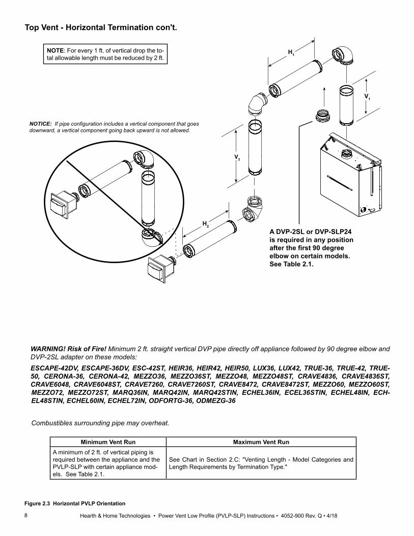
WARNING! Risk of Fire! Minimum 2 ft. straight vertical DVP pipe directly off appliance followed by 90 degree elbow and DVP-2SL adapter on these models: ESCAPE-42DV, ESCAPE-36DV, ESC-42ST, HEIR36, HEIR42, HEIR50, LUX36, LUX42, TRUE-36, TRUE-42, TRUE-50, CERONA-36, CERONA-42, MEZZO36, MEZZO36ST, MEZZO48, MEZZO48ST, CRAVE4836, CRAV-E4836ST, CRAVE6048, CRAVE6048ST, CRAVE7260, CRAVE7260ST, CRAVE8472, CRAVE8472ST, MEZZO60, MEZZO60ST, MEZZO72, MEZZO72ST, MARQ36IN, MARQ42IN, MARQ42STIN, ECHEL36IN, ECEL36STIN, ECHEL48IN, ECHEL48STIN, ECHEL60IN, ECHEL72IN, ODFORTG-36, ODMEZG-36Combustibles surrounding pipe may overheat.
8 Hearth & Home Technologies • Power Vent Low Profile (PVLP-SLP) Instructions • 4052-900 Rev. Q • 4/18
H1
H2
V2
V1
NOTICE: If pipe configuration includes a vertical component that goes downward, a vertical component going back upward is not allowed.
A DVP-2SL or DVP-SLP24 is required in any position after the first 90 degree elbow on certain models. See Table 2.1.
Figure 2.3 Horizontal PVLP Orientation
WARNING! Risk of Fire! Minimum 2 ft. straight vertical DVP pipe directly off appliance followed by 90 degree elbow and DVP-2SL adapter on these models: ESCAPE-42DV, ESCAPE-36DV, ESC-42ST, HEIR36, HEIR42, HEIR50, LUX36, LUX42, TRUE-36, TRUE-42, TRUE-50, CERONA-36, CERONA-42, MEZZO36, MEZZO36ST, MEZZO48, MEZZO48ST, CRAVE4836, CRAVE4836ST, CRAVE6048, CRAVE6048ST, CRAVE7260, CRAVE7260ST, CRAVE8472, CRAVE8472ST, MEZZO60, MEZZO60ST, MEZZO72, MEZZO72ST, MARQ36IN, MARQ42IN, MARQ42STIN, ECHEL36IN, ECEL36STIN, ECHEL48IN, ECH-EL48STIN, ECHEL60IN, ECHEL72IN, ODFORTG-36, ODMEZG-36
Combustibles surrounding pipe may overheat.
Top Vent - Horizontal Termination con't.
Minimum Vent Run Maximum Vent RunA minimum of 2 ft. of vertical piping is required between the appliance and the PVLP-SLP with certain appliance mod-els. See Table 2.1.
See Chart in Section 2.C: "Venting Length - Model Categories and Length Requirements by Termination Type."
NOTE: For every 1 ft. of vertical drop the to-tal allowable length must be reduced by 2 ft.

9 Hearth & Home Technologies • Power Vent Low Profile (PVLP-SLP) Instructions • 4052-900 Rev. Q • 4/18
C. Venting Length - Model Categories and Length Requirements by Termination Type The Model Category (0,1, 2 or 3) in Table 2.2 corresponds with the number in the shaded area of the Allowable Vent Length Chart In Table 2.3.
Table 2.2 Models
NOTE: See the PRIMO install manual (2310-970) for allowed vent configurations for the following SKUs: PRIMO48, PRIMO60, PRIMO72, PRIMO48ST, PRIMO60ST, PRIMO72ST.
These configurations are not allowed.
HEAT & GLO HEATILATOR MAJESTIC MAJESTIC MAJESTIC HHT HHT
Category 0 Category 0 &1 Category 0, 1 & 2 Category 0,1, 2 & 3
Category 0
Category 0 & 1
Category 0, 1 & 2
Category 0, 1, 2 & 3
Category 0 & 1
Category 0, 1 & 2
Category 0, 1, 2 & 3
Category 0,1 & 2
Category 0, 1, 2& 3
REVO-S21 SL-550TR, SL-750TR, SL-950TR
S L R - B S L R - C ,
COSMO41-IFTION-H7 RAVE3012I
NDV3630, NDV3933, NDV4236, NDV4842
RAVE4013i, RAVE4013-
IFT
JADE32IN DBDV36I, DBDV42I, DBDV36PLATI, DBDV42PLATI,MERID36, MERID42, MERIDPLA36, MERIDPLA42
MARQ36INMARQ42INMARQ42STIN
RCOR-DV36INLCOR-DV36IN
ODFORTG-36
REVO-H31 SL-350TRS, SL-550TRS, SL-750TRS RED40,
RED40ST
ION-S7 RAVE3012-IFT
CD4236, CD4236-IFTCD4842, CD4842-IFT
QUARTZ32I,QUARTZ36IQUARTZ42I
JADE42IN, JADE 42IL
ODMEZG-36
SLR32 6000C, 6000CL, 6000CLX, 6000BEC, 6000C-IFT, 6000CLX-IFT, 6000CL-IFT ALL ESC-42ST
CNXT4236, CNXT4842, CNXT4236-IFT, CNXT4842-IFT
COSMO32-IFT 8000C, 8000CL, 8000CLX,8000C-IFT, 8000CL-IFT,8000CLX-IFT
ESCAPE-36DVNEVO3630, NEVO4236
6000CMOD, 8000CMOD, 6000CMOD-IFT, 8000CMOD-IFT
ESCAPE-42DV DV3732
SL-550METRO, SL-550-BE-M ALL TRUE-36 GDST3831,
GDST4336, GDFL4136, GDCR4136, GDCL4136
ALL HEIR36,ALL HEIR42, ALL HEIR50
PEARL36PRINPEARL36STINST-36TR,ST-36TRB,PIER-
36TR, PIER-36TRB, LCOR-36TRB,RCOR-36TRB
ALL TRUE-42
ALL TRUE-50
MEZZO60, MEZZO60STMEZZO72, MEZZO72ST
ALLLUX36, LUX42
CRAVE4836, CRAVE4836ST CRAVE6048, CRAVE6048ST
ECHEL36IN,ECHEL36STINECHEL48IN,ECHEL48STIN
MEZZO36, MEZZO36ST, MEZZO48, MEZZO48ST
CERONA-36 CERONA-42
CRAVE7260,CRAVE7260ST,CRAVE8472,CRAVE8472ST
ECHEL60IN,ECHEL72IN
SL-550F, SL-5FSL-750F, SL-7F
NNXT3933NNXT4236
EVEREST ION-H7
SL-5, SL-7, SL-9 ECLIPSE-36
SL-3X, SL-5X, SL-7X, SL-9X
SL-3X-IFT, SL-5X-IFT, SL-7X-IFT, SL-9X-IFT
NOTE: The REVO-V12 AND ION-V7 are not approved for use with the PVLP-SLP.
►

10 Hearth & Home Technologies • Power Vent Low Profile (PVLP-SLP) Instructions • 4052-900 Rev. Q • 4/18
Horizontal TerminationTotal Venting Length (Feet) Includes both horizontal and vertical section of pipe
# of Elbows 10 20 30 40 50 60 70 80 90 100 110 120 130 1401 0 0 0 0 1 1 1 1 2 32 0 0 0 0 1 1 1 2 33 0 0 0 0 1 1 1 24 0 0 0 1 1 1 2 35 0 0 0 1 1 1 26 0 0 1 1 1 2 37 0 0 1 1 1 2 38 0 1 1 1 1 29 0 1 1 1 1 2
10 1 1 1 1 2 311 1 1 1 1 212 1 1 1 1 2
Table 2.3 Allowable Vent Runs - Horizontal Termination

11 Hearth & Home Technologies • Power Vent Low Profile (PVLP-SLP) Instructions • 4052-900 Rev. Q • 4/18
A. Framing and ClearancesChassis Dimensions The dimensions are measured as shown in Figure 3.1.
3 Framing and Clearances
Figure 3.1 Dimensions
14 in. [356mm]
15-1/2 in. [394mm]
[292mm] 11-1/2 in.
8 in. [203mm]
[112mm] 4-3/8 in. 5-1/4 in.
4-3/4 in.
2-1/4in. 10 in. [254mm] [135mm]
[57mm] 2-1/4in.
[57mm]
[121mm]
[241mm] 9-1/2 in.
12-1/2 in. [318mm]
[159mm] 6-1/4 in.
1-1/2 in. [38mm]
Front View Without Cover
Front View With Cover Side View
Back View
Top view
10 IN.
13 IN.Framing Dimensions1. Construct a framework as shown in Figure 3.2.
Framework material should be the same dimensions as the material used for the wall framing. The dimensions of the box must be 10 inches high by 13 inches wide.
2. Cut a 10 inch high by 13 inch wide opening into the exterior of the structure. Stay inside of the newly installed framing as shown in Figure 3.2.
Figure 3.2

12 Hearth & Home Technologies • Power Vent Low Profile (PVLP-SLP) Instructions • 4052-900 Rev. Q • 4/18
Roof Top Termination1. If the PVLP-SLP is going to terminate on a flat roof, an
enclosure similar to the one shown in Figure 3.4 will need to be constructed.
1 in.[25mm]
1-1/2 in.[38mm]
0
2 in.[51mm]
20-3/4 in.[527mm]
12 in.[305mm]
Figure 3.4
0 in.
0 in.
0 in.
0 in.
1 in.[25mm] to side of pipe
1 1/2 in.[38mm] to top of pipe
1 in.[25mm] to bottom of pipe
2 in.[51mm] to back of cap
Top View Side View
Clearance to Combustibles
Figure 3.3 Minimum Clearances
13 Hearth & Home Technologies • Power Vent Low Profile (PVLP-SLP) Instructions • 4052-900 Rev. Q • 4/18
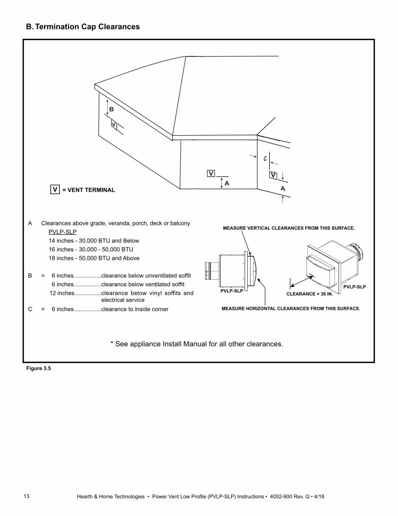
CLEARANCE = 36 IN.
MEASURE VERTICAL CLEARANCES FROM THIS SURFACE.
MEASURE HORIZONTAL CLEARANCES FROM THIS SURFACE.
PVLP-SLPPVLP-SLP
B
A
C
V
V
V
A
A Clearances above grade, veranda, porch, deck or balcony PVLP-SLP 14 inches - 30,000 BTU and Below 16 inches - 30,000 - 50,000 BTU 18 inches - 50,000 BTU and Above
B = 6 inches.................clearance below unventilated soffit 6 inches.................clearance below ventilated soffit 12 inches ................clearance below vinyl soffits and
electrical service C = 6 inches.................clearance to inside corner
V = VENT TERMINAL
B. Termination Cap Clearances
* See appliance Install Manual for all other clearances.
Figure 3.5

14 Hearth & Home Technologies • Power Vent Low Profile (PVLP-SLP) Instructions • 4052-900 Rev. Q • 4/18
Figure 3.6
B. Installing Vent Cap1. Remove the eight screws holding the back cover to the
cap. See Figure 3.6.2. Slide the exhaust housing assembly out of the back of
the cap. See Figure 3.7 and 3.8.3. Remove the four corrugated shipping pads. See Figure
3.9.4. Install PVI wiring harness through the electrical access
hole in back cover cap. See Figure 3.10.
Figure 3.7
Figure 3.8
Figure 3.9
Figure 3.10
NOTE: • The PVLP-SLP may be painted to a desired
color, as long as the paint selected has sufficient temperature and environmental ratings.
• Thoroughly sand the existing coating prior to painting with sand paper or steel wool.
• The front of the cap cover may be field-painted and cured up to 400 degrees Fahrenheit (204° C). All remaining parts of the cap may be painted but they may not be cured beyond 190 degrees Fahrenheit (88° C) due to gaskets and components overheating.
• Certain areas of the cap surface may reach up to 600 degrees Fahrenheit (316° C). Paints selected should have sufficient temperature ratings.
• Cap contains silicone sealant which could affect adherence of paint. Please advise local painter of silicone content.

15 Hearth & Home Technologies • Power Vent Low Profile (PVLP-SLP) Instructions • 4052-900 Rev. Q • 4/18
B. Installing Vent Cap (con't)
7. The air baffle is shipped in the closed position; for cer-tain vent runs the air baffle will need to be adjusted. To adjust the baffle, remove the locking screw. See Figure 3.15. (Refer to section 5B to determine baffle setting.)
Figure 3.13
Figure 3.14
Figure 3.11
Figure 3.12
6. Attach the white and black wires from the PVI harness to the two black wires coming from the blower. Attach the green wire from the PVI harness to the green/yellow wire coming from the blower. See figure 3.13.
NOTE: After all wires are connected, the wire should look like the picture in Figure 3.14.
Figure 3.15
Figure 3.16
5. Attached the red and brown wires to the pressure switch. See Figure 3.12.
NOTE: Make sure there is no more than 4 or 5 inches of wire extending through the back cap cover. See Figure 3.11.
8. To open the baffle, turn the adjustment bolt counter clockwise. See Figure 3.16.
CAUTION! Risk of overheating! The baffle must re-main fully closed when using PVLP-SLP with PRIMO models. See installation instructions for details and PRIMO48 exception.

16 Hearth & Home Technologies • Power Vent Low Profile (PVLP-SLP) Instructions • 4052-900 Rev. Q • 4/18
B. Installing Vent Cap (con't)
Figure 3.17
Figure 3.18
NOTE: Use a tape measure to measure the distance from the front cover to the flange on the air baffle. See Figure 3.17.
9. Reinstall the exhaust housing assembly into the cap after the wiring and baffle adjustment have been completed.
10. The front cover must be removed to access the mount-ing holes for the cap. Remove the four screws that attach the front cover, then remove the cover. See Figure 3.18.

17 Hearth & Home Technologies • Power Vent Low Profile (PVLP-SLP) Instructions • 4052-900 Rev. Q • 4/18
NOTICE: It is imperative that the PVLP-BEK kit be installed squarely or the PLVP-SLP may not fit into opening left once finishing has occurred. Also care should be taken to ensure that PVLP-BEK is secured flat to wall. 17. The wall is now ready to be finished. Finishing
materials such as stone, marble or brick can then be applied up to the flanges of the PVLP-BEK that protrude perpendicular to the wall. This will ensure that the cap will fit into the opening after finishing has been completed.
NOTICE Outside flanges of the PVLP-BEK must not have any pressure on them from the finishing materials. This could cause the opening left after finishing to be too small. 18. After PVLP-BEK has been installed and the finishing
of the wall has taken place, apply a bead of silicone (with a minimum of 300° F continuous exposure rating) to the PVLP-BEK around the entire metal flange, as shown in Figure 3.24 with the dotted line.
APPLY SILICONE (with a minimum of 300°F continu-ous exposure rating) TO FLANGE
OUTSIDE FLANGE (SECURE FIRST)
OUTSIDE FLANGE (SECURE FIRST)
APPLY SILICONE (with a minimum of 300°F continuous exposure rating) TO TOP CORNERS
APPLY SILICONE (with a minimum of 300°F continuous exposure rating) TO PERFO-RATED HOLES.
Figure 3.21 PLVP-BEK Attached to Wall
Figure 3.19 Bend BEK Sections
RETURN BEND ON SECTION A LOCATED ON OUTSIDE OF SECTION B.
SECTION A
SECTION B
SECURE TO BUILDING EXTERIOR USING TOP (2) AND BOTTOM (2) MOUNTING HOLES
Figure 3.20 BEK Assembled
11. Assemble the PVLP-BEK kit. Bend the two sections of the PVLP-BEK kit as shown in Figure 3.19.
12. Use the supplied screws to assemble the box as shown in Figure 3.20. The return bend on section A should be located on the outside of section B.
13. Place assembled box over the framed opening in the wall with outside flanges oriented vertically and held tight to the building exterior. See Figure 3.21.
NOTE: A PVLP-BEK kit will be needed for installations with exterior finishing materials greater than 1 in. thick. Order with the appliance and venting system. It will be used to ensure that the finishing is done to the appropriate size for the low profile power vent (PVLP) to be installed properly.
If installing with finishing material less than 1 inch thick, proceed to step 22.
14. Drive two of the supplied screws through opposite ends of the two outer flanges. This will secure the PVLP-BEK extension box to the building and allow for squaring of the PVLP-BEK. See Figure 3.21.
15. Seal all corners, joints and bend lines with silicone (with a minimum of 300° F continuous exposure rating) caulk. Ensure all gaps and holes are filled so a sealed envelope is formed.
16. If finishing material extends past the cap extension box (BEK) more than one inch, an additional BEK is required. Cap extension boxes may be stacked for thicker wall applications:• Attach first box to the wall.• Assemble second box.• Bend the two outside flanges of the second box
around to the inside of the box.• Secure the second box to the first using four #8 x 1/2
sheet metal screws.

18 Hearth & Home Technologies • Power Vent Low Profile (PVLP-SLP) Instructions • 4052-900 Rev. Q • 4/18
SECURE TO BUILDING EXTERIOR USING TOP (2) AND BOTTOM (2)
MOUNTING HOLES BEK
Figure 3.22 SLP-LPC Attached to LPC-BEK
Figure 3.24
Figure 3.25
Figure 3.26
21. Place decorative cover onto cap and fasten. Once cover has been secured, installation is complete.
22. Place a bead of silicone (with a minimum of 300° F continuous exposure rating) on the back side of the mounting flange for the cap. See Figure 3.24.
23. Install the cap into the wall and attach the cap to the wall using the eight screws provided. See Figure 3.25.
NOTE: Be careful not to tear the gasket on the mounting flange.
24. Once the cap is fastened to the wall, apply a bead of silicone around the cap base. See Figure 3.26.
25. Reinstall the cap cover using the four scews removed earlier.
SILICONE (with a minimum of 300°F
continuous exposure rating)
(ALL 4 SIDES)
SILICONE (with a minimum of 300°F continuous exposure rating)
(ALL 4 SIDES)
FINISHING MATERIAL5 IN. MAXIMUM
BEKPVLP-SLP
Figure 3.23 Silicone Weather Sealing
20. After the PVLP-SLP has been secured to the PVLP-BEK, silicone (with a minimum of 300° F continuous exposure rating) should be applied around outer edge of PVLP-BEK where it meets the building exterior. Silicone (with a minimum of 300° F continuous exposure rating) should also be applied where PVLP-SLP and PVLP-BEK meet, as shown in Figure 3.23.
19. Apply a bead of silicone (with a minimum of 300° F continuous exposure rating) around the entire metal flange of the PVLP-SLP. See Figure 3.24. Align with PVLP-BEK as shown in Figure 3.22. Ensure cap is level and square, then secure PVLP-SLP to PVLP-BEK as shown in Figure 3.23.

19 Hearth & Home Technologies • Power Vent Low Profile (PVLP-SLP) Instructions • 4052-900 Rev. Q • 4/18
A. Wiring the Appliance for the PVLP-SLP with IntelliFire™ and IntelliFire™ Plus (IPI) Controls
NOTICE: The 8K1-PVI control module must be used to integrate the PVLP-SLP to the fireplace. (The 8K1-PVI is included with the PV-IPI-CK which is sold separately. When installing the PVLP-SLP on PRIMO models the 8K1-PVI is included with the fireplace.)
NOTICE: Electrical wiring must be done in accordance with national, provincial, and/or local electric codes.CAUTION! Risk of shock! Disconnect electrical power from fireplace/power vent before performing any mainte-nance, repair, or electrical wiring.NOTICE: Electrical service of 120 VAC-60Hz must be supplied to the junction box of the fireplace in order for the power vent to operate correctly.
4 Electrical Information
TO JUNCTION BOX (110V)
MODULE
FLAME SENSE IGNITER
GROUND
ORANGE(PILOT)
GREEN(MAIN)
BROWN
BLACKRED
BATTERY PACK6V DC (AA X 4)
THERMOSTAT WIRE ASSEMBLY / WALL
SWITCH WIRE
STEP 2
STEP 1
STEP 4
STEP 5
STEP 3
STEP 7
STEP 6
Figure 4.1 IntelliFire Plus™ (Black) IPI Module Wiring as Shipped from Factory
REMOVAL OF UNNECESSARY PARTSRefer to the appropriate directions depending on the color of the IPI module (Black or Green.) IntelliFire Plus™ IPI Module (Black)Refer to Figure 4.1 for steps 1 through 7. The shaded portion corresponding to the numbered step is the task to be performed.1. Unplug control module power.2. Detach the white and orange wires from the control
module.3. Detach the remaining harnesses from the control mod-
ule.4. Remove the black control module. This will no longer
be needed.5. Remove and discard battery pack (if present).6. Unplug wall switch wires (if present).7. Remove and discard IPI wire harness.
NOTICE: When installing the power vent with the MEZZO, ECHELON and CRAVE models, the LED will need to be disconnected from the AUX2 (factory setting) and moved to AUX1. Plug the power vent system into AUX2. The LED function will only be operational on the HIGH setting.

20 Hearth & Home Technologies • Power Vent Low Profile (PVLP-SLP) Instructions • 4052-900 Rev. Q • 4/18
STEP 1
PLUG-IN
REMOTEJUMPER WIRE
ORG
GR
N
BR
N
BR
N
RED
BLK
INTERMITTENTPILOT IGNITOR
ORG
WHT
IGNITION MODULE 3 VAC
TRANSFORMER
VALVE
3 VAC
THERMOSTATWIRE
ASSEMBLY
STEP 3
STEP 2
STEP 5 STEP 4
STEP 6
Figure 4.2. IntelliFire™ (Green) IPI Module Wiring as Shipped from Factory
IntelliFire™ IPI Module (Green)Refer to Figure 4.2 for steps 1 through 6.1. Remove and discard wire harness connecting the valve
to the control module. 2. Unhook the 3V transformer and discard. This will no
longer be used.3. Remove and discard battery pack (if present).4. Detach the white and orange wires from the control
module.5. Remove the green control module. This will no longer
be used.6. Unplug wall switch wires (if present).
21 Hearth & Home Technologies • Power Vent Low Profile (PVLP-SLP) Instructions • 4052-900 Rev. Q • 4/18
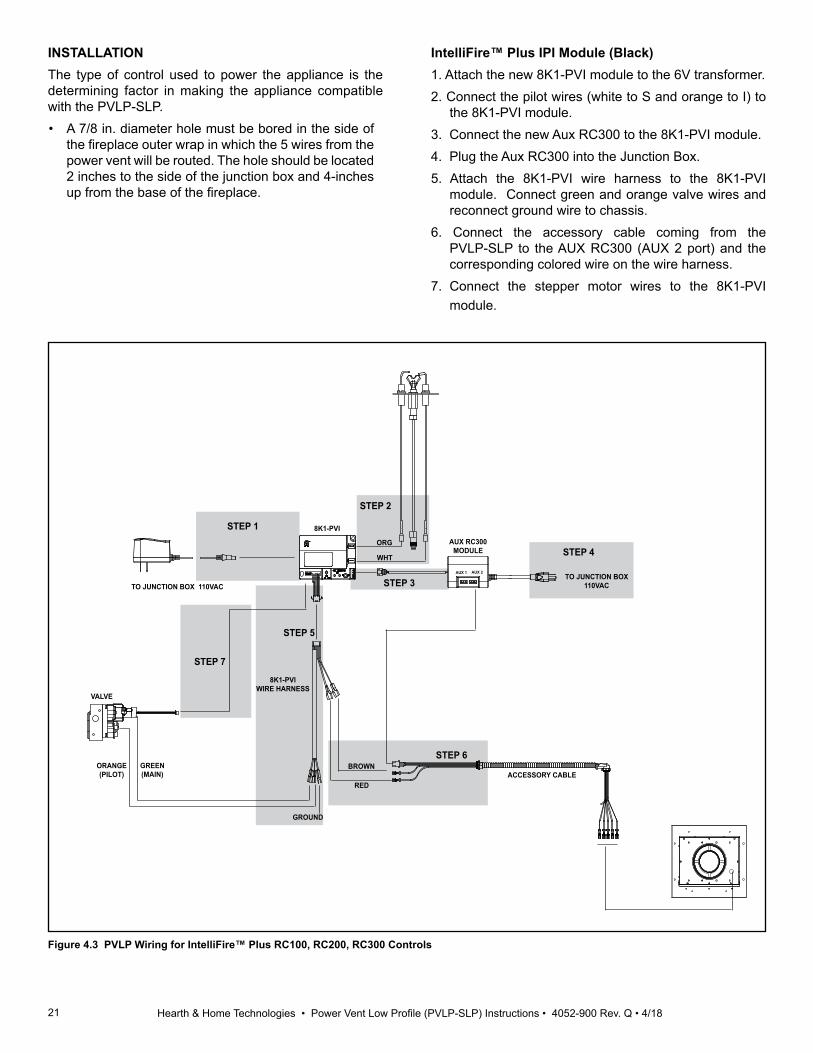
INSTALLATIONThe type of control used to power the appliance is the determining factor in making the appliance compatible with the PVLP-SLP. • A 7/8 in. diameter hole must be bored in the side of
the fireplace outer wrap in which the 5 wires from the power vent will be routed. The hole should be located 2 inches to the side of the junction box and 4-inches up from the base of the fireplace.
IntelliFire™ Plus IPI Module (Black)1. Attach the new 8K1-PVI module to the 6V transformer.2. Connect the pilot wires (white to S and orange to I) to
the 8K1-PVI module.3. Connect the new Aux RC300 to the 8K1-PVI module.4. Plug the Aux RC300 into the Junction Box.5. Attach the 8K1-PVI wire harness to the 8K1-PVI
module. Connect green and orange valve wires and reconnect ground wire to chassis.
6. Connect the accessory cable coming from the PVLP-SLP to the AUX RC300 (AUX 2 port) and the corresponding colored wire on the wire harness.
7. Connect the stepper motor wires to the 8K1-PVI module.
STEP 4
VALVE
ORANGE(PILOT)
GREEN(MAIN)
GROUND
WHT
AUX RC300MODULE
AUX 1 AUX 2
8K1-PVI
TO JUNCTION BOX 110VAC
ACCESSORY CABLE
ORG
TO JUNCTION BOX110VAC
8K1-PVIWIRE HARNESS
BROWN
RED
STEP 1
STEP 2
STEP 3
STEP 5
STEP 6
STEP 7
Figure 4.3 PVLP Wiring for IntelliFire™ Plus RC100, RC200, RC300 Controls
22 Hearth & Home Technologies • Power Vent Low Profile (PVLP-SLP) Instructions • 4052-900 Rev. Q • 4/18
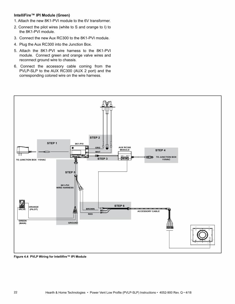
IntelliFire™ IPI Module (Green)1. Attach the new 8K1-PVI module to the 6V transformer.2. Connect the pilot wires (white to S and orange to I) to
the 8K1-PVI module.3. Connect the new Aux RC300 to the 8K1-PVI module.4. Plug the Aux RC300 into the Junction Box.5. Attach the 8K1-PVI wire harness to the 8K1-PVI
module. Connect green and orange valve wires and reconnect ground wire to chassis.
6. Connect the accessory cable coming from the PVLP-SLP to the AUX RC300 (AUX 2 port) and the corresponding colored wire on the wire harness.
STEP 4
GROUND
WHT
AUX RC300MODULE
AUX 1 AUX 2
8K1-PVI
TO JUNCTION BOX 110VAC
ACCESSORY CABLE
ORG
TO JUNCTION BOX110VAC
8K1-PVIWIRE HARNESS
BROWN
RED
STEP 1
STEP 2
STEP 3
STEP 5
STEP 6VALVE
ORANGE(PILOT)
GREEN(MAIN)
Figure 4.4 PVLP Wiring for Intellifire™ IPI Module

23 Hearth & Home Technologies • Power Vent Low Profile (PVLP-SLP) Instructions • 4052-900 Rev. Q • 4/18
RED
GREEN
BLACK
NOTE: Use threaded nut to secure accessory cable to power vent.
WHITE
BROWN
BLOWER
TO PVI CONTROL
VACUUM SWITCH
Figure 4.5 Internal PVI Wiring

24 Hearth & Home Technologies • Power Vent Low Profile (PVLP-SLP) Instructions • 4052-900 Rev. Q • 4/18
B. Wiring the Appliance for the PVLP-SLP with IntelliFire™ Touch (IFT) Controls
NOTICE: When integrating the PVLP-SLP onto an ap-pliance with IntelliFire™ Touch (IFT) controls, the RC400 remote control and the Auxiliary Control Module (IFT-ACM) must be equipped on the appliance. The IFT-RC400 includes the RC400 and the IFT-ACM. The IFT-ACM is available separtely for appliances already equipped with the RC400 remote control.
NOTICE: Electrical wiring must be done in accordance with national, provincial, and/or local electric codes.
CAUTION! Risk of shock! Disconnect electrical power from fireplace/power vent before performing any mainte-nance, repair, or electrical wiring.NOTICE: Electrical service of 120 VAC-60Hz must be supplied to the junction box of the fireplace in order for the power vent to operate correctly.
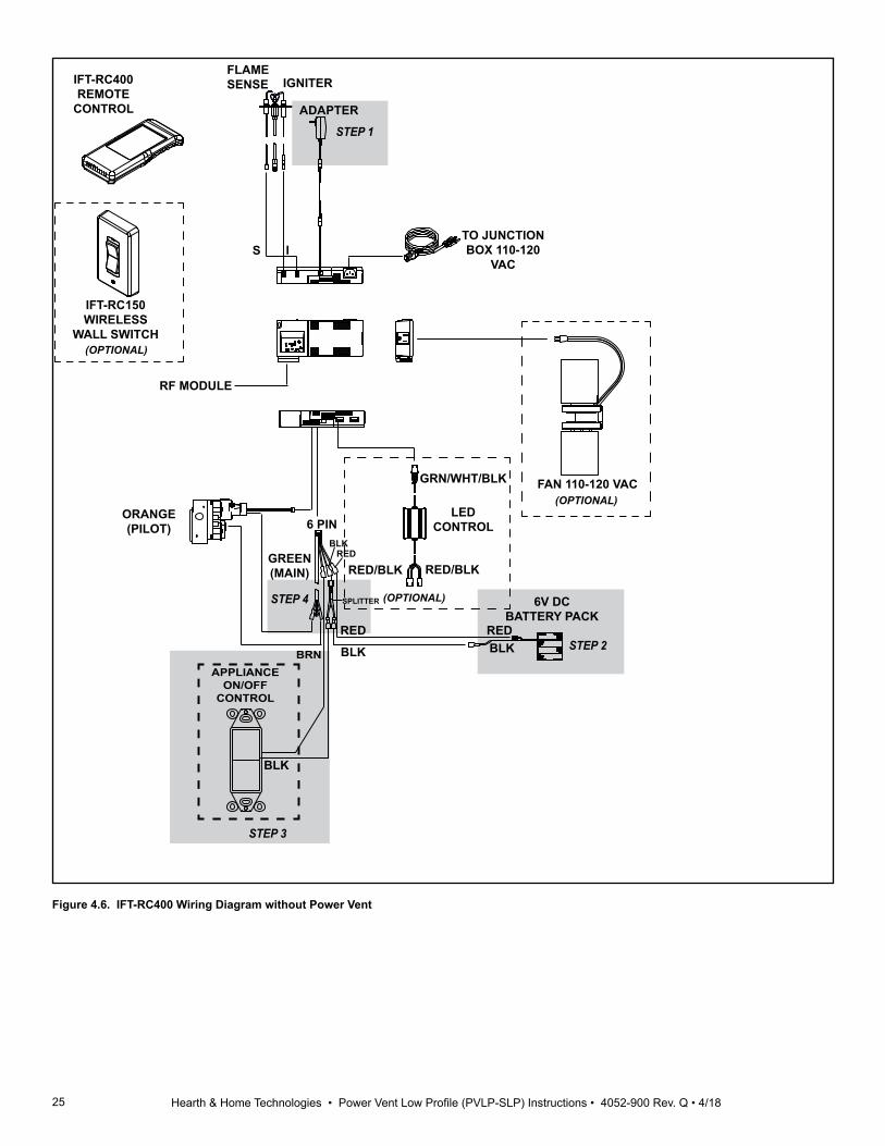
REMOVAL OF UNNECESSARY PARTSRefer to Figure 4.6 for steps 1 through 4. Some features may or may not exist on appliance. The shaded portion corresponding to the numbered step is the task to be performed.1. Unplug control module power.2. Remove and discard battery pack (if present).3. Detach wires from 6 pin harness that connect an op-
tional appliance on/off control (if present) and discard.4. Remove jumper/splitter wire (if present) and discard.
WARNINGRisk of Fire! Explosion
Hazard!
Failure to follow instructions could result in a fire or explosion.
• Power Vent must be paired to IFT-ACM before installation is complete.
• If you have 120 VAC Power & Gas to applance: - Immediately after connecting the PVI-WH connector to the IFT-ACM, the IFT control must be paired to recognize the Power Vent as part of the control configuration.
- Appliance and Power Vent function must be verified before installation is complete. - Consult installation manuals for details.
• If you DO NOT have 120 VAC Power & Gas: - DO NOT connect PVI-WH connector to IFT- ACM. - Disconnect 6V power to lock-out appliance.
25 Hearth & Home Technologies • Power Vent Low Profile (PVLP-SLP) Instructions • 4052-900 Rev. Q • 4/18
FLAME SENSE IGNITER
TO JUNCTION BOX 110-120
VAC
FAN 110-120 VAC
LED CONTROL
RF MODULE
IS
BRN
ORANGE(PILOT)
IFT-RC400REMOTE
CONTROL
GRN/WHT/BLK
RED/BLK
IFT-RC150WIRELESS
WALL SWITCH(OPTIONAL)
(OPTIONAL)
SPLITTER
BLKRED
ADAPTER
6V DC BATTERY PACK
BLKRED
6 PIN
BLKRED
GREEN(MAIN) RED/BLK
(OPTIONAL)
APPLIANCE ON/OFF
CONTROL
BRN
BLK
STEP 1
STEP 2
STEP 4
STEP 3
Figure 4.6. IFT-RC400 Wiring Diagram without Power Vent

26 Hearth & Home Technologies • Power Vent Low Profile (PVLP-SLP) Instructions • 4052-900 Rev. Q • 4/18
Installation Steps:If the appliance is equipped with an IFT-ACM, proceed to step 10. If not, proceed to next step.
5. Locate the IntelliFire™ Touch electronic control module (IFT-ECM) in the control cavity of the appliance and move the three-position switch to the OFF position. See Figure 4.7.
6. Remove protective rubber cap from connector on the top of the IFT-ECM. See Figure 4.7.
Figure 4.7. IFT-ECM
8. Connect the IFT-ACM to the IFT-ECM by aligning the pins and tabs and pushing the IFT-ACM into the IFT-ECM until both tabs latch in place. Ensure the IFT-ECM and IFT-ACM are aligned with each other and fastened securely. See Figure 4.8.
Figure 4.8. Connecting IFT-ACM and IFT-ECM
WARNING! Risk of Shock! DO NOT touch male pins. Leave rubber cap on all ports unless port is being con-nected to a load.
9. The IFT-ACM can provide power to HHT approved options including fan, lights and power vent.
• To connect a fan kit to the IFT-ACM, insert the three prong male plug from the fan into the re-ceptacle located on the right side of the IFT-ACM. See Figure 4.9.
• To connect a light kit to the IFT-ACM, remove pro-tective rubber cap labeled ‘LIGHTS’ and connect to the female cord that was supplied in your lights kit into the three male pins on the IFT-ACM. See Figure 4.9.
• To connect a power vent kit to the IFT-ACM, re-move protective rubber cap labeled ‘AUX’ and connect to the female cord of the PVI-WH wire harness into the three male pins on the IFT-ACM. See Figure 4.9.
Figure 4.9. Fan, Lights and Power Vent Connection
WARNING! Risk of Shock! DO NOT touch male pins. Leave rubber cap on all ports unless port is being con-nected to a lead.
POWER CORD
FAN
POWERVENT
LIGHTS
10. Refer to wiring diagram with Power Vent to make re-maining connections. See Figure 4.10.
7. Attach velcro included with the IFT-ACM to the bottom of the ACM. See Figure 4.8.
ATTACH VELCRO
NOTE: It will be necessary to re-pair the remote after installing HHT approved options to the appliance. Refer to Section 4C for pairing the remote.
27 Hearth & Home Technologies • Power Vent Low Profile (PVLP-SLP) Instructions • 4052-900 Rev. Q • 4/18
STEP 13
STEP 11
STEP 12
STEP 14
BRN
FLAME SENSE IGNITER
TO JUNCTION BOX 110-120
VAC
FAN 110-120 VAC
LED CONTROL
RF MODULE
ADAPTER
IS
6 PIN
RED
BLK
ORANGE(PILOT)
GREEN(MAIN)
GRN/WHT/BLK
RED/BLK
RED/BLK
(OPTIONAL)
(OPTIONAL)
IFT-RC400REMOTE
CONTROL
REDBLK
BRN BRN
JUMPER WIRE
WIRE ASSEMBLY
MODULE RESET
SWITCH
(OPTIONAL ON SOME MODELS ONLY)
ACCESSORY CABLE
PVLPPOWER VENT
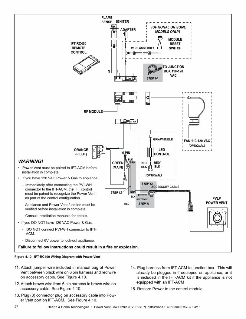
Figure 4.10. IFT-RC400 Wiring Diagram with Power Vent
11. Attach jumper wire included in manual bag of Power Vent between black wire on 6 pin harness and red wire on accessory cable. See Figure 4.10.
12. Attach brown wire from 6 pin harness to brown wire on accessory cable. See Figure 4.10.
13. Plug (3) connector plug on accessory cable into Pow-er Vent port on IFT-ACM. See Figure 4.10.
14. Plug harness from IFT-ACM to junction box. This will already be plugged in if equipped on appliance, or it is included in the IFT-ACM kit if the appliance is not equipped with an IFT-ACM
15. Restore Power to the control module.
• Power Vent must be paired to IFT-ACM before installation is complete. • If you have 120 VAC Power & Gas to applance: - Immediately after connecting the PVI-WH connector to the IFT-ACM, the IFT control must be paired to recognize the Power Vent as part of the control configuration.
- Appliance and Power Vent function must be verified before installation is complete. - Consult installation manuals for details.
• If you DO NOT have 120 VAC Power & Gas: - DO NOT connect PVI-WH connector to IFT- ACM. - Disconnect 6V power to lock-out appliance.
Failure to follow instructions could result in a fire or explosion.
WARNING!

28 Hearth & Home Technologies • Power Vent Low Profile (PVLP-SLP) Instructions • 4052-900 Rev. Q • 4/18
C. Pairing or Re-pairing the IFT-RC400 to the Electronic Control Module (IFT-ECM)
WARNING! After installation of Power Vent components, the RC400 and IFT-ECM MUST BE Re-Paired for safe operation.
CAUTION! Risk of Burns! DO NOT program the IFT Remote Controls to the IFT-ECM when flame or cold climate fuction is on or when appliance is hot.
1. On the IFT-ECM, move the ON/OFF/REMOTE switch to the REMOTE position. The green LED will blink three times. A few seconds later, an audible “beep” will occur to indicate that the system is ready.
NOTE: If the green LED continues to blink slowly (system is searching for a clear channel), wait until it stops before proceeding to step 2.
2. Locate the pairing hole on the IFT-ECM. See Figure 4.11. Using a paper clip or similar item, press and release the pairing button. The IFT-ECM will “beep” once and the green LED will blink for 14 seconds. During the 14 seconds, it is normal for installed accessories such as lights, fan, and Power Vent to energize momentarily.
While the green LED on the IFT-ECM is blinking, tap anywhere on the gray indicator bar located at the top of the IFT-RC400 screen. Tap on the pairing function as shown in Figure 4.12. If the IFT-RC400 has been paired successfully to the IFT-ECM, a double audible ‘beep” will be heard from the IFT-ECM.
NOTE: If the RC400 displays the 'Now pairing remote to product' display as shown below before able to reach the diagnostic menu on remote, you must repeat the process as follows;
A. Remove one battery from the RC400. B. Press the pairing button on the IFT-ECM. C. Quickly install the battery into the RC400. D. As soon as the main screen appears, tap on the
RC400 gray indicator bar. Then immediately tap the pairing icon. Successful pairing will be indicated by a double beep from the IFT-ECM.
3. If the pairing is unsuccessful, repeat steps 1 & 2.
Figure 4.11. Pairing IFT-ECM
REMOTE POSITION
PAIRING HOLE
GREEN LED
Figure 4.12. IFT-RC400 Wall Mount / Pairing Screen
NOTE: Refer to Operating Guide and Troubleshoot-ing Section of IFT-RC400 Installation Manual for Operation and Maintenance Sections of Remote Control.
NOTE: If additional components are added such as blowers, lights or Power Vent after initial pairing, the pairing process must be repeated again to detect additional components.

29 Hearth & Home Technologies • Power Vent Low Profile (PVLP-SLP) Instructions • 4052-900 Rev. Q • 4/18
A. Installation Inspection1. Follow safety inspection procedures recommended by
national, provincial, and/or local codes.2. Be certain all electrical connections are properly made
and secure.3. Visually inspect the vent system and determine that
there is no flue gas spillage, blockage or restriction, leakage, corrosion or other unsafe deficiencies.
5 Operating Instructions
Distance from PVLP-SLP to Appliance
Maximum AllowableBaffle Setting
2-15 ft. 2.5 in. open16-39 ft. 1.5 in. open
Greater than 40 ClosedTable 5.1.
B. Setting the PVLP-SLP Baffle Adjustment
CAUTION! Risk of electrical shock! DO NOT allow 120VAC wires to contact hot metal surfaces. Use sup-plied wire ties to bundle wires away from flue pipe, fan housing and other metal surfaces.
CAUTION! Risk of overheating! The baffle must remain fully closed when using PVLP-SLP with PRIMO models.
NOTE: The air baffle may be adjusted after installation. The baffle adjustment screw can be accessed by remov-ing the front cap cover.
• If the burner flames are short, active, and jumping – turn the bolt counter-clockwise (open). Check the burner flames and adjust the baffle again as necessary until the flames are stable, strong, and steady.
• If the burner flames are tall, lifting, floating, and ghost-like, the baffle is too open and MUST be closed (turn bolt clockwise).
• If the pilot continously sparks and does not become steady, the baffle may need to be opened. The requirements in Table 5.1 must still be met.
C. Power Vent Operating InstructionsAfter installation of the power vent, follow the operation instructions below for the type of control system/remote control used (IPI Plus/RC300, IFT/RC400/RC150.
IPI Plus/RC3001. Turn the remote "ON".
NOTE: During the period of operation after turning the fireplace "ON", there will be a delay (approx. 120 seconds) before the fireplace ignites. This is due to the time neces-sary for the fan to reach operating speed and to remove any gases from the combustion chamber. 2. After turning the remote to the "ON" position, if the fire-
place does not turn on, turn the remote to "OFF" refer to the troubleshooting section.
3. Turn the remote to "OFF" to turn off the burner. The power vent will continue to run for 20 minutes.
IFT/RC4001. Touch screen on RC400 to wake up. 2. Touch 'Turn Flame On'.3. Observe touch screen - if system is configured properly
for Power Vent Operation, a 2 min countdown timer will be displayed next to 'Turn Flame OFF'. See Figure below.
CORRECT PV DISPLAY INCORRECT PV DISPLAY
4. If the RC400 display is correct, the Power Vent will be running and the 2-minute countdown timer will run, after which the pilot will ignite followed by the main burner.
5. Touch 'Turn Flame OFF' on the RC400. The pilot and main will extinguish. The Power Vent will continue to run for 20 min.
If RC400 display is incorrect, touch 'Turn Flame OFF' and refer to troubleshooting section.
WARNING! After installation of Power Vent components, the RC400 and IFT-ECM MUST BE re-paired for safe operation.
30 Hearth & Home Technologies • Power Vent Low Profile (PVLP-SLP) Instructions • 4052-900 Rev. Q • 4/18
D. MaintenanceWARNING! Risk of Shock! Before performing any main-tenance or repair to the power vent assembly, make sure electrical power is disconnected to the fireplace.1. Vent System: Inspect all components and connections
annually. Replace, seal, or tighten pipe connections if necessary.
2. Motor: The fan motor bearings are sealed and no further lubrication is necessary. To access the motor, vacuum switch or pressure sense tube, refer to Section 5.E.
Figure 5.1
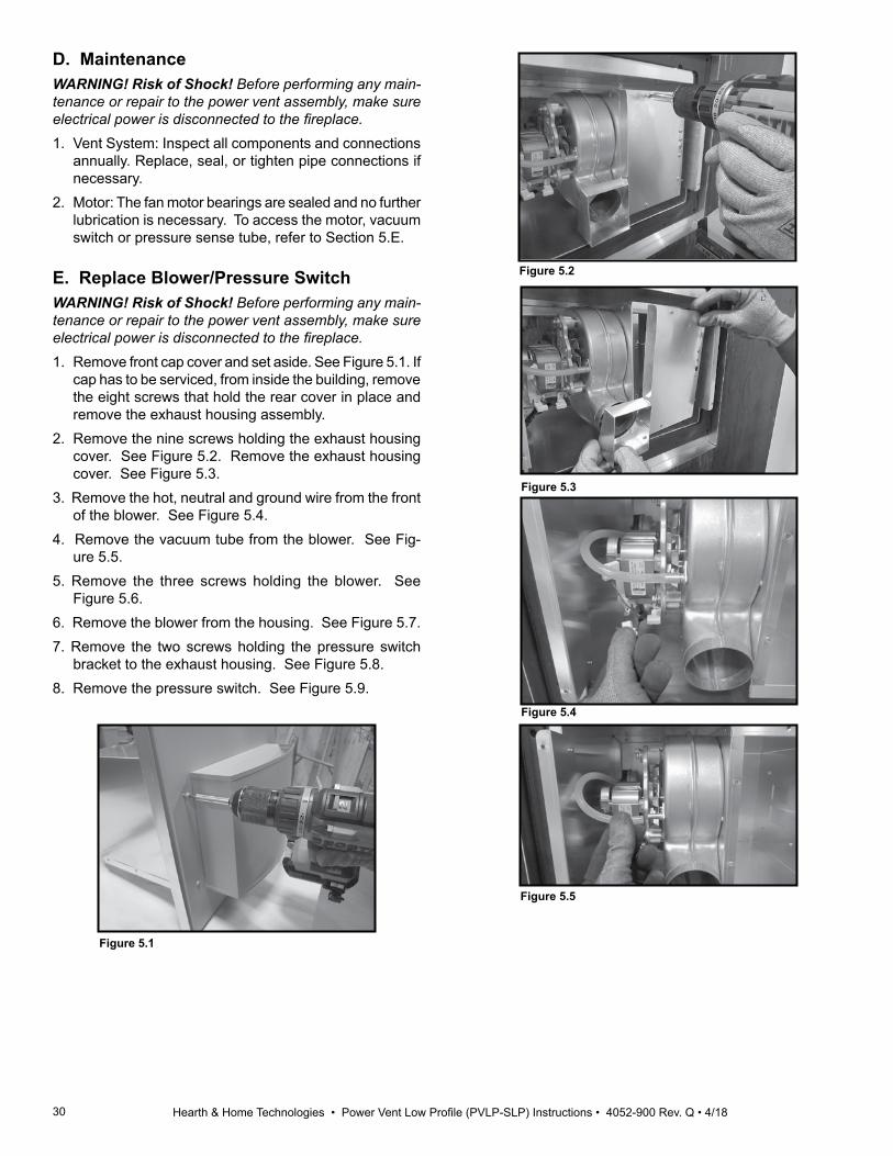
Figure 5.2E. Replace Blower/Pressure SwitchWARNING! Risk of Shock! Before performing any main-tenance or repair to the power vent assembly, make sure electrical power is disconnected to the fireplace.1. Remove front cap cover and set aside. See Figure 5.1. If
cap has to be serviced, from inside the building, remove the eight screws that hold the rear cover in place and remove the exhaust housing assembly.
2. Remove the nine screws holding the exhaust housing cover. See Figure 5.2. Remove the exhaust housing cover. See Figure 5.3.
3. Remove the hot, neutral and ground wire from the front of the blower. See Figure 5.4.
4. Remove the vacuum tube from the blower. See Fig-ure 5.5.
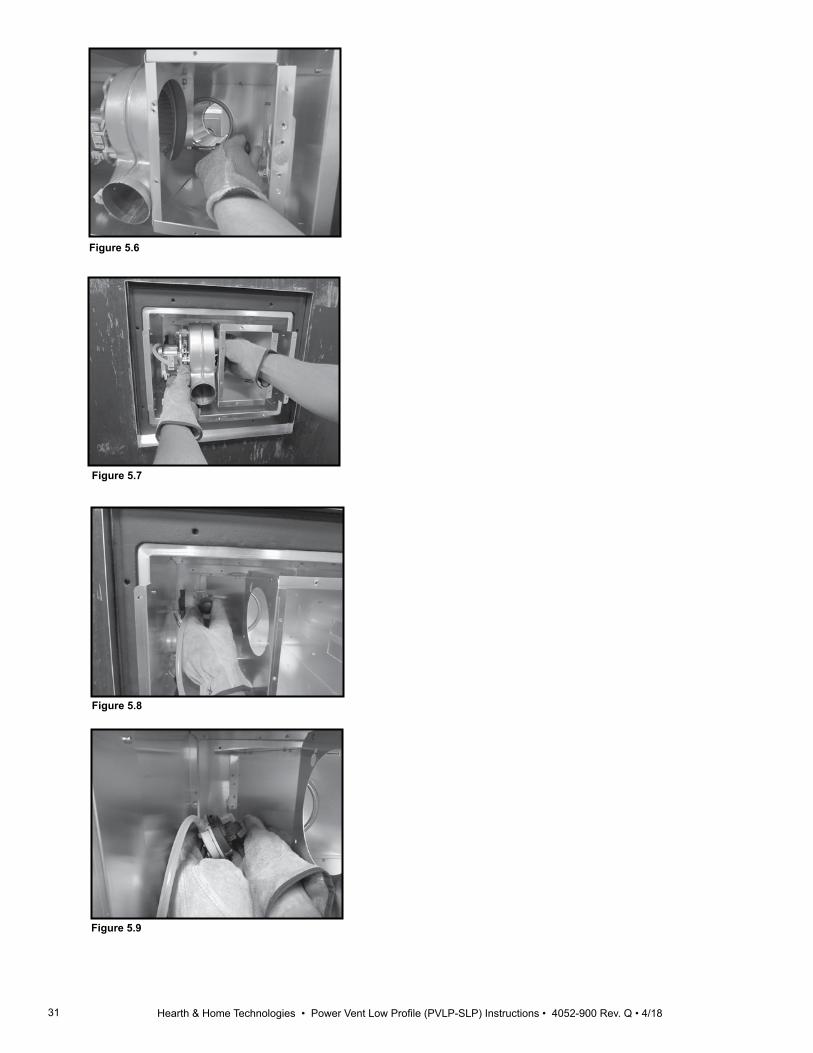
5. Remove the three screws holding the blower. See Figure 5.6.
6. Remove the blower from the housing. See Figure 5.7.7. Remove the two screws holding the pressure switch
bracket to the exhaust housing. See Figure 5.8.8. Remove the pressure switch. See Figure 5.9.
Figure 5.3
Figure 5.4
Figure 5.5
31 Hearth & Home Technologies • Power Vent Low Profile (PVLP-SLP) Instructions • 4052-900 Rev. Q • 4/18
Figure 5.6
Figure 5.7
Figure 5.8
Figure 5.9

32 Hearth & Home Technologies • Power Vent Low Profile (PVLP-SLP) Instructions • 4052-900 Rev. Q • 4/18
SymptomsPossible Causes Corrective Action
IntelliFire™ Plus System
Main Closes/ Pilot open, 5 seconds later pilot sparking with Blower ON. If condition persists for 60 seconds, 8K-1 locks out with 3 LED alarm.
Pilot Rectification Failure 1. Verify that black wire on IPI wire harness is prop-erly grounded to the fireplace chassis.
2. Verify that pilot is not being compromised by draft such that it fails to rectify. With the glass as-sembly in place, verify that the pilot flame is en-gulfing the flame sensing rod on the left side of the pilot hood. With a multi-meter, verify that the current in series between the module and the sense lead is at least 0.14 microamps.
3. Verify that line inlet pressure is within range on rating plate and correct pilot orifice is in pilot.
4. If #1-4 are correct, replace IPI module.
Pilot and Main shut down and 8K1-PVI locks out with 4, 5, or 6 LED alarm.
Blocked Flue/Insufficient Draft 1. Verify the teflon pressure tube is connected be-tween blower impeller housing and vacuum switch.
2. Verify that wiring within PVLP-SLP is correct and that the blower operates during the ignition com-mand.
3. Verify that the venting is connected and sealed properly.
4. Verify that the vent termination is not blocked. 5. If #1 thru #4 are complete, connect black and red
wires to bypass vacuum switch. If malfunction is corrected, lock-out system until the vacuum switch can be replaced.
Main Closes, 5 seconds later pilot sparking with Blower ON. If condition persists for 60 seconds, 8K-1 locks out with 3 LED alarm.
Shorted Pilot Sense 1. Verify that the white sensor lead is properly connected to the S-terminal on the module. 2. Check for soot deposits on the pilot sense rod, adjacent shielding, or logs. If so, clean affected parts. 3. Verify that the white sense lead from the pilot is not damaged or melted within the firebox or valve compartment. Replace pilot if damage exists.
Main Closes, 5 seconds later pilot sparking with Blower ON. If condition persists for 60 seconds, 8K-1 locks out with 3 LED alarm.
Disconnected Pilot Sense Verify that white sensor lead is properly connected to the S-terminal and the orange ignitor lead is con-nected to the I-terminal on the module
If given ignition command in both ON and RE-MOTE modes, system immediately locks-out with 3 LED alarm. Does not spark or attempt to ignite.
Pre-Existing/False Pilot Flame Check for pre-existing pilot flame. If so, the valve is defective and should be replaced.
Pilot rectifies, burner begins to light, but has a difficult time fully lighting.
Draft from back of firebox is too strong due to power vent.
Make sure air baffle is properly adjusted. If it is ad-justed properly, place ember material along the back side of the ports that are experiencing the difficult lighting. This will block a portion of the strong draft.
F. PVLP-SLP Troubleshooting

33 Hearth & Home Technologies • Power Vent Low Profile (PVLP-SLP) Instructions • 4052-900 Rev. Q • 4/18
Please contact your Hearth & Home Technologies dealer with any questions or concerns.
For the location of your nearest Hearth & Home Technologies dealer,
please visit www.hearthnhome.com.
Hearth & Home Technologies 7571 215th Street West, Lakeville, MN 55044
www.hearthnhome.com
Symptoms Possible Causes Corrective Action
System will not respond to ‘ON’ command. IFT-ECM in lockout with 5 RED:1 GREEN LED Error Code. RC400 shows ‘Call Dealer - Power Vent Error’ Message
1. Power Vent Motor Failure 2. Power Vent Over Heating 3. Power Vent Pressure Switch Open 4. Blocked Flue 5. Insufficient Draft 6. IFT-ECM selector switch in ‘ON’ Mode 7. IFT-ECM not paired to remote and
Power Vent,
1. Verify that the wiring within the Power Vent is correct. Verify that the PVI-SLP Cord assembly is correctly connected to the IFT switch wires, and the AUX port on the IFT-ACM.
2. Verify that blower operates during ‘ON’ com-mand.
3. Verify that the PVI-SLP is correctly installed such that it is properly vented and will not over-heat.
4. Verify that venting is connected and sealed properly. Verify termination is not blocked.
5. Verify the Teflon tube between the blower and pressure switch is securely connected.
6. Verify that the ‘ON’ command is provided with IFT-ECM in ‘REMOTE’ mode with approved re-mote control.
7. Re-pair the ECM to the Power Vent.
System responds to ‘ON’ command. After PVI-SLP completes 60 second pre-purge, IFT system fails to rectify proven pilot flame. IFT-ECM in lockout with 3 RED:1 GREEN LED. RC400 shows ‘Call Dealer - Appliance safety disabled’ Message
Pilot Rectification Failure resulting from:
1. Soot or embers contaminating pilot and burner
2. Shorted/melted pilot white ‘S’ sensor wire3. Disconnected pilot white ‘S’ sensor wire4. Excessive draft turbulence acting on the
pilot flame5. Oxidation or resistance on the IPI pilot
flame sense electrode6. Supply gas pressure out of specification
1. Verify that the IPI Pilot is clean. If necessary, remove any soot or ember deposits, and clean/polish flame sensor electrode with fine steel wool. If sooting is present, determine possible causes to correct issue.
2. Verify that the IPI pilot white ‘S’ wire is securely connected to the IFT-ECM, and is not melted/pinched/shorted along its length. Replace pilot is damage exists.
3. Verify that the gas supply working inlet pressure is within the specification range.
4. Verify that the black wire on the IFT wiring har-ness is securely attached to the chassis ground.
5. Verify that the pilot flame is igniting easily, and the pilot flame is not compromised by excessive draft. With glass assembly fully installed, verify that the pilot flame is stable and fully engulfing the flame sensor electrode.
6. Verify that the pilot sensor/wire resistance is < 1 ohm. If > 1 ohm, and flame rectification is occur-ring slowly, replace the pilot.
Pilot ignites and rectifies flame, but burner fails to light, or does not fully light.
Excessive draft. 1. Verify that the glass is properly installed and all latches are engaged.2. Place ember material along the back side of the affected burner ports – that can reduce draft af- fect and promote ignition.
G. IFT-Controls and PVI-SLP Power Vent Troubleshooting

34 Hearth & Home Technologies • Power Vent Low Profile (PVLP-SLP) Instructions • 4052-900 Rev. Q • 4/18
H. Addendum: Signature Command Fireplace
This DV Power Vent System was designed to be used only on units with Signature Command (SC or TSC). If the Power Vent System is to be used with a Signature Command (SC) unit, the A/C Module (SCSACM) must also be installed. The Signature Command (TSC) units will have the A/C Module (SCSACM) already installed.The PVLP-SLP Power Vent System was certified by CSA to be used only with Majestic Fireplaces Signature Command Direct Vent fireplace models:
When using the Power Vent with the KHLDV, KSTDV, VHLDV or VCFDV Series fireplaces, the rear burner shut-down feature will no longer function. (Refer to diagram and notes on Page 4, Figure 1 of the Direct Vent Power Vent System Module and Wiring Installation Instructions.)The PVLP-SLP Power Vent System must be installed by a qualified professional according to these instructions.Plan the venting layout before starting the installation.Only vent components manufactured by Majestic Fireplaces (4 x 65⁄8 SLP) are approved for use with this DV Power Vent System. Units with 5 x 8 venting use an 5 x 8 to 4 x 65⁄8 SLP reducer (DVP-2SL).Disconnect power supply when installing or servicing the fireplace or the power vent system.The Signature Command battery back up feature will not function when using the Power Vent.Standing Pilot Mode is not available when using the Power Vent System.
GENERAL INFORMATION
Refer to the manual from the Majestic Power Vent kit for instructions on wiring the PVLP-SLP to Majestic Fireplaces.
Required wire harness• PVMWs100 Power Vent Kit 100'• PVMW60 Power Vent Kit 60'• PVMW40 Power Vent Kit 40'Includes Signature Command Module
MODEL Minimum Vent Height Before 90° Elbow
BDV/DVB None
BLDV/DVBL 12"
CDV None
CLLDV None
CRLDV None
HBDV/DVBH None
KHLDV 24"
KSTDV 24"
MDV/DVM None
MLDV/DVML None
PFLDV None
STLDV None
VCFDV None
VHLDV None
VWDV 24"
WDV 12"
WDVST 12"