PVC, CPVC, PP & SS Vent Supplement - Bangor...
32
2013-38 Challenger Vent Supl. This document is intended to be used by a qualified heating contractor or service technician. Read all instructions within this document and within the CHAL- LENGER Installation and Maintenance Manual, before proceeding with the instal- lation. It is recommended to follow the procedures in the steps given, skipping or missing procedural steps could result in severe personal injury, death or sub- stantial property damage. The installation must conform to the requirements of the authority having juris- diction or, in the absence of such requirements, to the National Fuel Gas Code, ANSI Z223.1/NFPA 54, and/or Natural Gas and Propane Installation Code, CAN/CSA B149.1. Date: 11/27/2013 WARNING NOTICE PVC, CPVC, PP & SS Vent Supplement
Transcript of PVC, CPVC, PP & SS Vent Supplement - Bangor...
2013-38 Challenger Vent Supl.
This document is intended to be used by a qualified heating contractor or servicetechnician. Read all instructions within this document and within the CHAL-LENGER Installation and Maintenance Manual, before proceeding with the instal-lation. It is recommended to follow the procedures in the steps given, skipping ormissing procedural steps could result in severe personal injury, death or sub-stantial property damage.
The installation must conform to the requirements of the authority having juris-diction or, in the absence of such requirements, to the National Fuel Gas Code,ANSI Z223.1/NFPA 54, and/or Natural Gas and Propane Installation Code,CAN/CSA B149.1.
Date: 11/27/2013
WARNING
NOTICE
PVC, CPVC, PP & SS Vent Supplement

Table of Contents
i
APPLIANCE AND SAFETY INFORMATION
Definitions . . . . . . . . . . . . . . . . . . . . . . . . . . . . . . . . . . . . . . . . . . . . . . . . . . . . . . . . 1Installer Information . . . . . . . . . . . . . . . . . . . . . . . . . . . . . . . . . . . . . . . . . . . . . . . . 1Homeowner Information . . . . . . . . . . . . . . . . . . . . . . . . . . . . . . . . . . . . . . . . . . . . . 1
SECTION I - PRE-INSTALLATION REQUIREMENTS
Removal of an Existing Boiler from a Common Vent System . . . . . . . . . . . . . . . . 2Vent/Combustion Air Piping and Materials . . . . . . . . . . . . . . . . . . . . . . . . . . . . . . . 3-4
PVC and CPVC Vent Combustion Air Piping and Fittings. . . . . . . . . . . . . 3PVC and CPVC Pipe Cement and Primer. . . . . . . . . . . . . . . . . . . . . . . . . 3AL29-4C® Stainless Steel Vent Piping and Fittings . . . . . . . . . . . . . . . . . 4Polypropylene (PP) vent Piping and Fittings . . . . . . . . . . . . . . . . . . . . . . . 4-6
Vent/Combustion Air Equivalent Lengths . . . . . . . . . . . . . . . . . . . . . . . . . . . . . . . . 72 Inch (60 mm) Vent System Restriction . . . . . . . . . . . . . . . . . . . . . . . . . . . . . . . . 7Rigid Polypropylene Vent System Restrictions. . . . . . . . . . . . . . . . . . . . . . . . . . . . 7Flex Polypropylene Vent System Restrictions . . . . . . . . . . . . . . . . . . . . . . . . . . . . 7-8Combustion Air Contamination . . . . . . . . . . . . . . . . . . . . . . . . . . . . . . . . . . . . . . . . 8
SECTION II - DIRECT VENT INSTALLATION OF VENT/AIR PIPING
Direct Vent - Vertical - Through the Roof or Unused Chimney. . . . . . . . . . . . . . . . 9-11Direct Vent - Vent Installation - Through the Roof . . . . . . . . . . . . . . . . . . . . . . . . . 11-12Direct Vent - Multiple Appliance Installation - Through the Roof . . . . . . . . . . . . . . 13Direct Vent - Horizontal - Sidewall . . . . . . . . . . . . . . . . . . . . . . . . . . . . . . . . . . . . . 14-15Direct Vent - Vent Installation - Sidewall. . . . . . . . . . . . . . . . . . . . . . . . . . . . . . . . . 17-18Direct Vent - Multiple Appliance Installation - Sidewall. . . . . . . . . . . . . . . . . . . . . . 19Direct Vent - Vertical and Sidewall Combustion Air . . . . . . . . . . . . . . . . . . . . . . . . 20-22Direct Vent - Vent Installation - Through the Roof . . . . . . . . . . . . . . . . . . . . . . . . . 21Direct Vent - Combustion Air Installation - Sidewall . . . . . . . . . . . . . . . . . . . . . . . . 21-22Direct Vent - Multiple Appliance Installation -
Vertical Vent and Sidewall Combustion Air . . . . . . . . 22
SECTION III - INSTALLATION REQUIREMENTS
3” to 60 mm Polypropylene Vent Transition and 3” Combustion Air. . . . . . . . . . . . 23Insert Piping to Appliance Adapters . . . . . . . . . . . . . . . . . . . . . . . . . . . . . . . . . . . . 23Vent and Combustion Air Piping Installation Guidelines. . . . . . . . . . . . . . . . . . . . . 24
SECTION IV - COMMONWEALTH OF MASSACHUSETTS
Installation with The Direct VentTermination Elevation at or Below Four Feet of Grade . . . . . . . . . . . . . . . . 25-26

1
Appliance and Safety Information
INSTALLER
Read all instructions as outlined in this manualand in the CHALLENGER installation manual.Failure to comply with these instructions in theorder presented could result in personal injury ordeath.
This document is a supplement to the CHALLENGERInstallation and Maintenance manual. The purpose ofthis supplement is for the proper installation of the ventand combustion air piping to the appliance.
All CHALLENGER vent and combustion air pipingmust be installed, terminated and joints sealed asoutlined in this manual. Failure to comply withinstallation procedures outlined in this manual canresult in severe personal injury, death or substan-tial property damage.
This vent supplement outlines Direct Vent installa-tions using PVC, CPVC, PP and SS materials, forother venting options (materials, terminations, etc.)contact ACV - Triangle Tube.
HOMEOWNER• This manual is intended for use by a qualified heat-
ing contractor or service technician.• Please reference the User Information manual for
additional information.• Ensure this document and all pertaining documents
are kept near the appliance to be used by the qual-ified heating contractor or service technician forfuture reference.
WARNING
WARNING
NOTICE
The following terms are used throughout this manual tobring attention to the presence of potential hazards or toimportant information concerning the appliance.
Indicates the presence of a hazardous situationwhich, if ignored, will result in death, serious injuryor substantial property damage.
Indicates a potentially hazardous situation which, ifignored, can result in death, serious injury or sub-stantial property damage.
Indicates a potentially hazardous situation which, ifignored, may result in minor injury or substantialproperty damage.
Indicates special instructions on installation, opera-tion or maintenance, which are important to the appli-ance but not related to personal injury hazards.
Indicates recommendations made by ACV - TriangleTube for the installers which will help to ensure opti-mum operation and longevity of the appliance.
DANGER
WARNING
NOTICE
CAUTION
BEST PRACTICE
DEFINITIONS
ACV-Triangle Tube reserves the right to modify the technical specifications and components of its prod-ucts without prior notice.
NOTICE

Pre-Installation Requirements
2
SECTION I - PRE- INSTALLATIONREQUIREMENTS
Removal of an Existing Boiler and/or Water Heaterfrom a Common Vent System
Do not install the CHALLENGER into a commonvent with any other gas or oil appliances. This willcause flue gas spillage or appliance malfunction,resulting in possible severe personal injury, deathor substantial property damage.
When an existing boiler and/or water heater is removedfrom a common venting system, the common ventingsystem is likely to be too large for proper venting of theremaining appliances. At the time of removal of an exist-ing boiler and/or water heater, the following steps shallbe followed with each appliance remaining connected tothe common venting system placed in operation, whilethe other appliances remaining connected to the com-mon venting system are not in operation.
1. Seal any unused openings in the common ventingsystem.
2. Visually inspect the venting system for proper sizeand horizontal pitch and determine there is noblockage or restriction, leakage, corrosion and otherdeficiencies which could cause an unsafe condition.
3. Insofar as is practical close all building doors andwindows and all doors between the space in whichthe appliances remaining connected to the commonventing system are located and other spaces of thebuilding. Turn on clothes dryers and any appliancenot connected to the common venting system. Turnon any exhaust fans, such as range hoods andbathroom exhausts, so they will operate at maxi-mum speed. Do not operate a summer exhaust fan.Close fireplace dampers.
DANGER
4. Place in operation the appliance being inspected.Follow the lighting instructions. Adjust thermostat soappliance will operate continuously.
5. Test for spillage at the draft hood relief opening after5 minutes of main burner operation. Use the flameof a match or candle, or smoke from a cigarette,cigar or pipe.
6. After it has been determined that each applianceremaining connected to the common venting systemproperly vents when tested as outlined above,return doors, windows, exhaust fans, fireplacedampers and any other gas-burning appliance totheir previous condition of use.
7. Any improper operation of the common venting sys-tem should be corrected so the installation conformswith the National Fuel Gas Code, ANSIZ223.1/NFPA 54 and/or CAN/CSA B149.1,Installation Codes. When resizing any portion of thecommon venting system, the common venting sys-tem should be resized to approach the minimumsize as determined using the appropriate tables inPart 11 of the National Fuel Gas Code, ANSIZ223.1/NFPA 54 and/or CAN/CSA B149.1,Installation Codes.

3
Pre-Installation Requirements
Vent/Combustion Air Piping and Materials
The installation must conform to the requirements ofthe authority having jurisdiction or, in the absence ofsuch requirements, to the National Fuel Gas Code,ANSI Z223.1/ NFPA 54, and/or Natural Gas andPropane Installation Code, CAN/CSA B149.1.
The CHALLENGER requires a Category IV venting systemwhich is designed for pressurized venting and condensate.
The vent and combustion air materials (piping, fit-tings and cement) must meet the listed require-ments in this manual. Failure to comply with thesematerial requirements could result in severe per-sonal injury, death or substantial property damage.
PVC and CPVC Vent and Combustion Air Piping andFittings:
PVC Schedule 40 - ANSI/ASTM D1785PVC-DWV - ANSI/ASTM D2665CPVC Schedule 40 - ANSI/ASTM F441
PVC and CPVC Pipe Cement and PrimerPVC - ANSI/ASTM D2564CPVC - ANSI/ASTM F493
WARNING
NOTICE For installations in Canada, all piping, fittings andcement/primer material must be certified and listedto ULC-S636. Ipex Inc. is an approved vent manufac-ture of ULC-S636 vent components.
Use of cellular core PVC (ASTM F891) cellular coreCPVC, or Radel® (polyphenolsulfone) in ventingsystems is prohibited. Cellular core pipe may beused for combustion air piping.
DO NOT mix a PVC/CPVC vent system & componentswith other vent system materials & components. Sealall PVC and CPVC pipe and fittings with the appropri-ate primer and cement. Failure to comply with thisrequirement could cause the venting system to failresulting in leakage of flue products into the livingspace.
WARNING
NOTICE
NOTICE

Pre-Installation Requirements
4
TABLE 1
AL29-4C® Stainless Steel Vent Piping and Fittings
The following is a list of approved vent manufacturersand vent systems:
- Heatfab (SelKirk Corp.)5030 Corporate Exchange BoulevardGrand Rapids, MI 49512Phone: 800-992-8368Email: [email protected]
- ProTech Systems (Muelink and Grol B.V./DuraVent)877 Cotting CourtVacaville, CA 95688Phone: 800-835-4429Email: [email protected]
- Z-Flex (Nova Flex Group/Flexmaster CanadaLimited)452 Attwell DriveEtobicoke, Ontario M9W 5C3CanadaPhone: 800-654-5600Email: [email protected]
Reference Table 1 for a listing of approved stainlesssteel vent adapters and terminations.
A specific vent adapter is required to transitionfrom the boiler vent outlet adapter to specific stain-less steel vent system. Contact the appropriateAL29-4C® vent manufacturer for transition adapterinformation.
The stainless steel AL29-4C® vent system must beinstalled per the vent manufacturer instructions.Contact the vent manufacturer for appropriate ventadapters, materials, terminations, clearance andinstallation instructions.
NOTICE
NOTICE
When using stainless steel for the vent system, PVCor CPVC pipe meeting the listed requirements in thismanual may be utilized for the combustion air piping.
Polypropylene (PP) Vent Piping and Fittings
The following is a list of approved vent manufacturersand vent systems:
- Centrotherm Eco Systems, L.L.C.75 Champlain StreetAlbany, NY 12204Phone: 877-434-3432Email: [email protected]
- Muelink and Grol B.V./Dura Vent877 Cotting Court
Vacaville, CA 95688Phone: 800-835-4429Email: [email protected]
Reference Table 2 through 5 pages 5 and 6 for a listingof approved polypropylene vent adapters, terminationsand supports.
A specific vent adapter is required to transition fromthe boiler vent outlet adapter to specific polypropylenevent system. Contact the appropriate PP vent manu-facturer for transition adapter information.
When using Polypropylene for the vent system, PVCor CPVC pipe meeting the listed requirements in thismanual may be utilized for the combustion air piping.
NOTICE
NOTICE
NOTICE
Description
Approved Stainless Steel Vent Adapters and Terminations Heatfab
(SelKirk Corp.)Saf-T Vent, EZ Seal or
Saf-T Vent SC
ProTech Systems(M&G/DuraVent)
FasNSealor FasNSeal CVS
Z-Flex(Nova Flex Group)
Z-Vent3” Vent Adapter 9301PVC FSA-ULT3 2SVSTTA033” Roof Termination 9392 300186 2SVSTPF033” Side Wall &45° Elbow Termination 9311TERM 300130 & 300186 2SVSTEX03453” Side Wall Tee Termination 9390TEE 300311 2SVSTTF03

Pre-Installation Requirements
5
DescriptionApproved 3” (80 mm) Rigid Polypropylene Vent Adapters,
Terminations and SupportsCentrotherm Eco Systems, LLC Muelink and Grol B.V./Dura Vent
3" (80mm) Appliance Vent Adapter ISAAL0303 3PPS-03PVCM-3PPF
3" (80mm) Roof Termination - UVResistant
ISEP03 (20" or 51cm) or ISEP0339(39" or 99cm)
3PPS-12B (12" or 30cm) or 3PPS-36B (36"or 91cm)
3" (80mm) Side Wall, 45° ElbowTermination - UV Resistant ISELL0345UV 3PPS-E45B
3" (80mm) Side Wall, Tee Termination -UV Resistant ISTT0320 3PPS-TB
3" (80mm) Side Wall Pipe Lengths - UVResistant ISVL032UV (26.5" or 67cm) 3PPS-12B (12" or 30cm) or 3PPS-36B (36"
or 91cm)
3" (80mm) Side Wall, 90° Elbow - UVResistant ISELL0387UV 3PPS-E90B or 3PPS-E90EB
3" (80mm) Bird Guard Screen - UVResistant IASPP03 3PPS-BG
3" (80mm) Locking Band Clamp orConnector Ring IANS03 3PPS-LBC
3" (80mm) Wall Strap or Support Clamp IASC03 3PPS-WSM (galvanized) & 3PPS-WSM-SS(stainless steel)
3" (80mm) Wall Plate IAWP03B (black) or IAWP03W(white) 3PPS-WPB (black)
DescriptionApproved 2” (60 mm) Rigid Polypropylene Vent Adapters,
Terminations and SupportsCentrotherm Eco Systems, LLC Muelink and Grol B.V./Dura Vent
3" (80 mm) Appliance Vent Adapter ISAAL0303 3PPS-03PVCM-3PPF
3” (80 mm) to 2” (60 mm) Reducer ISRD0302 3PPS-R2
2" (60 mm) Roof Termination - UVResistant
ISEP02 (20" or 51cm) or ISEP0239(39" or 99cm)
2PPS-12B (12" or 30cm) or 2PPS-36B (36"or 91cm)
2" (60 mm) Side Wall, 45° ElbowTermination - UV Resistant ISELL0245UV 2PPS-E45B
2" (60 mm) Side Wall, Tee Termination -UV Resistant ISTT0220 2PPS-TB
2" (60 mm) Side Wall Pipe Lengths - UVResistant ISVL022UV (26.5" or 67cm) 2PPS-12B (12" or 30cm) or 2PPS-36B (36"
or 91cm)
2" (60 mm) Side Wall, 90° Elbow - UVResistant ISELL0287UV 2PPS-E90B or 2PPS-E90EB
2" (60 mm) Bird Guard Screen - UVResistant IASPP02 2PPS-BG
2" (60 mm) Locking Band Clamp orConnector Ring IANS02 2PPS-LBC
2" (60 mm) Wall Strap or Support Clamp IASC02 2PPS-WSM (galvanized) & 2PPS-WSM-SS(stainless steel)
2" (60mm) Wall Plate IAWP02B (black) 22" (60mm)PPS-WPB (black)
TABLE 2
TABLE 3

Pre-Installation Requirements
6
DescriptionApproved 3” (80 mm) Flex Polypropylene Vent Adapters,
Terminations and SupportsCentrotherm Eco Systems, LLC Muelink and Grol B.V./Dura Vent
3" (80mm) Appliance Vent Adapter ISAAL0303 3PPS-03PVCM-3PPF3" (80mm) Wall Plate IAWP03B (black) or IAWP03W (white) 3PPS-WPB (black)3" (80mm) Chimney Support Elbowor Base Support ISBS0387 3PPS-SE90X
3" (80mm) Support Bracket -Bottom of Chimney or Chase Included with Base Support PPS-SUP or 3PPS-SUP (Chimney)
3" (80mm) Flex Support Bracket -Top of Chimney or Chase N/A 3PPS-FSB
3" (80mm) Spacer IASP03 3PPS-S3" (80mm) Chimney Cap or Cover& End Pipe - UV Resistant ISCP03 & IFEP03 3PPS-FCT
TABLE 5
CHALLENGERModel
Maximum Allowable Vent or Combustion Air Piping Length
60 mm Polypropylene Vent Piping* 3 Inch [80 mm] PipingFeet [Meters] Elbows Feet [Meters] Elbows
CC85, CC85s 30 [9.1] 0 85 [25.9] 0CC105, CC105s 30 [9.1] 0 85 [25.9] 0CC125, CC125s 30 [9.1] 0 85 [25.9] 0CC150s 30 [9.1] 0 85 [25.9] 0
TABLE 6
DescriptionApproved 2” (60 mm) Flex Polypropylene Vent Adapters,
Terminations and SupportsCentrotherm Eco Systems, LLC Muelink and Grol B.V./Dura Vent
3" (80mm) Appliance Vent Adapter ISAAL0303 3PPS-03PVCM-3PPF3” (80 mm) to 2” (60 mm) Reducer ISRD0302 3PPS-R22" (60mm) Wall Plate IAWP02B (black) 2PPS-WPB (black)2" (60mm) Chimney Support Elbowor Base Support ISBS0287 2PPS-SE90X
2" (60mm) Support Bracket -Bottom of Chimney or Chase Included with Base Support PPS-SUP or 2PPS-SUP (Chimney)
2" (60mm) Flex Support Bracket -Top of Chimney or Chase N/A 2PPS-FSB
2" (60mm) Spacer IASP02 2PPS-S2" (60mm) Chimney Cap or Cover& End Pipe - UV Resistant ISCP02 & IFEP02 2PPS-FCT
TABLE 4
* When utilizing 60 mm polypropylene vent the combustion air piping must utilize 3 inch [80 mm] piping atthe same maximum length as the 60 mm polypropylene vent of 30 feet [9.1 cm].
7
Pre-Installation Requirements
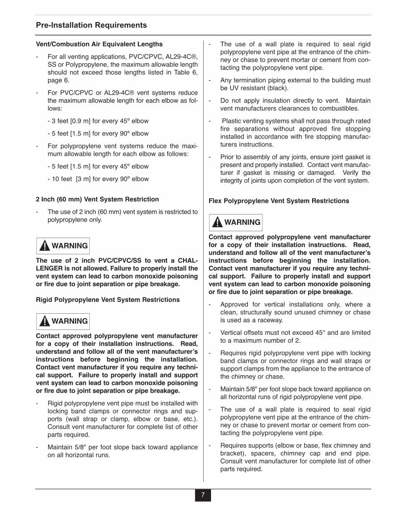
Vent/Combustion Air Equivalent Lengths- For all venting applications, PVC/CPVC, AL29-4C®,
SS or Polypropylene, the maximum allowable lengthshould not exceed those lengths listed in Table 6,page 6.
- For PVC/CPVC or AL29-4C® vent systems reducethe maximum allowable length for each elbow as fol-lows:- 3 feet [0.9 m] for every 45º elbow- 5 feet [1.5 m] for every 90º elbow
- For polypropylene vent systems reduce the maxi-mum allowable length for each elbow as follows:- 5 feet [1.5 m] for every 45º elbow- 10 feet [3 m] for every 90º elbow
2 Inch (60 mm) Vent System Restriction- The use of 2 inch (60 mm) vent system is restricted to
polypropylene only.
The use of 2 inch PVC/CPVC/SS to vent a CHAL-LENGER is not allowed. Failure to properly install thevent system can lead to carbon monoxide poisoningor fire due to joint separation or pipe breakage.
Rigid Polypropylene Vent System Restrictions
Contact approved polypropylene vent manufacturerfor a copy of their installation instructions. Read,understand and follow all of the vent manufacturer’sinstructions before beginning the installation.Contact vent manufacturer if you require any techni-cal support. Failure to properly install and supportvent system can lead to carbon monoxide poisoningor fire due to joint separation or pipe breakage.- Rigid polypropylene vent pipe must be installed with
locking band clamps or connector rings and sup-ports (wall strap or clamp, elbow or base, etc.).Consult vent manufacturer for complete list of otherparts required.
- Maintain 5/8" per foot slope back toward applianceon all horizontal runs.
WARNING
WARNING
- The use of a wall plate is required to seal rigidpolypropylene vent pipe at the entrance of the chim-ney or chase to prevent mortar or cement from con-tacting the polypropylene vent pipe.
- Any termination piping external to the building mustbe UV resistant (black).
- Do not apply insulation directly to vent. Maintainvent manufacturers clearances to combustibles.
- Plastic venting systems shall not pass through ratedfire separations without approved fire stoppinginstalled in accordance with fire stopping manufac-turers instructions.
- Prior to assembly of any joints, ensure joint gasket ispresent and properly installed. Contact vent manufac-turer if gasket is missing or damaged. Verify theintegrity of joints upon completion of the vent system.
Flex Polypropylene Vent System Restrictions
Contact approved polypropylene vent manufacturerfor a copy of their installation instructions. Read,understand and follow all of the vent manufacturer’sinstructions before beginning the installation.Contact vent manufacturer if you require any techni-cal support. Failure to properly install and supportvent system can lead to carbon monoxide poisoningor fire due to joint separation or pipe breakage.- Approved for vertical installations only, where a
clean, structurally sound unused chimney or chaseis used as a raceway.
- Vertical offsets must not exceed 45° and are limitedto a maximum number of 2.
- Requires rigid polypropylene vent pipe with lockingband clamps or connector rings and wall straps orsupport clamps from the appliance to the entrance ofthe chimney or chase.
- Maintain 5/8" per foot slope back toward appliance onall horizontal runs of rigid polypropylene vent pipe.
- The use of a wall plate is required to seal rigidpolypropylene vent pipe at the entrance of the chim-ney or chase to prevent mortar or cement from con-tacting the polypropylene vent pipe.
- Requires supports (elbow or base, flex chimney andbracket), spacers, chimney cap and end pipe.Consult vent manufacturer for complete list of otherparts required.
WARNING

Pre-Installation Requirements
8
- Any termination piping external to the building mustbe UV resistant (black).
- Do not apply insulation directly to vent. Maintainvent manufacturers clearances to combustibles.
- Flex plastic venting systems shall not pass throughrated fire separations.
- Prior to assembly of any joints, ensure joint gasket ispresent and properly installed. Contact vent manufac-turer if gasket is missing or damaged. Verify theintegrity of joints upon completion of the vent system.
Combustion Air Contamination
The combustion air must be piped directly from theoutdoors to the appliance. If the CHALLENGER com-bustion air inlet is located in an area likely to cause orcontain contamination, the combustion air must berepiped and terminated at another location.Contaminated combustion air will damage the appli-ance and its burner system, resulting in possiblesevere personal injury, death or substantial propertydamage.
Do not operate the CHALLENGER if its combustionair inlet is located near a laundry room or pool facil-ity. These areas will always contain hazardous con-taminants.
Pool and laundry products, common household andhobby products often contain fluorine or chlorinecompounds. When these chemicals pass throughthe burner and vent system, they can form strongacids. These acids will corrode the heat exchanger,burner components and vent system, causing seri-ous damage and presenting possible flue gasspillage or water leakage into the surrounding area.
Please read the information listed below. If contam-inating chemicals are located near the area of thecombustion air inlet, the installer should pipe thecombustion air inlet to an outside area free of thesechemicals.
DANGER
WARNING
Potential contaminating products- Spray cans containing chloro/fluorocarbons- Permanent Wave Solutions- Chlorinated wax - Chlorine - based swimming pool chemicals /
cleaners- Calcium Chloride used for thawing ice- Sodium Chloride used for water softening- Refrigerant leaks- Paint or varnish removers- Hydrochloric acid / muriatic acid- Cements and glues- Antistatic fabric softeners used in clothe dryers- Chlorine-type bleaches, detergents, and clean-
ing solvents found in household laundry rooms- Adhesives used to fasten building products and
other similar products
Areas likely to contain these products- Dry cleaning / laundry areas and establishments- Beauty salons- Metal fabrication shops- Swimming pools and health spas- Refrigeration Repair shops- Photo processing plants- Auto body shops- Plastic manufacturing plants- Furniture refinishing areas and establishments- New building construction- Remodeling areas- Garages with workshops
Direct Vent Installation of Vent/Air Piping
9
SECTION II - DIRECT VENT INSTALLATIONOF VENT/AIR PIPING
A Direct Vent appliance utilizes uncontaminated outdoorair (piped directly to the appliance) for combustion.
Direct Vent - Vertical - Through the Roof or UnusedChimney
The installation must conform to the requirements ofthe authority having jurisdiction or, in the absenceof such requirements, to the National Fuel GasCode, ANSI Z223.1/ NFPA 54, and/or Natural Gas andPropane Installation Code, CAN/CSA B149.1.
When using an inoperative chimney as a means of achase for the vent and air, the surrounding spacewithin the chimney cannot be used to draw combus-tion air or vent another appliance.
A gas vent extending through a roof should not ter-minate near an adjacent wall or below any buildingextensions such as roof eaves, balconies or decks.Failure to comply with the required clearances inthis manual could result in severe personal injury,death or substantial property damage.
The information and diagrams outlining the fittingsand method of terminating the vent/combustion airare directly related to PVC/CPVC vent systems.When utilizing and AL29-4C® or Polypropylene ventsystem there may be some variations. Consult theappropriate vent manufacturer for recommenda-tions and clarifications.
NOTICE
WARNING
NOTICE
NOTICE
Determine Termination Location
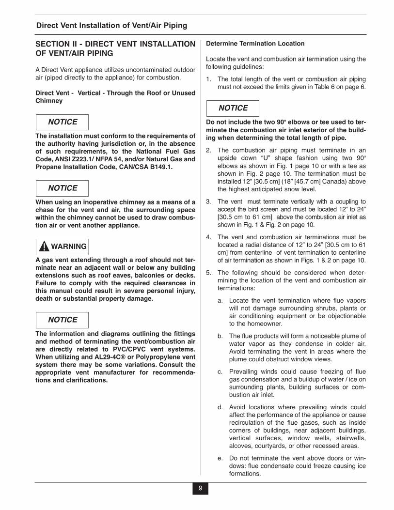
Locate the vent and combustion air termination using thefollowing guidelines:1. The total length of the vent or combustion air piping
must not exceed the limits given in Table 6 on page 6.
Do not include the two 90º elbows or tee used to ter-minate the combustion air inlet exterior of the build-ing when determining the total length of pipe.2. The combustion air piping must terminate in an
upside down “U” shape fashion using two 90ºelbows as shown in Fig. 1 page 10 or with a tee asshown in Fig. 2 page 10. The termination must beinstalled 12” [30.5 cm] (18” [45.7 cm] Canada) abovethe highest anticipated snow level.
3. The vent must terminate vertically with a coupling toaccept the bird screen and must be located 12” to 24”[30.5 cm to 61 cm] above the combustion air inlet asshown in Fig. 1 & Fig. 2 on page 10.
4. The vent and combustion air terminations must belocated a radial distance of 12” to 24” [30.5 cm to 61cm] from centerline of vent termination to centerlineof air termination as shown in Figs. 1 & 2 on page 10.
5. The following should be considered when deter-mining the location of the vent and combustion airterminations:a. Locate the vent termination where flue vapors
will not damage surrounding shrubs, plants orair conditioning equipment or be objectionableto the homeowner.
b. The flue products will form a noticeable plume ofwater vapor as they condense in colder air.Avoid terminating the vent in areas where theplume could obstruct window views.
c. Prevailing winds could cause freezing of fluegas condensation and a buildup of water / ice onsurrounding plants, building surfaces or com-bustion air inlet.
d. Avoid locations where prevailing winds couldaffect the performance of the appliance or causerecirculation of the flue gases, such as insidecorners of buildings, near adjacent buildings,vertical surfaces, window wells, stairwells,alcoves, courtyards, or other recessed areas.
e. Do not terminate the vent above doors or win-dows: flue condensate could freeze causing iceformations.
NOTICE

10
Direct Vent Installation of Vent/Air Piping
12" Min. [30.5 cm]
Radial Distance
12" ([30.5 cm] [18” [ 465.7 cm] Canada)Above the HighestAnticipated Snow Level
Vent Termination
[30.
5 cm
to 6
1 cm
]12
" Min.
- 24
" Max
Abov
e Co
mbu
stion
A
ir In
let
Combustion Air Termination
Direct Vent - Vertical Termination of Vent and Combustion Air Piping.Fig. 1:
Vent Termination
Combustion Air Termination
12" Min. [30.5 cm]
Radial Distance
12" [30.5 cm] [18" [45.7 cm] Canada]
Above the Highest
Anticipated Snow Level
12" M
in. -
24" M
ax[3
0.5
cm -
61 cm
]
Abov
e Co
mbu
stion
A
ir In
let
Fig. 2: Direct Vent - Vertical Termination of Vent and Combustion Air Piping.

f. Locate the vent termination to prevent possiblecondensate damage to exterior finishes.
g. Avoid locations of possible accidental contact offlue vapors with people or pets.
6. The vent termination must also maintain the follow-ing clearances; as shown in Fig.3.a. At least 3 feet [0.9 M] from adjacent wallsb. At least 3 feet [0.9 M] below roof over hangsc. At least 7 feet [2.1 M] above any public walkwaysd. At least 3 feet [0.9 M] above any forced air intake
within 10 feet [3 M] (does not apply to the com-bustion air inlet of a direct vent appliance).
e. No closer than 12” [30.5 cm] below or horizon-tally from any door or window or gravity air inlet.
f. Must be at least 4 feet [1.2 M] from any electricmeters, gas meters-regulators, relief valves orother equipment. Never terminate the ventabove or below any of these items within 4 feet[1.2 M] horizontally.
g. A minimum 12 inches [30.5 cm] horizontal spacingfrom other fan assisted appliance vents such asclothes dryer vent, kitchen exhaust vent etc. Neverterminate the vent above or below any fan assist-ed vent within 12 inches [30.5 cm] horizontally.
7. Locate the vent and combustion air terminations in amanner to protect from damage by foreign objects,such as stones, balls, or buildup of leaves or sediment.
8. Do not connect any other appliance to the vent pipeor multiple appliances to a common vent pipe.
Direct Vent - Vent Installation - Through the Roof1. Vent and Combustion Air Penetration
- Vent pipe penetration through combustible or non-combustible wall material should maintain a mini-mum 1/4” [6 mm] clearance for 3” PVC/CPVCvent. Vent may be installed through a wall thick-ness of up to 20” [50.8 cm] maximum. The diam-eter of the penetration hole should be 4” [10.2 cm]minimum for 3” pipe. When using Polypropyleneor Stainless Steel Vent refer to vent manufacture’sinstallation instructions, supplied with the vent forclearances.
- Combustion air pipe penetration can maintainzero clearance. The diameter of the penetrationhole should be 3-1/2” [8.9 cm] minimum for 3”pipe.
2. The installer must use a galvanized metal thimble forthe vent pipe penetration.
3. Locate the vent and combustion air pipe penetra-tions to provide clearances as described in Fig. 1 &Fig. 2 on page 10.
4. The installer must comply with all local codes for iso-lating the vent and combustion air pipes as theypass through floors, ceilings and roofs.
5. The installer should provide adequate flashing andsealing boots sized for the vent pipe and combustionair pipe.
Termination Fittings - Through the Roof1. The vent and combustion air terminations must include
a factory supplied “bird screen” installed as shown inFigs. 4, 5 & 6 on page 12.
2. The combustion air piping must terminate in anupside down “U” shape fashion using two 90ºelbows as shown in Fig. 1 page 10 or with a tee asshown in Fig. 2 on page 10.
3. The vent piping must terminate vertically with a cou-pling as shown in Figs. 1 & 2 page 10.
Do not extend the vent pipe above the roof beyondthe dimensions shown in Fig. 1 & Fig. 2 on page 10.Extended exposure of the vent pipe could causecondensate to freeze and block the vent pipe.
WARNING
11
Direct Vent Installation of Vent/Air Piping
Termination Clearances of Direct VentSystem
Fig. 3:
[30.5 cm]
[2.1 M]
[3 M]
[0.9 M]
[30.5 cm]

12
Direct Vent Installation of Vent/Air Piping
Vent Termination
Bird Screen*
Fig. 4: Vertical Vent Bird Screen Installation
* Installer must install the factory supplied “birdscreens” on the vent and combustion air terminations.
NOTICE
Combustion Air
Termination
Bird Screen*
Vertical Combustion Air Bird ScreenInstallation with 90º Elbow Termination
Fig. 5:
Combustion AirTermination
Bird Screen*
Vertical Combustion Air Bird ScreenInstallation with Tee Termination
Fig. 6:
13
Direct Vent Installation of Vent/Air Piping
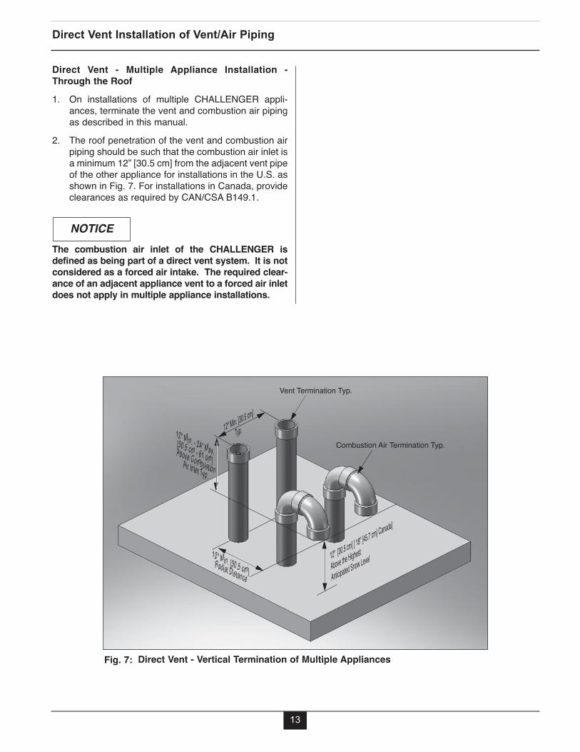
Direct Vent - Multiple Appliance Installation -Through the Roof1. On installations of multiple CHALLENGER appli-
ances, terminate the vent and combustion air pipingas described in this manual.
2. The roof penetration of the vent and combustion airpiping should be such that the combustion air inlet isa minimum 12” [30.5 cm] from the adjacent vent pipeof the other appliance for installations in the U.S. asshown in Fig. 7. For installations in Canada, provideclearances as required by CAN/CSA B149.1.
The combustion air inlet of the CHALLENGER isdefined as being part of a direct vent system. It is notconsidered as a forced air intake. The required clear-ance of an adjacent appliance vent to a forced air inletdoes not apply in multiple appliance installations.
NOTICE
Vent Termination Typ.
Combustion Air Termination Typ.
12" [30.5 cm] [ 18” [45.7 cm] Canada]
Above the Highest
Anticipated Snow Level
12" Min. [30.5 cm]
Typ.
12" Min. [30.5 cm] Radial Distance
12" Min. - 24” Max.[30.5 cm - 61 cm] Above CombustionAir Inlet Typ.
Direct Vent - Vertical Termination of Multiple AppliancesFig. 7:

Direct Vent - Horizontal - Sidewall
The installation must conform to the requirements ofthe authority having jurisdiction or, in the absenceof such requirements, to the National Fuel GasCode, ANSI Z223.1/ NFPA 54, and/or Natural Gas andPropane Installation Code, CAN/CSA B149.1.
For direct vent (sidewall) installations in theCommonwealth of Massachusetts, the installer mustcomply with the additional requirements outlined onpage 26 and 27.
A gas vent extending through a sidewall should notterminate near an adjacent wall or below any build-ing extensions such as roof eaves, balconies ordecks. Failure to comply with the required clear-ances in this manual could result in severe personalinjury, death or substantial property damage.
To reduce the potential of the combustion air inletfreezing up it is recommended to separate the ventand air terminations in both a horizontal and verticalplain as shown in figures 8 and 9 on page 15.
If the vent is terminated on a sidewall which is sub-ject to high winds it is recommended to terminatethe vent using a 45º elbow or tee. A tee provides thebest protection against wind but can expose theexterior of the house to condensate, while a 45ºelbow provides improved protection from both windand condensate.
The information and diagrams outlining the fittingsand method of terminating the vent/combustion airare directly related to PVC/CPVC vent systems.When utilizing and AL29-4C® or Polypropylene ventsystem there may be some variations. Consult theappropriate vent manufacturer for recommenda-tions and clarifications.
WARNING
NOTICE
BEST PRACTICE
BEST PRACTICE
NOTICE
NOTICE
Determine Termination Location
Locate the vent and combustion air termination using thefollowing guidelines:
1. The total length of the vent or combustion air pipingmust not exceed the limits given in Table 6 on page 6.
DO NOT include the 45º or 90º elbows or tee used toterminate the combustion air inlet and vent exteriorof the building when determining the total length ofpipe.2. The combustion air pipe must terminate using a 90º
elbow directed away from the vent termination. Thecombustion air termination must be installed 12” [30.5cm] minimum above grade / highest anticipated snowlevel and as shown in Figs. 8 through 11, page 15.
The combustion air termination can be placed oneither side of the vent termination. The vent andcombustion air terminations must be a minimum 12”[30.5 cm] apart. The vent and combustion air termi-nations are not required to be in the same pressurezone. The combustion air termination must bedirected away from the vent see Figs. 8 through 11,page 15.3. The vent pipe can terminate:- Using a tee as shown in Figs. 8 or 10, page 15.- Using a 45º elbow as shown in Figs. 9 or 11, page 15.The vent termination must be installed 12” [30.5 cm]minimum above grade / highest anticipated snow level.
Do not extend the vent pipe outside the sidewallbeyond the dimensions shown in Figs 8 through 11.Extended exposure of the vent pipe could causecondensate to freeze and block the vent pipe.
WARNING
NOTICE
NOTICE
14
Direct Vent Installation of Vent/Air Piping
15
Direct Vent Installation of Vent/Air Piping
24” [ 61 cm]From Wall To Center-line of Vent12" [30.5 cm]
Min. Above
Grade/Highest
Anticipated
Snow Level
1" [2.5 cm]From Wall To Edge ofCoupling - Air
12" Min.[30.5 cm]
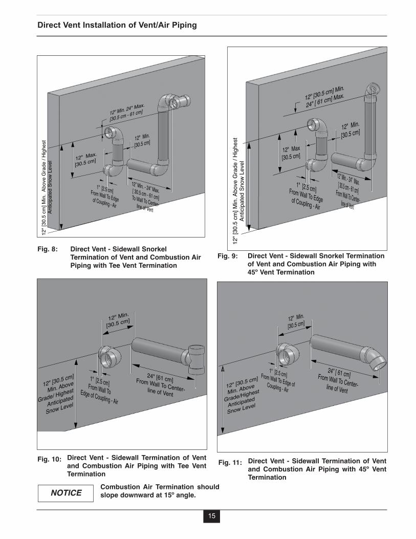
Direct Vent - Sidewall Termination of Ventand Combustion Air Piping with 45º VentTermination
Fig. 11:
24" [61 cm] From Wall To Center-line of Vent12" [30.5 cm]
Min. Above
Grade/ Highest
Anticipated
Snow Level
12" Min.
[30.5 cm]
1" [2.5 cm] From Wall To Edge of Coupling - Air
Direct Vent - Sidewall Termination of Ventand Combustion Air Piping with Tee VentTermination
Fig. 10:
NOTICE
24" [ 61 cm] Max. 12" [30.5 cm] Min.
12” Min. - 24” Max. [ 30.5 cm - 61 cm]From Wall To Center-line of Vent
12" Max[30.5 cm]
12" [
30.5
cm] M
in. A
bove
Gra
de /
High
est
Antic
ipate
d Sn
ow L
evel
1" [2.5 cm] From Wall To Edge of Coupling - Air
12" Min.[30.5 cm]
Direct Vent - Sidewall Snorkel Terminationof Vent and Combustion Air Piping with45º Vent Termination
Fig. 9:
Combustion Air Termination shouldslope downward at 15º angle.
12” Min. - 24” Max. [ 30.5 cm - 61 cm] To Wall To Center-line of Vent
12" [
30.5
cm] M
in. A
bove
Gra
de /
High
est
Ant
icipa
ted
Snow
Lev
el
12" Max.
[30.5 cm]
12" Min.[30.5 cm]
12" Min. 24" Max.
[30.5 cm - 61 cm]
1" [2.5 cm] From Wall To Edge of Coupling - Air
Direct Vent - Sidewall SnorkelTermination of Vent and Combustion AirPiping with Tee Vent Termination
Fig. 8:

4. The combustion air and vent pipe center lines mustbe a minimum of 12” [30.5 cm] apart as shown inFigs. 8 through 11, page 15.
5. The following should be considered when determin-ing the location of the vent and combustion air ter-mination:a. Locate the vent termination where flue vapors
will not damage surrounding shrubs, plants, airconditioning equipment or be objectionable tothe homeowner.
b. The flue products will form a noticeable plumeof water vapor as they condense in colder air.Avoid terminating the vent in areas where theplume could obstruct window views.
c. Prevailing winds could cause freezing of fluegas condensation and a buildup of water / ice onsurrounding plants, building surfaces or com-bustion air inlet.
d. Avoid locations where prevailing winds couldaffect the performance of the appliance or causerecirculation of the flue gases, such as insidecorners of buildings, near adjacent buildings,vertical surfaces, window wells, stairwells,alcoves, courtyards, or other recessed areas.
e. Do not terminate the vent above doors or win-dows: flue condensate could freeze causing iceformations.
f. Locate the vent termination to prevent possiblecondensate damage to exterior finishes.
g. Avoid locations of possible accidental contact offlue vapors with people or pets.
6. The vent termination must also maintain the follow-ing clearances; as shown in Fig.3, page 11.a. At least 3 feet [0.9 M] from adjacent wallsb. At least 3 feet [0.9 M] below roof overhangsc. At least 7 feet [2.1 M] above any public walkwaysd. At least 3 feet [0.9 M] above any forced air intake
within 10 feet [3 M] (does not apply to the com-bustion air inlet of a direct vent appliance).
e. No closer than 12 inches [30.5 cm] below or hor-izontally from any door, window or gravity airinlet.
f. Must be at least 4 feet [1.2 M] from electricmeters, gas meters-regulators, relief valves orother equipment. Never terminate the ventabove or below any of these items or within 4feet [1.2 M] horizontally.
g. A minimum of 12 inches [30.5 cm] or a maximumof 24” [61 cm] beyond the exterior wall whensnorkled, see Figs 8 and 9, page 15 or 24” [61cm] when vent and air terminate on the same hor-izontal plain, see Figs 10 and 11, page 15.
h. A minimum 12 inches [30.5 cm] horizontal spac-ing from other fan assisted appliance vents, seepage 11.
7. The edge of the combustion air termination couplingmust extend 1” [2.5 cm] beyond the exterior wall asshown in Figs 8 through 11, page 15.
8. Locate the vent and combustion air terminations in amanner so as to protect from damage by foreignobjects, such as stones, balls, buildup of leaves orsediment.
9. Do not connect any other appliance to the vent pipeor multiple appliances to a common vent pipe.
16
Direct Vent Installation of Vent/Air Piping

Direct Vent - Vent Installation - Sidewall1. Vent and Combustion Air Penetration
- Vent pipe penetration through combustible ornon-combustible wall material should maintain aminimum 1/4” [6 mm] clearance for 3”PVC/CPVC vent. Vent may be installed througha wall thickness of up to 20” [50.8 cm] maxi-mum. The diameter of the penetration holeshould be 4” minimum [10.2 cm] for 3” pipe.When using Polypropylene or Stainless SteelVent refer to vent manufacture’s installationinstructions, supplied with the vent for clear-ances.
- Combustion air pipe penetration can maintainzero clearance. The diameter of the penetrationhole should be 3-1/2” [8.9 cm] minimum for 3”pipe.
2. The installer must use a galvanized metal thimble forthe vent pipe penetration.
3. Locate the vent and combustion air pipe penetra-tions to provide clearances as described in Figs. 8through 11 page 15.
4. The installer must comply with all local codes for iso-lating the vent pipe as it passes through floors andwalls.
5. The installer should seal all exterior openingsaround penetration with an exterior silicon caulk.
Termination Fittings - Sidewall1. The vent and combustion air terminations must
include a factory supplied “bird screen” installed asshown in Figs. 12 through 14, page 18.
2. The combustion air pipe must terminate using a 90ºelbow as shown in Figs. 8 through 11, page 15.
3. The vent pipe can terminate:- Using a tee as shown in Fig. 8 or 10, page 15.- Using a 45º elbow as shown in Fig. 9 or 11, page 15.
The vent termination must be installed 12” minimum[30.5 cm] above grade / highest anticipated snow level.
Do not extend the vent pipe outside the sidewallbeyond the dimensions shown in Figs. 8 through 11.Extended exposure of the vent pipe could causecondensate to freeze and block the vent pipe.
WARNING
17
Direct Vent Installation of Vent/Air Piping

18
Direct Vent Installation of Vent/Air Piping
Bird Screen*
Vent Termination
Horizontal Vent Bird Screen Installation withTee Termination
Fig. 13:
Combustion AirTermination
Bird Screen*
Horizontal Combustion Air Bird ScreenInstallation with 90º Elbow Termination
Fig. 14:
* Installer must install the factory supplied “birdscreens” on the vent and combustion air inlet termi-nations.
NOTICE
Vent Termination
1
Bird Screen*
Horizontal Vent Bird Screen Installation with45º Elbow Termination
Fig. 12:

19
Direct Vent Installation of Vent/Air Piping
12" M
in. -
24”
Max
[30.
5 cm
- 61
cm]
12" Min.
[30.5 cm]
Horizontally
Between All
Terminations
12" [30.5 cm] Min.
Above Grade/Highest
Anticipated Snow Level
1" [2.5 cm] From Wall To Edgeof Coupling Typ.
12” Min. - 24" Max. [30.5 cm - 61 cm] From Wall To Center-line of Vent Typ.
Direct Vent - Horizontal Termination of MultipleAppliances
Fig. 15:
Direct Vent - Multiple Appliance Installation -Sidewall1. On installations of multiple CHALLENGER appli-
ances, terminate each vent and combustion air pipeas shown in Fig. 15.
2. The wall penetration of the vent and combustion airpipe should be such that the combustion air inlet isa minimum 12” [30.5 cm] from the adjacent vent pipeof the other appliance for installations in the U.S asshown in Fig. 15. For installations in Canada, pro-vide clearances as required by CAN/CSA B149.1.
The combustion air inlet of the CHALLENGER isdefined as being part of a direct vent system. It isnot considered as a forced air intake. The requiredclearance of an adjacent appliance vent to a forcedair inlet does not apply in multiple appliance instal-lations.
NOTICE
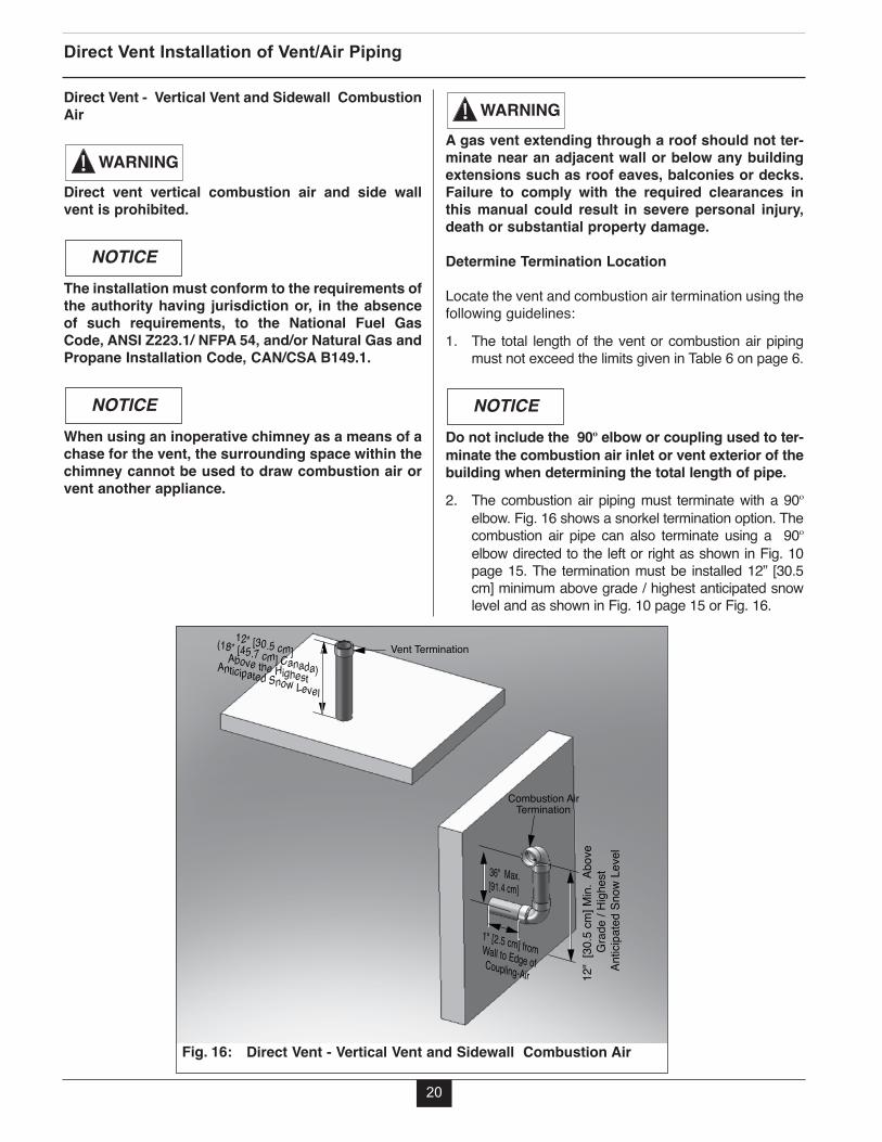
Direct Vent - Vertical Vent and Sidewall CombustionAir
Direct vent vertical combustion air and side wallvent is prohibited.
The installation must conform to the requirements ofthe authority having jurisdiction or, in the absenceof such requirements, to the National Fuel GasCode, ANSI Z223.1/ NFPA 54, and/or Natural Gas andPropane Installation Code, CAN/CSA B149.1.
When using an inoperative chimney as a means of achase for the vent, the surrounding space within thechimney cannot be used to draw combustion air orvent another appliance.
NOTICE
NOTICE
WARNINGA gas vent extending through a roof should not ter-minate near an adjacent wall or below any buildingextensions such as roof eaves, balconies or decks.Failure to comply with the required clearances inthis manual could result in severe personal injury,death or substantial property damage.
Determine Termination Location
Locate the vent and combustion air termination using thefollowing guidelines:1. The total length of the vent or combustion air piping
must not exceed the limits given in Table 6 on page 6.
Do not include the 90º elbow or coupling used to ter-minate the combustion air inlet or vent exterior of thebuilding when determining the total length of pipe.2. The combustion air piping must terminate with a 90º
elbow. Fig. 16 shows a snorkel termination option. Thecombustion air pipe can also terminate using a 90ºelbow directed to the left or right as shown in Fig. 10page 15. The termination must be installed 12” [30.5cm] minimum above grade / highest anticipated snowlevel and as shown in Fig. 10 page 15 or Fig. 16.
NOTICE
WARNING
20
Direct Vent Installation of Vent/Air Piping
1" [2.5 cm] fromWall to Edge ofCoupling-Air
36" Max.[91.4 cm]
12"
[30.
5 cm
] Min.
Abo
ve
Grad
e / H
ighes
t A
ntici
pate
d Sn
ow L
evel
12" [30.5 cm] (18” [45.7 cm] Canada)Above the Highest
Anticipated Snow Level
Combustion Air Termination
Vent Termination
Direct Vent - Vertical Vent and Sidewall Combustion Air Fig. 16:

3. The vent must terminate vertically with a coupling toaccept the bird screen and must be located 12”[30.5 cm] (18” [45.7 cm] Canada) above the highestanticipated snow level.
4. The following should be considered when deter-mining the location of the vent and combustion airtermination:a. Locate the vent termination where flue vapors
will not damage surrounding shrubs, plants orair conditioning equipment or be objectionableto the homeowner.
b. The flue products will form a noticeable plume ofwater vapor as they condense in colder air.Avoid terminating the vent in areas where theplume could obstruct window views.
c. Prevailing winds could cause freezing of fluegas condensation and a buildup of water / ice onsurrounding plants, building surfaces or com-bustion air inlet.
d. Avoid locations where prevailing winds couldaffect the performance of the boiler or causerecirculation of the flue gases, such as insidecorners of buildings, near adjacent buildings,vertical surfaces, window wells, stairwells,alcoves, courtyards, or other recessed areas.
e. Do not terminate the vent above doors or win-dows: flue condensate could freeze causing iceformations.
f. Locate the vent termination to prevent possiblecondensate damage to exterior finishes.
g. Avoid locations of possible accidental contact offlue vapors with people or pets.
5. The vent termination must also maintain the follow-ing clearances; as shown in Fig.3, page 11.a. At least 3 feet [0.9 m] from adjacent wallsb. At least 3 feet [0.9 m] below roof over hangsc. At least 7 feet [2.1 m] above any public walkwaysd. At least 3 feet [0.9 m] above any forced air
intake within 10 feet [3 m] (does not apply to thecombustion air inlet of a direct vent appliance).
e. No closer than 12” [30.5 cm] below or horizon-tally from any door or window or gravity air inlet.
f. Must be at least 4 feet [1.2 m] from any electricmeters, gas meters-regulators, relief valves orother equipment. Never terminate the ventabove or below any of these items within 4 feet[1.2 m] horizontally.
6. The edge of the combustion air termination couplingmust extend 1” [2.5 cm] beyond the exterior wall asshown in Figs. 8 through 11 page 15.
7. Locate the vent termination and combustion air inlet ina manner to protect from damage by foreign objects,such as stones, balls, or buildup of leaves or sediment.
8. Do not connect any other appliance to the vent pipeor multiple boilers to a common vent pipe.
Direct Vent - Vent Installation - Through the Roof1. Vent pipe penetration through combustible or non-
combustible wall material should maintain a mini-mum 1/4” [6 mm] clearance for 3” PVC/CPVC vent.The diameter of the penetration hole should be 4”[10.2 cm] minimum for 3” pipe. When usingPolypropylene or Stainless Steel vent refer to thevent manufacture’s installation instructions, suppliedwith the vent for clearances.
2. The installer must use a galvanized metal thimble forthe vent pipe penetration.
3. The vent must terminate 12” [30.5 cm] (18” [45.7cm] Canada) above the highest anticipated snowlevel.
4. The installer must comply with all local codes for iso-lating the vent pipe as it passes through floors, ceil-ings and roofs.
5. The installer should provide adequate flashing andsealing boots sized for the vent pipe.
Direct Vent - Combustion Air Installation - Sidewall1. Combustion air pipe penetration can maintain zero
clearance. The diameter of the penetration holeshould be 3 1/2” [8.9 cm] minimum for 3” pipe.
2. The combustion air termination must be installed 12”[30.5 cm] minimum above grade / highest anticipat-ed snow level and as shown in Fig. 10 page 15 orFig. 16 page 20.
3. The installer must comply with all local codes for iso-lating the combustion air pipe as it passes throughfloors and walls.
4. The installer should seal all exterior openingsaround penetration with an exterior silicon caulk.
21
Direct Vent Installation of Vent/Air Piping
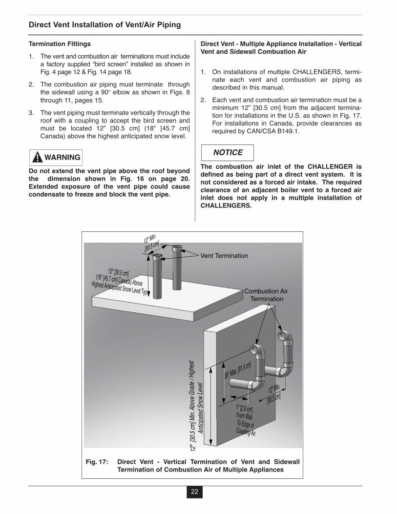
Direct Vent - Multiple Appliance Installation - VerticalVent and Sidewall Combustion Air
1. On installations of multiple CHALLENGERS, termi-nate each vent and combustion air piping asdescribed in this manual.
2. Each vent and combustion air termination must be aminimum 12” [30.5 cm] from the adjacent termina-tion for installations in the U.S. as shown in Fig. 17.For installations in Canada, provide clearances asrequired by CAN/CSA B149.1.
The combustion air inlet of the CHALLENGER isdefined as being part of a direct vent system. It isnot considered as a forced air intake. The requiredclearance of an adjacent boiler vent to a forced airinlet does not apply in a multiple installation ofCHALLENGERS.
NOTICE
Direct Vent Installation of Vent/Air Piping
22
Termination Fittings 1. The vent and combustion air terminations must include
a factory supplied “bird screen” installed as shown inFig. 4 page 12 & Fig. 14 page 18.
2. The combustion air piping must terminate throughthe sidewall using a 90º elbow as shown in Figs. 8through 11, pages 15.
3. The vent piping must terminate vertically through theroof with a coupling to accept the bird screen andmust be located 12” [30.5 cm] (18” [45.7 cm]Canada) above the highest anticipated snow level.
Do not extend the vent pipe above the roof beyondthe dimension shown in Fig. 16 on page 20.Extended exposure of the vent pipe could causecondensate to freeze and block the vent pipe.
WARNING
12" Min.[30.5 cm]
36" Max. [91.4 cm]
12" Min.
[30.5 cm]
12" [3
0.5 cm
] Min.
Above
Grade
/ High
estAn
ticipat
ed Sn
ow Le
vel
12" [30.5 cm] (18” [45.7 cm] Canada) Above Highest Anticipated Snow Level Typ.
1" [2.5 cm]From Wall To Edge ofCoupling-Air
Combustion Air Termination
Vent Termination
Direct Vent - Vertical Termination of Vent and SidewallTermination of Combustion Air of Multiple Appliances
Fig. 17:

SECTION III - INSTALLATION REQUIRE-MENTS
3” to 60 mm Polypropylene Vent Transition and 3”Combustion Air
This section outlines the installation of Venting andCombustion Air for the CHALLENGER when the ventsystem must transition from the 3” outlet of the appli-ance to the 60 mm polypropylene vent system.• The transition from 3” vent system to 60 mm
polypropylene vent system must occur at the appli-ance vent outlet.
• The transition from 3” vent to 60 mm polypropylenevent must occur in a vertical run only.
Transition of 3” vent to 60 mm polypropylene vent ina horizontal run may result in pooling of the con-densate and potential vent blockage. Failure to com-ply can result in death, serious injury or substantialproperty damage.• Use a 3” (80 mm) appliance vent adapter and 3” (80
mm) to 2” (60 mm) reducer to make the transition to60 mm polypropylene vent see Table 2 on page 5.
• The 60 mm polypropylene vent should not transitionback to 3” (80 mm) vent at any point in the vent sys-tem.
• The PVC combustion air piping shall not transitionfrom 3” to 2”.
• The total equivalent length of the 3” (80 mm) ventand 60 mm polypropylene vent combined shall notexceed the length listed for a 60 mm vent in Table 6,page 6.
• The total equivalent length of 3” combustion air pip-ing shall not exceed the length listed for 60 mm ventin Table 6, page 6.
NOTICE
WARNING
Installation Requirements
23
Insert Piping to Appliance Adapters1. The installer must clean, deburr and chamfer the
pipe ends.
The pipe ends must be smooth, free of sharp edgeschamfer and wiped clean to prevent possible dam-age to the sealing gasket in the vent and combustionair adapters. Failure to comply with this require-ment could result in leakage of flue products caus-ing possible severe personal injury or death.
2. Prior to inserting the pipe, inspect the vent and com-bustion air adapters to verify there are no obstruc-tions or packing material inside the adapters and thegaskets are in place.
3. Ensure the adapter banding strap is loose prior toinserting the pipe.
4. Apply a small amount of silicon grease or water tothe insertion end of the pipe to ease insertion intothe adapter.
5. Insert the pipe into the adapter until it is fully seated.
Do not apply excessive force, twist or bend theadapter or vent / combustion air pipe when insert-ing. The adapter gasket could be damaged resultingin possible flue gas leakage.
6. Secure the vent and combustion air pipe by tighten-ing the adapter banding strap. Do not over tightenthe strap. The seal is made with gasket inside theadapter.
WARNING
WARNING

Pipe hangers should not be tightly clamped to pipeto allow for thermal expansion/contraction move-ment. Pipe clamps or hangers should not containany sharp edges which can damage the pipe.8. The vent and combustion air piping should be sloped
continuously from the termination back to the appli-ance with at least 1/4” drop per foot [6 mm/30 cm] ofrun. Do not allow any sags in the run of piping.
Do not pitch the vent or combustion air piping down-ward away from the appliance. Potential conden-sate damage to the building exterior or to the sur-rounding landscape and/or potential risks of icingand blockage of the vent piping could occur.
9. Maintain a minimum clearance of 1/4” [6 mm] betweenthe vent pipe and all materials, combustible or non-com-bustible for 3” PVC/CPVC vent. The installer must sealany wall, floor or ceiling penetrations as per local coderequirements.
It is recommended that the installer uses the samenumber of elbows and length of piping on the vent-ing and the combustion air inlet systems.
Covering PVC/CPVC vent pipe and fittings with ther-mal insulation is prohibited.
Polypropylene or Stainless Steel Vent Systems
When using Polypropylene or Stainless Steel Ventrefer to vent manufacture’s installation instructions,supplied with the vent for proper installation.
Covering Polypropylene vent pipe and fittings withthermal insulation is prohibited.
NOTICE
WARNING
BEST PRACTICE
NOTICE
NOTICE
NOTICE
Installation Requirements
24
PVC/CPVC Vent Systems1. The installer should install the vent / combustion air
piping working from the appliance to the piping termi-nation. The piping should not exceed the lengthsgiven in Table 6 page 6 for either the vent or combus-tion air.
2. The installer should cut the pipe to the requiredlengths and deburr the inside and outside of bothends.
3. The installer should chamfer the outside of the pipeends to allow even distribution of cement when joining.
4. The installer should dry assemble the vent or com-bustion air system prior to assembling any joints toensure proper fit.
5. The pipe ends and fittings should be cleaned anddried thoroughly prior to assembly of the joint.
6. When assembling a joint the installer should:a. Handle fitting and pipes carefully to prevent con-
tamination of surfacesb. Apply a liberal amount of primer to both surfaces
- the end of the pipe and the insert socket of thefitting.
c. Apply a light uniform coating of approvedcement to both surfaces - the end of the pipeand the insert socket of the fitting, while theprimer is still wet.
d. A second coat of approved cement should beapplied to the mating surfaces. The installershould avoid, however, using too much cementon the socket of the fitting to prevent a buildupof cement on the inside.
e. With the cement still wet, the pipe end should beinserted into the socket of the fitting and twisted1/4 of a full turn. Ensure the pipe end is insert-ed fully into the socket of the fitting.
f. Any excess cement should be wiped clean fromthe joint. Inspect the joint to ensure a smoothbead of cement is noticed around the entire jointseam.
7. The installer should use perforated metal strap hang-ers or equivalent pipe hangers suitable for plastic pipeto support the piping. The hangers must be spacedat a maximum of every 5 feet [1.5 M] of horizontaland vertical run of piping. A support must be placedat the appliance and at every change in direction ver-tical or horizontal (i.e elbow). Do not penetrate anypart of the piping or vent system with fastener.

25
SECTION IV - COMMONWEALTH OF MASSACHUSETTS
Installations with the Direct Vent TerminationElevation At or Below 4 feet of Grade:
The following instructions apply to the installation ofa direct vented appliance whose vent terminationand combustion air inlet are installed at or below afour foot elevation (above the grade).
1. If not already present in the structure of the building,a carbon monoxide detector and alarm must beinstalled in the living area outside the bedroom(s).The carbon monoxide detector and alarm is provid-ed by the installer.
The carbon monoxide detector and alarm installed inthe living space outside the bedrooms shall complywith NFPA 720 (2005 edition).
2. A carbon monoxide detector and alarm shall beinstalled in the mechanical room in which the directvent appliance is located. The carbon monoxidedetector and alarm shall:• Be installed on the same 120 volt service circuit
as the appliance such that only one serviceswitch services both the appliance and the car-bon monoxide detector.
• Provide battery back-up power in case of powerfailure
The carbon monoxide detector and alarm installedwithin the same room as the direct vent appliancemust meet ANSI/UL 2034 standards and comply withNFPA 720 (2005 edition). The carbon monoxidedetector and alarm must be tested, approved andlisted with a Nationally Recognized Testing Lab asrecognized under 527 cm.
NOTICE
NOTICE
NOTICE
3. The direct vent termination must be approved for theappliance and when applicable the combustion airinlet must be approved for the appliance.Installation of the vent termination and combustionair inlet shall be in strict compliance with the instal-lation instructions provided with the appliance.
The installer must leave the appliance installationmanual and any documentation regarding the instal-lation of the venting, vent termination and combus-tion air inlet with the appliance upon completion ofthe installation.
4. A metal or plastic identification plate (provided by theinstaller) must be mounted on the exterior wall of thebuilding 4 feet directly above the location of the venttermination and combustion air inlet. The identifica-tion plate shall read “Gas Vent Directly Below”.The size of the plate and lettering shall be of suffi-cient size to be easily read from a distance of 8 feet.
Installations with the Direct Vent TerminationElevation Above 4 feet of Grade:
The following instructions apply to the installation ofa direct vented appliance whose vent terminationand combustion air inlet are installed above a fourfoot elevation above the grade.
NOTICE
NOTICE
Commonwealth of Massachusetts
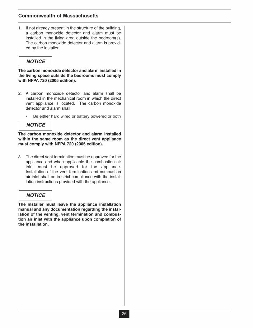
1. If not already present in the structure of the building,a carbon monoxide detector and alarm must beinstalled in the living area outside the bedroom(s).The carbon monoxide detector and alarm is provid-ed by the installer.
The carbon monoxide detector and alarm installed inthe living space outside the bedrooms must complywith NFPA 720 (2005 edition).
2. A carbon monoxide detector and alarm shall beinstalled in the mechanical room in which the directvent appliance is located. The carbon monoxidedetector and alarm shall:• Be either hard wired or battery powered or both
The carbon monoxide detector and alarm installedwithin the same room as the direct vent appliancemust comply with NFPA 720 (2005 edition).
3. The direct vent termination must be approved for theappliance and when applicable the combustion airinlet must be approved for the appliance.Installation of the vent termination and combustionair inlet shall be in strict compliance with the instal-lation instructions provided with the appliance.
The installer must leave the appliance installationmanual and any documentation regarding the instal-lation of the venting, vent termination and combus-tion air inlet with the appliance upon completion ofthe installation.
NOTICE
NOTICE
NOTICE
26
Commonwealth of Massachusetts


Notes:
28

Notes:
29
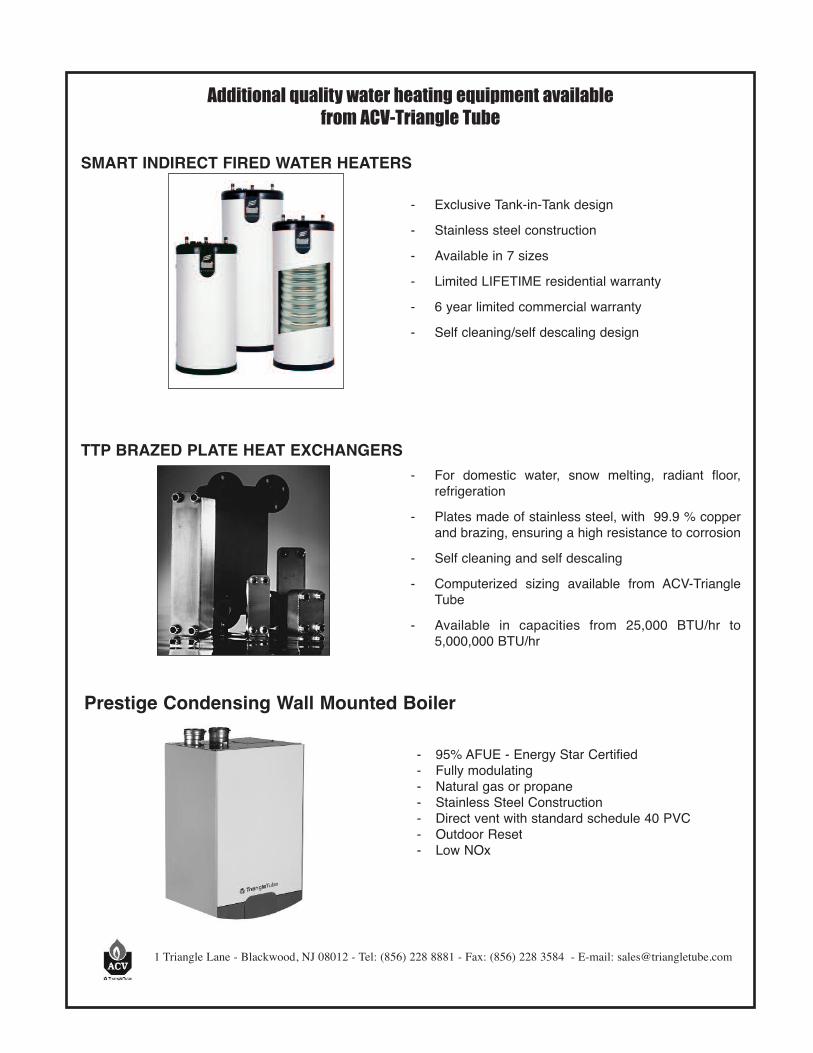
Additional quality water heating equipment available from ACV-Triangle Tube
SMART INDIRECT FIRED WATER HEATERS
TTP BRAZED PLATE HEAT ExCHANGERS
1 Triangle Lane - Blackwood, NJ 08012 - Tel: (856) 228 8881 - Fax: (856) 228 3584 - E-mail: [email protected]
- For domestic water, snow melting, radiant floor,refrigeration
- Plates made of stainless steel, with 99.9 % copperand brazing, ensuring a high resistance to corrosion
- Self cleaning and self descaling- Computerized sizing available from ACV-Triangle
Tube- Available in capacities from 25,000 BTU/hr to
5,000,000 BTU/hr
- Exclusive Tank-in-Tank design- Stainless steel construction- Available in 7 sizes - Limited LIFETIME residential warranty- 6 year limited commercial warranty- Self cleaning/self descaling design
Prestige Condensing Wall Mounted Boiler
- 95% AFUE - Energy Star Certified- Fully modulating- Natural gas or propane- Stainless Steel Construction- Direct vent with standard schedule 40 PVC- Outdoor Reset- Low NOx