PV System Disconnect INSTALLATION & OPERATION MANUAL PV System
36
PV System Discon- 97-600100-06-A02 PV System Disconnect INSTALLATION & OPERATION MANUAL
Transcript of PV System Disconnect INSTALLATION & OPERATION MANUAL PV System

PV System Discon-
97-600100-06-A02
PV System DisconnectINSTALLATION & OPERATION MANUAL

i
PV Powered
PV Powered designs, manufactures, and markets the solar power industry’s most reliable photovoltaic solar inverter solutions. We’ve assembled a highly experienced solar power electronics design team. Our vision is to spur the widespread adoption and success of solar power, by assisting our distributors, dealers and installers in this dynamic market while ensuring that our products are the best supported, easiest to install, and most reliable solar inverters in the industry. Our innovative approach to performance monitoring provides secure and easy access to system performance and inverter status over the Internet.
Contact Information
PV Powered, Inc. PO Box 7348 Bend, OR 97708 Tel: 541-312-3832 Customer Service and Technical Support: 1-877-312-3832 Fax: 541-383-2348 www.pvpowered.com email: [email protected]
Document Copyright
PV System Disconnect Installation and Operation Manual ©2009 PV Powered. All rights reserved. This manual may not be reproduced or distributed without written permission from PV Powered.
Preface
PREFA
CE

ii
Safety Information and Conventions
Designation of Danger, Warning and Caution
!DANGERThe Danger statement is used to inform the installer/operator of a situation requiring the utmost attention. Failure to heed this warning will result in serious injury or death to personnel and destruction of equipment.
!WARNINGThe Warning statement is used to inform the installer/operator of a situation requiring serious attention. Failure to heed this warning may result in serious injury or death to personnel and destruction of equipment.
!CAUTIONThe Caution statement is used to inform the installer/operator of a situation requiring attention. Failure to heed this Caution may result in injury to personnel and damage to equipment.
Revisions and Certification
For applicability of technical information with your specific product, contact PV Powered Customer Service and Technical Support at [email protected].

iii
PV System DisconnectInstallation and Operation Manual
Acronyms and Abbreviations
AC Alternating Current
ANSI American National Standards Institute
AWG American Wire Gage
CEC California Energy Commission
CPU Controlled Processing Unit
DC Direct Current
EGC Equipment Grounding Conductor
FCC Federal Communications Commission (US)
GEC Grounding Electrode Conductor
GFI Ground Fault Interrupt
LED Light-Emitting Diode
LOTO Lockout Tagout
LP Low Power
MPPT Maximum Power Point Tracking
NEMA National Electrical Manufacturers Association
NEC National Electric Code
NFPA National Fire Protection Association
PV Photovoltaic
STC Standard Test Condition
UL Underwriters Laboratory
VAC Voltage Alternating Current
VDC Voltage Direct Current
VFD Vacuum Fluorescent Display
VOC Voltage Open Circuit
VOC_TC Voltage Open Circuit, Temperature Coefficient

iv
Table of Contents
Table of ContentsPreface ..................................................................................................................................iSafety Information and Conventions .................................................................................. iiAcronyms and Abbreviations ............................................................................................. iii1. Installation and Safety ....................................................................................................1
1.1 Installing the PV System Disconnect ........................................................................11.2 General Safety ...........................................................................................................1
2. Wiring .............................................................................................................................32.1 Wiring Requirements .................................................................................................32.2 Wiring Information ....................................................................................................32.3 AC Circuit Breaker Requirements .............................................................................4
3. Disconnect Requirements ...............................................................................................53.1 Single-point Grounding .............................................................................................53.2 Electrical Connections ...............................................................................................8
4. Wiring the Disconnect ..................................................................................................104.1 Accessing the PV System Disconnect’s Wiring Terminals ......................................104.2 Wiring the PV System Disconnect to External Connections ...................................104.3 Wiring Multiple PV System Disconnects ................................................................12
5. Service and Replacement ..............................................................................................155.1 Accessing the Wiring Terminals ..............................................................................155.2 Removing the Inverter .............................................................................................165.3 Replacing the Inverter .............................................................................................165.4 Wiring the Replaced Inverter to the PV System Disconnect ...................................175.5 Finishing the Replacement ......................................................................................18
Appendix A - Specifications ..............................................................................................19Appendix B - Dimensions ..................................................................................................21
B.1 Schematics for PVP1100W, PVP2000W, PVP2500W, PVP2800W, PVP3000W, and PVP3500W Inverter Cabinet ...........................................21
B.2 Schematics for PVP4600W, PVP4800W, and PVP5200W Inverter Cabinet .........22Limited Warranty ...............................................................................................................24Return Procedure ...............................................................................................................27Index ..................................................................................................................................28
TAB
LE O
F C
ON
TEN
TS

v
List of Figures & TablesFigure 3-1 Grounding of the Inverter and PV System Disconnect ..................................6Table 3-1 Grounding Electrode Conductor Size .............................................................6Figure 3-2 System Block Diagram of Single-point System Ground ...............................7Table 3-2 Required Branch Circuit Protection ...............................................................8
Figure 4-1 PV System Disconnect’s Wiring Terminal Locations ..................................10Table 4-1 PV Open Circuit Voltages .............................................................................11Figure 4-2 Connections for the PV System Disconnect’s AC Conductors:
EGC, Line 1 and Line 2/N ..........................................................................12
Figure 5-1 Connections between the Inverter and PV System Disconnect ...................16Figure 5-2 Reconnecting the Inverter’s Conductors ......................................................17
Table A-1 PV System Disconnect Technical Specifications ..........................................19Table A-2 Torque Values ................................................................................................19Table A-3 Circuit Breaker Requirements ......................................................................19
Figure B-1 Side and Front Views of PVP1100W, PVP2000W, PVP2500W, PVP2800W, PVP3000W, and PVP3500W Inverter Cabinet ......................20
Figure B-2 Back and Bottom Views of PVP1100W, PVP2000W, PVP2500W, PVP2800W, PVP3000W, and PVP3500W Inverter Cabinet ......................21
Figure B-3 Side and Front Views of the PVP4600W, PVP4800W, and PVP5200W Inverter Cabinet ................................................................22
Figure B-4 Back and Bottom Views of the PVP4600W, PVP4800W, and PVP5200W Inverter Cabinet ................................................................23

1
The PV System Disconnect is a separate but necessary and integrated part of the PV Powered Grid-tied Residential Inverter installation. The PV System Disconnect is designed for use with the PVP1100W, PVP2000W, PVP2500W, PVP2800W, PVP3000W, PVP3500W, PVP4600W, PVP4800W and PVP5200W inverters.
The PV System Disconnect is tied to both electrical sources, the utility grid and the PV system array for each inverter. The PV System Disconnect provides the disconnect for DC and AC connections.
This manual provides information necessary for the safe installation and operation of the PV System Disconnect.
Installing the PV System Disconnect1.1
The inverter and the PV System Disconnect ship as an integrated unit. When the inverter installation is complete, the PV System Disconnect also needs to be secured to the wall.
Make sure the AC/DC ON/OFF switch is in the OFF position. 1. Remove the screws around the edge of the PV System Disconnect’s front cover and 2. remove the lid.Secure the PV System Disconnect to the wall at the two internal locations using a rubber 3. washer with a #13 zinc or stainless steel screw. The rubber washer seals the hole. The screws must secure to a single stud for rigidity. Refer to the wall mount template for specific locations.
The PV System Disconnect remains in place when the inverter is removed for service.
General Safety1.2
IMPORTANT SAFETY INSTRUCTIONS: This product has been engineered and manufactured to ensure your personal safety. Improper installation and operation may result in potential electrical shock or burns. Read and follow all instructions for installation, use and servicing of this product. Read all safety warnings before installing or operating the inverter and disconnect.
The PV System Disconnect has a locking on/off switch. When the switch is in the off position, a lock can be inserted through the switch so it cannot be opened. It is the responsibility of the end user to provide the lock.
SAVE THESE INSTRUCTIONS: This manual contains important instructions for the PV System Disconnect that must be followed during installation and maintenance.
INSTRUCTIONS IMPORTANTES CONCERNANT LA SECURITÉ CONSERVER CES INSTRUCTIONS. CETTE NOTICE CONTIENT DES INSTRUCTIONS IMPORTANTES CONCERNANT LA SÉCURITÉ.
1. Installation and Safety
INSTA
LLATIO
N&
SA
FETY

2
!CAUTION All electrical installations should be done in accordance with local electrical codes and the National Electrical Code (NEC), ANSI/NFPA 70.
Only qualified electricians should make the connection between the PV System Disconnect and the utility grid.
When exposed to light, photovoltaic (PV) arrays create electrical energy that cause a hazardous condition. To avoid this, completely cover the surface of all PV arrays with opaque (dark) material before wiring them.
The PV System Disconnect contains no user-serviceable parts. Refer maintenance to qualified service personnel.

3
Wiring Requirements2.1
The design intent of the inverter and PV System Disconnect assembly is to provide a safe method of connecting the inverter from the PV system array and the utility service source circuits. The PV System Disconnect provides a single location for terminating AC, DC and ground conductors.
In addition, the PV System Disconnect provides the following:
An AC/DC ON/OFF disconnect switch to the PV array and the utility service, • and functions as a wire raceway.Is shipped with the inverter as an integrated assembly, housed individually: an • inverter and a disconnect.Allows an inverter to be removed for service• while leaving the PV System Disconnect in place.
!CAUTION All electrical installations should be done in accordance with local electrical codes and the National Electrical Code (NEC), ANSI/NFPA 70.
Only qualified electricians should make the connection between the PV System Disconnect and the utility grid.
When exposed to light, photovoltaic (PV) arrays create electrical energy that cause a hazardous condition. To avoid this, completely cover the surface of all PV arrays with opaque (dark) material before wiring them.
The PV System Disconnect contains no user-serviceable parts. Refer maintenance to qualified service personnel.
Wiring Information2.2
Wire raceway
The wire raceway is the cavity in the bottom of the PV System Disconnect cabinet. The wire raceway is designed to accommodate the wiring of multiple inverters with PV System Disconnects. Additional knockouts on each PV System Disconnect cabinet provides access for running the AC and DC source circuits and system grounding conductors through the raceway. There is room for expanding the knockouts if it is required.
2. Wiring
WIR
ING

4
Conductor size and stripping length
Use a conductor size as specified by NEC. Strip all conductors 9 mm (3/8 inch) and torque to a maximum 1.8Nm (16 in-lbs). Use copper conductors only, rated at 90° C.
AC Circuit Breaker Requirements2.3
The main utility service panel must dedicate a single- or multi-pole breaker to operate each installed 120/240/208 VAC PV Powered Inverter. This circuit breaker must be sized to handle the rated maximum output voltage and current of the PV Powered Inverter and PV System Disconnect. Refer to the Circuit Breaker Requirements in Appendix A.
An exception exists if a dedicated PV system AC sub-panel is used to combine multiple inverters. The dedicated PV system AC sub-panel requires a single breaker at the main utility service panel for a multiple inverter installation.

5
The PV System Disconnect is a PV array and utility grid disconnect switch that connects or disconnects both AC and DC source circuits using a single switch.
!WARNING: Shock hazardDo not remove the PV System Disconnect after is installed.
The AC/DC disconnect switch in the PV System Disconnect is compliant with UL 98. This is a non-serviceable component and needs to remain in place even during removal of the inverter. Removal of the PV System Disconnect can expose energized conductors.
Use caution when working around DC source circuits. Although the AC/DC disconnect switch disconnects the inverter from both AC and DC source circuits, hazardous voltages may still be present on the source side of the switch and inside the PV System Disconnect housing.
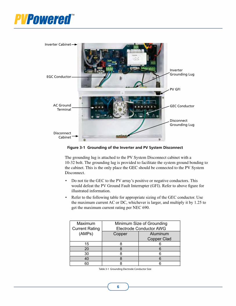
Single-point Grounding3.1
The PV System Disconnect uses a single-point grounding connection, the grounding lug, providing continuity for both the Equipment Grounding Conductor (EGC) and Grounding Electrode Conductor (GEC).
The grounding lug is permanently bonded to the metal of the PV System Disconnect. The inverter and the PV System Disconnect are connected by copper conductors and do not rely on conduit connections for bonding. All ground connections between the inverter cabinet and the PV System Disconnect cabinet are completed at the factory. During installation you will complete the ground connections by:
Connecting the GEC coming from the PV system array, and• Connecting the EGC coming from the main utility service panel.•
The following figure shows the pre-existing ground connections between the inverter and disconnect cabinets and the location of the ground connections that need to be completed. For information on connecting or disconnecting the single-point ground when replacing the inverter, see Connecting the Ground Conductors of Multiple Disconnects in the next chapter.
3. Disconnect Requirements
DIS
CO
NN
EC
TR
EQ
UIR
EM
EN
TS
6
Figure 3-1 Grounding of the Inverter and PV System Disconnect
The grounding lug is attached to the PV System Disconnect cabinet with a 10-32 bolt. The grounding lug is provided to facilitate the system ground bonding to the cabinet. This is the only place the GEC should be connected to the PV System Disconnect.
Do not tie the GEC to the PV array’s positive or negative conductors. This • would defeat the PV Ground Fault Interrupter (GFI). Refer to above figure for illustrated information. Refer to the following table for appropriate sizing of the GEC• conductor. Use the maximum current AC or DC, whichever is larger, and multiply it by 1.25 to get the maximum current rating per NEC 690.
Maximum Current Rating
(AMPs)
Minimum Size of Grounding Electrode Conductor AWG
Copper Aluminum Copper Clad
15 8 620 8 630 8 640 8 660 8 6
Table 3-1 Grounding Electrode Conductor Size
Inverter Cabinet
Disconnect Cabinet
Disconnect Grounding Lug
Inverter Grounding Lug
PV GFI
GEC Conductor
EGC Conductor
AC Ground Terminal

7
PV System DisconnectInstallation and Operation Manual
The following figure is a schematic representation of the PV Powered single-point grounding. The front lid is grounded through the metal pem insert which accepts each screw securing the lid.
Residential Inverter Function Architecture
+
PV SystemGround
PV NEG PV POSL1 L2
Power PCB
Control PCB
LineFilter
+++++
AC/DCDisconnect
PVM1010
DCPower Supply
DSP
DC Disconnect Board
+ + + GND - - -
AC Disconnect Board
Gnd L1 L2
GND
GFI Detect
Figure 3-2 System Block Diagram of Single-point System Ground
For information about grounding multiple inverters and PV System Disconnects, see Connecting the Ground Conductors of Multiple Units.

8
Electrical Connections3.2
!CAUTIONThe National Electrical Code (NEC) requires that the inverter and the PV System Disconnect be connected to a dedicated circuit with no other outlets or devices connected to the same circuit. See NEC Section 690-64(b)(1). The NEC places limitations on the size of the inverter and the manner in which the PV System Disconnect is connected to the utility grid. See NEC Section 690-64(b)(2).
To reduce the risk of fire, connect the inverter and the PV System Disconnect to the appropriate size circuit breaker provided in the following table. Maximum branch-circuit over-current protection is calculated in accordance with the National Electrical Code (NEC), ANSI/NFPA 70.
Circuit Breaker Requirements
Inverter Model Circuit Breaker Required
PVP1100W 1 pole 15APVP2000W 2 pole 15APVP2500W 2 pole 20APVP2800W 2 pole 20APVP3000W 2 pole 20APVP3500W 2 pole 20APVP4600W 2 pole 30APVP4800W 2 pole 30APVP5200W 2 pole 30A
Table 3-2 Required Branch Circuit Protection
!WARNINGElectrical connections must be completed in accordance with local electrical codes and the National Electrical Code (NEC), ANSI/NFPA 70. Use 12 AWG, minimum, 90oC copper wire for all inverter electrical connections. Voltage drop as well as other considerations may dictate using larger conductor sizes.
!WARNING
Ensure the main circuit breaker in the utility service panel is switched OFF before wiring the inverter and the PV System Disconnect. This circuit breaker should be switched ON only after all wiring has been completed as described in this manual.
9
PV System DisconnectInstallation and Operation Manual
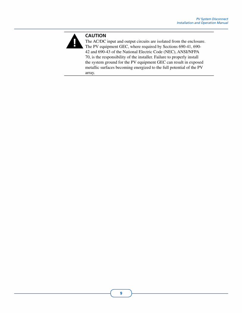
!CAUTIONThe AC/DC input and output circuits are isolated from the enclosure. The PV equipment GEC, where required by Sections 690-41, 690-42 and 690-43 of the National Electric Code (NEC), ANSI/NFPA 70, is the responsibility of the installer. Failure to properly install the system ground for the PV equipment GEC can result in exposed metallic surfaces becoming energized to the full potential of the PV array.

10
Accessing the PV System Disconnect’s Wiring Terminals4.1
To access the disconnect’s wiring terminals:
Make sure the AC/DC ON/OFF switch is in the OFF position.1. Remove the screws around the edge of the PV System Disconnect’s front cover 2. and remove the lid.
Now the disconnect’s wiring terminals are accessible. Refer to the following figure to review the terminal locations.
Figure 4-1 PV System Disconnect’s Wiring Terminal Locations
Wiring the PV System Disconnect to External Connections4.2
Connecting to the PV System Array
The DC input terminals provided in the disconnect accept up to 6 AWG multi-stranded conductors from the PV system array.
Calculate the maximum open circuit voltage (VOC) for each series of modules 1. based on NEC 690-7.
NOTE: For all temperature conditions, the VOC for each series connection must total less than the 500 VDC for all residential inverter models.
4. Wiring the Disconnect
AC Wiring Connections
Grounding Lug
DC Wiring Connections
WIR
ING
TH
E D
ISC
ON
NEC
T

11
InverterModel
Maximum In-verter
Start Voltage
Absolute Maxi-mum
Input VoltagePVP1100W 450VDC 500VDCPVP2000W 450VDC 500VDCPVP2500W 450VDC 500VDCPVP2800W 450VDC 500VDCPVP3000W 450VDC 500VDCPVP3500W 450VDC 500VDCPVP4600W 450VDC 500VDCPVP4800W 450VDC 500VDCPVP5200W 450VDC 500VDC
Table 4-1 PV Open Circuit Voltages
Clearly label the positive, negative and ground conductors coming from the PV 2. system array.Select a knockout to route the conductors into the disconnect and insert a water-3. tight fitting.Route the PV system array’s conductors through the fitting. Make sure the posi-4. tive is connected to the positive, negative to negative, and the GEC is terminated at the grounding lug.
Connecting to the Utility Grid
The PV System Disconnect is connected to the main utility service panel using three conductors: Line 1, Line 2/N and EGC.
NOTE: To avoid an increase in AC voltage level, which may lead to nuisance faults, PV Powered recommends sizing the conductor for a drop of less than 2%.
!WARNINGEnsure the main circuit breaker at the utility service panel is switched off before connecting to the AC terminal block.
Run the AC conductor from the main utility service panel to the PV System 1. Disconnect using an NEC compliant method.Insert a water-tight fitting into the PV System Disconnect’s knockout and secure 2. the fitting with a locking nut.Feed the Line 1, Line 2/N and 3. EGC conductors through the conduit and into the selected knockout of the PV System Disconnect. Connect the EGC conductor to the terminal displaying the symbol 4. inside the disconnect. Connect the Line 2/N conductor to the terminal marked “L2” inside the discon-5. nect. (For the PVP1100W this is the neutral conductor.)Connect the Line 1 conductor to the terminal marked “L1” inside the disconnect. 6.

12
PV System DisconnectInstallation and Operation Manual
Ensure all connections are wired correctly and properly torqued. Tighten the 7. terminal block screws to 24 in-lbs.
Figure 4-2 Connections for the PV System Disconnect’s AC Conductors: EGC, Line 1 and Line 2/N
This completes the wiring for the inverter and PV System Disconnect to the PV system array and the electric utility.
Closing the PV System Disconnect
Replace the PV System Disconnect’s lid and tighten the four screws.1.
!WARNINGBefore turning on the inverter and PV System Disconnect, ensure that the front panel is closed properly and the lid’s screws are tightened.
To start the inverter with the PV System Disconnect, see the PV Powered Grid-2. Tied Inverter manual’s Operations chapter.
Wiring Multiple PV System Disconnects4.3
If there is more than one PV system array, make sure the positive, negative and ground conductors are labeled for each array. For example:
PV array 1 = PV1 pos, PV1 neg, PV1 ground• PV array 2 = PV2 pos, PV2 neg, PV2 ground• PV array 3 = PV3 pos, etc.•
The AC and DC wiring connections are the same for multiple and single inverter/disconnect installation. The system grounding requirements vary slightly from a single inverter to a multiple inverter installation with PV System Disconnects. The DC GEC must maintain continuity through all pieces of equipment, and careful attention must be paid to avoid ground loops.
EGC
Line 1
Line 2/N

13
Preparing for Wiring Multiple PV System Disconnects
The wiring raceway allows a continuous run of the AC, DC and system ground conductors between multiple inverter and PV System Disconnect units.
Make sure each PV System Disconnect AC/DC ON/OFF switch is in the OFF 1. position. Remove the screws from the lid of each PV System Disconnect.2. Remove the knockouts on each PV System Disconnect to access the wiring 3. raceway.Insert a fitting in each knockout opening so a continuous, 4. water-tight connection is created between each PV System Disconnect. Route the AC, DC and the system ground conductors through each PV System 5. Disconnect, terminating applicable connections.
For instructions on connecting the PV array and the AC conductors inside the PV System Disconnect, refer to the section Wiring the PV System Disconnect to External Connections.
Connecting the Ground Conductors of Multiple Units
System grounding requirements for a multiple unit system also uses a single-point ground.
Connect the GEC coming from the first PV array to the grounding lug inside the 1. disconnect cabinet of the first unit.Connect the remaining units with a continuous GEC, branching from grounding 2. lug to grounding lug.On each unit, connect the EGC from the utility grid to the grounding terminal of 3. the AC connection.

14
PV System DisconnectInstallation and Operation Manual
GND L1 L2/N Pos Gnd NegPos Gnd Neg
Inverter #2Inverter #1 Inverter #3
GND L1 L2/N GND L1 L2/NPos Gnd Neg Pos Gnd Neg
Figure 4-3 Wiring Multiple Arrays with Inverter/PV System Disconnects
To start the inverter with the PV System Disconnect, see the PV Powered Grid-Tied Residential Inverters manual’s Operations chapter.
From UtilityL1, L2/N and EGC
From PV SystemPos, Neg and GEC

15
PV Powered provides service guidelines for disconnecting and replacing an inverter. Always request and receive an advanced replacement prior to separating the inverter from the PV System Disconnect assembly. PV Powered maintains an advanced replacement policy which provides qualified personnel with a similar inverter for immediate replacement of the unit being removed.
In the unlikely event the inverter requires replacement, the PV System Disconnect remains in place. Only the inverter is removed and immediately replaced.
Note: If the inverter cannot be replaced immediately, it is the qualified service personnel’s responsibility to provide ¾” water-tight plugs as specified by UL 514B. These plugs need to be installed in the disconnect’s knockouts to protect the inside of the AC/DC disconnect assembly from exposure to the elements.
Accessing the Wiring Terminals5.1
On the PV System Disconnect, move the AC/DC handle to the OFF position.1.
Note: The AC/DC disconnect switch must be in the off position before the lid can be removed.
Note: The load side terminals of the AC and DC source circuits may still be energized.
Note: Wait five minutes before proceeding, allowing the inverter’s capacitors to discharge.
Remove the screws located around the front perimeter of the inverter and re-2. move the lid.Remove the screws around the front edge of the PV System Disconnect and 3. remove the lid.
Now the wiring terminals in the inverter and PV System Disconnect are accessible. Review the following figure for terminal locations.
5. Service and Replacement
SER
VIC
E &
REPLA
CEM
EN
T

16
Figure 5-1 Connections between the Inverter and PV System Disconnect
Removing the Inverter5.2
Disconnect the AC and DC conductors, including the GEC1. at the grounding lug, inside the inverter.Pull all conductors down through the appropriate fitting to the wiring raceway 2. inside the PV System Disconnect.Remove the locking nuts on the conduit fittings between the inverter and the 3. disconnect.Remove the three mounting screws in the lower section of the inverter assembly 4. to detach the inverter from the mounting bracket.Lift the inverter from the mounting bracket.5. Replace the lid on the inverter.6.
Replacing the Inverter5.3
Remove the screws and the lid on the replacement inverter.1. Place the replacement inverter on the mounting bracket.2. Replace the three mounting screws in the lower section of the inverter assembly 3. to secure the inverter to the mounting bracket.Reinstall each of the fittings with their locking nuts in the knockouts for the 4. conductors.
AC Conductor Connections
Inverter Cabinet
Disconnect Cabinet
AC Conductor Connections
Wiring Raceway}
Locking Nuts on Fittings
DC Conductor Connections
DC Conductor Connections
Locking Nuts on Fittings
Mounting Screws
Grounding Lug

17
PV System DisconnectInstallation and Operation Manual
Wiring the Replaced Inverter to the PV System Disconnect5.4
The PV System Disconnect connections are arranged in the following configuration:
The left side is dedicated to AC.• The right side is dedicated to DC. •
DC Connections
To wire the DC conductors from the PV System Disconnect to the replaced inverter:
Route the DC conductors through the correct fitting and into the inverter.1. Connect the DC conductors to the DC wiring terminals inside the inverter. 2.
Connect positive to positive.• Connect negative to negative.• GEC is terminated at the grounding lug.•
AC Connections
To wire the AC connections from the PV System Disconnect to the replaced inverter:
Route the AC conductors through the correct fitting and into the inverter. 1. Connect the EGC conductor to the GND terminal. 2. Connect the conductor coming from “L2” in the disconnect to the terminal 3. marked “Line 2/N” inside the inverter. (For the PVP1100W this is the neutral conductor.)Connect the conductor coming from “L1” to the terminal marked “Line 1” inside 4. the inverter. Ensure all connections are wired correctly and properly torqued. Tighten the 5. terminal block screws to 24 in-lbs.
Figure 5-2 Reconnecting the Inverter’s Conductors
AC Conductor Connections
Inverter Cabinet
Disconnect Cabinet
DC Conductor Connections
Grounding Lug
}
AC Conductors, from Disconnect, Threaded
through FittingDC Conductors, from Disconnect, Threaded through Fitting
Line 1 Line 2/N GND
+-GEC

18
Finishing the Replacement5.5
Replace the lids and the screws securing the lids for the inverter and the PV 1. System Disconnect.
To start the inverter with the PV System Disconnect, see the PV Powered Grid-Tied Inverter manual’s Operations chapter.
19
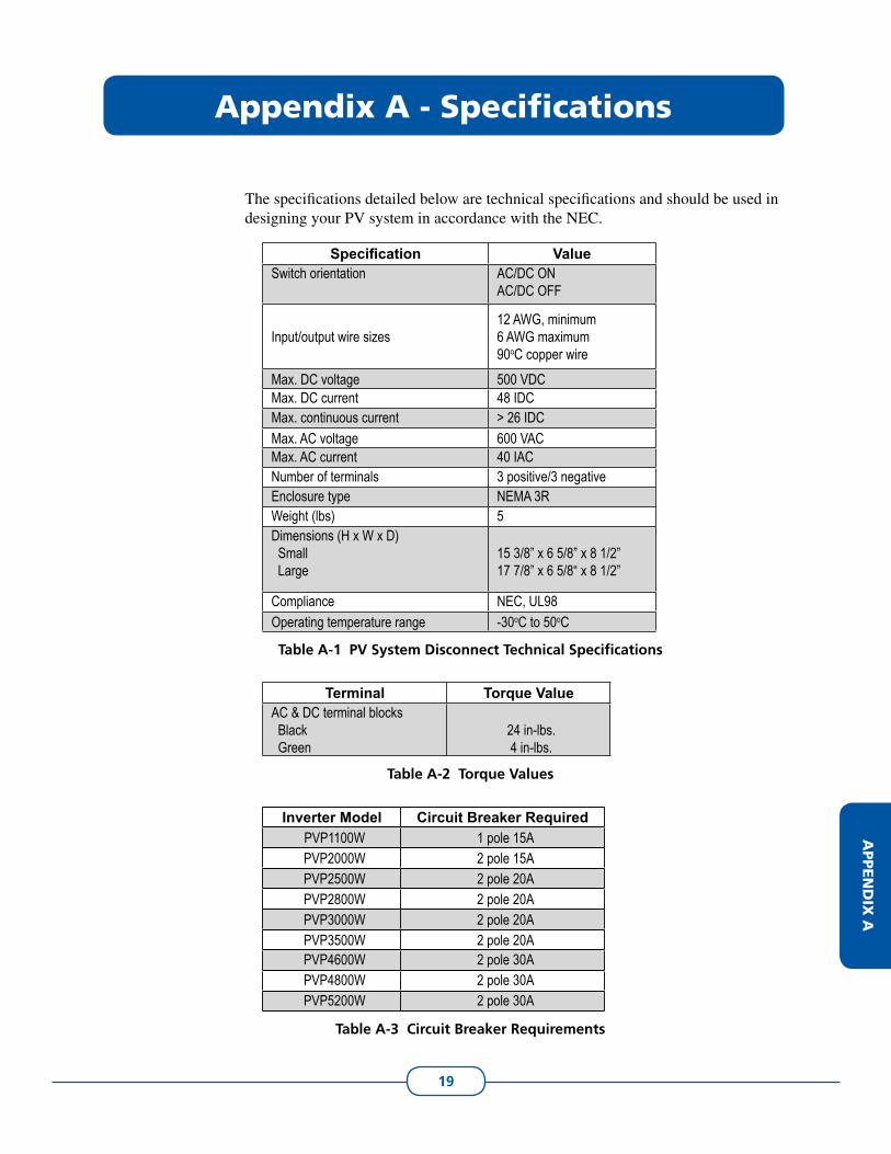
The specifications detailed below are technical specifications and should be used in designing your PV system in accordance with the NEC.
Specification ValueSwitch orientation AC/DC ON
AC/DC OFF
Input/output wire sizes12 AWG, minimum 6 AWG maximum 90oC copper wire
Max. DC voltage 500 VDCMax. DC current 48 IDCMax. continuous current > 26 IDCMax. AC voltage 600 VACMax. AC current 40 IACNumber of terminals 3 positive/3 negativeEnclosure type NEMA 3RWeight (lbs) 5Dimensions (H x W x D) Small Large
15 3/8” x 6 5/8” x 8 1/2”17 7/8” x 6 5/8“ x 8 1/2”
Compliance NEC, UL98Operating temperature range -30oC to 50oC
Table A-1 PV System Disconnect Technical Specifications
Terminal Torque ValueAC & DC terminal blocks Black Green
24 in-lbs.4 in-lbs.
Table A-2 Torque Values
Inverter Model Circuit Breaker RequiredPVP1100W 1 pole 15APVP2000W 2 pole 15APVP2500W 2 pole 20APVP2800W 2 pole 20APVP3000W 2 pole 20APVP3500W 2 pole 20APVP4600W 2 pole 30APVP4800W 2 pole 30APVP5200W 2 pole 30A
Table A-3 Circuit Breaker Requirements
Appendix A - Specifications
APPEN
DIX
A

20
15 5/8"
30 3/8"
LED STATUS INDICATORS
VFD DISPLAY
3"
1" 7 1/4"
10"
1 1/8"
1"3/4", 1" K.O.
1/2", 3/4" K.O.
LEFT VIEWFRONT VIEW
Figure B-1 Side and Front Views of PVP1100W, PVP2000W, PVP2500W, PVP2800W, PVP3000W, and PVP3500W Inverter Cabinet

21
Schematics for B.1 PVP1100W, PVP2000W, PVP2500W, PVP2800W, PVP3000W, and PVP3500W Inverter Cabinet
7"
3 3/4"
7 1/2"11 1/4"
3 5/8"
16 1/2"
21 7/8"
1"
1 5/8"
1"
1 7/8"
10"
BACK VIEW
7/8"1"
3"
4 3/8"
6 1/2"
3 1/8"
4 1/2"
1/2", 3/4" K.O.
1/2" K.O.
DRAINAGE PORT
BOTTOM VIEW
Figure B-2 Back and Bottom Views of PVP1100W, PVP2000W, PVP2500W, PVP2800W, PVP3000W, and PVP3500W Inverter Cabinet
Appendix B - Dimensions
APPEN
DIX
B

22
Schematics for B.2 PVP4600W, PVP4800W, and PVP5200W Inverter Cabinet
Figure B-3 Side and Front Views of the PVP4600W, PVP4800W, and PVP5200W Inverter Cabinet
18 1/8"
35"
LED STATUS INDICATORS
VFD DISPLAY7 5/8"1"
3"
1 1/8"
1 1/8"
9"
3/4",1" K.O.
1/2", 3/4" K.O.
LEFT VIEW
FRONT VIEW

23
PV System DisconnectInstallation and Operation Manual
Figure B-4 Back and Bottom Views of the PVP4600W, PVP4800W, and PVP5200W Inverter Cabinet
4 1/4"4 1/4"
5 1/4"
5"
10"
15"
22 3/4"
16"
1 5/8"1"
1 7/8"
3 5/8"
16"CL
BACK VIEW
3"
4 3/8"
7 3/4"
3 1/8"
4 1/2"
7/8" 1"
1/2" K.O.
1/2",3/4" K.O.
DRAINAGE PORT
BOTTOM VIEW

24
Limited Warranty
PV Powered, Inc. provides a limited warranty for your residential or commercial inverter and optional data monitoring module for defects caused by material or manufacturing flaws. The inverter and the data monitoring module must be installed and maintained by a qualified installer in order for the warranty to be valid.
Terms of Coverage
The warranty period for the inverter is ten years, and the warranty on the data monitoring module is one year, each beginning on the date of purchase by the original end user.
Coverage
PV Powered will, at its option, repair or replace the defective component(s) free of charge, provided that you notify PV Powered of the defect during the warranty period, have a dated proof of purchase, and PV Powered determines that the defect is covered by the limited warranty set forth above. PV Powered reserves the right to inspect the defective component(s) and determine if the defect is due to material or manufacturing flaws. PV Powered also reserves the right to charge a fee for service time expended if the defect is not due to material or manufacturing flaw or is not for some other reason subject to this limited warranty.
PV Powered will, at its option, use new and/or reconditioned parts in performing warranty repair and in building replacement products. PV Powered reserves the right to use parts or products of original or improved design in the repair or replacement. If PV Powered repairs or replaces a product, its warranty continues for the remaining portion of the original warranty period or 90 days from the date of the return shipment to the customer, whichever period expires later. All replaced products and all parts removed from repaired products become the property of PV Powered.
For defects covered by this limited warranty, PV Powered will provide, at no additional cost to the customer, both parts and labor necessary to repair the product, and return shipment to the customer via a PV Powered selected, non-expedited, surface freight carrier within the United States and Canada.
What is Not Covered
PV Powered does not warrant its products from any and all defects or damage caused by:
Normal wear and tear.• Shipping or transportation damages.• Improper installation.• Improper maintenance.• Excessive voltage or current conditions from the electrical grid or PV panels. •
WA
RR
AN
TY

25
Exposure to unsuitable environmental conditions (including but not limited to • damage due to lightning strikes, storm, fire, flood, etc.).Unauthorized or abnormal use, repair, modification, or operation.• Negligence or accidents.• Material or workmanship not provided by PV Powered or its authorized service • centers.
This warranty also does not cover costs related to the removal, installation, or troubleshooting of your electrical systems.
Disclaimer and Limitation of Liability
EXCEPT FOR THIS EXPRESS LIMITED WARRANTY, PV POWERED EXPRESSLY EXCLUDES ALL WARRANTIES WITH RESPECT TO THE INVERTER AND DATA MONITORING MODULE, EXPRESS AND IMPLIED, INCLUDING BUT NOT LIMITED TO THE WARRANTY OF MERCHANTABILITY, THE WARRANTY OF FITNESS FOR A PARTICULAR PURPOSE, AND ANY WARRANTIES THAT MAY HAVE ARISEN FROM COURSE OF DEALING OR USAGE OF TRADE.
TO THE MAXIMUM EXTENT PERMITTED BY LAW, PV POWERED’S AGGREGATE MONETARY LIABILITY TO THE CUSTOMER FOR ANY REASON AND FOR ANY AND ALL CAUSES OF ACTION, WHETHER IN CONTRACT, TORT OR OTHERWISE, WILL NOT EXCEED THE AMOUNT PAID TO PV POWERED FOR THE INVERTER OR DATA MONITORING DEVICE. PV POWERED WILL NOT BE LIABLE TO YOU UNDER ANY CAUSE OF ACTION, WHETHER IN CONTRACT, TORT OR OTHERWISE, FOR ANY INDIRECT, SPECIAL, INCIDENTAL, CONSEQUENTIAL, OR PUNITIVE DAMAGES, EVEN IF PV POWERED HAS BEEN ADVISED OF THE POSSIBILITY OF SUCH DAMAGES. THE ORIGINAL PRICE FOR THE INVERTER AND DATA MONITORING MODULE AND PV POWERED’S OBLIGATIONS UNDER THIS EXPRESS LIMITED WARRANTY ARE CONSIDERATION FOR LIMITING PV POWERED’S LIABILITY.
IF THIS PRODUCT IS A CONSUMER PRODUCT, FEDERAL LAW DOES NOT ALLOW AN EXCLUSION OF IMPLIED WARRANTIES. TO THE EXTENT YOU ARE ENTITLED TO IMPLIED WARRANTIES UNDER FEDERAL LAW, TO THE EXTENT PERMITTED BY APPLICABLE LAW THEY ARE LIMITED TO THE DURATION OF THIS LIMITED WARRANTY. SOME STATES AND PROVINCES DO NOT ALLOW LIMITATIONS OR EXCLUSIONS ON IMPLIED WARRANTIES OR ON THE DURATION OF AN IMPLIED WARRANTY OR ON THE LIMITATION OR EXCLUSION OF INCIDENTAL OR CONSEQUENTIAL DAMAGES, SO THE ABOVE LIMITATION(S) OR EXCLUSION(S) MAY NOT APPLY TO YOU. THIS LIMITED WARRANTY GIVES YOU SPECIFIC LEGAL RIGHTS. YOU MAY HAVE OTHER RIGHTS WHICH MAY VARY FROM STATE TO STATE OR PROVINCE TO PROVINCE.

26
PV System DisconnectInstallation and Operation Manual
Arbitration
IN THE EVENT OF A DISPUTE BETWEEN PV POWERED AND ANY PURCHASER COVERED UNDER THIS WARRANTY, TO THE MAXIMUM EXTENT ALLOWED BY LAW, THE PURCHASER AGREES TO RESOLVE ANY AND ALL SUCH DISPUTES USING BINDING ARBITRATION IN ACCORDANCE WITH THE RULES AND PROCEDURES OF THE ARBITRATION SERVICE OF PORTLAND, INC., AND JUDGMENT UPON AWARD RENDERED PURSUANT TO SUCH ARBITRATION SHALL BE BINDING ON THE PARTIES. THE LOCATION FOR ANY ARBITRATION HEARINGS SHALL BE BEND, OREGON. THE PRICE FOR THE INVERTER OR PVM1010 DEVICE AND PV POWERED’S OBLIGATIONS UNDER THIS EXPRESS LIMITED WARRANTY ARE CONSIDERATION FOR THIS BINDING ARBITRATION PROVISION.
Miscellaneous Provisions
This limited warranty will be governed and interpreted exclusively in accordance with the laws of the state of Oregon, without reference to provisions concerning conflicts of laws. If any provision of this limited warranty is found by any court or arbitrator to be invalid, illegal or unenforceable, the validity, legality and enforceability of the remaining provisions will not be affected thereby. This limited warranty constitutes the entire contract between the parties concerning the subject matter of this warranty and supersedes all marketing brochures and other expectations, understandings, communications, representations and agreements, whether verbal or written, between the parties.

27
Return Procedure
Before returning the product directly to PV Powered, you must first obtain a Return Materials Authorization Number (RMA) from PV Powered. You must also pre-pay for shipping. When you contact a PV Powered representative, please have the following information ready:
The serial number of the product1. The reason for the return2. A copy of your dated proof of purchase3.
When you return the product to PV Powered, PV Powered advises that you use the original packaging or its equivalent, and that you fully insure the shipped product. PV Powered is not responsible for damage to the product due to improper packaging.
On the packaging, please include the following:
Clearly mark the Return Materials Authorization Number (supplied by PV1. Powered) on the outside of the box.2. A return address where the product can be shipped.3. A telephone number where you can be reached during business hours.4. A brief description of the problem.5.
Ship the product prepaid to the address provided by your PV Powered representative.
Information about Your System
Note the following information for your records, and retain your dated proof of purchase:
Serial Number
Purchased From
Date of Purchase
RETU
RN
PR
OC
ED
UR
E

28
Index
Aabbreviations iiiAC
breakers 4connections 16sub-panel 4wiring multiple inverters 13wiring terminals 10
acronyms iii
Bbracket 16
Ccaution
information about iicircuit 5circuit breaker
AC Requirements 4requirements 8, 19
conductorneutral (PVP1100W) 11, 17size 4stripping 4
connections 1terminating 3
contact information icopper conductors 4
Ddanger
information about iiDC
connections 16wiring multiple inverters 13wiring terminals 10
diagramssmall inverter/disconnect 21
disconnectclosing 12connection termination 3exposure concern 15grounding multiple 13installing 1knockout 13locking switch 1maintenance of 1, 3wiring multiple 12wiring terminals 10
EEGC 5, 11
GGEC 5
conductor sizing 6connecting 16
groundingfor multiple disconnects 13single-point 5, 7system 6
grounding lug 5, 16GEC connection 10, 13system ground 6
Iinstalling
disconnect 1inverter
multiple installation of 4, 12removing 16replacing 16service 3
Kknockout 13
Llocking switch 1
Mmaintenance
of disconnect 1, 3mounting bracket 16
inverter on 16multiple inverters. See inverter
PPV Powered
about i
Rraceway
definition of 3removing inverter 16return procedure 27RMA 27
IND
EX

29
Ssafety 1
conventions iidesignation of danger, warning and caution iishock hazard 5symbols iisystem ground 9voltage drop 8
serviceremoving inverter 16replacing inverter 3, 16
single-point grounding 5, 7source circuit. See circuitspecifications
diagrams 21–23, 22–23stripping conductors 4sub-panel for AC 4system ground 6
caution with 9diagram of single-point 7
Tterminals
for conductors 15terminating connections 3torque 12
Uutility service
connecting to 5, 11
Vvoltage drop 8, 11
Wwarning
information about iiwarranty 24water-tight
fitting 13plugs 15
wire racewaydefinition of 3
wiring terminalson disconnect 10

PO Box 7348 • Bend, OR 97708 • P: 541-312-3832 • www.pvpowered.com