PV 231EQ Graphic Equalizer - Peavey...
32
PV ® 231EQ Graphic Equalizer For more information on other great Peavey products, visit your local Peavey dealer or go online to www.peavey.com
Transcript of PV 231EQ Graphic Equalizer - Peavey...

PV®231EQ Graphic Equalizer
For more information on other great Peavey products, visit your local Peavey dealer or go online to www.peavey.com

ENG
LISH
IMPORTANT SAFETY INSTRUCTIONS
WARNING: When using electrical products, basic cautions should always be followed, including the following:
1. Read these instructions.
2. Keep these instructions.
3. Heed all warnings.
4. Follow all instructions.
5. Do not use this apparatus near water.
6. Clean only with a dry cloth.
7. Do not block any of the ventilation openings. Install in accordance with manufacturer’s instructions.
8. Do not install near any heat sources such as radiators, heat registers, stoves or other apparatus (including amplifiers) that produce heat.
9. Do not defeat the safety purpose of the polarized or grounding-type plug. A polarized plug has two blades with one wider than the other. A grounding type plug has two blades and a third grounding plug. The wide blade or third prong is provided for your safety. If the provided plug does not fit into your outlet, consult an electrician for replacement of the obsolete outlet.
10. Protect the power cord from being walked on or pinched, particularly at plugs, convenience receptacles, and the point they exit from the apparatus.
11. Only use attachments/accessories provided by the manufacturer.
12. Use only with a cart, stand, tripod, bracket, or table specified by the manufacturer, or sold with the apparatus. When a cart is used, use caution when moving the cart/apparatus combination to avoid injury from tip-over.
13. Unplug this apparatus during lightning storms or when unused for long periods of time.
14. Refer all servicing to qualified service personnel. Servicing is required when the apparatus has been damaged in any way, such as power-supply cord or plug is damaged, liquid has been spilled or objects have fallen into the apparatus, the apparatus has been exposed to rain or moisture, does not operate normally, or has been dropped.
15. Never break off the ground pin. Write for our free booklet “Shock Hazard and Grounding.” Connect only to a power supply of the type marked on the unit adjacent to the power supply cord.
16. If this product is to be mounted in an equipment rack, rear support should be provided.
17. Note for UK only: If the colors of the wires in the mains lead of this unit do not correspond with the terminals in your plug‚ proceed as follows: a) The wire that is colored green and yellow must be connected to the terminal that is marked by the letter E‚ the earth symbol‚ colored green or colored green and yellow. b) The wire that is colored blue must be connected to the terminal that is marked with the letter N or the color black. c) The wire that is colored brown must be connected to the terminal that is marked with the letter L or the color red.
18. This electrical apparatus should not be exposed to dripping or splashing and care should be taken not to place objects containing liquids, such as vases, upon the apparatus.
19. The on/off switch in this unit does not break both sides of the primary mains. Hazardous energy can be present inside the chassis when the on/off switch is in the off position. The mains plug or appliance coupler is used as the disconnect device, the disconnect device shall remain readily operable.
20. Exposure to extremely high noise levels may cause a permanent hearing loss. Individuals vary considerably in susceptibility to noise-induced hearing loss, but nearly everyone will lose some hearing if exposed to sufficiently intense noise for a sufficient time. The U.S. Government’s Occupational Safety and Health Administration (OSHA) has specified the following permissible
noise level exposures:
Duration Per Day In Hours Sound Level dBA, Slow Response 8 90 6 92 4 95 3 97 2 100 11⁄2 102 1 105 1⁄2 110 1⁄4orless 115
According to OSHA, any exposure in excess of the above permissible limits could result in some hearing loss. Earplugs or protectors to the ear canals or over the ears must be worn when operating this amplification system in order to prevent a permanent hearing loss, if exposure is in excess of the limits as set forth above. To ensure against potentially dangerous exposure to high sound pressure levels, it is recommended that all persons exposed to equipment capable of producing high sound pressure levels such as this amplification system be protected by hearing protectors while this unit is in operation.
SAVE THESE INSTRUCTIONS!

WICHTIGE SICHERHEITSHINWEISE
SICHERHEITSHINWEISEACHTUNG: Beim Einsatz von Elektrogeräten müssen u.a. grundlegende Vorsichtsmaßnahmen befolgt werden:
1. Lesen Sie sich diese Anweisungen durch.
2. Bewahren Sie diese Anweisungen auf.
3. Beachten Sie alle Warnungen.
4. Befolgen Sie alle Anweisungen.
5. Setzen Sie dieses Gerät nicht in der Nähe von Wasser ein.
6. Reinigen Sie es nur mit einem trockenen Tuch.
7. Blockieren Sie keine der Lüftungsöffnungen. Führen Sie die Installation gemäß den Anweisungen des Herstellers durch.
8. Installieren Sie das Gerät nicht neben Wärmequellen wie Heizungen, Heizgeräten, Öfen oder anderen Geräten (auch Verstärkern), die Wärme erzeugen.
9. Beeinträchtigen Sie nicht die Sicherheitswirkung des gepolten Steckers bzw. des Erdungssteckers. Ein gepolter Stecker weist zwei Stifte auf, von denen einer breiter ist als der andere. Ein Erdungsstecker weist zwei Stifte und einen dritten Erdungsstift auf. Der breite Stift bzw. der dritte Stift dient Ihrer Sicherheit. Sollte der beiliegende Stecker nicht in Ihre Steckdose passen, wenden Sie sich bitte an einen Elektriker, um die ungeeignete Steckdose austauschen zu lassen.
10. Schützen Sie das Netzkabel, sodass niemand darauf tritt oder es geknickt wird, insbesondere an Steckern oder Buchsen und ihren Austrittsstellen aus dem Gerät.
11. Verwenden Sie nur die vom Hersteller erhältlichen Zubehörgeräte oder Zubehörteile.
12. Verwenden Sie nur einen Wagen, Stativ, Dreifuß, Träger oder Tisch, der den Angaben des Herstellers entspricht oder zusammen mit dem Gerät verkauft wurde. Wird ein Wagen verwendet, bewegen Sie den Wagen mit dem darauf befindlichen Gerät besonders vorsichtig, damit er nicht umkippt und möglicherweise jemand verletzt wird.
13. Trennen Sie das Gerät während eines Gewitters oder während längerer Zeiträume, in denen es nicht benutzt wird, von der Stromversorgung.
14. Lassen Sie sämtliche Wartungsarbeiten von qualifizierten Kundendiensttechnikern durchführen. Eine Wartung ist erforderlich, wenn das Gerät in irgendeiner Art beschädigt wurde, etwa wenn das Netzkabel oder der Netzstecker beschädigt wurden, Flüssigkeit oder Gegenstände in das Gerät gelangt sind, das Gerät Regen oder Feuchtigkeit ausgesetzt wurde, nicht normal arbeitet oder herunt-ergefallen ist.
15. Der Erdungsstift darf nie entfernt werden. Auf Wunsch senden wir Ihnen gerne unsere kostenlose Broschüre „Shock Hazard and Grounding“ (Gefahr durch elektrischen Schlag und Erdung) zu. Schließen Sie nur an die Stromversorgung der Art an, die am Gerät neben dem Netzkabel angegeben ist.
16. Wenn dieses Produkt in ein Geräte-Rack eingebaut werden soll, muss eine Versorgung über die Rückseite eingerichtet werden.
17. Hinweis – Nur für Großbritannien: Sollte die Farbe der Drähte in der Netzleitung dieses Geräts nicht mit den Klemmen in Ihrem Stecker übereinstimmen, gehen Sie folgendermaßen vor: a) Der grün-gelbe Draht muss an die mit E (Symbol für Erde) markierte bzw. grüne oder grün-gelbe Klemme angeschlossen werden. b) Der blaue Draht muss an die mit N markierte bzw. schwarze Klemme angeschlossen werden. c) Der braune Draht muss an die mit L markierte bzw. rote Klemme angeschlossen werden.
18. Dieses Gerät darf nicht ungeschützt Wassertropfen und Wasserspritzern ausgesetzt werden und es muss darauf geachtet werden, dass keine mit Flüssigkeiten gefüllte Gegenstände, wie z. B. Blumenvasen, auf dem Gerät abgestellt werden.
19. Der Netzschalter in dieser Einheit bricht beide Seiten von den primären Haupleitungen nicht. Gerfährliche Energie kann anwesend innerhalb des Chassis sein, wenn her Netzschalter im ab Poistion ist. Die Hauptleitungen stöpseln zu oder Gerätkupplung ist benutzt, während das Vorrichtung abschaltet, das schaltet Vorrichtung wird bleiben sogleich hantierbar ab.
20. Belastung durch extrem hohe Lärmpegel kann zu dauerhaftem Gehörverlust führen. Die Anfälligkeit für durch Lärm bedingten Gehörverlust ist von Mensch zu Mensch verschieden, das Gehör wird jedoch bei jedem in gewissem Maße geschädigt, der über einen bestimmten Zeitraum ausreichend starkem Lärm ausgesetzt ist. Die US-Arbeitsschutzbehörde (Occupational and Health Administration, OSHA) hat die folgenden zulässigen Pegel für Lärmbelastung festgelegt:
Dauer pro Tag in Stunden Geräuschpegel dBA, langsame Reaktion
8 90 6 92 4 95 3 97 2 100 1 1⁄2 102 1 105 1⁄2 110 1⁄4oderweniger 115
Laut OSHA kann jede Belastung über den obenstehenden zulässigen Grenzwerten zu einem gewissen Gehörverlust führen. Sollte die Belastung die obenstehenden Grenzwerte übersteigen, müssen beim Betrieb dieses Verstärkungssystems Ohrenstopfen oder Schutzvorrichtungen im Gehörgang oder über den Ohren getragen werden, um einen dauerhaften Gehörverlust zu verhindern. Um sich vor einer möglicherweise gefährlichen Belastung durch hohe Schalldruckpegel zu schützen, wird allen Personen empfohlen, die mit Geräten arbeiten, die wie dieses Verstärkungssystem hohe Schalldruckpegel erzeugen können, beim Betrieb dieses Geräts einen Gehörschutz zu tragen.
BEWAHREN SIE DIESE SICHERHEITSHINWEISE AUF!
DEU
TSCH

FREN
CH
INSTRUCTIONS IMPORTANTES DE SECURITE
ATTENTION: L’utilisation de tout appareil électrique doit être soumise aux precautions d’usage incluant:
1. Lire ces instructions.
2. Gardez ce manuel pour de futures références.
3. Prétez attention aux messages de précautions de ce manuel.
4. Suivez ces instructions.
5. N’utilisez pas cette unité proche de plans d’eau.
6. N’utilisez qu’un tissu sec pour le nettoyage de votre unité.
7. N’obstruez pas les systèmes de refroidissement de votre unité et installez votre unité en fonction des instructions de ce manuel.
8. Ne positionnez pas votre unité à proximité de toute source de chaleur.
9. Connectez toujours votre unité sur une alimentation munie de prise de terre utilisant le cordon d’alimentation fourni.
10. Protégez les connecteurs de votre unité et positionnez les cablages pour éviter toutes déconnexions accidentelles.
11. N’utilisez que des fixations approuvées par le fabriquant.
12. Lors de l’utilsation sur pied ou pole de support, assurez dans le cas de déplacement de l’ensemble enceinte/support de prévenir tout basculement intempestif de celui-ci.
13. Il est conseillé de déconnecter du secteur votre unité en cas d’orage ou de durée prolongée sans utilisation.
14. Seul un technicien agréé par le fabriquant est à même de réparer/contrôler votre unité. Celle-ci doit être contrôlée si elle a subit des dommages de manipulation, d’utilisation ou de stockage (humidité,…).
15. Ne déconnectez jamais la prise de terre de votre unité.
16. Si votre unité est destinée a etre montée en rack, des supports arriere doivent etre utilises.
17. Note pour les Royaumes-Unis: Si les couleurs de connecteurs du cable d’alimentation ne correspond pas au guide de la prise secteur, procédez comme suit: a) Le connecteur vert et jaune doit être connectrer au terminal noté E, indiquant la prise de terre ou correspondant aux couleurs verte ou verte et jaune du guide. b) Le connecteur Bleu doit être connectrer au terminal noté N, correspondnat à la couleur noire du guide. c) Le connecteur marron doit être connectrer au terminal noté L, correspondant à la couleur rouge du guide.
18. Cet équipement électrique ne doit en aucun cas être en contact avec un quelconque liquide et aucun objet contenant un liquide, vase ou autre ne devrait être posé sur celui-ci. 1
9. L’interrupter (on-off) dans cette unité ne casse pas les deux côtés du primaire principal. L’énergie hasardeuse peut être preésente dans châssis quand l’interrupter (on-off) est dans le de la position. Le bouchon principal ou atelage d’appareil est utilisé comme le débrancher l’appareil restera facilement opérable.
20. Une exposition à de hauts niveaux sonores peut conduire à des dommages de l’écoute irréversibles. La susceptibilité au bruit varie considérablement d’un individu à l’autre, mais une large majorité de la population expériencera une perte de l’écoute après une exposition à une forte puissance sonore pour une durée prolongée. L’organisme de la santé américaine (OSHA) a produit le guide ci-dessous en rapport à la perte occasionnée:
Durée par Jour (heures) Niveau sonore moyen (dBA) 8 90 6 92 4 95 3 97 2 100 11⁄2 102 1 105 1⁄2 110 1⁄4ouinférieur 115
D’après les études menées par le OSHA, toute exposition au delà des limites décrites ce-dessus entrainera des pertes de l’écoute chez la plupart des sujets. Le port de système de protection (casque, oreilette de filtrage,…) doit être observé lors de l’opération cette unité ou des dommages irréversibles peuvent être occasionnés. Le port de ces systèmes doit être observé par toutes personnes susceptibles d’être exposées à des conditions au delà des limites décrites ci-dessus.
GARDEZ CES INSTRUCTIONS!

INSTRUCCIONES IMPORTANTES PARA SU SEGURIDAD
CUIDADO: Cuando use productos electrónicos, debe tomar precauciones básicas, incluyendo las siguientes:
1. Lea estas instrucciones.
2. Guarde estas instrucciones.
3. Haga caso de todos los consejos.
4. Siga todas las instrucciones.
5. No usar este aparato cerca del agua.
6. Limpiar solamente con una tela seca.
7. No bloquear ninguna de las salidas de ventilación. Instalar de acuerdo a las instrucciones del fabricante.
8. No instalar cerca de ninguna fuente de calor como radiadores, estufas, hornos u otros aparatos (incluyendo amplificadores) que produzcan calor.
9. No retire la patilla protectora del enchufe polarizado o de tipo “a Tierra”. Un enchufe polarizado tiene dos puntas, una de ellas más ancha que la otra. Un enchufe de tipo “a Tierra” tiene dos puntas y una tercera “a Tierra”. La punta ancha (la tercera ) se proporciona para su seguridad. Si el enchufe proporcionado no encaja en su enchufe de red, consulte a un electricista para que reemplaze su enchufe obsoleto.
10. Proteja el cable de alimentación para que no sea pisado o pinchado, particularmente en los enchufes, huecos, y los puntos que salen del aparato.
11. Usar solamente añadidos/accesorios proporcionados por el fabricante.
12. Usar solamente un carro, pie, trípode, o soporte especificado por el fabricante, o vendido junto al aparato. Cuando se use un carro, tenga cuidado al mover el conjunto carro/aparato para evitar que se dañe en un vuelco. No suspenda esta caja de ninguna manera.
13. Desenchufe este aparato durante tormentas o cuando no sea usado durante largos periodos de tiempo.
14. Para cualquier reparación, acuda a personal de servicio cualificado. Se requieren reparaciones cuando el aparato ha sido dañado de alguna manera, como cuando el cable de alimentación o el enchufe se han dañado, algún líquido ha sido derramado o algún objeto ha caído dentro del aparato, el aparato ha sido expuesto a la lluvia o la humedad, no funciona de manera normal, o ha sufrido una caída.
15. Nunca retire la patilla de Tierra.Escríbanos para obtener nuestro folleto gratuito “Shock Hazard and Grounding” (“Peligro de Electrocución y Toma a Tierra”). Conecte el aparato sólo a una fuente de alimentación del tipo marcado al lado del cable de alimentación.
16. Si este producto va a ser enracado con más equipo, use algún tipo de apoyo trasero.
17. Nota para el Reino Unido solamente: Si los colores de los cables en el enchufe principal de esta unidad no corresponden con los terminales en su enchufe‚ proceda de la siguiente manera: a) El cable de color verde y amarillo debe ser conectado al terminal que está marcado con la letra E‚ el símbolo de Tierra (earth)‚ coloreado en verde o en verde y amarillo. b) El cable coloreado en azul debe ser conectado al terminal que está marcado con la letra N o el color negro. c) El cable coloreado en marrón debe ser conectado al terminal que está marcado con la letra L o el color rojo.
18. Este aparato eléctrico no debe ser sometido a ningún tipo de goteo o salpicadura y se debe tener cuidado para no poner objetos que contengan líquidos, como vasos, sobre el aparato.
19. El interruptor de en/lejos en esta unidad no rompe ambos lados de la red primaria. La energía peligrosa puede ser presente dentro del chasis cuando el interruptor de en/lejos está en el de la posición. El tapón de la red o el acoplador del aparato son utilizados como el desconecta dispositivo, el desconecta dispositivo se quedará fácilmente operable.
20. La exposición a altos niveles de ruido puede causar una pérdida permanente en la audición. La susceptibilidad a la pérdida de audición provocada por el ruido varía según la persona, pero casi todo el mundo perderá algo de audición si se expone a un nivel de ruido suficientemante intenso durante un tiempo determinado. El Departamento para la Salud y para la Seguridad del Gobierno de los Estados Unidos (OSHA) ha especificado las siguientes exposiciones al ruido permisibles:
Duración por Día en Horas Nivel de Sonido dBA, Respuesta Lenta
8 90 6 92 4 95 3 97 2 100 1 1⁄2 102 1 105 1⁄2 110 1⁄4 o menos 115
De acuerdo al OSHA, cualquier exposición que exceda los límites arriba indicados puede producir algún tipo de pérdida en la audición. Protectores para los canales auditivos o tapones para los oídos deben ser usados cuando se opere con este sistema de sonido para pre-venir una pérdida permanente en la audición, si la exposición excede los límites indicados más arriba. Para protegerse de una exposición a altos niveles de sonido potencialmente peligrosa, se recomienda que todas las personas expuestas a equipamiento capaz de producir altos niveles de presión sonora, tales como este sistema de amplificación, se encuentren protegidas por protectores auditivos mientras esta unidad esté operando.
GUARDE ESTAS INSTRUCCIONES!
SPAN
ISH

安全のための重要事項
警告: 電気製品を使用するときは、次の項目を含め、基本的な注意事項を常にお守りください。
1. 本書の指示内容をお読みください。2. 本書は保管してください。3. すべての警告に注意してください。4. すべての指示に従ってください。5. 本装置を水の近くで使用しないでください。6. お手入れには乾いた布をお使いください。7. 開口部をふさがないでください。メーカーの指示に従って設置してください。 8. ラジエータ、ストーブなど (アンプを含む)、発熱体の近くに設置しないでください。9. 分極プラグや接地プラグの安全性を損なわないようにしてください。分極プラグの2つのブレードは、一方が他より幅広くなっています。 接地式のプラグには2つのブレードと接地プラグがあります。幅広のブレードや接地プラグは安全のために付けられています。所定のプ ラグがコンセントなどに合わない場合、旧式のコンセントなどの交換について技術者に問い合わせてください。 10. 電源コードを踏んだり挟んだりしないように保護してください。特にプラグ、コンセント、装置から出る部分を保護してください。11. 備品/付属品はメーカーのものを使用してください。12. カート、スタンド、三脚、ブラケット、テーブルなどは、メーカー指定のもの、または装置とともに販売されているもの使用してください。カ ートを使用するときは、カートと装置を動かしたときに横転などでケガをしないよう注意してください。 13. 落雷の恐れのある嵐のとき、または長期間使用しないときは本装置の電源を外してください。 14. 保守作業はすべて資格のあるサービス担当者に依頼してください。保守作業が必要になるのは、装置が故障した場合、たとえば、電源 コードやプラグが破損、装置に液体がかかる。物が落ちる、雨など湿度の影響を受ける、正常に動作しない、落下した場合などです。15. グランドピン(接地ピン)は決して取り外さないでください。フリーブックレット「感電と接地」を入手してください。装置の電源コードの横 に記載されているタイプの電源にのみ接続してください。 16. 本製品をラックに載せる場合は、背面を支持するものが必要です。17. Note for UK only: If the colors of the wires in the mains lead of this unit do not correspond with the terminals in your plug‚ proceed as follows: a) The wire that is colored green and yellow must be connected to the terminal that is marked by the letter E‚ the earth symbol‚ colored green or colored green and yellow. b) The wire that is colored blue must be connected to the terminal that is marked with the letter N or the color black. c) The wire that is colored brown must be connected to the terminal that is marked with the letter L or the color red.
18. 電気機器に水がかからないようにしてください。花瓶など液体の入ったものを装置に置かないように注意してください。 19. オン/オフスイッチは、主電源のどちらの側も切断しません。オン/オフスイッチがオフ位置のとき、シャシー内部のエネルギー(高電圧) は危険なレベルにあります。主電源プラグまたは機器のカプラが切断装置になっています。切断装置はすぐに動作し使用できる状態に しておく必要があります。20. 極めて高い騒音レベルは聴覚を永久に損なう原因になることがあります。騒音による聴覚障害の可能性は人によって異なりますが、十 分に高い騒音を十分長い時間浴びた場合には、ほぼすべての人が何らかの障害を被ります。米国労働安全衛生庁 (OSHA) は、許容 できるノイズレベル(騒音暴露レベル)を次のように定めています。
1日当たりの時間 サウンドレベルdBA、スローレスポンス 8 90 6 92 4 95 3 97 2 100 1½ 102 1 105 ½ 110 1⁄4以下 115
OSHAによると、上記許容限度を超える場合は聴覚障害の原因になります。騒音が上記限度を超える場合は、永久的な聴覚障害を避けるため、このアンプシステムの操作時に、外耳道または耳全体にイヤプラグやプロテクタを装着する必要があります。高音圧レベルによる危険な状態を避けるため、このアンプシステムのような高音圧レベルを出力する機器に触れる人はすべて、本機を使用中はプロテクタにより聴覚を保護することをおすすめします。
本書は保管してください!
JAPA
NESE

人体への電気ショックの危険が考えられる製品筐体内の非絶縁「危険電圧」の存在をユーザーに警告す るものです。製品に付属している説明書に記載の重要な操作およびメンテナンス(サービス)要領の存在をユーザーに警告するものです。注意: 電気ショックの危険あり — 開けないでください!注意: 電気ショックの危険を低減するため、カバーを外さないでください。内部部品はユーザーによるサービス不可。資格のあるサービス要因のサービスを要請してください。警告:電気ショックまたは火災の危険を避けるため、この装置を雨または湿気にさらしてはなりません。ま た、過敏など液体を含む物をこの装置上に置いてはなりません。この装置を使用する前に、警告事項につ いて操作ガイドをお読みください。
Intended to alert the user to the presence of uninsulated “dangerous voltage” within the product’s enclosure that may be of sufficient magnitude to constitute a risk of electric shock to persons.
Intended to alert the user of the presence of important operating and maintenance (servicing) instructions in the literature accompanying the product.
CAUTION: Risk of electrical shock — DO NOT OPEN!
CAUTION: To reduce the risk of electric shock, do not remove cover. No user serviceable parts inside. Refer servicing to qualified service personnel.
WARNING: To prevent electrical shock or fire hazard, this apparatus should not be exposed to rain or moisture‚ and objects filled with liquids‚ such as vases‚ should not be placed on this apparatus. Before using this apparatus‚ read the operating guide for further warnings.
JAPANESE
SPANISH
ENGLISH
FRENCH
DEU
TSCH
Ce symbole est utilisé dans ce manuel pour indiquer à l’utilisateur la présence d’une tension dangereuse pouvant être d’amplitude suffisante pour constituer un risque de choc électrique.
Ce symbole est utilisé dans ce manuel pour indiquer à l’utilisateur qu’il ou qu’elle trouvera d’importantes instructions concernant l’utilisation et l’entretien de l’appareil dans le paragraphe signalé.
ATTENTION: Risques de choc électrique — NE PAS OUVRIR!
ATTENTION: Afin de réduire le risque de choc électrique, ne pas enlever le couvercle. Il ne se trouve à l’intérieur aucune pièce pouvant être reparée par l’utilisateur. Confiez I’entretien et la réparation de l’appareil à un réparateur Peavey agréé.
AVIS: Dans le but de reduire les risques d’incendie ou de decharge electrique, cet appareil ne doit pas etre expose a la pluie ou a l’humidite et aucun objet rempli de liquide, tel qu’un vase, ne doit etre pose sur celui-ci. Avant d’utiliser de cet appareil, lisez attentivement le guide fonctionnant pour avertissements supplémentaires.
Dieses Symbol soll den Anwender vor unisolierten gefährlichen Spannungen innerhalb des Gehäuses warnen, die von Ausreichender Stärke sind, um einen elektrischen Schlag verursachen zu können.
Dieses Symbol soll den Benutzer auf wichtige Instruktionen in der Bedienungsanleitung aufmerksam machen, die Handhabung und Wartung des Produkts betreffen.
VORSICHT: Risiko — Elektrischer Schlag! Nicht öffnen!
VORSICHT: Um das Risiko eines elektrischen Schlages zu vermeiden, nicht die Abdeckung enfernen. Es befinden sich keine Teile darin, die vom Anwender repariert werden könnten. Reparaturen nur von qualifiziertem Fachpersonal durchführen lassen.
WARNUNG: Um elektrischen Schlag oder Brandgefahr zu verhindern, sollte dieser Apparat nicht Regen oder Feuchtigkeit ausgesetzt werden und Gegenstände mit Flüssigkeiten gefuellt, wie Vasen, nicht auf diesen Apparat gesetzt werden. Bevor dieser Apparat verwendet wird, lesen Sie bitte den Funktionsführer für weitere Warnungen.
Este símbolo tiene el propósito, de alertar al usuario de la presencia de “(voltaje) peligroso” sin aislamiento dentro de la caja del producto y que puede tener una magnitud suficiente como para constituir riesgo de descarga eléctrica.
Este símbolo tiene el propósito de alertar al usario de la presencia de instruccones importantes sobre la operación y mantenimiento en la información que viene con el producto.
PRECAUCION: Riesgo de descarga eléctrica ¡NO ABRIR!
PRECAUCION: Para disminuír el riesgo de descarga eléctrica, no abra la cubierta. No hay piezas útiles dentro. Deje todo mantenimiento en manos del personal técnico cualificado.
ADVERTENCIA: Para prevenir choque electrico o riesgo de incendios, este aparato no se debe exponer a la lluvia o a la humedad. Los objetos llenos de liquidos, como los floreros, no se deben colocar encima de este aparato. Antes de usar este aparato, lea la guia de funcionamiento para otras advertencias.

PV®231EQ Graphic Equalizer
DescriptionThank you for purchasing a Peavey Electronics PV 231EQ graphic equalizer. The PV 231EQ is a dual-channel EQ incorporating Peavey’s legendary low-noise, low-distortion design. Ruggedly constructed, the PV 231EQs have center-detented fader controls and offer selectable ±6 dB or ±12 dB gain and an LED display indicating level. Other features include variable-state low-cut and high-cut filters, XLR balanced inputs and outputs and bypass switches. PV 231EQ filters are set at ISO center frequencies within 3% accuracy. Whether on stage, in the studio or simply tweaking your home hi-fi system, the PV 231EQ is the EQ for you.
Features
➡ Dual channel (31 bands each channel)
➡ 1/3 octave filter sets (ISO centers)
➡ 20 Hz to 20 kHz effective equalization range
➡ Constant Q filters
➡ Selectable 6 dB or 12 dB cut or boost range
➡ Level LEDs (-10 to +17 dB)
➡ Variable state low and high cut filters
➡ XLR inputs and outputs for balanced operation
➡ Bypass switch with status LED
➡ 10 dB boost /10 dB cut Level Control
➡ Ground lift switch
Equalization ProcessAlways begin the equalization process with all sliders at their center-detent (flat response) positions. Adjust the level up until the unit begins to feed back, then lower each fader until the feedback frequency is found. Lower the faders in small amounts to avoid adversely affecting sound quality. Likewise, excessive boosting of a frequency may result in feedback.
Exercise caution when attempting to boost frequencies below speaker system transducer cut-off. Typical sound reinforcement enclosures are not designed for 20 Hz performance, and transducer damage could result from over-boosting low frequencies. Excessive boost at very low frequencies could also limit overall system headroom. Engaging the low-cut filter is the best way to avoid these problems.
NOTE: Superb tonality, absence of feedback and great-sounding systems may not be achievable with any graphic equalizer. All other system components must be of high quality and designed for the application. No amount of equalization will correct an acoustically bad room or bad microphone/speaker arrangement, or completely correct the response curve of a poor loudspeaker.
ENGLISH

LEVEL LED METER (1)This LED array indicates level from –10 dB to +17 dB.
LEVEL CONTROL (2)This calibrated, detented control regulates overall gain of the EQUALIZER SECTION (5). Unity gain throughout the signal chain can be maintained by recovering lost signal gain at this point. The equalization process may result in noticeable signal loss. To compensate for this loss, engage the BYPASS (6) switch and compare the signal level with that of the equalized level. Increase the GAIN control until the equalized level approximates that of the bypassed level. Let your ears be your guide.
VARIABLE LOW-CUT FILTER (3)This control adjusts the variable-state low-cut filter that rejects frequencies below the point selected.
Frequency roll-off is 18 dB per octave. This filter will operate even with the BYPASS (6) switch engaged.
VARIABLE HIGH-CUT FILTER (4)This control adjusts the variable-state high-cut filter that rejects frequencies above the point selected. Frequency roll off is 18 dB per octave. This filter will operate even with the BYPASS (6) switch engaged.
EQUALIZER SECTION (5)These calibrated, detented controls adjust the amount of cut or boost at their respective frequencies. They are adjustable from -12 dB (cut) to +12 dB (boost) or -6 dB (cut) to 6 dB (boost) depending on the position of the Range switch.
BYPASS (6)This switch allows the signal to bypass all features except the LOW-CUT FILTER (4). When this switch is engaged, the signal is routed from INPUT (10 and 11) though the low-cut filter to the channel’s output. Bypass is indicated by illumination of LED above the switch.
RANGE (7)This switch allows the selection of range (+/-12 dB or +/-6 dB) of the Equalizer Section controls. This gives the operator the ability of finer control of the equalization.
POWER (8)This 2-position rocker switch applies mains power to the unit when in the ON position. The adjacent red LED indicates mains power activation.
F R O N T PA N E L
5
1
1 2
2
3
3
4
45
6
6 8
7
7
WARNINGTHE ON/OFF SWITCH IN THIS APPARATUS DOES NOT BREAK BOTH SIDES OF THE MAINS. HAZARDOUS ENERGY MAY BE PRESENT INSIDE THE ENCLOSURE WHEN THE POWER SWITCH IS IN THE OFF POSITION.

R E A R PA N E L
IEC MAINS CONNECTOR (9)This is a standard IEC power connector. An AC mains cord having the appropriate AC plug and ratings for the intended operating voltage is included in the carton.
Never break off the ground pin on any equipment. It is provided for your safety. If the outlet used does not have a ground pin, a suitable grounding adapter should be used and the third wire should be grounded properly. To prevent the risk of shock or fire hazard, always make sure that the equalizer and all associated equipment is properly grounded.
Incorporated into this IEC MAINS CONNECTOR is the MAINS FUSE HOLDER. If for any reason you are unable to power up this unit, remove the fuse by pulling out the holder. Check to see if the fuse is operational. If not, then replace with a fuse of the appropriate value and rating. If the fuse continues to fail contact your nearest Certified Peavey Service Center.
GROUND LIFT SWITCH (10)This will the lift circuit ground while keeping the Mains Safety Ground intact. This is useful when hum is present, and will maintain a safely operated unit.
XLR OUTPUT (11)
These male 3-pin connectors provide balanced output when used with female XLR connectors.
XLR INPUT (12)These female 3-pin connectors provide balanced input when used with male XLR connectors.
9 12 1211 1110

PV®231EQ Graphic EqualizerSPECIFICATIONS
Channels: 2 (stereo)
Bands: 31 per channel
Connectors: XLR balanced inputs and outputs
Frequency Centers: 20 Hz, 25 Hz, 31.5 Hz, 40 Hz, 50 Hz, 63 Hz, 80 Hz, 100 Hz, 125 Hz, 160 Hz, 200 Hz, 250 Hz, 315 Hz, 400 Hz, 500 Hz, 630 Hz, 800 Hz, 1 kHz, 1.25 kHz, 1.5 kHz, 2 kHz, 2.5 kHz, 3.15 kHz, 4 kHz, 5 kHz, 6.3 kHz, 8 kHz, 10 kHz, 12.5 kHz, 16 kHz, 20 kHz
Control Range: Selectable +/-12 dB or +/-6 dB
Input Impedance: 50k ohms
Output Impedance: 600 ohms
Maximum Output Level: +21 dB
Level Control: +/- 10 dB
Signal to Noise: >93 dB unweighted
Distortion: 0.005%
Roll-Off Filters: 18 dB/octave, butterworth
Low-Cut: Variable state (10 Hz to 250 Hz)
High-Cut: Variable state (3 kHz to 40 kHz)
Power Consumption: 15 watts

PV®231EQ Graphic Equalizer
BeschreibungVielen Dank, dass Sie sich für den Graphik-EQ PV 231EQ von Peavey Electronics entschieden haben. Der PV 231EQ ist ein Zweikanal-EQ in Peaveys legendärem geräusch- und verzerrungsarmen Design. Die robusten PV 231EQs besitzen in der mittleren Position einrastende Fader-Regler und bieten die Auswahl zwischen ±6 dB und ±12 dB Verstärkung und ein LED-Display zur Anzeige des Pegels. Weitere Merkmale sind variable Hoch- und Tiefpassfilter, XLR-symmetrierte Ein- und Ausgänge und Bypass-Schalter. PV 231EQ-Filter sind auf ISO-gemäße Mittenfrequenzen mit einer Genauigkeit von 3% eingestellt. Ob auf der Bühne, im Studio oder einfach an der Hifi-Anlage zu Hause - der PV 231EQ ist der richtige EQ.
Features
➡ Zwei Kanäle (31 Bänder je Kanal)
➡ 1/3-Oktavfilter (ISO-Mittenfrequenzen)
➡ 20 Hz bis 20 kHz effektiver Abgleichbereich
➡ Constant-Q-Filter
➡ Absenkung oder Anhebung um 6 dB oder 12 dB wählbar
➡ Pegel-LEDs (-10 bis +17 dB)
➡ Variable Hoch- und Tiefpassfilter
➡ XLR-Eingänge und -Ausgänge für symmetrierten Betrieb
➡ Bypass-Schalter mit Status-LED
➡ Pegel-Regelung mit 10 dB Anhebung/10 dB Absenkung
➡ Ground-Lift-Schalter
AbgleichAm Beginn des Abgleichs sollten alle Schieberegler sich Mittelstellung (flaches Ansprechen) befinden. Erhöhen Sie den Pegel, bis das Gerät beginnt, ein Feedback zu erzeugen, und regeln Sie die einzelnen Fader herunter, um die Feedback-Frequenz zu finden. Schieben Sie die Fader nur in kleinen Schritten herunter, damit die Klangqualität nicht leidet. Ebenso kann ein übermäßiges Anheben einer Frequenz Feedback erzeugen.
Seien Sie vorsichtig, wenn Sie Frequenzen unterhalb der Lautsprecher-Grenzfrequenz des Lautsprechersystems anheben. Da gängige Lautsprecherboxen nicht für 20 Hz ausgelegt sind, können übermäßig angehobene Niederfrequenzen zu Schäden am Lautsprecher führen. Ebenso kann ein übermäßiges Anheben bei sehr niedrigen Frequenzen den System-Headroom insgesamt einschränken. Diese Probleme lassen sich am besten vermeiden, indem Sie den Tiefpassfilter einschalten.
HINWEIS: Ein EQ alleine gewährleistet noch nicht überlegene Klangqualität, Ausschluss von Feedback und hervorragend klingende Systeme. Auch die übrigen Systemkomponenten müssen hochwertig und für den jeweiligen Einsatz geeignet sein. Ein Raum mit schlechter Akustik, eine ungeeignete Mikro- oder Lautsprecheranordnung oder die Ansprechkurve eines schlechten Lautsprechers lassen sich durch keinen noch so umfangreichen Abgleich korrigieren.
DEUTSCH

LED-PEGELMESSER (1)Diese LED zeigt den Pegel von -10 dB bis +17 dB an.
PEGELREGLER (2)Mit diesem geeichten, arretierbaren Regler lässt sich der Gesamt-Gain der EQUALIZER-STUFE (5) einstellen. Die Leistungsverstärkung der gesamten Signalkette kann durch die Rückgewinnung von verlorenem Signal-Gain erhalten werden. Der Abgleich kann zu einem spürbaren Signalverlust führen. Um diesen Verlust auszugleichen, drücken Sie den BYPASS-Schalter (6) und vergleichen den Signalpegel mit dem abgeglichenen Pegel. Erhöhen Sie GAIN so weit, bis der abgeglichene Pegel ungefähr dem Bypass-Pegel entspricht. Vertrauen Sie dabei auf Ihr Gehör.
VARIABLER TIEFPASSFILTER (3)Mit diesem Regler wird der variable Tiefpassfilter angepasst, der Frequenzen unter dem eingestellten Wert abweist. Die Frequenzdämpfung beträgt 18 dB pro Oktave. Dieser Filter arbeitet selbst bei aktiviertem
BYPASS-Schalter (6).
VARIABLER HOCHPASSFILTER(4)Mit diesem Regler wird der variable Hochpassfilter eingestellt, der Frequenzen über dem eingestellten Wert abweist. Die Frequenzdämpfung beträgt 18 dB pro Oktave. Dieser Filter arbeitet selbst bei aktiviertem BYPASS-Schalter (6).
EQUALIZER-STUFE (5)Mit diesen geeichten, arretierbaren Reglern stellen Sie ein, wie weit die jeweiligen Frequenzen abgesenkt bzw. angehoben werden. Je nach Stellung des Bereichs-Schalters lassen diese sich auf Werte zwischen -12 dB (Absenkung) und +12 dB (Anhebung) oder -6 dB (Absenkung) und 6 dB (Anhebung) einstellen.
BYPASS (6)Ist dieser Schalter aktiviert, umgeht das Signal alle Funktionen außer dem TIEFPASSFILTER (4). In diesem Fall wird das Signal vom EINGANG (10 und 11) über den Tiefpassfilter zum Kanalausgang geführt. Wenn Bypass aktiv ist, leuchtet die LED über dem Schalter.
RANGE (7)Dieser Schalter erlaubt die Auswahl des Bereichs (+/-12dB oder +/-6 dB) für die Regler in der Equalizer Sektion. Dies ermöglicht dem Anwender eine feineren Abstimmung der Entzerrung..
POWER (8)Steht dieser Kippschalter mit 2 Stellungen auf ON, wird das Gerät mit Netzstrom versorgt. Wenn die zugehörige rote LED aufleuchtet, ist die Netzversorgung aktiv.
V O R D E R S E I T E
5
1
1 2
2
3
3
4
45
6
6 8
7
7
WARNUNGDER AN/AUS SCHALTER IN DIESEM GERÄT UNTERBRICHT NICHT BEIDE SEITEN DES NETZES. AUCH WENN DER SCHALTER AUF "AUS" STEHT KANN IM INNERN DES GERÄTES IMMER NOCH GEFÄHRLICHE ELEKTRISCHE ENERGIEN VORHANDEN SEIN.
R Ü C K S E I T E
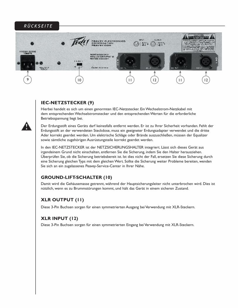
IEC-NETZSTECKER (9)Hierbei handelt es sich um einen genormten IEC-Netzstecker. Ein Wechselstrom-Netzkabel mit dem entsprechenden Wechselstromstecker und den entsprechenden Werten für die erforderliche Betriebsspannung liegt bei.
Der Erdungsstift eines Geräts darf keinesfalls entfernt werden. Er ist zu Ihrer Sicherheit vorhanden. Fehlt der Erdungsstift an der verwendeten Steckdose, muss ein geeigneter Erdungsadapter verwendet und die dritte Ader korrekt geerdet werden. Um elektrische Schläge oder Brände auszuschließen, müssen der Equalizer sowie sämtliche zugehörigen Ausrüstungsteile korrekt geerdet werden.
In den IEC-NETZSTECKER ist der NETZSICHERUNGSHALTER integriert. Lässt sich dieses Gerät aus irgendeinem Grund nicht einschalten, entfernen Sie die Sicherung, indem Sie den Halter herausziehen. Überprüfen Sie, ob die Sicherung betriebsbereit ist. Ist dies nicht der Fall, ersetzen Sie diese Sicherung durch eine Sicherung gleichen Typs mit dem gleichen Wert. Sollte die Sicherung weiter Probleme bereiten, wenden Sie sich an ein zugelassenes Peavey-Service-Center in Ihrer Nähe.
GROUND-LIFT-SCHALTER (10)Damit wird die Gehäusemasse getrennt, während der Hauptsicherungsleiter nicht unterbrochen wird. Dies ist nützlich, wenn es zu Brummstörungen kommt, und hält das Gerät in einem sicheren Zustand.
XLR OUTPUT (11)
Diese 3-Pin Buchsen sorgen für einen symmetrierten Ausgang bei Verwendung mit XLR-Steckern.
XLR INPUT (12)Diese 3-Pin Buchsen sorgen für einen symmetrierten Eingang bei Verwendung mit XLR-Steckern.
9 12 1211 1110

14
PV®231EQ Graphic EqualizerTECHNISCHE DATEN
Kanäle: 2 (stereo)
Bänder: 31 pro Kanal
Stecker: Symmetrierte Ein- und Ausgänge (XLR)
Frequenzmitten: 20 Hz, 25 Hz, 31.5 Hz, 40 Hz, 50 Hz, 63 Hz, 80 Hz, 100 Hz, 125 Hz, 160 Hz, 200 Hz, 250 Hz, 315 Hz, 400 Hz, 500 Hz, 630 Hz, 800 Hz, 1 kHz, 1.25 kHz, 1.5 kHz, 2 kHz, 2.5 kHz, 3.15 kHz, 4 kHz, 5 kHz, 6.3 kHz, 8 kHz, 10 kHz, 12.5 kHz, 16 kHz, 20 kHz
Regelbereich: Wählbar, +/-12 dB oder +/-6 dB
Eingangsimpedanz: 50k ohms
Ausgangsimpedanz: 600 ohms
Maximaler Ausgangspegel: +21 dB
Pegelregler: +/- 10 dB
Rauschabstand: >93 dB unbewertet
Verzerrung: 0.005%
Dämpfungsfilter: 18 dB/Oktave, butterworth
Tiefpassfilter: Variabel (10 Hz bis 250 Hz)
Hochpassfilter: Variabel (3 kHz bis 40 kHz)
Leistungsaufnahme: 15 watts

PV®231EQ Egaliseur graphique
DescriptionMerci d’avoir choisi l’égaliseur graphique PV 231EQ de Peavey Electronics. Le PV 231EQ est un égaliseur 2-canaux dans la lignée des produits Peavey, avec de faibles niveau de bruit et taux de distortion, le tout dans une unité de construction solide et pratique. Equipés de contrôles linéaires (fader) à point milieu capables de 12dB d’altération (cut ou boost), d’indicateurs LEDs de niveau, d’entrées et sorties symétrisées et d’interrupteur de mise en veille (bypass), le PV 231EQ est idéal pour de nombreuses applications, sur scène, en studio ou même pour améliorer le contrôle de votre propre système Hi-Fi.
Caractéristiques
➡ 2 canaux (31 bandes par canal)
➡ Filtres 1/3 octave centrés à la norme ISO
➡ Plage de fréquences d’égalisation de 20 Hz à 20 kHz
➡ Filtre à largeur constante (Q)
➡ de -12 dB à +12 dB d’altération par bande
➡ LEDs de niveau (de -12 à +17 dB)
➡ Filtre coupe-bas et coupe-haut variable
➡ Entrées et sorties XLR pour signal symétrisé
➡ Interrupteur de mise en veille (bypass) avec LED de status
➡ Contrôle de niveau de -10dB (cut) à +10dB (boost)
➡ Interrupteur de correspondance de masse (Ground lift)
Le procédé d’égalization Le PV 231EQ est un égaliseur graphique de sonorisation de salle. Vous devez toujours commencez une nouvelle égalisation de salle avec tous les contrôles linéaires (fader) en position milieu (aucune déformation du signal). En augmentant progressivement le niveau du système de diffusion, attendre tout départ d’effets de Larsen. Lorsque celui-ci survient, baissez légèrement le contrôle de la fréquence fautive, puis continuez à augmenter le niveau général du système, en répétant l’opération à chaque départ d’effets de Larsen, jusqu’à atteindre le niveau sonore désiré lors de la prestation.
Toute augmentation de fréquences (boost) est susceptible de prononcer l’apparition des effets de Larsen et peut facilement endommager votre système de diffusion. Prenez en compte la réponse en fréquence de votre système lors de vos réglages pour éviter des dommages éventuels et le gaspillage de puissance de votre amplification. Le filtre coupe-bas devrait être engagé pour l’utilisation avec la plupart des systèmes de diffusion, très peu d’entre eux gèrent les fréquences de 20 à 35 Hz.
NOTE: La qualité et tonalité de votre système ne dépend pas de votre égaliseur graphique. Tous les composants de votre système influent sur la qualité sonore de celui-ci, mais votre égaliseur graphique permet uniquement de remédier aux problèmes liés à la projection de votre signal sonore dans l’emplacement désigné.
FRANÇAIS

LEDs DE NIVEAU (1)Cet arrangement de LEDs vous indique le niveau entre –10 dB to +17 dB.
CONTROLE DE NIVEAU (2)Ce contrôle vous permet de réguler le niveau de votre signal dans la section égalisation.
La notion de gain unitaire est très importante pour tout appareil de traitement/diffusion de signal. Le procédé d’égalisation peut résulter en une perte de gain générale, qui peut être compensée par ce contrôle. L’utilisation de l’interrupteur de mise en veille (bypass) vous permet de déterminer la perte engendrée. Le contrôle de niveau devrait être positionné pour que l’activation/désactivation de votre égaliseur n’affecte pas le niveau général de votre signal.
FILTRE COUPE-BAS VARIABLE (3)Ce contrôle vous permet d’ajuster la fréquence de coupure du filtre coupe-bas intégré à votre unité. La pente de filtre est de 18 dB par octave quand celui-ci est engagé. Si engagé, ce filtre sera actif même si l’interrupteur
de mise en veille (bypass) est engagé.
FILTRE COUPE-HAUT VARIABLE (4)Ce contrôle vous permet d’ajuster la fréquence de coupure du filtre coupe-haut intégré à votre unité. La pente de filtre est de 18 dB par octave quand celui-ci est engagé. Si engagé, ce filtre sera actif même si l’interrupteur de mise en veille (bypass) est engagé.
SECTION D’EGALISATION (5)Ces contrôles linéaires sont précisemment calibrés et possédent un point milieu. Ils vous permettent de contrôler le gain de la fréquence correspondante entre -12 dB (cut) et +12 dB (boost) ou entre –6dB et +6dB selon la position du sélecteur RANGE.
INTERRUPTEUR DE MISE EN VEILLE (BYPASS - 6) This switch allows the signal to bypass all features except the LOW-CUT FILTER (4). When this switch is engaged, the signal is routed from INPUT (10 and 11) though the low-cut filter to the channel’s output. Bypass is indicated by illumination of LED above the switch.
REGISTRE DE FILTRE (7)Ce sélecteur vous permet de choisir l’amplitude de déformation de la section égalisation (+/-12 dB ou +/-6 dB), vous permettant d’obtenir une ergonomie optimale quelque soit le système de diffusion.
ALIMENTATION (8)Cet interrupteur permet de mettre votre unité sous/hors tension. Votre unité est active lorsque cet interrupteur est sur la position annotée ON, la LED rouge correspondante illuminée.
PA N N E A U A V A N T
5
1
1 2
2
3
3
4
45
6
6 8
7
7
ATTENTIONL'INTERRUPTEUR D'ALIMENTATION NE COUPE PAS CELLE-CI AUX DEUX BORNES ET DE L'ENERGIE ELECTRIQUE PEUT ETRE PRESENTE DANS CERTAINS COMPOSANTS APRES LA MISE HORS-TENSION.
PA N N E A U A R R I E R E
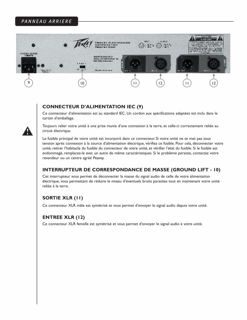
CONNECTEUR D’ALIMENTATION IEC (9)Ce connecteur d’alimentation est au standard IEC. Un cordon aux spécifications adaptées est inclu dans le carton d’emballage.
Toujours relier votre unité à une prise munie d’une connexion à la terre, et celle-ci correctement reliée au circuit électrique.
Le fusible principal de votre unité est incorporé dans ce connecteur. Si votre unité ne se met pas sous tension après connexion à la source d’alimentation électrique, vérifiez ce fusible. Pour cela, déconnecter votre unité, retirer l’habitacle du fusible du connecteur de votre unité, et vérifier l’état du fusible. Si le fusible est endommagé, remplacez-le avec un autre de même caractéristiques. Si le problème persiste, contactez votre revendeur ou un centre agréé Peavey.
INTERRUPTEUR DE CORRESPONDANCE DE MASSE (GROUND LIFT - 10) Cet interrupteur vous permet de déconnecter la masse du signal audio de celle de votre alimentation électrique, vous permettant de réduire le niveau d’éventuels bruits parasites tout en maintenant votre unité reliée à la terre.
SORTIE XLR (11)
Ce connecteur XLR mâle est symétrisé et vous permet d’envoyer le signal audio depuis votre unité.
ENTREE XLR (12)Ce connecteur XLR femelle est symétrisé et vous permet d’envoyer le signal audio à votre unité.
9 12 1211 1110

1
PV®231EQ Egaliseur GraphiqueSPECIFICATIONS
Canaux: 2 (stereo)
Bandes: 31 par canal
Connecteurs: entrées et sorties XLR symétrisées
Fréquences de Filtres: 20 Hz, 25 Hz, 31.5 Hz, 40 Hz, 50 Hz, 63 Hz, 80 Hz, 100 Hz, 125 Hz, 160 Hz, 200 Hz, 250 Hz, 315 Hz, 400 Hz, 500 Hz, 630 Hz, 800 Hz, 1 kHz, 1.25 kHz, 1.5 kHz, 2 kHz, 2.5 kHz, 3.15 kHz, 4 kHz, 5 kHz, 6.3 kHz, 8 kHz, 10 kHz, 12.5 kHz, 16 kHz, 20 kHz
Control Range: +/-12 dB ou +/-6 dB
Impédance d’entrée: 50k ohms
Impédance de sortie: 600 ohms
Niveau maximum de sortie: +21 dB
Contrôle de gain: +/- 10 dB
Rapport signal/bruit: >93 dB sans charge
Distortion: 0.005%
Pente de Filtres: 18 dB/octave, butterworth
Coupe-bas: Fréquence variable (de 10 Hz à 250 Hz)
Coupe-haut: Fréquence variable (de 3 kHz à 40 kHz)
Consommation: 15 watts

PV®231EQ Ecualizador gráfico
DescripciónGracias por adquirir un ecualizador gráfico PV 231EQ de Peavey Electronics. El PV 231EQ es un EQ de doble canal que incorpora el diseño legendario de Peavey de bajo ruido y baja distorsión. De construcción robusta, los PV 231EQs tienen faders de control dentados en el cento y ofrecen una ganancia seleccionable de ±6 dB o ±12 dB y un display LED indicador de nivel. Además incluye filtros de recorte de graves y agudos de estado variable, entradas y salidas XLR balanceadas, y conmutador de bypass. Los filtros del PV 231EQ están ajustados en frecuencias ISO centradas con un 3% de margen. Ya sea sobre el escenario, en el estudio o simplemente para retocar el sistema hi-fi de su hogar, el PV 231EQ está hecho para usted.
Características
➡ Doble canal (31 bandas por canal)
➡ Filtros de 1/3 de octava (centrados según ISO)
➡ Rango de ecualización efectiva de 20 Hz a 20 kHz
➡ Filtros Q constantes
➡ Rango de recorte/aumento seleccionable entre 6 dB o 12 dB
➡ LEDs de nivel (De -10 a +17 dB)
➡ Filtros de recorte de graves y agudos de estado variable
➡ Entradas y salidas XLR para operación balanceada
➡ Interruptor Bypass con LED de estatus
➡ Control de Nivel de recorte/aumento de 10 dB
➡ Interruptor de encendido de Tierra
Proceso de EcualizaciónSiempre comience el proceso de ecualización con todos los sliders en su posición central (respuesta plana). Incremente el volumen hasta que ocurra la retroalimentación, entonces disminuya el nivel de cada fader hasta que encuentre la frecuencia de retroalimentación. Disminuya el nivel de los faders con movimientos pequeños para evitar cambios drásticos en la calidad del sonido. Así mismo, los aumentos excesivos de frecuencias pueden generar retroalimentación.
Hay que tener cuidado cuando se trate de incrementar frecuencias que estén por debajo del punto de recorte de los transductores del sistema de altavoces. Las típicas cajas de refuerzo sonoro no están diseñadas para reproducir frecuencias de 20 Hz, y los transductores pueden ser dañados por sobrecargas en frecuencias graves. Los incrementos excesivos en frecuencias muy graves también pueden limitar el umbral del sistema entero. Encender el filtro de graves es la mejor manera de evitar estos problemas.
NOTA: Conseguir un tono superior, ausencia de retroalimentación y calidad de sonido puede no siempre ser posible con cualquier ecualizador gráfico. Todos los demás elementos deben ser de alta calidad y estar diseñados para la aplicación. Ninguna ecualización puede corregir una habitación con mala acústica, un mal posicionamiento entre los micrófonos y los altavoces, o corregir o cambiar completamente la curva de frecuencias de un altavoz mediocre.
ESPAÑOL

MEDIDOR LED DEL NIVEL DE SALIDA (1)Esta serie de LEDs indica el nivel de salida de –12 dB a + 17 dB.
CONTROL DE NIVEL (2)Este control calibrado regula la ganancia general de la SECCIÓN DEL ECUALIZADOR.
La ganancia unitaria a través de la cadena de la señal se puede mantener recuperando la ganancia de la señal en este punto. El proceso de ecualización puede dar como resultado una pérdida de señal perceptible. Para compensar esta pérdida, active el interruptor de BYPASS (6) y compare el nivel de la señal con el nivel del ecualizador. Incremente el control de GANANCIA hasta que el ecualizador aproxime el nivel de la señal de bypass. Deje que sus oídos sean su guía.
FILTRO VARIABLE DE RECORTE DE GRAVES (3)Este control ajusta el filtro variable de recorte de graves que no acepta frecuencias por debajo del punto seleccionado. La pendiente del filtro (roll-off) es de 18 dB por octava. Este filtro operará incluso cuando el
interruptor de BYPASS (6) esté activado.
FILTRO VARIABLE DE RECORTE DE AGUDOS (4)Este control ajusta el filtro variable de recorte de agudos que no acepta frecuencias por encima del punto seleccionado. La pendiente del filtro (roll-off) es de 18 dB por octava. Este filtro operará incluso cuando el interruptor de BYPASS (6) esté activado.
SECCIÓN DEL ECUALIZADOR (5)Estos controles calibrados con centro marcado ajustan la cantidad de incremento o recorte de sus respectivas frecuencias. Son ajustables desde -12 dB (recorte) hasta +12 dB (incremento) o -6 dB (recorte) hasta 6 dB (incremento) dependiendo de la posición del interruptor Range.
BYPASS (6)Este interruptor permite que la señal pase por la unidad sin ser afectada, a excepción del FILTRO DE RECORTE DE GRAVES (3). Cuando este interruptor está activado, la señal es enviada de la ENTRADA (10 y 11), a través del filtro de graves, a las salidas de canal. El Bypass es indicado mediante la iluminación del LED situado sobre el interruptor.
RANGO (7)Este interruptor permite la selección del rango (+/-12 dB o +/-6 dB) en los controles de la Sección de Ecualización. Esto proporciona al operador la posibilidad de usar un control de ecualización más fino.
CORRIENTE (8)Este interruptor de dos posiciones suministra corriente a la unidad cuando está en la posición de encendido (ON). El LED verde adyacente indica que la unidad está recibiendo corriente.
PA N E L F R O N T A L
5
1
1 2
2
3
3
4
45
6
6 8
7
7
ADVERTENCIAEL INTERRUPTOR ON/OFF DE ESTE APARATO NO ROMPE AMBOS LADOS DEL CIRCUITO. ENERGÍA PELIGROSA PUEDE ESTAR PRESENTE DENTRO DE LA CAJA CUANDO EL INTERRUPTOR DE ENCENDIDO ESTÉ EN LA POSICIÓN OFF.

PA N E L T R A S E R O
CONECTOR PRINCIPAL DE CORRIENTE (9)Este es un conector de corriente IEC estándar. Un cable de CA con los requisitos necesarios de voltaje y el enchufe apropiado se incluye en el paquete.
Nunca retire la tercera patilla de tierra de ningún aparato. Ésta ha sido incluida por su seguridad. Si la fuente de corriente no cuenta con una conexión de tierra, se debe utilizar un adaptador con tierra y el tercer contacto debe ser aterrizado propiamente. Para prevenir el riesgo de electrocución o fuego, siempre hay que asegurarse de que el ecualizador y todo el equipo con él asociado esté apropiadamente aterrizado.
Incorporado dentro del CONECTOR PRINCIPAL DE CORRIENTE se encuentra la CÁPSULA DEL FUSIBLE PRINCIPAL. Si es incapaz de encender esta unidad por la razón que sea, retire el fusible sacando la cápsula. Compruebe que el fusible funciona correctamente. Si no es así, sustitúyalo por un fusible de características y valor apropiados. Si el fusible continúa fallando, contacte su Servicio Técnico Oficial de Peavey más cercano.
INTERRUPTOR DE ENCENDIDO DE TIERRA (10)Éste encenderá el circuito de Tierra manteniendo la Seguridad a Tierra Principal intacta. Esto es útil cuando hay zumbido presente, y le mantendrá a salvo cuando opere la unidad.
ENTRADA XLR (11)Estos conectores macho de 3 pines proporcionan entradas balanceadas cuando se usan con conectores
XLR hembra.
SALIDA XLR (12)Estos conectores hembra de 3 pines proporcionan salidas balanceadas cuando se usan con conectores XLR macho.
9 12 1211 1110

22
Ecualizador Gráfico PV®231EQ ESPECIFICACIONES
Canales: 2 (estéreo)
Bandas: 31 por canal
Conectores: Salidas y entradas XLR balanceadas
Frecuencias Filtradas: 20 Hz, 25 Hz, 31.5 Hz, 40 Hz, 50 Hz, 63 Hz, 80 Hz, 100 Hz, 125 Hz, 160 Hz, 200 Hz, 250 Hz, 315 Hz, 400 Hz, 500 Hz, 630 Hz, 800 Hz, 1 kHz, 1.25 kHz, 1.5 kHz, 2 kHz, 2.5 kHz, 3.15 kHz, 4 kHz, 5 kHz, 6.3 kHz, 8 kHz, 10 kHz, 12.5 kHz, 16 kHz, 20 kHz
Rango de Control: Seleccionable entre +/-12 dB o +/-6 dB
Impedancia de Entrada: 50k ohms
Impedancia de Salida: 600 ohms
Máximo Nivel de Salida: +21 dB
Control de Nivel: +/- 10 dB
Relación Señal-Ruido: >93 dB unweighted
Distorsión: 0.005%
Pendiente de los Filtros: 18 dB/octave, diseño butterworth
Recorte de graves: Estado variable (de 10 Hz a 250 Hz)
Recorte de agudos: Estado variable ( de 3 kHz a 40 kHz)
Consumo de Potencia: 15 vatios

日本語
PV®231EQ グラフィックイコライザ 概要
Peavey Electronics PV 23IEQ グラフィックイコライザをお買い上げいただきありがとうございます。PV 23IEQ は、Peavey の特徴である低ノイズ、低歪み設計を採用したデュアルチャンネル EQ です。頑丈に作られた PV 231EQ は、中央デテントのフェーダーコントロールを備え、±6 dB または ±12 dB ゲインを選択でき、LED ディスプレイでレベルを表示します。このほか、状態可変ローカット、ハイカットフィルタ、XLR 平衡入出力、バイパススイッチを備えています。PV 231EQ フィルタは ISOセンター周波数、精度3% 内に設定されています。ステージでもスタジオでも、自宅のハイファイシステムに手を加えるときでも、PV 231EQ は最適な EQ です。
特徴:➡ デュアルチャンネル (各チャンネル31 バンド)
➡ 1/3 オクターブフィルタセット (ISO センター)
➡ イコライゼーション有効範囲20 Hz ~ 20 kHz
➡ 定 Q フィルタ
➡ 6 dB または 12 dB カット/ブースト範囲選択可能
➡ レベル LED (-10 ~ +17 dB)
➡ 状態可変ロー/ハイカットフィルタ
➡ XLR 入出力平衡動作
➡ ステータス LED付バイパススイッチ
➡ 10 dB ブースト /10 dB カット レベルコントロール
➡ グランドリフトスイッチ
イコライゼーションプロセスイコライゼーションは、常に、すべてのスライダを中央デテント (フラットレスポンス) 位置にして始めます。本体のフィードバックが始まるまでレベ
ルを調整してから、フィードバック周波数が見つかるまで各フェーダーを下げます。音質を損なうような影響を与えないように、フェーダーは少
しずつ下げます。同様に、周波数をブーストしすぎるとフィードバックが生じることがあります。
スピーカーシステムのトランスデューサカットオフ未満で周波数ブーストを試すときは注意してください。サウンドを強化する一般的なエンクロ
ージャは、20 Hz での性能を考慮しておらず、低周波の過剰ブーストによりトランスデューサが破損する可能性があります。かなり低い周波
数での過剰なブーストは、システム全体のヘッドルームを制限することがあります。ローカットフィルタは、このような問題をなくすための最適な
方法です。
注: どのようなグラフィックイコライザを使用しても、優れたトーナリティ、フィードバックのない状態、および音質の良いシステムを実現すること
はできないでしょう。他のシステムコンポーネントは、すべて、高品質であり、用途に応じて設計されている必要があります。イコライゼーション
の程度のかかわらず、音響的に問題のある部屋やマイク/スピーカー構成を改良すること、または音の良くないスピーカーのレスポンス曲線
を完ぺきに補正することはできません。

レベル LED メーター (1)
この LED アレイは -10 dB ~ +17 dBのレベルを示します。
LEVEL コントロール (2)
EQUALIZER セクション (5)全体のゲインを調整する校正済みデテントコントロールです。信号チェーンのユニティゲインは、この点での喪失信号ゲインを回復することで維持されます。イコライゼーションにより信号ロスが目立つ可能性はあります。このロスを補うため、BYPASS (6) スイッチを加え、信号レベルをイコライズ後のレベルと比較します。イコライズ後のレベルがバイパスレベルに近づくまで GAIN コントロールを上げます。耳をガイドにして調整してください。
可変 LOW-CUT フィルタ (3)
このコントロールは、選択点より下の周波数を除外する状態可変ローカットフィルタを調整します。周波数ロールオフはオクターブ当たり 18 dB です。このフィルタは関連 BYPASS (6) スイッチとも連動します。
可変HIGH-CUT フィルタ (4)
このコントロールは、選択点より上の周波数を除外する状態可変ハイカットフィルタを調整します。周波数ロールオフはオクターブ当たり 18 dB です。このフィルタは関連 BYPASS (6) スイッチとも連動します。
EQUALIZER セクション (5)
それぞれの周波数でカットまたはブーストの量を調整する校正済みデテントコントロールです。レンジスイッチの位置に応じて、-12 dB (カット) ~ +12 dB (ブースト) または -6 dB (カット) to 6 dB (ブースト) の範囲で調整できます。
BYPASS (6)
信号は、このスイッチにより、LOW-CUT フィルタ (4)を除くすべての機能をバイパスします。このスイッチがオンのとき、信号は INPUT (10、11)からローカットフィルタを通り、チャンネルの出力までルーティングされます。スイッチの上のLED によってバイパス状態が示されます。
RANGE (7)
イコライザセクションのコントロールのレンジ (+/-I2 dB ~ +/-6 dB)を選択するスイッチです。イコライゼーションを細かく調整することができます。
POWER (8)
ON 位置のとき、主電源を本体に供給する2ポジションロッカースイッチです。隣接する赤色 LED は、主電源が入っていることを示します。
フロントパネル
5
1
1 2
2
3
3
4
45
6
6 8
7
7
警告本機の ON/OFF スイッチは、主電源の両側を切断することはありません。電源スイッチがオフ位置のとき、エンクロージャ内部のエネルギーが危険な状態になることがあります。

IEC MAINS CONNECTOR (9)
標準IEC 電源コネクタです。付属品として、動作電圧に対応するAC プラグと定格の AC 電源コードが含まれています。
どのような機器でも、グランドピン(接地ピン)は決して取り外さないでください。グランドピンは安全のために取り付けてあります。使用するコンセントにグランドピンがない場合は、適切な接地アダプタを使用し、3番目のワイヤを正しく接地してください。感電や火災の危険をなくすため、イコライザおよび関連するすべての機器が正しく接地されているか常に確認してください。
このIEC 電源コネクタには電源ヒューズホールダが組み込まれています。本体の電源を入れることができない場合には、ホールダから引き出してヒューズを取り外します。ヒューズが使用できる状態か確認します。使用できない場合は、対応する値、定格のヒューズと交換します。ヒューズが繰り返し切れる場合は、最寄りの指定Peaveyサービスセンターにお問い合わせください。
GROUND LIFT スイッチ (10)
「主電源セーフティグランド」はそのままの状態で、回路グランドをリフトします。ハムがある場合に便利です。また動作中に本体の安全を守ります。
XLR OUTPUT (11)
XLRメスコネクタと併用することで平衡出力を与える3ピンオスコネクタです。
XLR INPUT (12)
XLRオスコネクタと併用することで平衡出力を与える3ピンメスコネクタです。
リアパネル
9 12 1211 1110

PV ®231EQ グラフィックイコライザ
仕様
チャンネル: 2 (ステレオ)
バンド: チャンネル当たり31
コネクタ: XLR 平衡入出力
周波数センター: 20 Hz, 25 Hz, 31.5 Hz, 40 Hz, 50 Hz, 63 Hz, 80 Hz, 100 Hz, 125 Hz, 160 Hz, 200 Hz, 250 Hz, 315 Hz, 400 Hz, 500 Hz, 630 Hz, 800 Hz, 1 kHz, 1.25 kHz, 1.5 kHz, 2 kHz, 2.5 kHz, 3.15 kHz, 4 kHz, 5 kHz, 6.3 kHz, 8 kHz, 10 kHz, 12.5 kHz, 16 kHz, 20 kHz
コントロール範囲: +/-12 dB または +/-6 dB選択可能
入力インピーダンス: 50k オーム
出力インピーダンス: 600 オーム
最大出力レベル: +21 dB
レベルコントロール: +/- 10 dB
信号ノイズ比: >93 dB ウェイトなし
歪み: 0.005%
ロールオフフィルタ: 18 dB/オクターブ、バターワース
ローカット: 状態可変 (10 Hz ~ 250 Hz)
ハイカット: 状態可変 (3 kHz ~ 40 kHz)
消費電力: 15 ワット


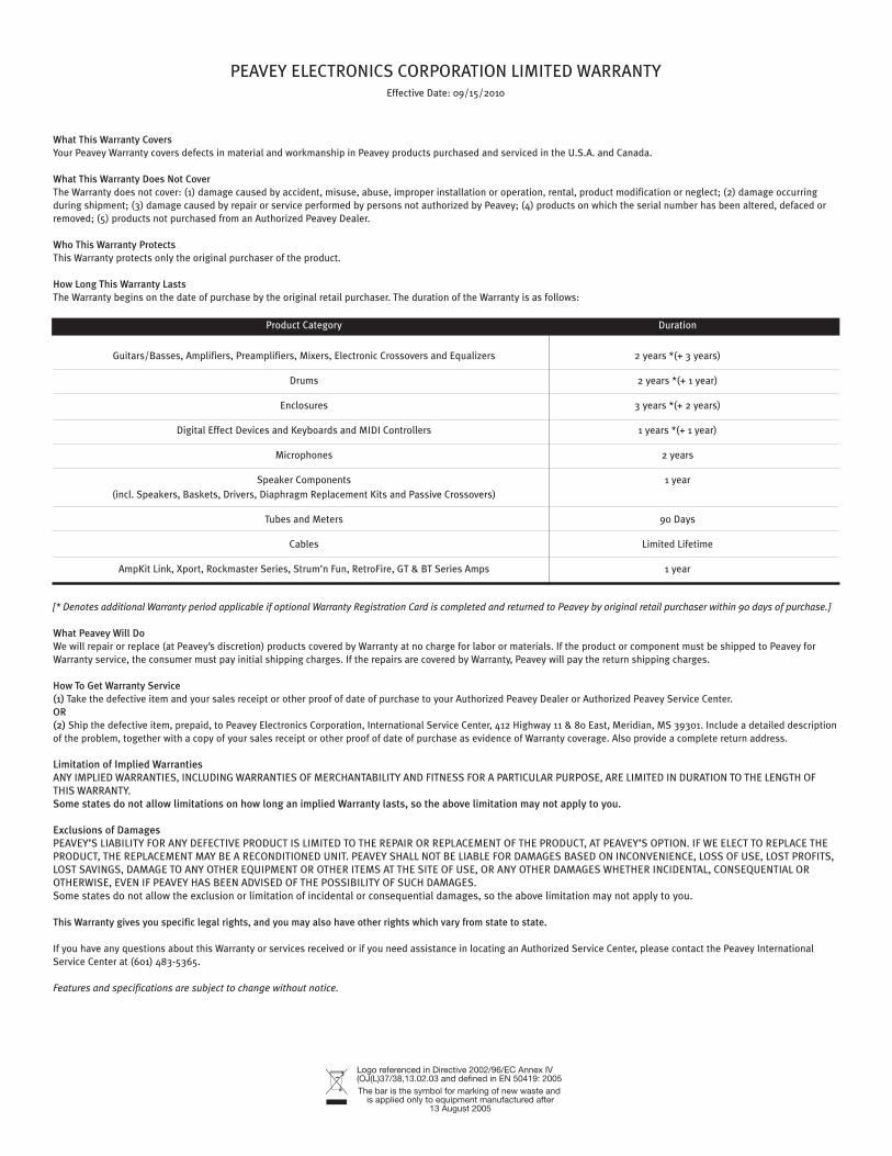
PEAVEY ELECTRONICS CORPORATION LIMITED WARRANTYEffective Date: 09/15/2010
What This Warranty CoversYour Peavey Warranty covers defects in material and workmanship in Peavey products purchased and serviced in the U.S.A. and Canada.
What This Warranty Does Not CoverThe Warranty does not cover: (1) damage caused by accident, misuse, abuse, improper installation or operation, rental, product modification or neglect; (2) damage occurring during shipment; (3) damage caused by repair or service performed by persons not authorized by Peavey; (4) products on which the serial number has been altered, defaced or removed; (5) products not purchased from an Authorized Peavey Dealer.
Who This Warranty ProtectsThis Warranty protects only the original purchaser of the product.
How Long This Warranty LastsThe Warranty begins on the date of purchase by the original retail purchaser. The duration of the Warranty is as follows:
Product Category Duration
Guitars/Basses, Amplifiers, Preamplifiers, Mixers, Electronic Crossovers and Equalizers 2 years *(+ 3 years)
Drums 2 years *(+ 1 year)
Enclosures 3 years *(+ 2 years)
Digital Effect Devices and Keyboards and MIDI Controllers 1 years *(+ 1 year)
Microphones 2 years
Speaker Components 1 year (incl. Speakers, Baskets, Drivers, Diaphragm Replacement Kits and Passive Crossovers)
Tubes and Meters 90 Days
Cables Limited Lifetime
AmpKit Link, Xport, Rockmaster Series, Strum’n Fun, RetroFire, GT & BT Series Amps 1 year
[* Denotes additional Warranty period applicable if optional Warranty Registration Card is completed and returned to Peavey by original retail purchaser within 90 days of purchase.]
What Peavey Will DoWe will repair or replace (at Peavey’s discretion) products covered by Warranty at no charge for labor or materials. If the product or component must be shipped to Peavey for Warranty service, the consumer must pay initial shipping charges. If the repairs are covered by Warranty, Peavey will pay the return shipping charges.
How To Get Warranty Service(1) Take the defective item and your sales receipt or other proof of date of purchase to your Authorized Peavey Dealer or Authorized Peavey Service Center.OR(2) Ship the defective item, prepaid, to Peavey Electronics Corporation, International Service Center, 412 Highway 11 & 80 East, Meridian, MS 39301. Include a detailed description of the problem, together with a copy of your sales receipt or other proof of date of purchase as evidence of Warranty coverage. Also provide a complete return address.
Limitation of Implied WarrantiesANY IMPLIED WARRANTIES, INCLUDING WARRANTIES OF MERCHANTABILITY AND FITNESS FOR A PARTICULAR PURPOSE, ARE LIMITED IN DURATION TO THE LENGTH OF THIS WARRANTY.Some states do not allow limitations on how long an implied Warranty lasts, so the above limitation may not apply to you.
Exclusions of DamagesPEAVEY’S LIABILITY FOR ANY DEFECTIVE PRODUCT IS LIMITED TO THE REPAIR OR REPLACEMENT OF THE PRODUCT, AT PEAVEY’S OPTION. IF WE ELECT TO REPLACE THE PRODUCT, THE REPLACEMENT MAY BE A RECONDITIONED UNIT. PEAVEY SHALL NOT BE LIABLE FOR DAMAGES BASED ON INCONVENIENCE, LOSS OF USE, LOST PROFITS, LOST SAVINGS, DAMAGE TO ANY OTHER EQUIPMENT OR OTHER ITEMS AT THE SITE OF USE, OR ANY OTHER DAMAGES WHETHER INCIDENTAL, CONSEQUENTIAL OR OTHERWISE, EVEN IF PEAVEY HAS BEEN ADVISED OF THE POSSIBILITY OF SUCH DAMAGES.Some states do not allow the exclusion or limitation of incidental or consequential damages, so the above limitation may not apply to you.
This Warranty gives you specific legal rights, and you may also have other rights which vary from state to state.
If you have any questions about this Warranty or services received or if you need assistance in locating an Authorized Service Center, please contact the Peavey International Service Center at (601) 483-5365.
Features and specifications are subject to change without notice.
Logo referenced in Directive 2002/96/EC Annex IV(OJ(L)37/38,13.02.03 and defined in EN 50419: 2005The bar is the symbol for marking of new waste and
is applied only to equipment manufactured after13 August 2005

U.S. CUSTOMER WARRANTY REGISTRATION
Optional Product Extended Warranty RegistrationGive us some information and put your extended warranty into effect!
9. How would you describe your level of musicianship/technical expertise?
1.
First Name Initial Last Name
Street Address
City State/Province Postal Code
( ) Telephone Number E-mail Address
( ) - -Fax Number Date of birth
2.
Model Serial #
Date of Purchase Price Paid
3.
Name of store where purchased
City State
4. Top two (2) reasons why you purchased from this store/dealer:
8. Which other brands/models did you consider?
❒ Past favorable experience❒ Best price❒ Advertised special❒ Convenient location❒ Received as a gift❒ Other
❒ Availability of product❒ Friend/Relative’s recommendation❒ Store credit card❒ Knowledgeable staff❒ Availability of lessons❒ Technical instruction
6. What two (2) factors most influenced your purchase of this product?
❒ Peavey brand name ❒ Craftsmanship❒ Features for price❒ Bundled accessories❒ Sound quality
❒ Product appearance❒ Durability❒ Prior experience with Peavey❒ Packaging❒ Other
❒ Beginner - Never played or taken less than one (1) year of lessons❒ Intermediate - One (1) to five (5) years of lessons or playing❒ Advanced - More than five (5) years of lessons or playing; play professionally
10. Education: (select best answer)
❒ High school❒ Some college❒ Completed college❒ Graduate school
Gender ❒ M ❒ F
11. Which best describe your family income? (select best answer)
12. Which of the following is your primary source of information on musical products: (select best answer)
Please take a few minutes to fill out this information/survey sheet to help us get to know and serve you better.
To save time, submit your warranty registration online at www.peavey.com/support/warrantyregistration
❒ Under $15,000 ❒ $15,000 - $24,999❒ $25,000 - $34,999❒ $35,000 - $49,999❒ $50,000 - $74,999
❒ Television ❒ Radio❒ Internet❒ Newspaper❒ Magazines
❒ Mail order catalogs❒ Direct mail❒ Literature from manufacturer❒ Other
❒ $75,000 - $99,999❒ $100,000 - $149,999❒ Over - $150,000
13. What is your main motivation for buying new equipment?
❒ Replacing old product ❒ Want new and leading edge equipment❒ Fullfill a specific need❒ Supplement existing products❒ Value
❒ Impulse❒ Need for improved performance❒ New technology❒ Availability of product❒ Other
7. How did you learn about this Peavey product? (select best answer)
❒ Magazine review ❒ Newspaper review❒ Radio advertisement ❒ Advertised special❒ Friend/Relative’s recommendation❒ Salesperson’s recommendation
❒ Teacher’s recommendation❒ Catalog or flyer❒ Saw in store❒ Use by professional❒ Other
15. In your opinion, what could Peavey do to improve its products and/or service? Please use the space below to tell us your answer.
Thank you for taking the time to fill out our survey! Don’t forget to fold and tape (with Peavey address facing out), affix postage stamp and drop in the mail!
5. Where do you most often shop for music and sound products?
❒ Independent retailer❒ Mass market retailer❒ Mail order magazines
❒ Newspaper ads❒ Internet/Web sites❒ Other
Revised 1/11
14. Please list your three most frequently visited Web sites.
1. http://__________________________________________
2. http://__________________________________________
3. http://__________________________________________
Logo referenced in Directive 2002/96/EC Annex IV(OJ(L)37/38,13.02.03 and defined in EN 50419: 2005The bar is the symbol for marking of new waste and
is applied only to equipment manufactured after13 August 2005

Peavey Electronics Corporation
Attn: Warranty DepartmentP.O. Box 5108
Meridian, Ms 39302-5108
FROM:Place
PostageHere