
PUTTING A STOP TO ENERGY WASTE - Legrand … · 4 Vacancy/occupancy mode selection Most Legrand...
36
THE GLOBAL SPECIALIST IN ELECTRICAL AND DIGITAL BUILDING INFRASTRUCTURES LIGHTING MANAGEMENT SENSORS DESIGN AND APPLICATION GUIDE PUTTING A STOP TO ENERGY WASTE
Transcript of PUTTING A STOP TO ENERGY WASTE - Legrand … · 4 Vacancy/occupancy mode selection Most Legrand...

THE GLOBAL SPECIALIST IN ELECTRICAL AND DIGITAL BUILDING INFRASTRUCTURES
LIGHTING MANAGEMENT SENSORSDESIGN AND APPLICATION GUIDE
PUTTING A STOP TO ENERGY WASTE

CONTENTS p. 1 Design steps for implementing
motion and lighting management solutions
p. 13 Application examples for specific building spaces
p. 22 Catalogue pages
Our vision at Legrand is to provide products and services that make buidlings more energy efficient. We are committed to limiting energy waste.
This document will assist you in selecting, laying out, commissionning and installing a lighting management solution. It will also assist you in defining and implementing the optimum lighting management solution for a specific type of building space.
according to EN 1519360%SAVINGS

1DESIGN AND APPLICATION GUIDE
Our wide range of switch sensors, comprising of motion and lighting management sensors, is designed to reduce the amount of time lighting is left on active unnecessarily, for example when an area is unoccupied or if there is sufficient natural light.
Our lighting management sensors can be used to: monitor the detection area for occupancy When a person is sensed the lighting is automatically switched on.
In case of sensors equipped with a built in light level sensor, the lighting will be kept off when enough natural light is available.
When the area is vacated the lighting is switched off after a preset time delay.
control lighting (up to 60% savings on lighting energy costs according to EN15193).
control HVAC circuits and roller blind circuits (either via the sensor or a room controller).
The Legrand range includes motion or lighting management sensors to suit any area and control your lighting efficiently.
DESIGN STEPS FOR IMPLEMENTING MOTION AND LIGHTING MANAGEMENT SOLUTIONS
1
2 CHOOSE THE RIGHT SWITCH SENSOR
3
4
ASSESS THE SPACE CHARACTERISTICS
LIGHTING MANAGEMENT SENSORS
CONFIGURETHE SENSORS
DEFINE THE BEST LOCATION
2
ASSESS THE SPACE
CHARACTERISTICS
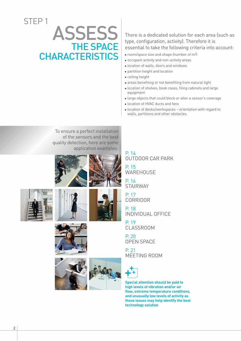
Special attention should be paid to high levels of vibration and/or air flow, extreme temperature conditions, and unusually low levels of activity as these issues may help identify the best technology solution
To ensure a perfect installation of the sensors and the best
quality detection, here are some application examples:
room/space size and shape (number of m²) occupant activity and non-activity areas location of walls, doors and windows partition height and location ceiling height areas benefiting or not benefiting from natural light location of shelves, book cases, filing cabinets and large equipment
large objects that could block or alter a sensor’s coverage location of HVAC ducts and fans location of desks/workspaces – orientation with regard to walls, partitions and other obstacles.
STEP 1There is a dedicated solution for each area (such as type, configuration, activity). Therefore it is essential to take the following criteria into account:
P. 14 OUTDOOR CAR PARK
P. 15 WAREHOUSE
P. 16 STAIRWAY
P. 17 CORRIDOR
P. 18 INDIVIDUAL OFFICE
P. 19 CLASSROOM
P. 20 OPEN SPACE
P. 21 MEETING ROOM
3DESIGN AND APPLICATION GUIDE
CHOOSE
THE RIGHT SENSOR
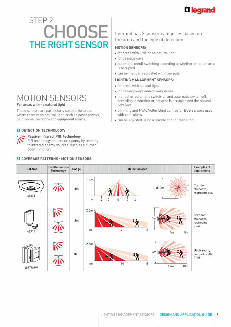
Passive Infrared (PIR) technologyPIR technology detects occupancy by reacting to infrared energy sources, such as a human body in motion.
2 COVERAGE PATTERNS - MOTION SENSORS
1 DETECTION TECHNOLOGY:
MOTION SENSORS
48803
8m
2.5m
m: 4 2 1 0 1 2 4
Ø: 8mCorridor, stairways, restrooms etc.
48911
8m
.Corridor, stairways, restrooms (IP42)
488TRI3W
18m
1010
1818
.Utility room, car park, cellar (IP55)
STEP 2
MOTION SENSORS:
LIGHTING MANAGEMENT SENSORS:
LIGHTING MANAGEMENT SENSORS
Legrand has 2 sensor categories based on the area and the type of detection: for areas with little or no natural light. for passageways. automatic on/off switching according to whether or not an area is occupied.
can be manually adjusted with trim pots
for areas with natural light. for passageways and/or work areas. manual or automatic switch-on and automatic switch-off, according to whether or not area is occupied and the natural light level.
dimming and HVAC/roller blind control for BUS sensors used with controllers.
can be adjusted using a remote configuration tool.
For areas with no natural light
These sensors are particularly suitable for areas where there is no natural light, such as passageways, bathrooms, corridors and equipment rooms.
Cat.Nos Installation type Technology Range Detection area Examples of
applications
4
Vacancy/occupancy mode selectionMost Legrand sensors can work using occupancy mode (by default) or vacancy mode.
Occupancy mode means that lights are automatically switched on or off according to occupancy.
Vacancy mode means that lights are manually switched on and automatically switched off. Vacancy mode offers extra energy savings.
LIGHTING MANAGEMENT SENSORS
Passive Infrared (PIR) technologyPIR technology detects occupancy by reacting to infrared energy sources, such as a human body in motion.
Dual technology (DT)Sensors that employ PIR + US sensing technologies are usually referred to as “dual technology”. Our dual technology ensures maximum sensitivity and coverage in tough applications for optimum reliability and energy saving.
2 PRODUCT FEATURES
2-1. Occupancy and vacancy detection
1 DETECTION TECHNOLOGY
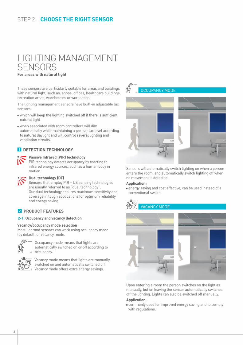
OCCUPANCY MODE
VACANCY MODE
Sensors will automatically switch lighting on when a person enters the room, and automatically switch lighting off when no movement is detected.Application: energy saving and cost effective, can be used instead of a conventional switch.
Upon entering a room the person switches on the light as manually, but on leaving the sensor automatically switches off the lighting. Lights can also be switched off manually.Application: commonly used for improved energy saving and to comply with regulations.
STEP 2 _ CHOOSE THE RIGHT SENSOR
The lighting management sensors have built-in adjustable lux sensors:
which will keep the lighting switched off if there is sufficient natural light
when associated with room controllers will dim automatically while maintaining a pre-set lux level according to natural daylight and will control several lighting and ventilation circuits.
For areas with natural light
These sensors are particularly suitable for areas and buildings with natural light, such as: shops, offices, healthcare buildings, recreation areas, warehouses or workshops.
5DESIGN AND APPLICATION GUIDE
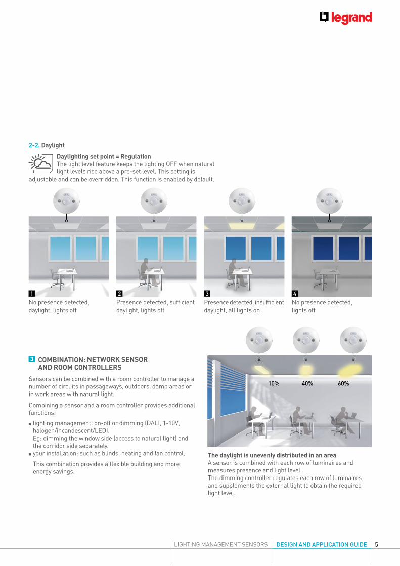
3 COMBINATION: NETWORK SENSOR AND ROOM CONTROLLERS
2-2. Daylight
Daylighting set point = RegulationThe light level feature keeps the lighting OFF when natural light levels rise above a pre-set level. This setting is
adjustable and can be overridden. This function is enabled by default.
No presence detected, daylight, lights off
Presence detected, sufficient daylight, lights off
No presence detected, lights off
Presence detected, insufficient daylight, all lights on
10% 40% 60%
1 32 4
Combining a sensor and a room controller provides additional functions:
lighting management: on-off or dimming (DALI, 1-10V, halogen/incandescent/LED). Eg: dimming the window side (access to natural light) and the corridor side separately.
your installation: such as blinds, heating and fan control.
This combination provides a flexible building and more energy savings.
LIGHTING MANAGEMENT SENSORS
The daylight is unevenly distributed in an areaA sensor is combined with each row of luminaires and measures presence and light level.The dimming controller regulates each row of luminaires and supplements the external light to obtain the required light level.
Sensors can be combined with a room controller to manage a number of circuits in passageways, outdoors, damp areas or in work areas with natural light.
6
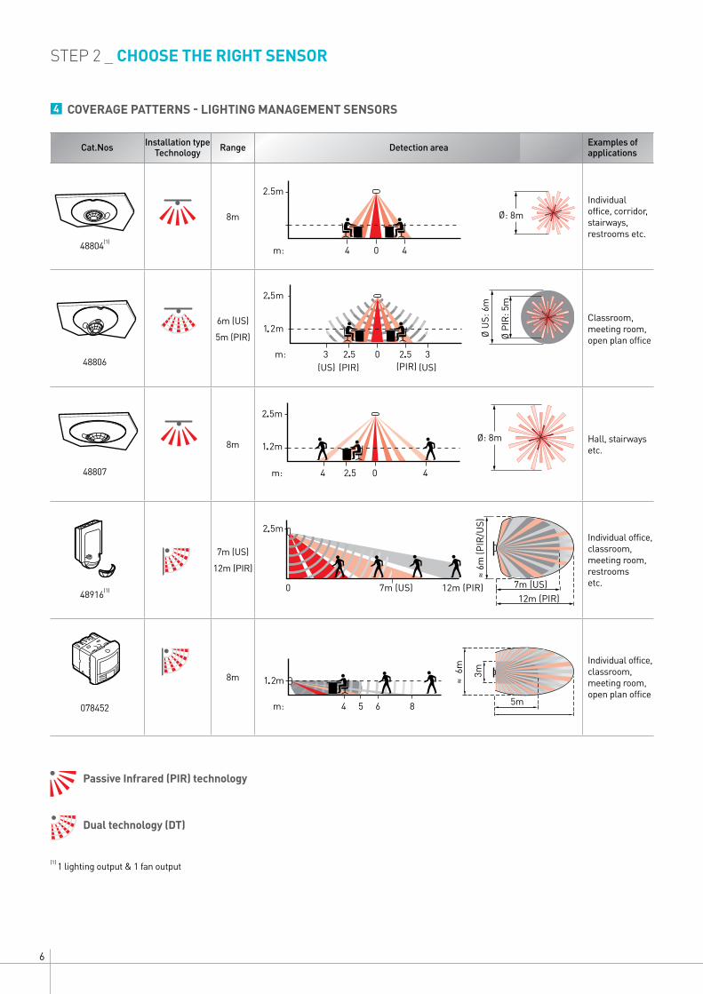
4 COVERAGE PATTERNS - LIGHTING MANAGEMENT SENSORS
48804(1)
8m
2.5m
m:
: 8m
Individual office, corridor, stairways, restrooms etc.
48806
6m (US)
5m (PIR)
Classroom, meeting room, open plan office
48807
8m Hall, stairways etc.
48916(1)
7m (US)
12m (PIR)
.Individual office, classroom, meeting room, restrooms etc.
078452
8m
Individual office, classroom, meeting room, open plan office
(1) 1 lighting output & 1 fan output
STEP 2 _ CHOOSE THE RIGHT SENSOR
Passive Infrared (PIR) technology
Dual technology (DT)
.
.
. .
.
.
.
.
Cat.Nos Installation type Technology Range Detection area Examples of
applications
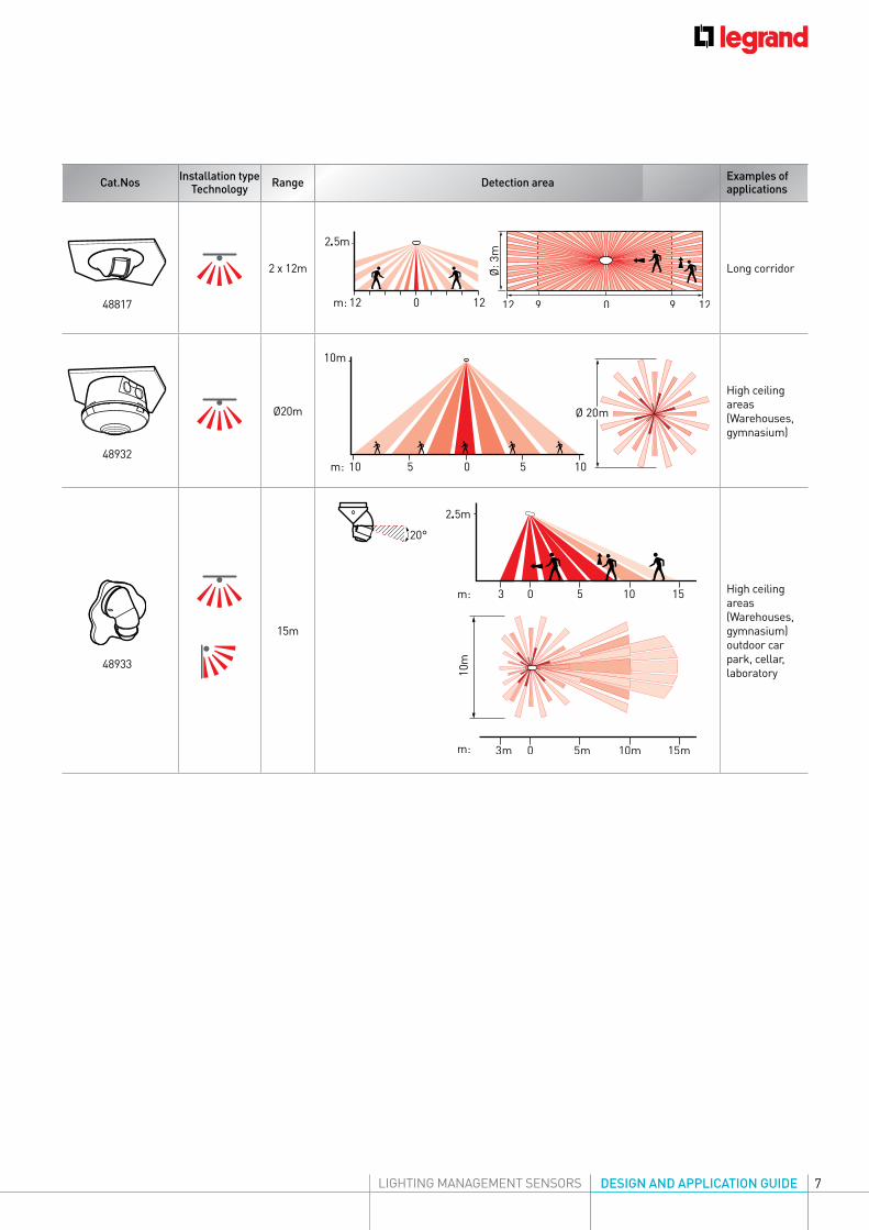
7DESIGN AND APPLICATION GUIDELIGHTING MANAGEMENT SENSORS
48817
2 x 12m
.
Long corridor
48932
Ø20m
High ceiling areas(Warehouses, gymnasium)
48933
15m
.
High ceiling areas(Warehouses, gymnasium) outdoor car park, cellar, laboratory
Cat.Nos Installation type Technology Range Detection area Examples of
applications
8
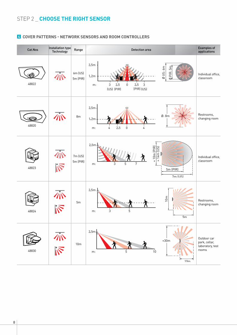
4 COVER PATTERNS - NETWORK SENSORS AND ROOM CONTROLLERS
48822
6m (US)
5m (PIR)
.
.
. .
Individual office, classroom
48820
8m Restrooms, changing room
48823
7m (US)
5m (PIR)Individual office, classroom
48824
5m
.
Restrooms, changing room
48830
10m
.Outdoor car park, cellar, laboratory, test rooms
STEP 2 _ CHOOSE THE RIGHT SENSOR
.
.
.
.
Cat.Nos Installation type Technology Range Detection area Examples of
applications
9DESIGN AND APPLICATION GUIDELIGHTING MANAGEMENT SENSORS
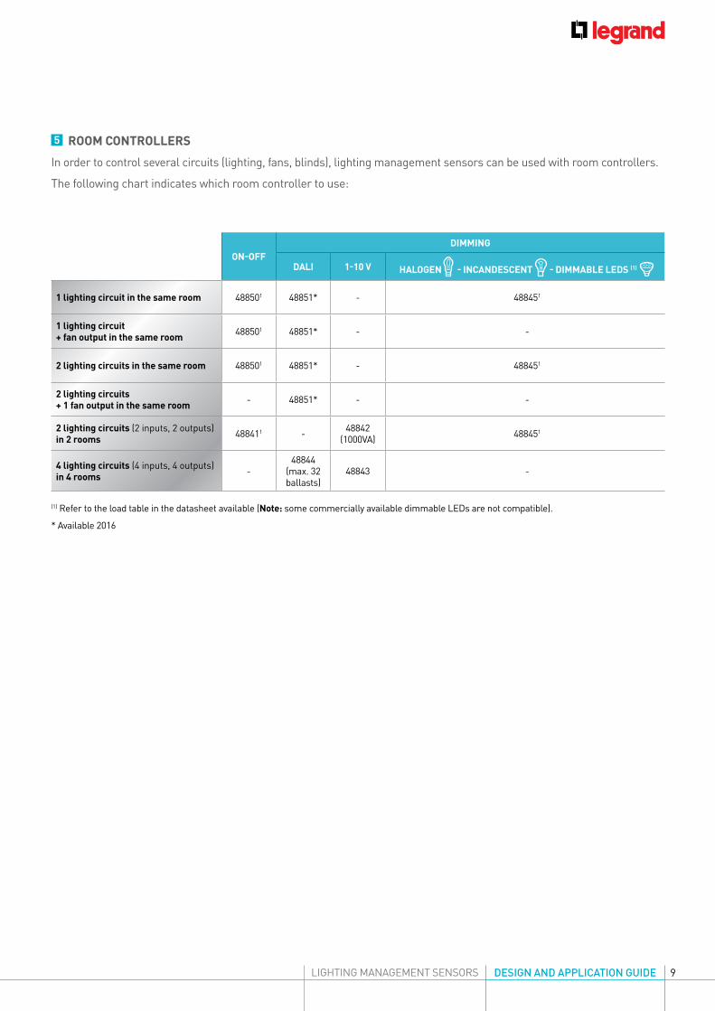
ON-OFFDIMMING
DALI 1-10 V HALOGEN - INCANDESCENT - DIMMABLE LEDS (1)
1 lighting circuit in the same room 488501 48851* - 488451
1 lighting circuit + fan output in the same room 488501 48851* - -
2 lighting circuits in the same room 488501 48851* - 488451
2 lighting circuits + 1 fan output in the same room - 48851* - -
2 lighting circuits (2 inputs, 2 outputs) in 2 rooms 488411 - 48842
(1000VA) 488451
4 lighting circuits (4 inputs, 4 outputs) in 4 rooms -
48844(max. 32ballasts)
48843 -
5 ROOM CONTROLLERS
In order to control several circuits (lighting, fans, blinds), lighting management sensors can be used with room controllers.
The following chart indicates which room controller to use:
(1) Refer to the load table in the datasheet available (Note: some commercially available dimmable LEDs are not compatible).
* Available 2016
10
STEP 3
1
2
3
4
h1
dh2
45°
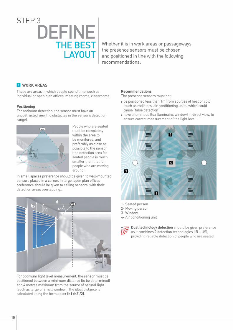
Whether it is in work areas or passageways, the presence sensors must be chosen and positioned in line with the following recommendations:
1 WORK AREASThese are areas in which people spend time, such as individual or open plan offices, meeting rooms, classrooms.
DEFINE THE BEST
LAYOUT
PositioningFor optimum detection, the sensor must have an unobstructed view (no obstacles in the sensor’s detection range).
People who are seated must be completely within the area to be monitored, and preferably as close as possible to the sensor (the detection area for seated people is much smaller than that for people who are moving around).
Recommendations The presence sensors must not: be positioned less than 1m from sources of heat or cold (such as radiators, air conditioning units) which could cause “false detection”
have a luminous flux (luminaire, window) in direct view, to ensure correct measurement of the light level.
In small spaces preference should be given to wall-mounted sensors placed in a corner. In large, open plan offices preference should be given to ceiling sensors (with their detection areas overlapping).
1- Seated person 2- Moving person 3- Window 4- Air conditioning unit
For optimum light level measurement, the sensor must be positioned between a minimum distance (to be determined) and 4 metres maximum from the source of natural light (such as large or small window). The ideal distance is calculated using the formula d= (h1+h2)/2).
Dual technology detection should be given preference as it combines 2 detection technologies (IR + US), providing reliable detection of people who are seated.
11DESIGN AND APPLICATION GUIDELIGHTING MANAGEMENT SENSORS
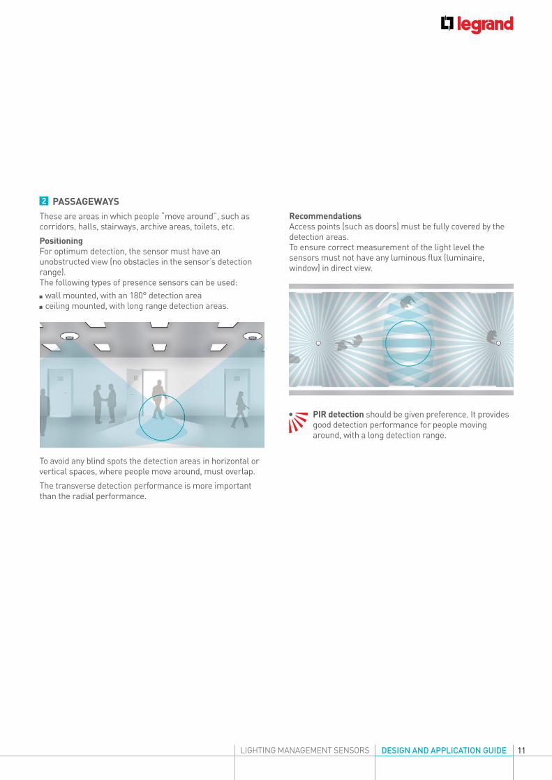
2 PASSAGEWAYSThese are areas in which people “move around”, such as corridors, halls, stairways, archive areas, toilets, etc.
PositioningFor optimum detection, the sensor must have an unobstructed view (no obstacles in the sensor’s detection range).The following types of presence sensors can be used: wall mounted, with an 180° detection area ceiling mounted, with long range detection areas.
Recommendations Access points (such as doors) must be fully covered by the detection areas.To ensure correct measurement of the light level the sensors must not have any luminous flux (luminaire, window) in direct view.
PIR detection should be given preference. It provides good detection performance for people moving around, with a long detection range.
To avoid any blind spots the detection areas in horizontal or vertical spaces, where people move around, must overlap.
The transverse detection performance is more important than the radial performance.
12
4 DIFFERENT OPERATING MODES
Occupancy (Auto on/Auto off mode)Automatic switch-on: detection of presence if there is an insufficient
natural level of light. Automatic switch-off: if no presence is detected and at the end of the time delay set if there is a sufficient level of natural light (activated light regulation).
Any new detection causes an automatic switch-on if there is insufficient light.
Walk through If there is no presence detected in the 20 seconds following an initial detection, the sensor will switch off after 3 minutes.
If a new presence is detected in the 3 minutes following the initial detection, the device will switch off at the end of the time delay set.
Vacancy (Manual on/Auto off mode) Manual switch-on, automatic switch-off: where no presence is detected and at the end of
the time delay set. Following switch-off, any new detection within a 30 second period will cause the device to be switched on automatically. After 30 seconds, the device is switched on via a manual switch.
Partial on/Group off modeThis mode is used to ungroup circuits that are switched on through detection and switched off at the end of detection. Example: on detection the main lighting is switched on and occasional lighting can be controlled manually at the same time. At the end of detection, the sensor orders the main lighting and the occasional lighting circuits to be switched off.
STEP 4
Daylight setpointValue at which the load comes on if light level is below the light setting and goes off if it is above
this threshold. The Daylight setpoint can be set up to a maximum of 1275 lux.Recommendation:passageway and corridors: 100 luxstairways: 150 luxoffices: 300 - 500 lux.
CalibrationIn order to set this calibration, it is necessary to measure the surrounding light level using
a luxmeter beforehand. The surrounding light level measured must then be transmitted to the sensor.
Steps for regulating the electric light factor: switch the light on and close the blinds wait 2 minutes measure the light level below the cell using a luxmeter.
Enter this value in the tool and send it to the cell. This calibration will be acknowledged during the next detection cycle.
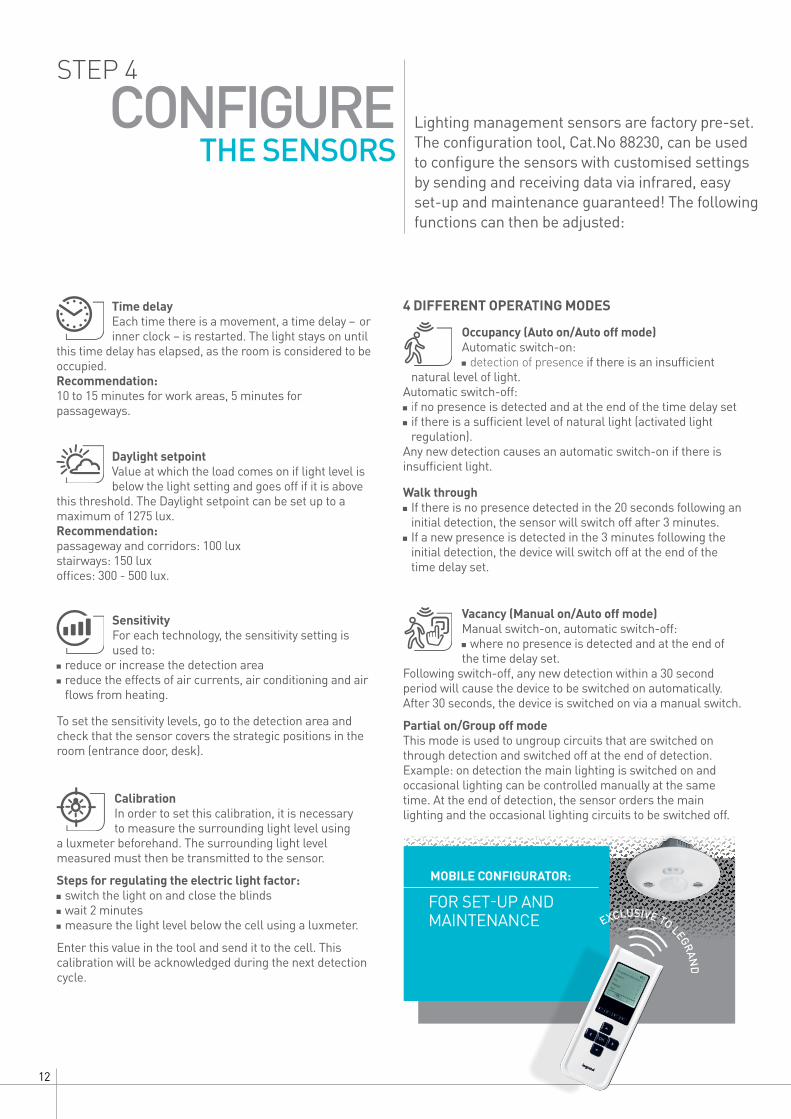
Lighting management sensors are factory pre-set. The configuration tool, Cat.No 88230, can be used to configure the sensors with customised settings by sending and receiving data via infrared, easy set-up and maintenance guaranteed! The following functions can then be adjusted:
CONFIGURE THE SENSORS
Time delayEach time there is a movement, a time delay – or inner clock – is restarted. The light stays on until
this time delay has elapsed, as the room is considered to be occupied.Recommendation:10 to 15 minutes for work areas, 5 minutes for passageways.
SensitivityFor each technology, the sensitivity setting is used to:
reduce or increase the detection area reduce the effects of air currents, air conditioning and air flows from heating.
To set the sensitivity levels, go to the detection area and check that the sensor covers the strategic positions in the room (entrance door, desk).
FOR SET-UP AND MAINTENANCE
MOBILE CONFIGURATOR:

13DESIGN AND APPLICATION GUIDELIGHTING MANAGEMENT SENSORS
APPLICATION EXAMPLES
FOR SPECIFIC BUILDING SPACES
OR
14
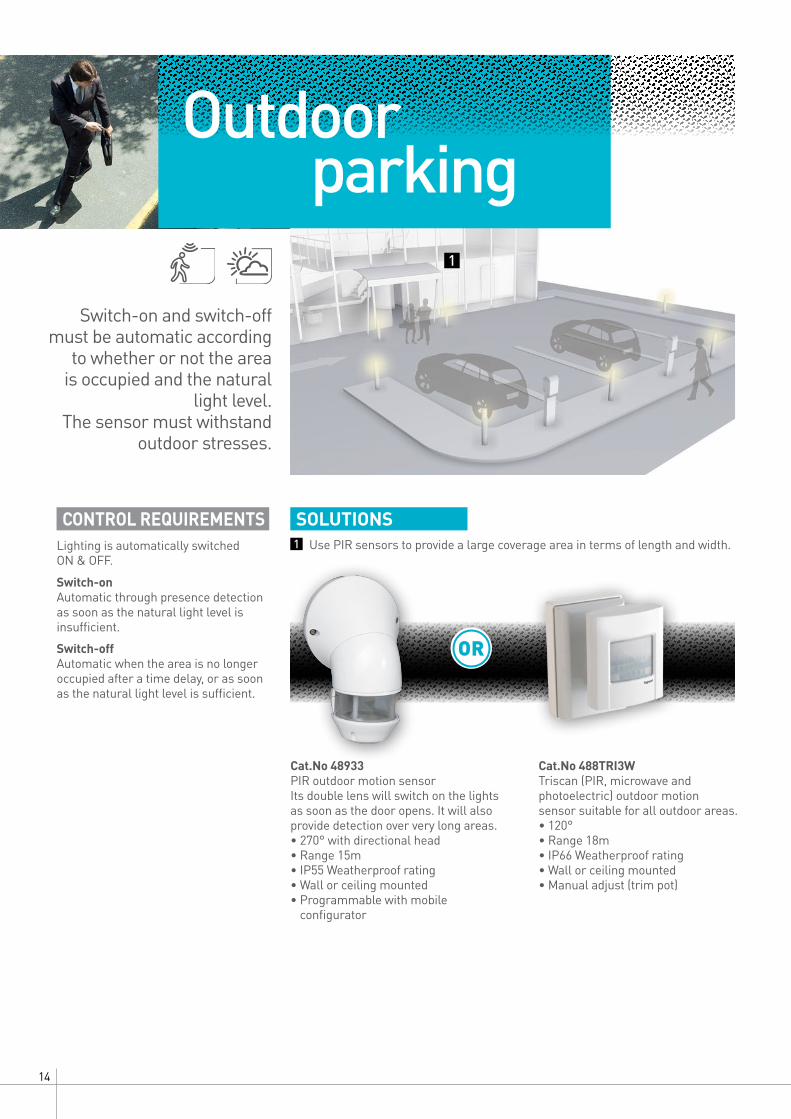
SOLUTIONSUse PIR sensors to provide a large coverage area in terms of length and width.
Cat.No 48933PIR outdoor motion sensor Its double lens will switch on the lights as soon as the door opens. It will also provide detection over very long areas. • 270° with directional head • Range 15m• IP55 Weatherproof rating• Wall or ceiling mounted• Programmable with mobile
configurator
Cat.No 488TRI3WTriscan (PIR, microwave and photoelectric) outdoor motion sensor suitable for all outdoor areas. • 120°• Range 18m• IP66 Weatherproof rating• Wall or ceiling mounted• Manual adjust (trim pot)
Outdoor parking
CONTROL REQUIREMENTSLighting is automatically switched ON & OFF.
1
1
Switch-on and switch-off must be automatic according
to whether or not the area is occupied and the natural
light level.The sensor must withstand
outdoor stresses.
Switch-on Automatic through presence detection as soon as the natural light level is insufficient.
Switch-off Automatic when the area is no longer occupied after a time delay, or as soon as the natural light level is sufficient.
15DESIGN AND APPLICATION GUIDELIGHTING MANAGEMENT SENSORS
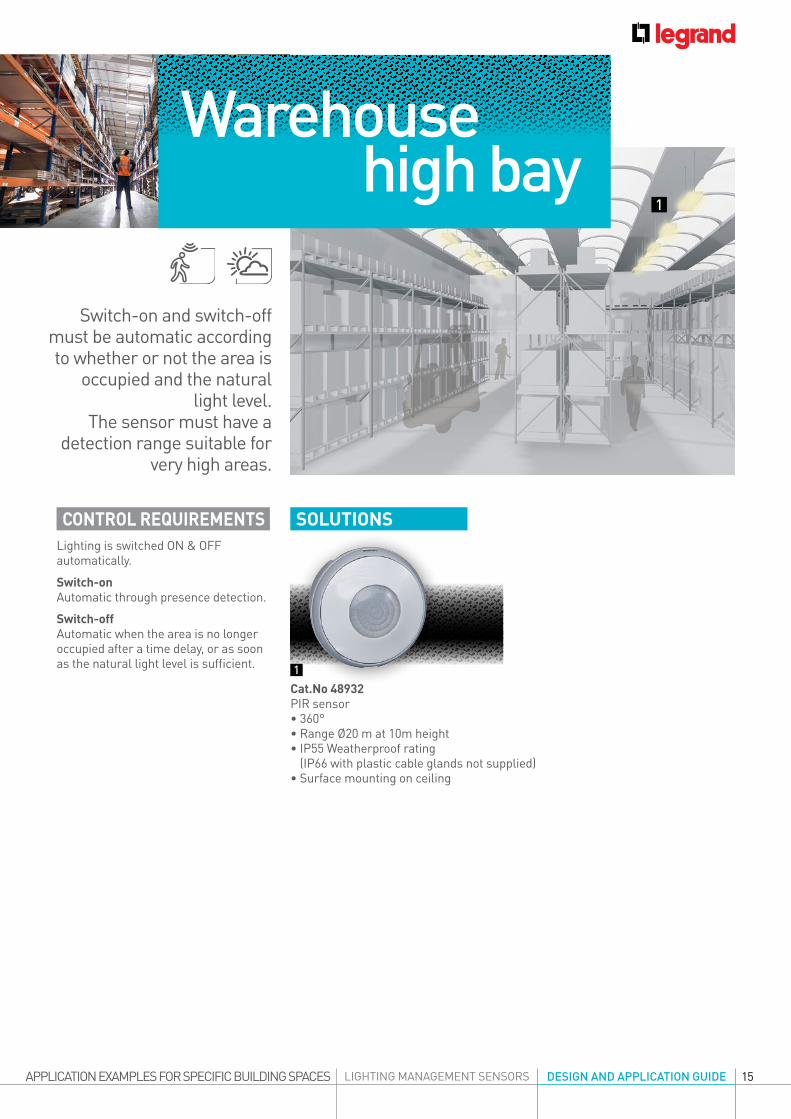
CONTROL REQUIREMENTSLighting is switched ON & OFF automatically.
SOLUTIONS
Cat.No 48932PIR sensor• 360° • Range Ø20 m at 10m height• IP55 Weatherproof rating
(IP66 with plastic cable glands not supplied)• Surface mounting on ceiling
Warehouse high bay
APPLICATION EXAMPLES FOR SPECIFIC BUILDING SPACES
1
1
Switch-on and switch-off must be automatic according to whether or not the area is
occupied and the natural light level.
The sensor must have a detection range suitable for
very high areas.
Switch-on Automatic through presence detection.
Switch-off Automatic when the area is no longer occupied after a time delay, or as soon as the natural light level is sufficient.
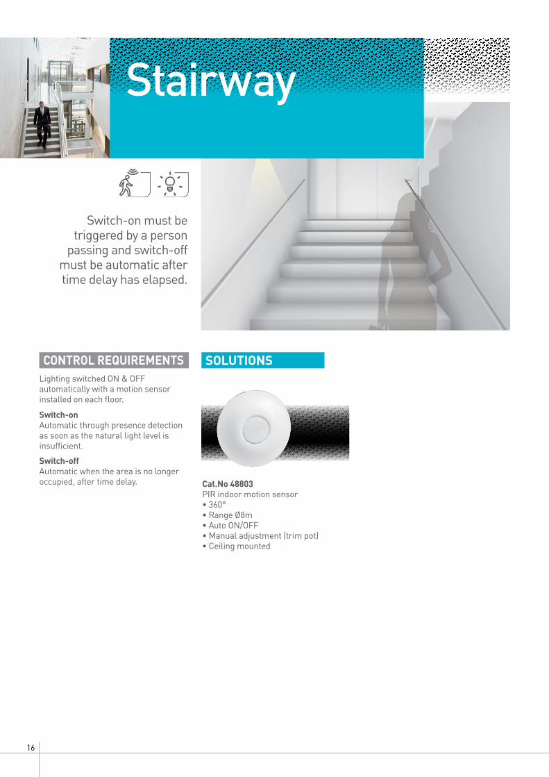
Cat.No 48803PIR indoor motion sensor • 360° • Range Ø8m• Auto ON/OFF• Manual adjustment (trim pot)• Ceiling mounted
16
SOLUTIONS
Stairway
CONTROL REQUIREMENTSLighting switched ON & OFF automatically with a motion sensor installed on each floor.
Switch-on Automatic through presence detection as soon as the natural light level is insufficient.
Switch-off Automatic when the area is no longer occupied, after time delay.
Switch-on must be triggered by a person
passing and switch-off must be automatic after time delay has elapsed.
17DESIGN AND APPLICATION GUIDELIGHTING MANAGEMENT SENSORS
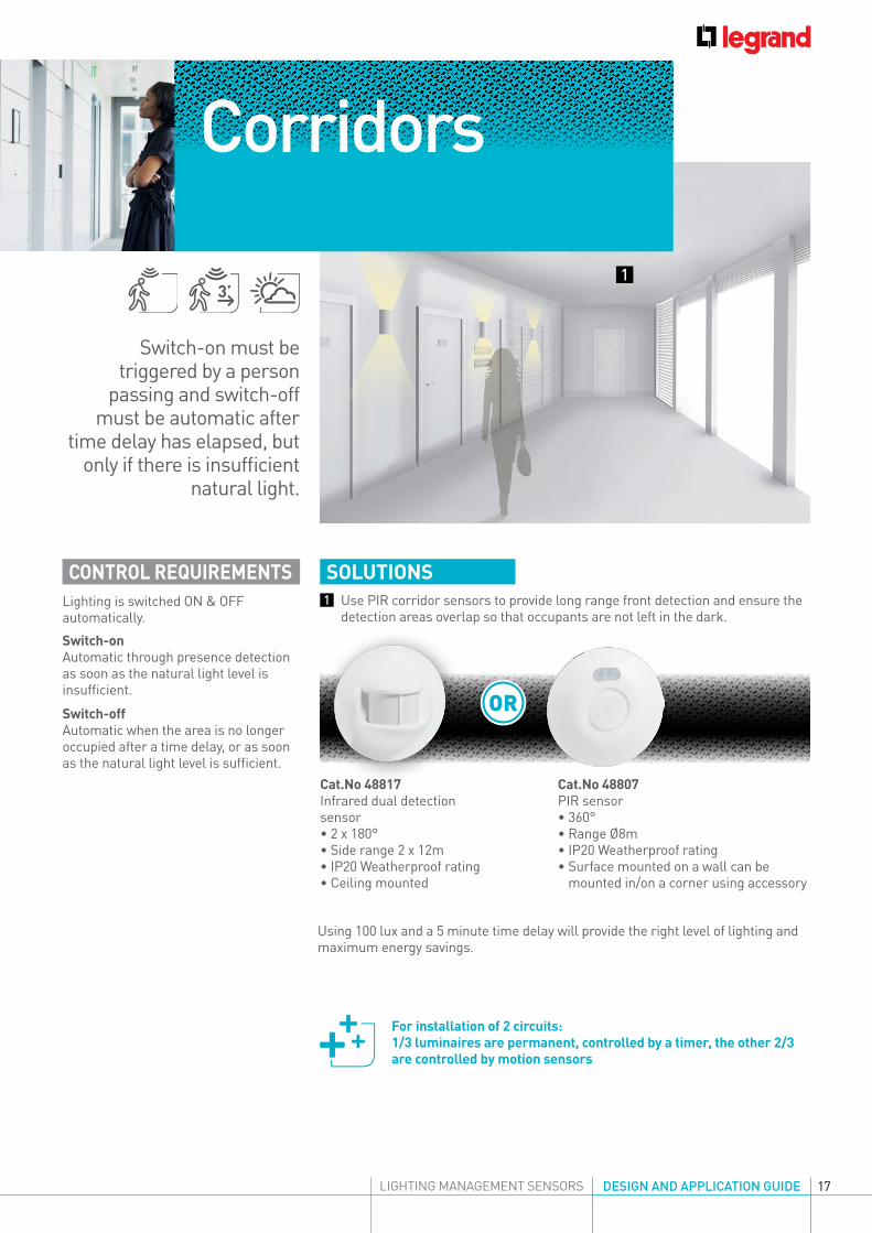
Use PIR corridor sensors to provide long range front detection and ensure the detection areas overlap so that occupants are not left in the dark.
CONTROL REQUIREMENTSLighting is switched ON & OFF automatically.
SOLUTIONS
Cat.No 48817Infrared dual detectionsensor• 2 x 180°• Side range 2 x 12m• IP20 Weatherproof rating• Ceiling mounted
Cat.No 48807PIR sensor • 360°• Range Ø8m• IP20 Weatherproof rating• Surface mounted on a wall can be
mounted in/on a corner using accessory
Corridors
Using 100 lux and a 5 minute time delay will provide the right level of lighting and maximum energy savings.
OR
1
1
For installation of 2 circuits: 1/3 luminaires are permanent, controlled by a timer, the other 2/3 are controlled by motion sensors
Switch-on must be triggered by a person
passing and switch-off must be automatic after
time delay has elapsed, but only if there is insufficient
natural light.
Switch-on Automatic through presence detection as soon as the natural light level is insufficient.
Switch-off Automatic when the area is no longer occupied after a time delay, or as soon as the natural light level is sufficient.
18
SOLUTIONS
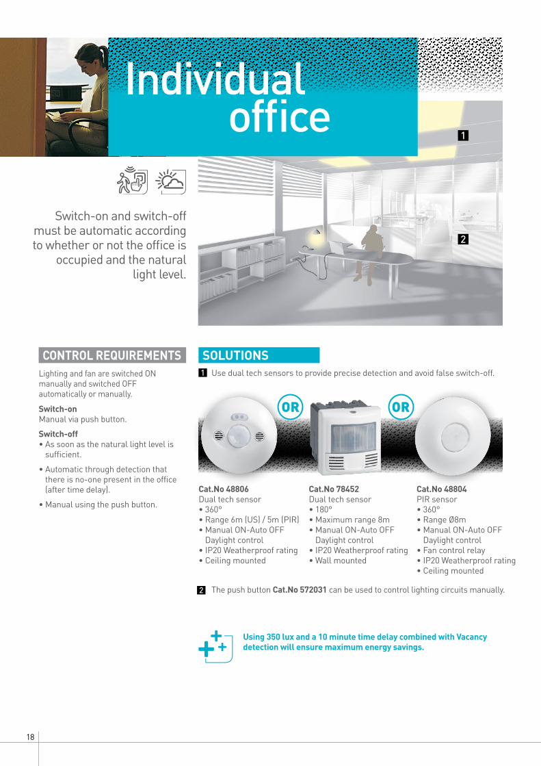
The push button Cat.No 572031 can be used to control lighting circuits manually.
Use dual tech sensors to provide precise detection and avoid false switch-off.
Cat.No 48806Dual tech sensor• 360°• Range 6m (US) / 5m (PIR)• Manual ON-Auto OFF
Daylight control • IP20 Weatherproof rating• Ceiling mounted
Cat.No 78452Dual tech sensor• 180°• Maximum range 8m• Manual ON-Auto OFF
Daylight control• IP20 Weatherproof rating• Wall mounted
Cat.No 48804PIR sensor• 360°• Range Ø8m• Manual ON-Auto OFF
Daylight control • Fan control relay• IP20 Weatherproof rating• Ceiling mounted
OR OR
Individual office
Using 350 lux and a 10 minute time delay combined with Vacancy detection will ensure maximum energy savings.
CONTROL REQUIREMENTSLighting and fan are switched ON manually and switched OFF automatically or manually.
1
2
1
2
Switch-on and switch-off must be automatic according to whether or not the office is
occupied and the natural light level.
Switch-on Manual via push button.
Switch-off • As soon as the natural light level is
sufficient.
• Automatic through detection that there is no-one present in the office (after time delay).
• Manual using the push button.

19DESIGN AND APPLICATION GUIDELIGHTING MANAGEMENT SENSORS
CONTROL REQUIREMENTSLighting is switched ON manually and switched OFF automatically or manually.
SOLUTIONS
Cat.No 48822Dual tech occupancy sensor• Range 6m (US) / 5m (PIR)• IP20 Weatherproof rating• Ceiling mounted
Cat.No 48844Room controller for DALI and DSI dimming • Occupancy mode, vacancy mode. • The room controller applies a
dimming difference of 30, 50 or 80% between the window and the corridor side.
• Fixed directly to the false ceiling via cable ducting.
The push button Cat.No 572031 can be used to control lighting circuits manually.
Classroom3
1 2
1
2
3
3The lighting is dependent on whether the areas are
occupied and on differences in the natural light level in
the classroom.An additional manual
control can be used to dim the lighting.
Switch-on Manual via push button for the room and the board.
Switch-off • As soon as the natural light level is
sufficient.
• Automatic when the area in the classroom is no longer occupied, after a time delay. Automatic switch-off of the board lighting is linked to the classroom lighting.
• Manual using the push button.
Lighting regulation The amount of artificial lighting is adapted according to the natural light, so that a minimum lighting level is constantly maintained.
Note: users can adjust the light level to their own requirements using the push button. Automatic management will take over again when the user is absent.
The area on the window side will thus have a lower level of artificial light than that on the opposite side.
20
SOLUTIONS
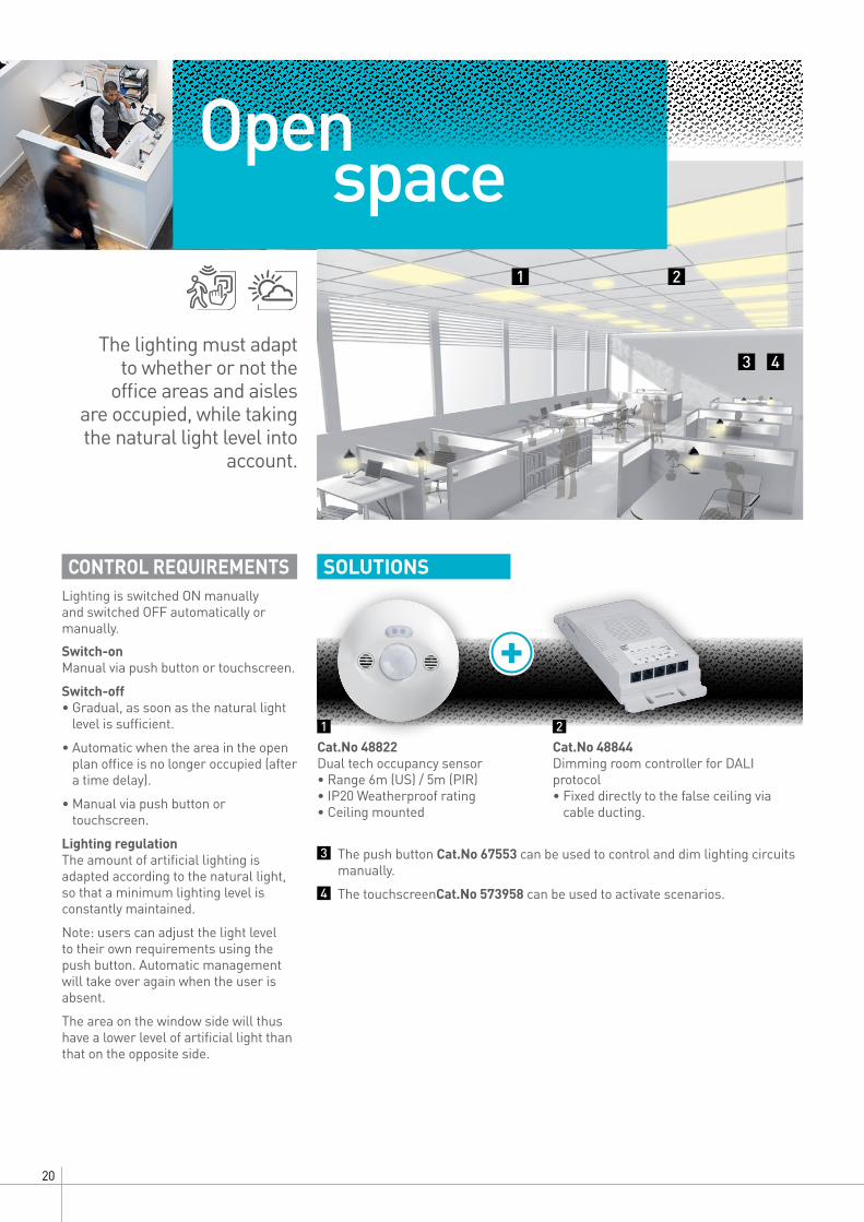
The push button Cat.No 67553 can be used to control and dim lighting circuits manually.
The touchscreenCat.No 573958 can be used to activate scenarios.
Open space
CONTROL REQUIREMENTSLighting is switched ON manually and switched OFF automatically or manually.
Cat.No 48822Dual tech occupancy sensor• Range 6m (US) / 5m (PIR)• IP20 Weatherproof rating• Ceiling mounted
Cat.No 48844Dimming room controller for DALI protocol • Fixed directly to the false ceiling via
cable ducting.
1 2
1 2
3
4
3 4The lighting must adapt
to whether or not the office areas and aisles
are occupied, while taking the natural light level into
account.
Switch-on Manual via push button or touchscreen.
Switch-off • Gradual, as soon as the natural light
level is sufficient.
• Automatic when the area in the open plan office is no longer occupied (after a time delay).
• Manual via push button or touchscreen.
Lighting regulation The amount of artificial lighting is adapted according to the natural light, so that a minimum lighting level is constantly maintained.
Note: users can adjust the light level to their own requirements using the push button. Automatic management will take over again when the user is absent.
The area on the window side will thus have a lower level of artificial light than that on the opposite side.
21DESIGN AND APPLICATION GUIDELIGHTING MANAGEMENT SENSORS
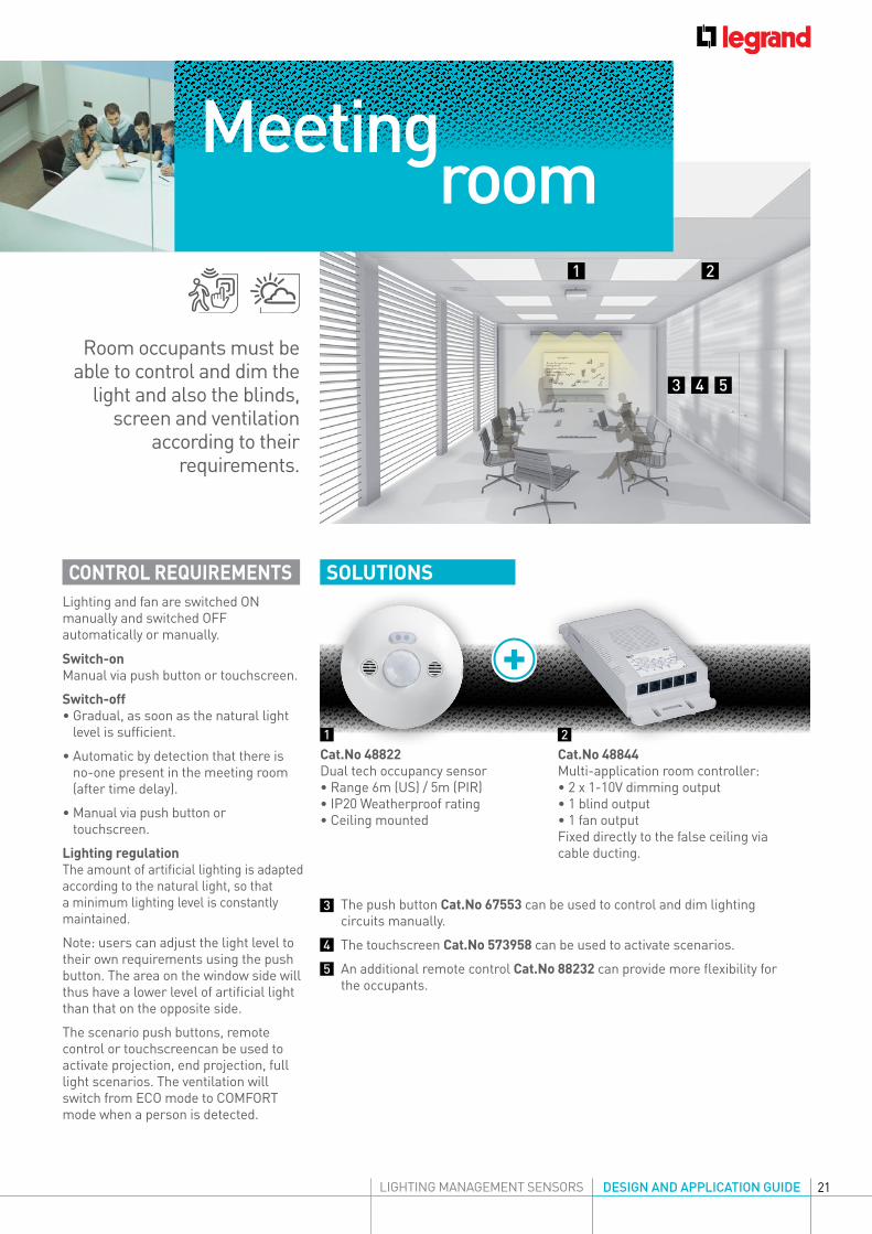
CONTROL REQUIREMENTSLighting and fan are switched ON manually and switched OFF automatically or manually.
SOLUTIONS
Cat.No 48822Dual tech occupancy sensor• Range 6m (US) / 5m (PIR)• IP20 Weatherproof rating• Ceiling mounted
Cat.No 48844Multi-application room controller: • 2 x 1-10V dimming output• 1 blind output• 1 fan outputFixed directly to the false ceiling via cable ducting.
The push button Cat.No 67553 can be used to control and dim lighting circuits manually.
The touchscreen Cat.No 573958 can be used to activate scenarios.
An additional remote control Cat.No 88232 can provide more flexibility for the occupants.
1 2
1 2
3 4 5
3
4
5
Meeting room
Room occupants must be able to control and dim the
light and also the blinds, screen and ventilation
according to their requirements.
Switch-on Manual via push button or touchscreen.
Switch-off • Gradual, as soon as the natural light
level is sufficient.
• Automatic by detection that there is no-one present in the meeting room (after time delay).
• Manual via push button or touchscreen.
Lighting regulation The amount of artificial lighting is adapted according to the natural light, so that a minimum lighting level is constantly maintained.
Note: users can adjust the light level to their own requirements using the push button. The area on the window side will thus have a lower level of artificial light than that on the opposite side.
The scenario push buttons, remote control or touchscreencan be used to activate projection, end projection, full light scenarios. The ventilation will switch from ECO mode to COMFORT mode when a person is detected.
22
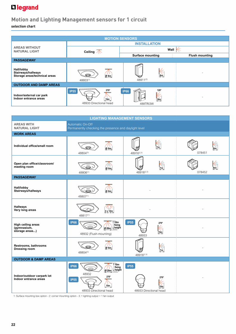
Motion and Lighting Management sensors for 1 circuitselection chart
LIGHTING MANAGEMENT SENSORS
AREAS WITH NATURAL LIGHT
WORK AREAS
Individual office/small roomØ 8m
48804(3)
8m
078451
Open plan office/classroom/meeting room
Ø 6m
48806(1)
7m
48916(2,3)
8m
078452
PASSAGEWAY
Hall/lobbyStairways/hallways Ø 8m
48807(1)
- -
HallwaysVery long areas 2 x 12m
48817(1)
- -
High ceiling areas (gymnasium,storage areas...) 15m
270°
48933
-
Restrooms, bathroomsDressing room Ø 8m
48804(3)7m
48916(2,3)
-
OUTDOOR & DAMP AREAS
Indoor/outdoor carpark lotIndoor entrance areas
15m
270°
48933 Directional head
-
PASSAGEWAY
Hall/lobbyStairways/hallwaysStorage areas/technical areas Ø 8m
48803(1)
8m
48911(2)
-
OUTDOOR AND DAMP AREAS
Indoor/external car parkIndoor entrance areas -
Automatic On-Off Permanently checking the presence and daylight level
MOTION SENSORS
AREAS WITHOUT NATURAL LIGHT
INSTALLATION
Ceiling Wall
Surface mounting Flush mounting
1: Surface mounting box option - 2: corner mounting option - 3: 1 lighting output + 1 fan output
IP66
IP66 IP55
IP55
IP55
IP66IP55
48916(2,3)
488TRI3W
7m
Ø 20m
10mfixingheight
48932
18m
120°
15m
270°
48933 Directional head
Ø 20m
10mfixingheight
48932 (Flush-mounting)
48933 Directional head
15m
270°
23
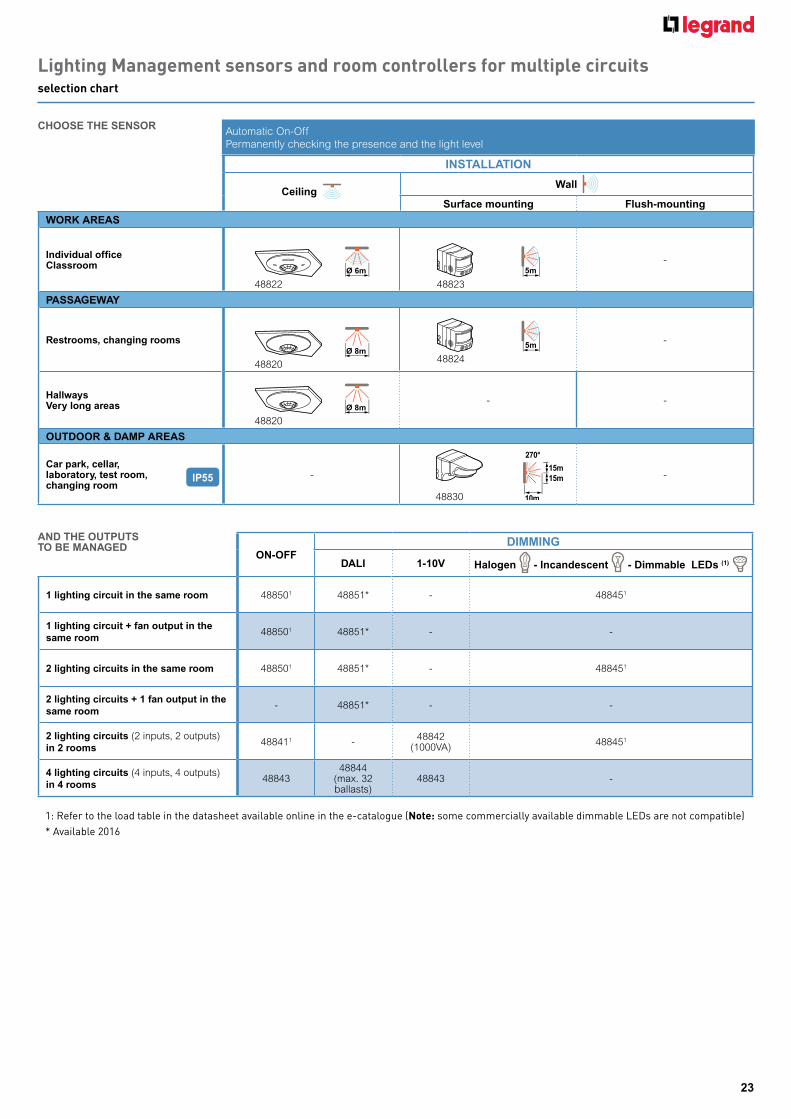
Lighting Management sensors and room controllers for multiple circuitsselection chart
WORK AREAS
Individual officeClassroom
Ø 6m
48822
5m
48823
-
PASSAGEWAY
Restrooms, changing roomsØ 8m
48820
-
HallwaysVery long areas Ø 8m
48820
- -
OUTDOOR & DAMP AREAS
Car park, cellar, laboratory, test room, changing room
-
10m
15m15m
270°
48830
-
ON-OFFDIMMING
DALI 1-10V Halogen - Incandescent - Dimmable LEDs (1)
1 lighting circuit in the same room 488501 48851* - 488451
1 lighting circuit + fan output in the same room
488501 48851* - -
2 lighting circuits in the same room 488501 48851* - 488451
2 lighting circuits + 1 fan output in the same room
- 48851* - -
2 lighting circuits (2 inputs, 2 outputs) in 2 rooms
488411 - 48842 (1000VA) 488451
4 lighting circuits (4 inputs, 4 outputs) in 4 rooms
4884348844
(max. 32 ballasts)
48843 -
1: Refer to the load table in the datasheet available online in the e-catalogue (Note: some commercially available dimmable LEDs are not compatible)* Available 2016
Automatic On-Off Permanently checking the presence and the light level
INSTALLATION
Ceiling Wall
Surface mounting Flush-mounting
CHOOSE THE SENSOR
AND THE OUTPUTSTO BE MANAGED
IP55
5m
48824
24
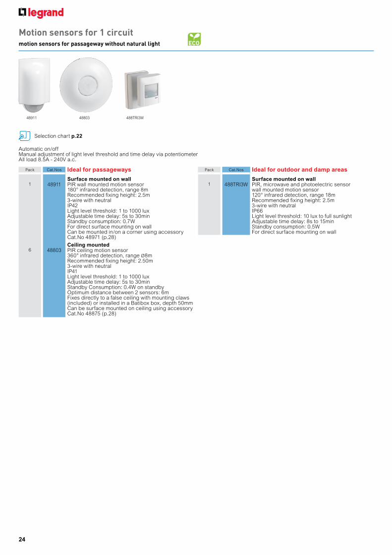
Automatic on/offManual adjustment of light level threshold and time delay via potentiometerAll load 8.5A - 240V a.c.
Pack Cat.Nos Ideal for passageways
Surface mounted on wall1 48911 PIR wall mounted motion sensor
180° infrared detection, range 8mRecommended fixing height: 2.5m3-wire with neutralIP42Light level threshold: 1 to 1000 luxAdjustable time delay: 5s to 30minStandby consumption: 0.7WFor direct surface mounting on wallCan be mounted in/on a corner using accessory Cat.No 48971 (p.28)
Ceiling mounted6 48803 PIR ceiling motion sensor
360° infrared detection, range Ø8mRecommended fixing height: 2.50m3-wire with neutralIP41Light level threshold: 1 to 1000 luxAdjustable time delay: 5s to 30minStandby Consumption: 0.4W on standbyOptimum distance between 2 sensors: 6mFixes directly to a false ceiling with mounting claws (included) or installed in a Batibox box, depth 50mmCan be surface mounted on ceiling using accessory Cat.No 48875 (p.28)
Pack Cat.Nos Ideal for outdoor and damp areas
Surface mounted on wall1 488TRI3W PIR, microwave and photoelectric sensor
wall mounted motion sensor120° infrared detection, range 18mRecommended fixing height: 2.5m3-wire with neutralIP66Light level threshold: 10 lux to full sunlightAdjustable time delay: 8s to 15minStandby consumption: 0.5WFor direct surface mounting on wall
488TRI3W4880348911
Motion sensors for 1 circuitmotion sensors for passageway without natural light
Selection chart p.22
25
5m
5m
3m
18m
1.5m3m
10m
1.2m
1.5m
1.3m
0.5m
3m
1.5m
3m
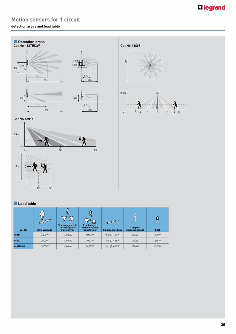
n Detection areasCat.No 488TRI3W Cat.No 48803
Cat.No 48911
8m
2.4m
45 2 1 0 1 2 4 5m:
Cat.No Halogen bulb
ELV halogen with ferromagnetic transformer
ELV halogen with electronic
transformer Fluorescent tubeCompact
fluorescent bulb LED
48911 2000W 1000VA 1000VA 10 x (2 x 36W) 250W 250W
48803 2000W 1000VA 1000VA 10 x (2 x 36W) 250W 250W
488TRI3W 2000W 2400VA 2400VA 10 x (2 x 36W) 2400W 1200W
n Load table
Motion sensors for 1 circuitdetection areas and load table
6m
8m4m
2.5m
4m 8m0

26
Lighting Management sensors for 1 circuitLighting Management sensors for passageway with natural light
Check presence and natural light level continuously, switch off when there is sufficient natural lightOccupancy mode (automatic switch-on/off factory setting). Can be used with push button Cat.No 572030 (or illuminated push button Cat.No 572032) for vacancy mode (manual switch-on and manual or automatic switch-off). Precise on-site adjustment using configuration tool Cat.No 88230(p.28)Adjustable time delay: 5s to 59min. Light level threshold adjustable from 5 to 1275 lux
Pack Cat.Nos Ideal for passageways
Ceiling mountedFix directly to a false ceiling with mounting claws (included) or installed in a Batibox box, depth 50mm, Cat.No 800513 wire with neutralStandby consumption: 0.4WRecommended fixing height: 2.5m
1 48817 PIR ceiling mounted Lighting Management sensors360° infrared with detection angle of 2 x 12mIdeal for hallwayIP20Optimum distance between 2 sensors: 20mConnection via automatic terminalsSurface mounted on ceiling using accessoryCat.No 48875 (p.28)
1 48807 PIR ceiling mounted Lighting Management sensors360° infrared detection, range Ø8mOptimum distance between 2 sensors: 6mConnection via automatic terminalsSurface mounted on ceiling using accessoryCat.No 48875 (p.28)
Pack Cat.Nos Ideal for outdoor and damp areas
Wall or ceiling mounted1 48933 PIR wall and ceiling mounted multi lens Lighting
Management sensors270° infrared detection with directional head,range 15mRecommended fixing height: 2.5m3 wire with neutralIP55Standby consumption: 0.7W
Ideal for high ceiling areasCeiling mounted
1 48932 PIR ceiling mounted Lighting Management sensors360° infrared detection, Ø20m at 10m high, Ø8m at 2.5m high3-wire with neutralIP55, IP66 with cable gland Cat.No 098003Optimum distance between 2 sensors: 20mStandby consumption: 0.4WCompatible with Cablofil cable trays
Selection chart p.22Load table p.29
48817 48807
With knock-out cable entries
48933 48932
27
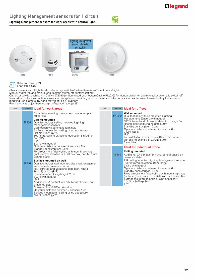
Lighting Management sensors for 1 circuitLighting Management sensors for work areas with natural light
Check presence and light level continuously, switch off when there is sufficient natural light Manual switch-on and manual or automatic switch-off (factory setting)Can be used with push button Cat.No 572030 (or illuminated push button Cat.No 572032) for manual switch-on and manual or automatic switch-offInfrared and ultrasonic motion sensors for workplaces, providing precise presence detection as soon as the wave transmitted by the sensor is modified (for example, by hand movement on a keyboard)Precise on-site adjustment using configuration tool (p.28)
Pack Cat.Nos Ideal for work areas
Suitable for meeting room, classroom, open plan office, etc.
Ceiling mounted1 48806 Dual technology ceiling mounted Lighting
Management sensorsConnection via automatic terminalsSurface mounted on ceiling using accessoryCat.No 48875 (p.28)360° infrared and ultrasonic detection, 6m(US) or 5m(PIR)IP203 wire with neutralOptimum distance between 2 sensors: 6mStandby consumption: 0.8WFix directly to a false ceiling with mounting claws(included) or installed in a Batibox box, depth 50mm Cat.No 80051
Surface mounted on wall1 48916 Dual technology wall mounted Lighting Management
sensors with presence output180° infrared and ultrasonic detection, range 7m(US) or 12m(PIR)Recommended fixing height: 2.5m3 wire with neutralIP42Additional 2A contact for HVAC control based on presence dataConsumption: 0.4W on standbyOptimum distance between 2 sensors: 10mSurface mounted on ceiling using accessoryCat.No 48971 (p.28)
Pack Cat.Nos Ideal for offices
Wall mounted1 078452 Dual technology flush mounted Lighting
Management sensors with neutral180° infrared and ultrasonic detection, range 8mRecommended fixing height: 1.20mStandby consumption: 0.2WOptimum distance between 2 sensors: 6m3 wire cableIP20For installation in box, depth 40mm min., or in surface mounting box Cat.No 800512 modules
Ideal for individual officeCeiling mounted
1 48804 Additional 2A contact for HVAC control based on presence dataPIR ceiling mounted Lighting Management sensors 360° infrared detection, Ø8m range3 wire with neutralOptimum distance between 2 sensors: 6mStandby consumption: 0.4WFixes directly to a false ceiling with mounting claws (included) or installed in a Batibox box, depth 50mmSurface mounted on ceiling using accessoryCat.No 48875 (p.28)IP20
Selection chart p.22Load table p.29
07845248806 48916 48804
Lighting Management sensor: Integrated
pushbutton
28
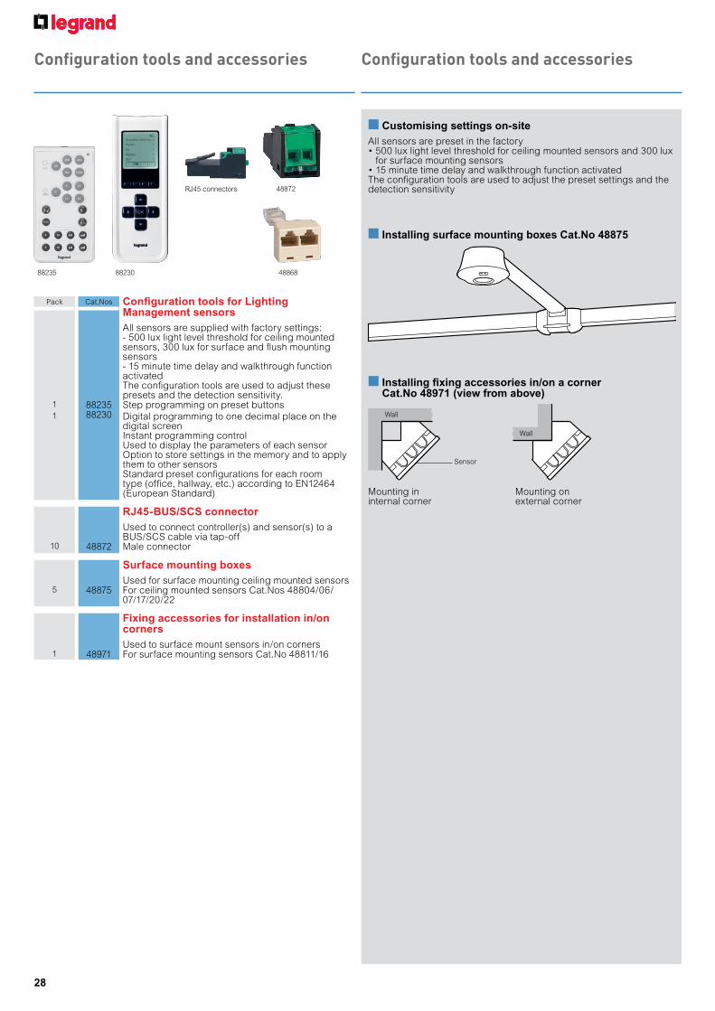
Configuration tools and accessoriesConfiguration tools and accessories
Pack Cat.Nos Configuration tools for Lighting Management sensorsAll sensors are supplied with factory settings:- 500 lux light level threshold for ceiling mounted sensors, 300 lux for surface and flush mounting sensors- 15 minute time delay and walkthrough function activatedThe configuration tools are used to adjust these presets and the detection sensitivity.
1 88235 Step programming on preset buttons1 88230 Digital programming to one decimal place on the
digital screenInstant programming control Used to display the parameters of each sensor Option to store settings in the memory and to apply them to other sensors Standard preset configurations for each room type (office, hallway, etc.) according to EN12464 (European Standard)
RJ45-BUS/SCS connectorUsed to connect controller(s) and sensor(s) to a BUS/SCS cable via tap-off
10 48872 Male connector
Surface mounting boxesUsed for surface mounting ceiling mounted sensors
5 48875 For ceiling mounted sensors Cat.Nos 48804/06/07/17/20/22
Fixing accessories for installation in/on cornersUsed to surface mount sensors in/on corners
1 48971 For surface mounting sensors Cat.No 48811/16
88235 88230
48872
48868
RJ45 connectors
n Customising settings on-siteAll sensors are preset in the factory • 500 lux light level threshold for ceiling mounted sensors and 300 lux
for surface mounting sensors• 15 minute time delay and walkthrough function activatedThe configuration tools are used to adjust the preset settings and the detection sensitivity
Mounting in internal corner
Mounting on external corner
n Installing surface mounting boxes Cat.No 48875
n Installing fixing accessories in/on a corner Cat.No 48971 (view from above)
Wall
Wall
Sensor
29
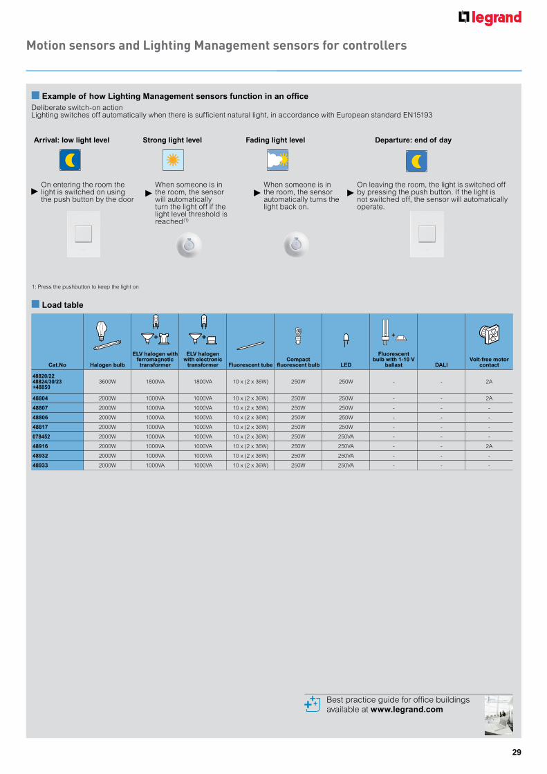
Motion sensors and Lighting Management sensors for controllers
n Example of how Lighting Management sensors function in an officeDeliberate switch-on actionLighting switches off automatically when there is sufficient natural light, in accordance with European standard EN15193
n Load table
Cat.No Halogen bulb
ELV halogen with ferromagnetic transformer
ELV halogen with electronic
transformer Fluorescent tubeCompact
fluorescent bulb LED
Fluorescent bulb with 1-10 V
ballast DALIVolt-free motor
contact
48820/2248824/30/23 +48850
3600W 1800VA 1800VA 10 x (2 x 36W) 250W 250W - - 2A
48804 2000W 1000VA 1000VA 10 x (2 x 36W) 250W 250W - - 2A
48807 2000W 1000VA 1000VA 10 x (2 x 36W) 250W 250W - - -
48806 2000W 1000VA 1000VA 10 x (2 x 36W) 250W 250W - - -
48817 2000W 1000VA 1000VA 10 x (2 x 36W) 250W 250W - - -
078452 2000W 1000VA 1000VA 10 x (2 x 36W) 250W 250VA - - -
48916 2000W 1000VA 1000VA 10 x (2 x 36W) 250W 250VA - - 2A
48932 2000W 1000VA 1000VA 10 x (2 x 36W) 250W 250VA - - -
48933 2000W 1000VA 1000VA 10 x (2 x 36W) 250W 250VA - - -
Arrival: low light level Strong light level Fading light level Departure: end of day
On entering the room the light is switched on using the push button by the door
When someone is in the room, the sensor will automatically turn the light off if the light level threshold is reached(1)
When someone is in the room, the sensor automatically turns the light back on.
On leaving the room, the light is switched off by pressing the push button. If the light is not switched off, the sensor will automatically operate.
1: Press the pushbutton to keep the light on
Best practice guide for office buildings available at www.legrand.com
30
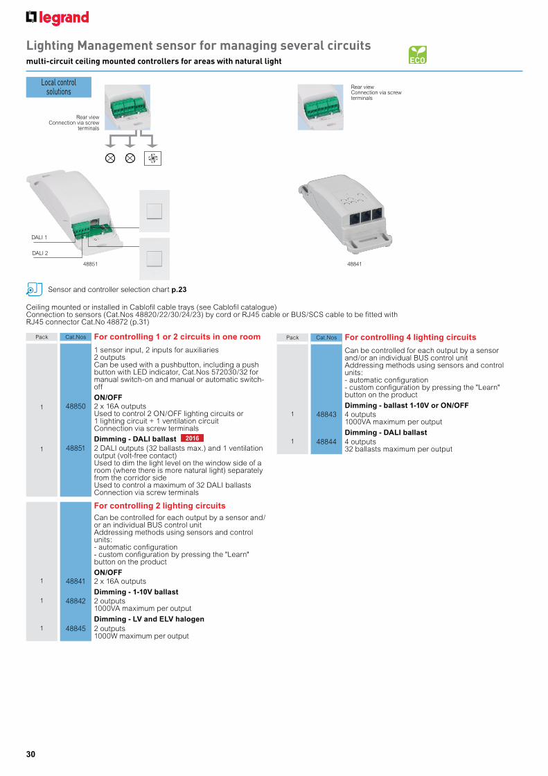
Lighting Management sensor for managing several circuitsmulti-circuit ceiling mounted controllers for areas with natural light
Ceiling mounted or installed in Cablofil cable trays (see Cablofil catalogue)Connection to sensors (Cat.Nos 48820/22/30/24/23) by cord or RJ45 cable or BUS/SCS cable to be fitted with RJ45 connector Cat.No 48872 (p.31)
Sensor and controller selection chart p.23
Rear view Connection via screw
terminals
48851
DALI 1
DALI 2
Local control solutions
Rear view Connection via screw terminals
48841
Pack Cat.Nos For controlling 1 or 2 circuits in one room
1 sensor input, 2 inputs for auxiliaries2 outputsCan be used with a pushbutton, including a push button with LED indicator, Cat.Nos 572030/32 for manual switch-on and manual or automatic switch-off
ON/OFF1 48850 2 x 16A outputs
Used to control 2 ON/OFF lighting circuits or 1 lighting circuit + 1 ventilation circuitConnection via screw terminals
Dimming - DALI ballast1 48851 2 DALI outputs (32 ballasts max.) and 1 ventilation
output (volt-free contact)Used to dim the light level on the window side of a room (where there is more natural light) separately from the corridor sideUsed to control a maximum of 32 DALI ballastsConnection via screw terminals
For controlling 2 lighting circuitsCan be controlled for each output by a sensor and/or an individual BUS control unitAddressing methods using sensors and control units:- automatic configuration- custom configuration by pressing the "Learn" button on the product
ON/OFF1 48841 2 x 16A outputs
Dimming - 1-10V ballast1 48842 2 outputs
1000VA maximum per output
Dimming - LV and ELV halogen1 48845 2 outputs
1000W maximum per output
Pack Cat.Nos For controlling 4 lighting circuits
Can be controlled for each output by a sensorand/or an individual BUS control unitAddressing methods using sensors and control units:- automatic configuration- custom configuration by pressing the "Learn" button on the product
Dimming - ballast 1-10V or ON/OFF1 48843 4 outputs
1000VA maximum per output
Dimming - DALI ballast1 48844 4 outputs
32 ballasts maximum per output
2016
31
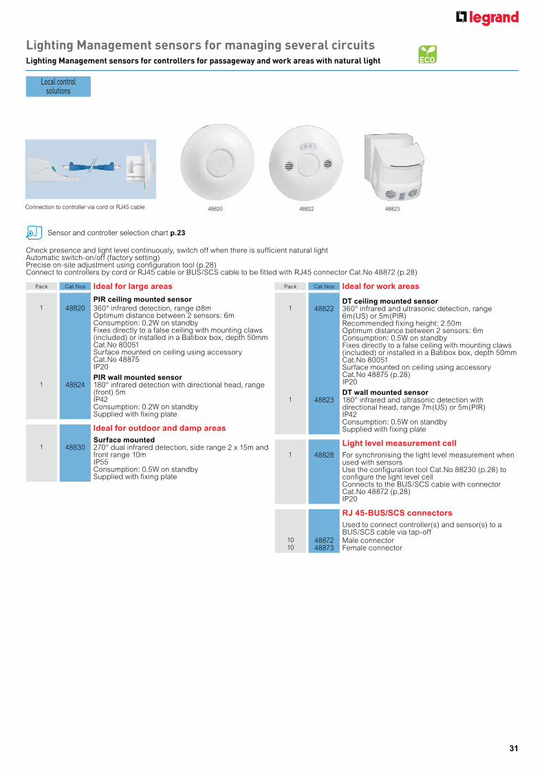
Lighting Management sensors for managing several circuitsLighting Management sensors for controllers for passageway and work areas with natural light
Check presence and light level continuously, switch off when there is sufficient natural lightAutomatic switch-on/off (factory setting)Precise on-site adjustment using configuration tool (p.28)Connect to controllers by cord or RJ45 cable or BUS/SCS cable to be fitted with RJ45 connector Cat.No 48872 (p.28)
Pack Cat.Nos Ideal for large areas
PIR ceiling mounted sensor1 48820 360° infrared detection, range Ø8m
Optimum distance between 2 sensors: 6mConsumption: 0.2W on standbyFixes directly to a false ceiling with mounting claws (included) or installed in a Batibox box, depth 50mm Cat.No 80051Surface mounted on ceiling using accessoryCat.No 48875IP20
PIR wall mounted sensor1 48824 180° infrared detection with directional head, range
(front) 5mIP42Consumption: 0.2W on standbySupplied with fixing plate
Ideal for outdoor and damp areasSurface mounted
1 48830 270° dual infrared detection, side range 2 x 15m and front range 10mIP55Consumption: 0.5W on standbySupplied with fixing plate
Sensor and controller selection chart p.23
Pack Cat.Nos Ideal for work areas
DT ceiling mounted sensor1 48822 360° infrared and ultrasonic detection, range
6m(US) or 5m(PIR)Recommended fixing height: 2.50mOptimum distance between 2 sensors: 6mConsumption: 0.5W on standbyFixes directly to a false ceiling with mounting claws (included) or installed in a Batibox box, depth 50mm Cat.No 80051Surface mounted on ceiling using accessoryCat.No 48875 (p.28)IP20
DT wall mounted sensor1 48823 180° infrared and ultrasonic detection with
directional head, range 7m(US) or 5m(PIR)IP42Consumption: 0.5W on standbySupplied with fixing plate
Light level measurement cell1 48828 For synchronising the light level measurement when
used with sensors Use the configuration tool Cat.No 88230 (p.28) to configure the light level cell Connects to the BUS/SCS cable with connectorCat.No 48872 (p.28) IP20
RJ 45-BUS/SCS connectorsUsed to connect controller(s) and sensor(s) to a BUS/SCS cable via tap-off
10 48872 Male connector10 48873 Female connector
Local control solutions
48823Connection to controller via cord or RJ45 cable 4882248820
Sensor and controller selection chart Technical characteristics e-catalogue
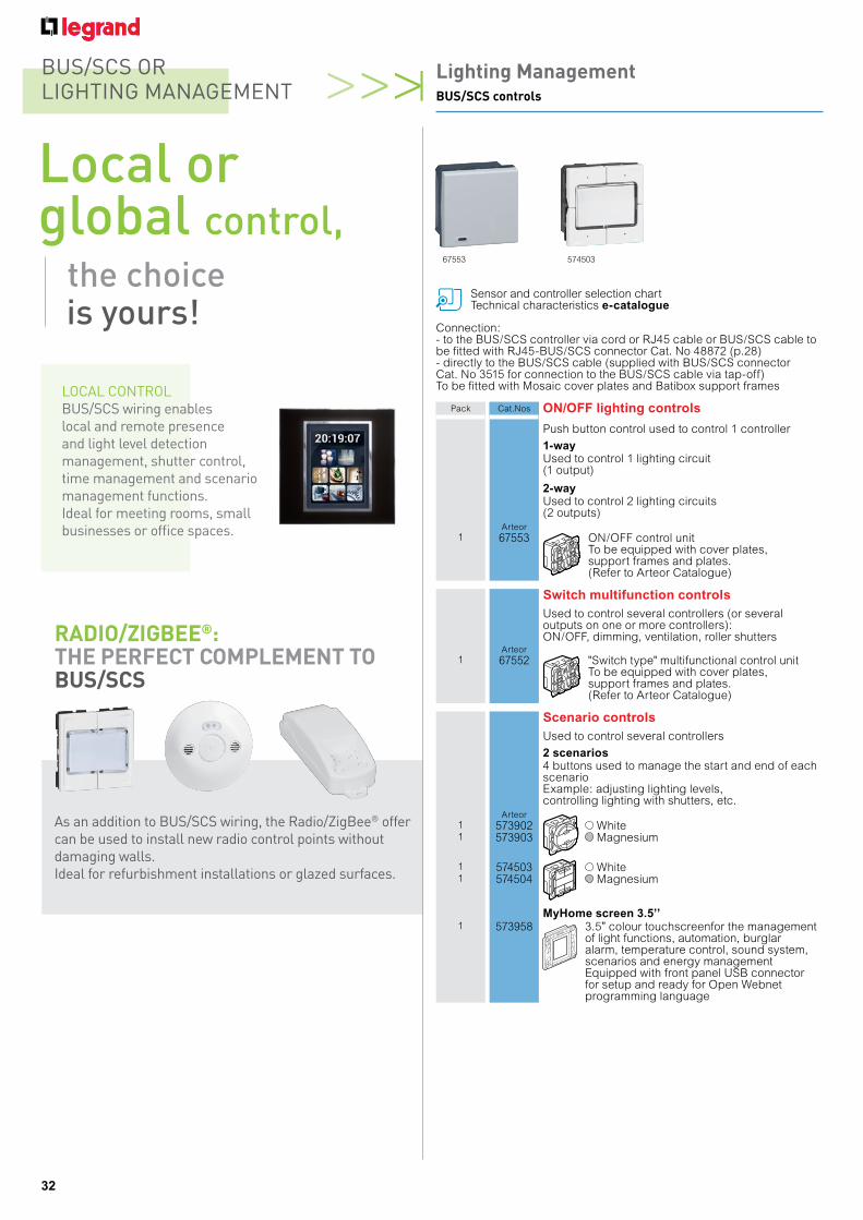
67553 574503
Connection:- to the BUS/SCS controller via cord or RJ45 cable or BUS/SCS cable to be fitted with RJ45-BUS/SCS connector Cat. No 48872 (p.28)- directly to the BUS/SCS cable (supplied with BUS/SCS connector Cat. No 3515 for connection to the BUS/SCS cable via tap-off)To be fitted with Mosaic cover plates and Batibox support frames
Pack Cat.Nos ON/OFF lighting controls
Push button control used to control 1 controller
1-wayUsed to control 1 lighting circuit (1 output)
2-wayUsed to control 2 lighting circuits (2 outputs)
Arteor1 67553 ON/OFF control unit
To be equipped with cover plates, support frames and plates. (Refer to Arteor Catalogue)
Switch multifunction controlsUsed to control several controllers (or several outputs on one or more controllers): ON/OFF, dimming, ventilation, roller shutters
Arteor1 67552 "Switch type" multifunctional control unit
To be equipped with cover plates, support frames and plates. (Refer to Arteor Catalogue)
Scenario controlsUsed to control several controllers
2 scenarios4 buttons used to manage the start and end of each scenarioExample: adjusting lighting levels, controlling lighting with shutters, etc.
Arteor1 573902 White1 573903 Magnesium
1 574503 White1 574504 Magnesium
MyHome screen 3.5’’1 573958 3.5” colour touchscreenfor the management
of light functions, automation, burglar alarm, temperature control, sound system, scenarios and energy management Equipped with front panel USB connector for setup and ready for Open Webnet programming language
32
Lighting ManagementBUS/SCS controls
BUS/SCS OR LIGHTING MANAGEMENT
As an addition to BUS/SCS wiring, the Radio/ZigBee® offer can be used to install new radio control points without damaging walls. Ideal for refurbishment installations or glazed surfaces.
RADIO/ZIGBEE®: THE PERFECT COMPLEMENT TO BUS/SCS
LOCAL CONTROLBUS/SCS wiring enables local and remote presence and light level detection management, shutter control, time management and scenario management functions. Ideal for meeting rooms, small businesses or office spaces.
Local or global control, the choice is yours!

33
Notes

EXB
1301
6 - D
ecem
ber 2
015
HPM
L052
3
HPM Legrand - AUS1300 369 777www.legrand.com.au
HPM Legrand - NZ0800 476 009www.legrand.co.nz