Pushing and Entering - UCSB Nanofabrication Facility …€¦ · · 2012-06-28with a Si. Ca....
56
Pushing and Entering
Transcript of Pushing and Entering - UCSB Nanofabrication Facility …€¦ · · 2012-06-28with a Si. Ca....

Pushing and Entering

Dressed Blades versus Non Dressed Blades
Low diamondexposure
Low machinability
High diamondexposure
High machinability
High loads

Blade Edge Grinding
Silicon Carbide wheel
Blade
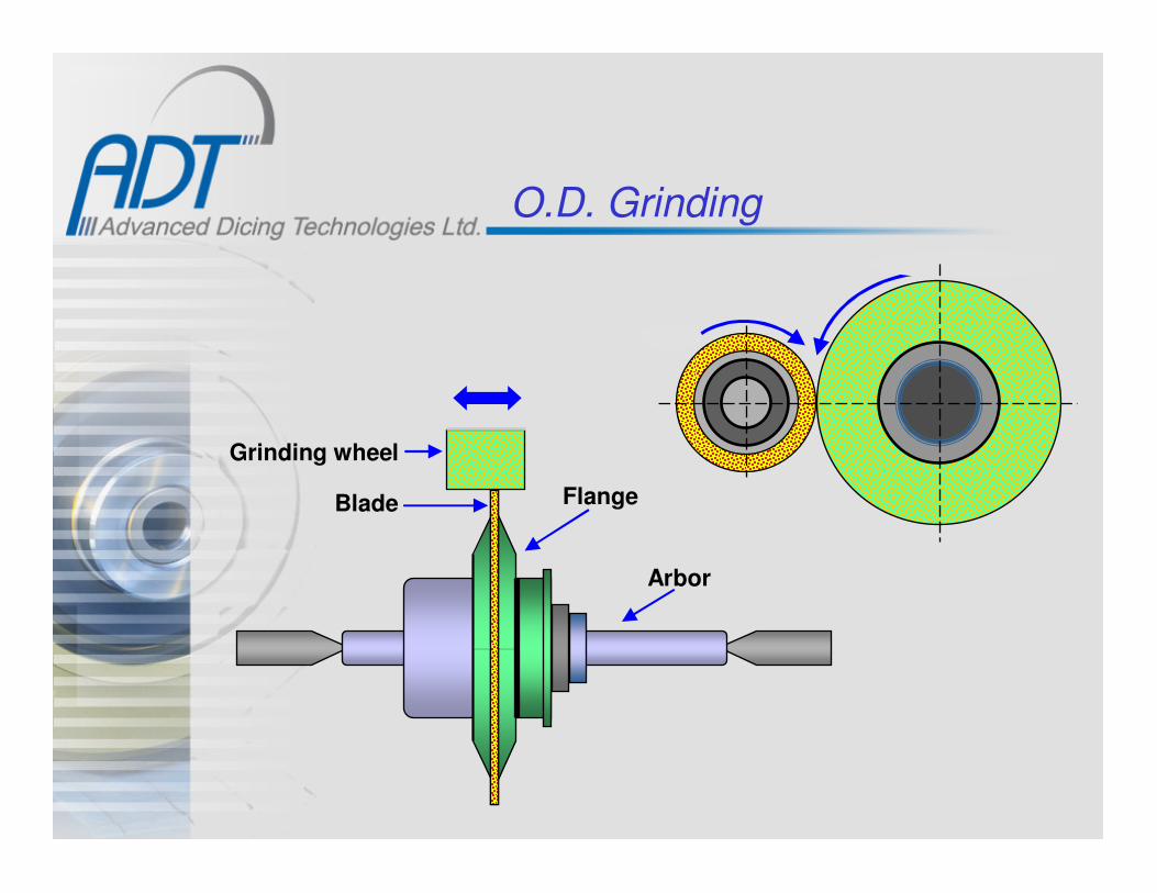
O.D. Grinding
Blade
Grinding wheel
Flange
Arbor
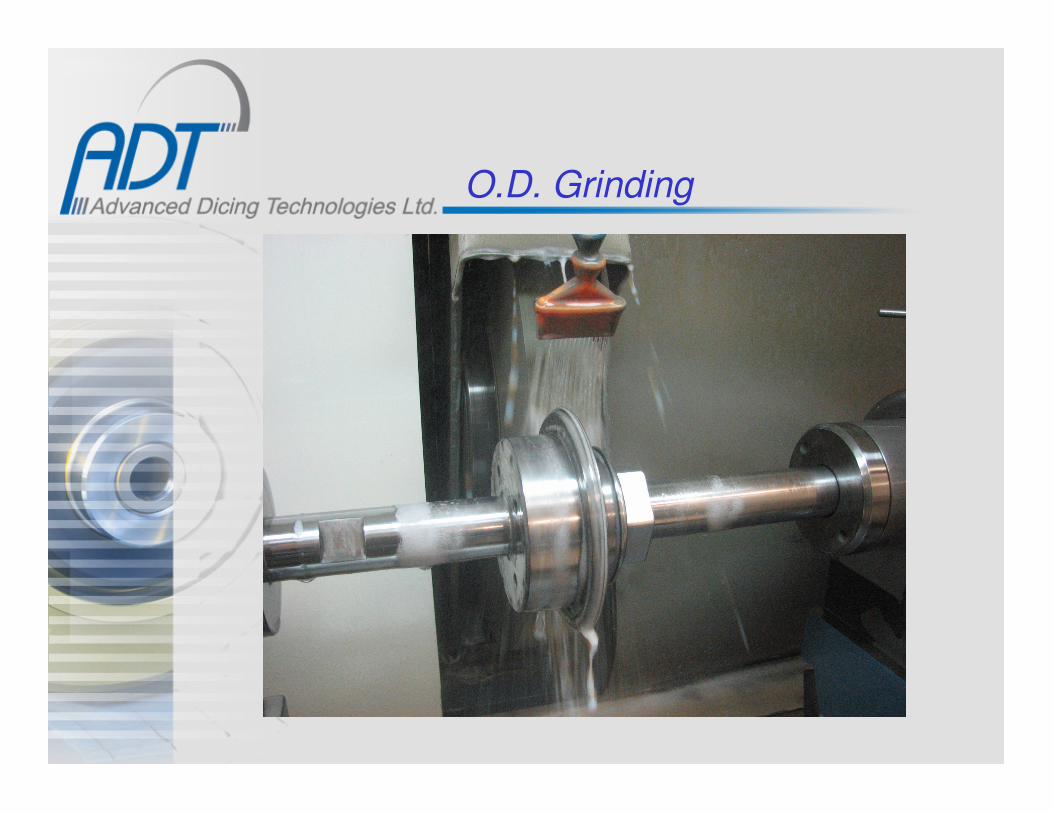
O.D. Grinding

Profile Grinding
Blade
Sil. Car. Grinding wheel
Angled cutAngled cut

Dressing Machine

Dressing Machine

Dressing
Nickel blade17mic. Grit - 330x / 1000x
after Electropolishing
Nickel blade
17mic. Grit - 100xafter Electropolishing
Nickel blade
17mic. Grit - 100x
After fine grindingwith a Si. Ca. wheel

On Line Dressing
Sil. Carbide or Al. Oxide Dressing Stick.
Substrate
After each cut the blades is passing a dressing media.
Feed
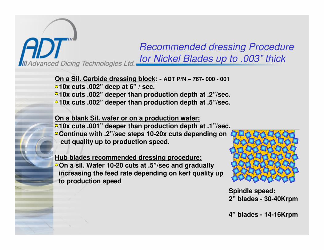
Recommended dressing Procedure
for Nickel Blades up to .003” thick
Spindle speed:
2” blades - 30-40Krpm
4” blades - 14-16Krpm
On a Sil. Carbide dressing block: - ADT P/N – 767- 000 - 001
• 10x cuts .002” deep at 6” / sec.• 10x cuts .002” deeper than production depth at .2”/sec.• 10x cuts .002” deeper than production depth at .5”/sec.
On a blank Sil. wafer or on a production wafer:• 10x cuts .001” deeper than production depth at .1”/sec.• Continue with .2”/sec steps 10-20x cuts depending on
cut quality up to production speed.
Hub blades recommended dressing procedure:• On a sil. Wafer 10-20 cuts at .5”/sec and gradually
increasing the feed rate depending on kerf quality upto production speed

Recommended dressing Procedure
for Nickel Blades Over .003” thick
On a Sil. Carbide dressing block:• 20x cuts .002” deep at 6”/sec.• 10x cuts .020” deep at .5”/sec• Make a height calibration on the saw• 10-20x cuts .001” - .002” deep at 1”/sec
On a production substrate:• Depending on the material being diced, start at
min. feed rate and at production depth.Increase the feed rate every 10-20x cuts dependingon kerf quality up to production speed
Spindle speeds:2” blade - 25-35Krpm3” blade - 15-25Krpm
4” blades - 10-15Krpm
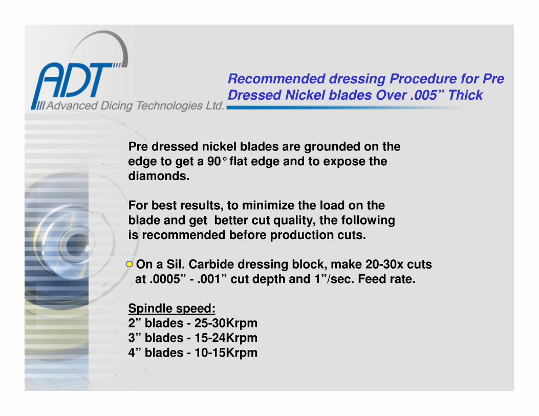
Recommended dressing Procedure for Pre
Dressed Nickel blades Over .005” Thick
Pre dressed nickel blades are grounded on theedge to get a 90°flat edge and to expose thediamonds.
For best results, to minimize the load on the
blade and get better cut quality, the followingis recommended before production cuts.
• On a Sil. Carbide dressing block, make 20-30x cutsat .0005” - .001” cut depth and 1”/sec. Feed rate.
Spindle speed:2” blades - 25-30Krpm3” blades - 15-24Krpm
4” blades - 10-15Krpm
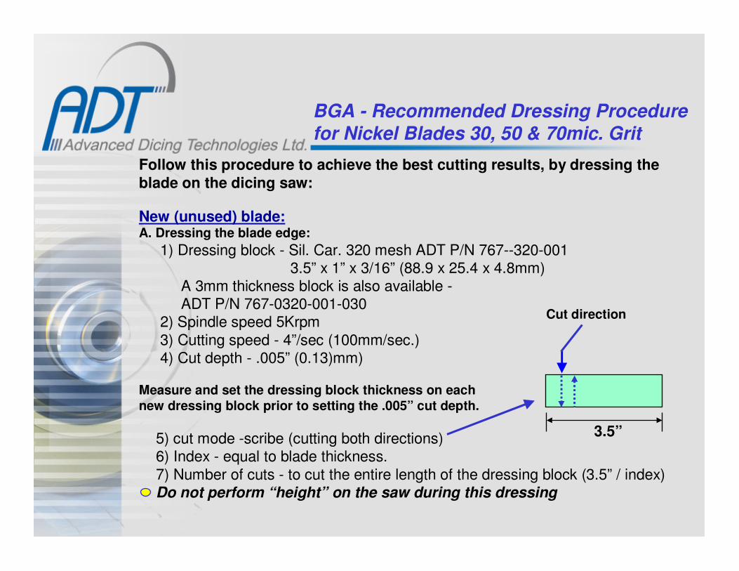
BGA - Recommended Dressing Procedure
for Nickel Blades 30, 50 & 70mic. Grit
Follow this procedure to achieve the best cutting results, by dressing the
blade on the dicing saw:
New (unused) blade:A. Dressing the blade edge:
1) Dressing block - Sil. Car. 320 mesh ADT P/N 767--320-0013.5” x 1” x 3/16” (88.9 x 25.4 x 4.8mm)
A 3mm thickness block is also available -ADT P/N 767-0320-001-030
2) Spindle speed 5Krpm
3) Cutting speed - 4”/sec (100mm/sec.)4) Cut depth - .005” (0.13)mm)
Measure and set the dressing block thickness on each
new dressing block prior to setting the .005” cut depth.
5) cut mode -scribe (cutting both directions)6) Index - equal to blade thickness.
7) Number of cuts - to cut the entire length of the dressing block (3.5” / index)Do not perform “height” on the saw during this dressing
Cut direction
3.5”

BGA - Recommended Dressing Procedure
for Nickel Blades 30, 50 & 70mic. Grit
Cont.
B. Dressing the blade edge & side surface:
1) Dressing block - Same as above.2) Spindle speed - 2” blades - 20Krpm. 3” blades 15Krpm3) Cutting speed - 1”/sec (25mm/sec)4) Cut depth - .004” - (0.1mm) deeper than production depth5) Cut mode - Dice
6) Index - .040” (1mm)7) Number of cuts - 4x
C. In process dressing (After production overloading):1) Dressing block - same.2) Spindle speed - 5K3) Cutting speed - 1”/sec (25mm/sec)
4) Cut depth - .004” (0.1mm) deeper than production depth5) Cut mode - Dice6) Index - .040” (1mm)7) Number of cuts - 6-8x
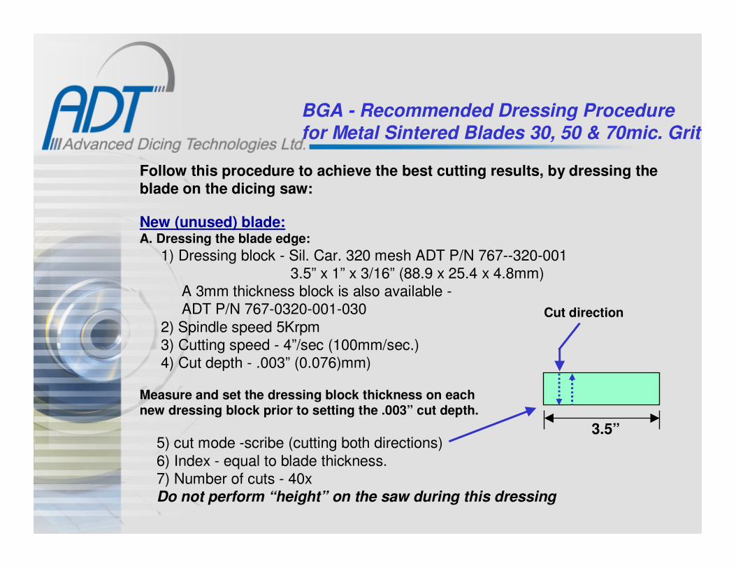
BGA - Recommended Dressing Procedure
for Metal Sintered Blades 30, 50 & 70mic. Grit
Follow this procedure to achieve the best cutting results, by dressing theblade on the dicing saw:
New (unused) blade:A. Dressing the blade edge:
1) Dressing block - Sil. Car. 320 mesh ADT P/N 767--320-0013.5” x 1” x 3/16” (88.9 x 25.4 x 4.8mm)
A 3mm thickness block is also available -ADT P/N 767-0320-001-030
2) Spindle speed 5Krpm3) Cutting speed - 4”/sec (100mm/sec.)4) Cut depth - .003” (0.076)mm)
Measure and set the dressing block thickness on eachnew dressing block prior to setting the .003” cut depth.
5) cut mode -scribe (cutting both directions)
6) Index - equal to blade thickness.7) Number of cuts - 40xDo not perform “height” on the saw during this dressing
Cut direction
3.5”
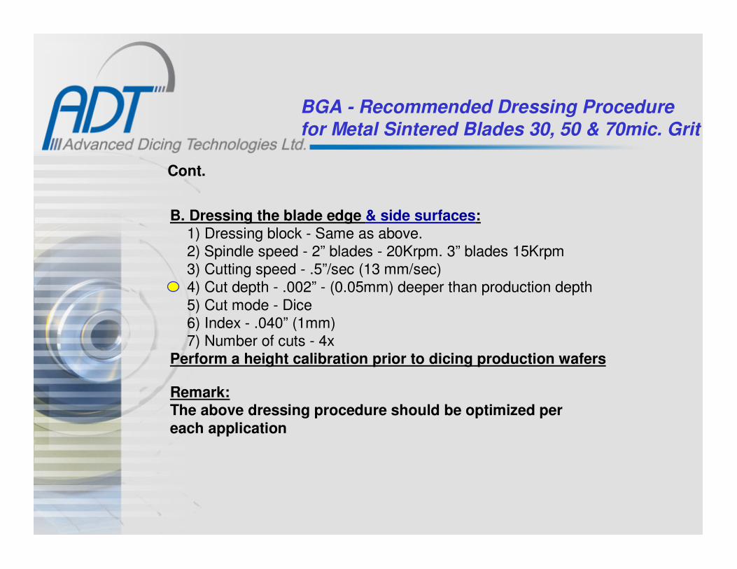
BGA - Recommended Dressing Procedure
for Metal Sintered Blades 30, 50 & 70mic. Grit
Cont.
B. Dressing the blade edge & side surfaces:1) Dressing block - Same as above.2) Spindle speed - 2” blades - 20Krpm. 3” blades 15Krpm3) Cutting speed - .5”/sec (13 mm/sec)4) Cut depth - .002” - (0.05mm) deeper than production depth
5) Cut mode - Dice6) Index - .040” (1mm)7) Number of cuts - 4x
Perform a height calibration prior to dicing production wafers
Remark:The above dressing procedure should be optimized per
each application
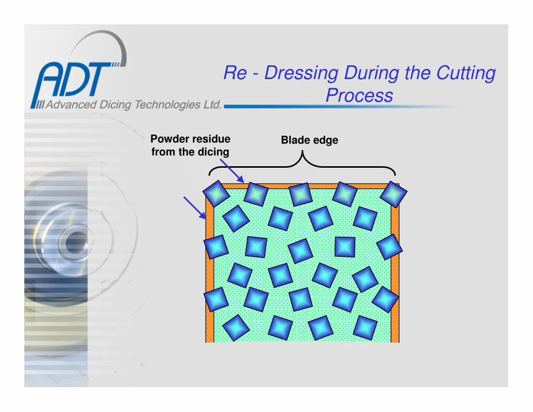
Re - Dressing During the Cutting Process
Powder residuefrom the dicing
Blade edge

Process Techniques & Parameters

Application Characteristics
Blade
Flange
Spindle
Coolant
Substrate
Part
Medium
SpindleDiameterRPM
Torque
Vibrations
BladeDiameter
Thickness
Binder
Grit & %
Edge geom.
Chuck, Fixture Feed rate
Part
Material
Thickness
Straightness
Conductivity
Patterns
Mounting
Holding:
Magnetic
E. Magnetic
VacuumM. Clamping
Substrate:
Glass
AluminaSilicon
Lava
None
Medium:
Tape
NoneCement
Double stick
Wax
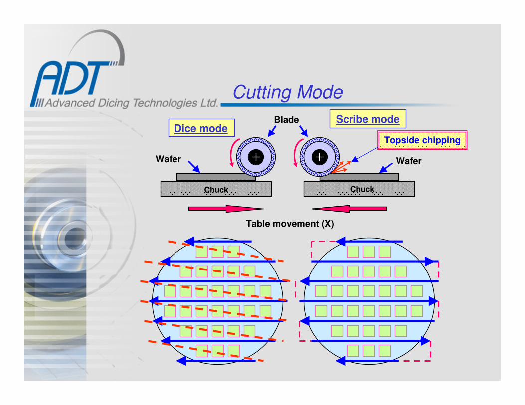
Cutting Mode
Dice modeScribe modeBlade
Wafer Wafer
Chuck Chuck
Table movement (X)
Topside chipping

Application Characteristics

Mounting Methods
Vacuum (Ring chuck)Glue, Wax
Tape on vacuum
Magnetic• Mechanical• Electrical

Special Clamping Methods
Fiber optic
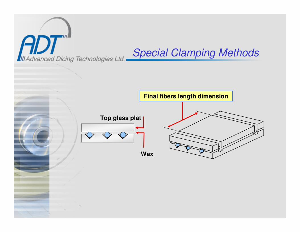
Special Clamping Methods
Wax
Top glass plat
Final fibers length dimension

Special Clamping Methods
Heavy gauge glass plate
Wax Fibers.050”
90°
.010”
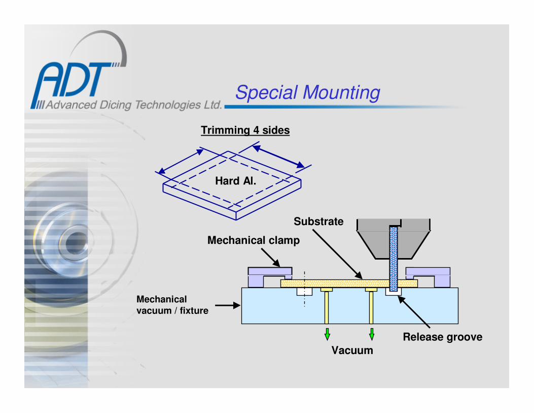
Special Mounting
Mechanical
vacuum / fixture
Hard Al.
Trimming 4 sides
Mechanical clamp
Substrate
Release groove
Vacuum
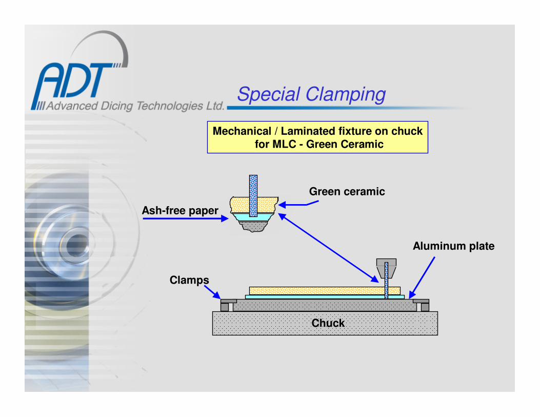
Special Clamping
Mechanical / Laminated fixture on chuckfor MLC - Green Ceramic
Ash-free paper
Green ceramic
Clamps
Aluminum plate
Chuck
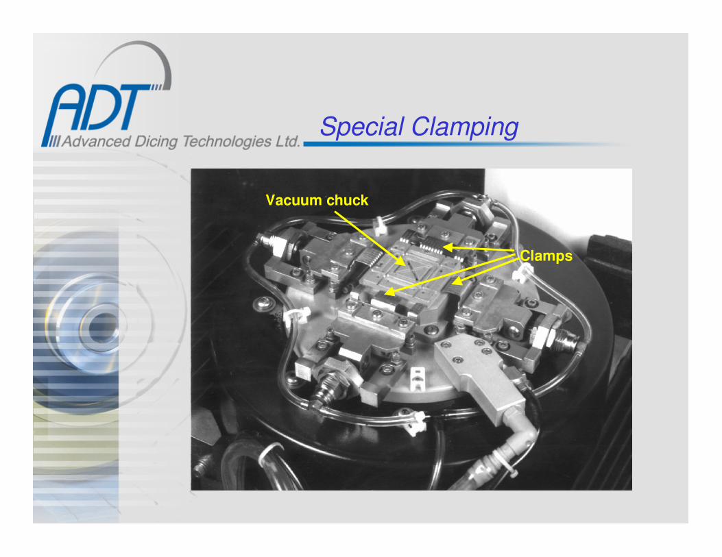
Special Clamping
Vacuum chuck
Clamps

Blade Cooling
Side viewAir knife
Front view

Blade Coolant
• Direction & Flow rate:
Main jet adjustment:
– Too low - does not provide effective cooling
– Too high - may increase blade vibrations, blade straightness
& poor substrate coolant
– Too much pressure can lead to die lift off

Blade Coolant with Additives
Coolant additives results in:
• Lowers the surface tension of the coolant
for better coolant penetration.
• Minimizes the load
• Better washing of dicing dust
With additive Without additive

The Effect of Hub Geometry on the Coolant Flow
Vacuum chuck
Tape
Normal waterflow
Dicing blade
Air knife
Deflected water
flow by the airknife effect
Sil. wafer
Old hub design
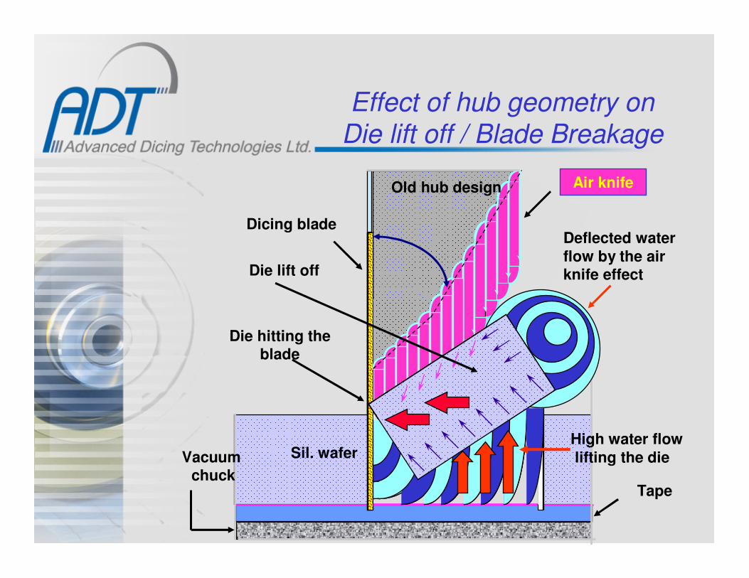
Effect of hub geometry on Die lift off / Blade Breakage
Vacuum chuck
Tape
Dicing blade
Air knife
Deflected water
flow by the airknife effect
Sil. wafer
Old hub design
High water flow
lifting the die
Die lift off
Die hitting theblade
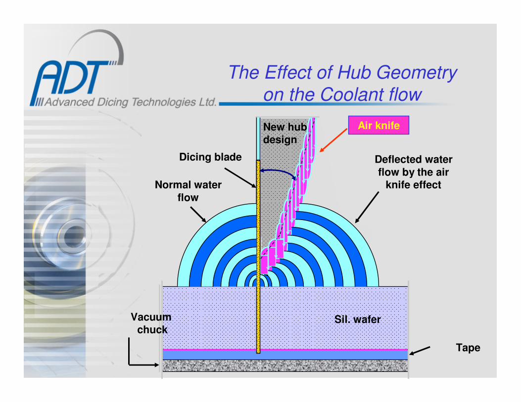
The Effect of Hub Geometry on the Coolant flow
Vacuum chuck
Tape
Dicing blade
Normal water
flow
New hub design
Air knife
Deflected water
flow by the airknife effect
Sil. wafer

Effect of Hub Geometry on Die Lift off / Blade Breakage
Vacuum chuck
Dicing blade
New hub design
Air knife
Deflected water
flow by the airknife effect
Sil. wafer
Die lift off
Die far away from the blade exposure
High water flowlifting the die
Tap
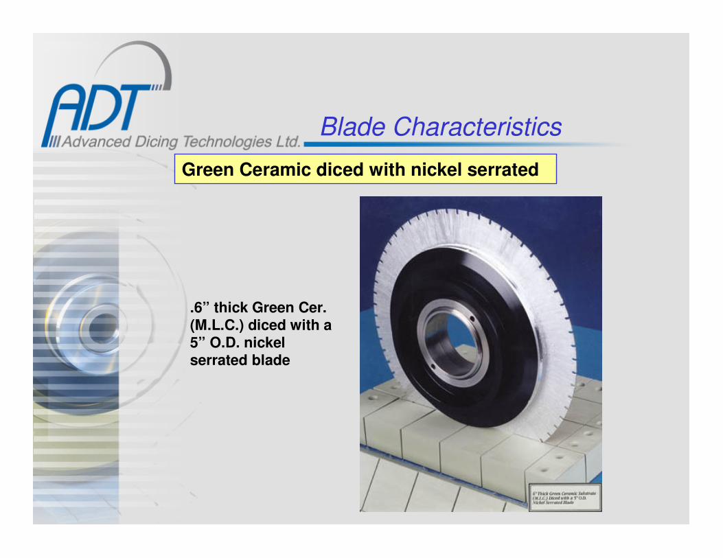
Blade Characteristics
Green Ceramic diced with nickel serrated
.6” thick Green Cer.(M.L.C.) diced with a5” O.D. nickel serrated blade

High Cooling Flange set-up
Cooling nozzle
Coolant
Front guard

High Cooling Flange set-up
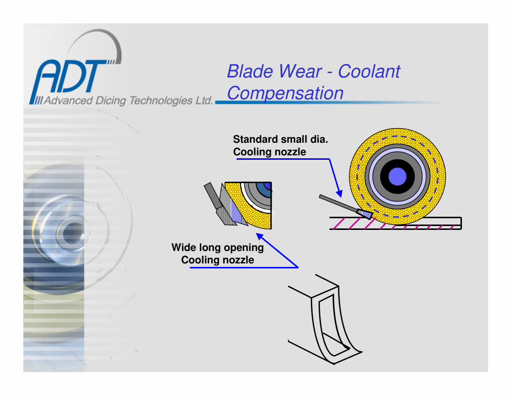
Blade Wear - Coolant Compensation
Standard small dia.
Cooling nozzle
Wide long openingCooling nozzle

Cutting Through into Tape
.001” min.(0.025mm)
Silicon wafer or others
Tape
Adhesive
.0002”(0.005mm)
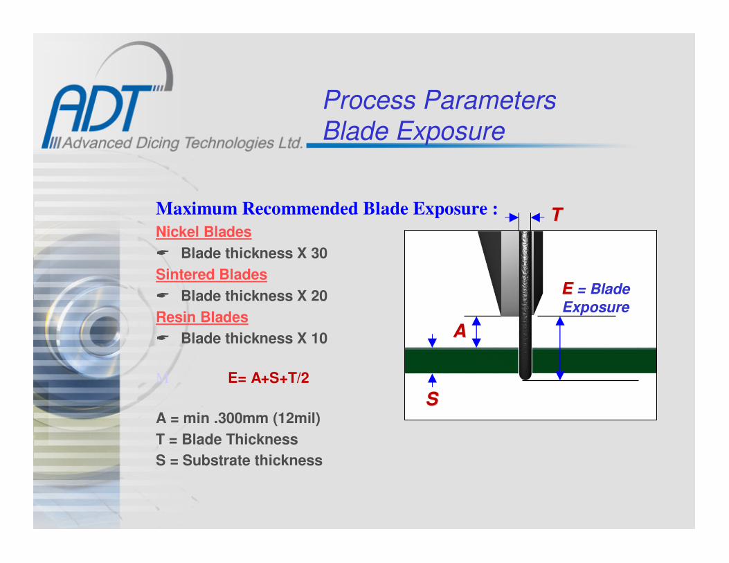
Process ParametersBlade Exposure
Maximum Recommended Blade Exposure :
Nickel Blades
� Blade thickness X 30
Sintered Blades
� Blade thickness X 20
Resin Blades
� Blade thickness X 10
M E= A+S+T/2
A = min .300mm (12mil)
T = Blade Thickness
S = Substrate thickness
EE = Blade
Exposure
AA
TT
SS

Exposure Left
Tape
Recommended exposure left on thin blades for Sil. application
Exposure left
Min. Exp. Left.005” (0.127mm)
Max Exp. Left
.010”(0.254mm)

Cutting Through - Thick Substrate
R=T
2R
The Theoretical max. radius on the blade edge =50% of blade thickness
It is important to dice .005” - .010” (0.13-0.25mm)
A shallower cut will result in a lip effect at the back side= Back side chipping & device size issues
90°.005”- .010”
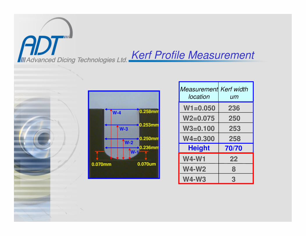
Kerf Profile Measurement
3W4-W3
8W4-W2
22W4-W1
70/70Height
258W4=0.300
253W3=0.100
250W2=0.075
236W1=0.050
Kerf widthum
Measurementlocation
W-1
W-2
W-3
W-4
0.236mm
0.250mm
0.253mm
0.258mm
0.070mm 0.070um

Process ParametersCut Depth into tape
Deeper cut Shallow cut
• Deeper cut reduces blade radius affect.
• Optimum cut depth = 0.5 x blade thickness.

Dicing Green Ceramic
Wet process:Using nickel serrated blades 17, 30, 50 & 70mic. Grit
For better cut quality anon serrated blade can be used
Dry Process:Using nickel blades and Tungsten carbides(Same diamond grit as with the wet process)
Ceramic powder
laminated tothe blade sides
Tungsten carbide blade:Advantages - A cleaner cut in some applicationsDisadvantages - Short life, poor availability, blade breakage
Nickel blade:
Advantages - Minimum blade wearEasy handlingAvailability
Disadvantages - Powder build-upExtra blade cleaning is needed
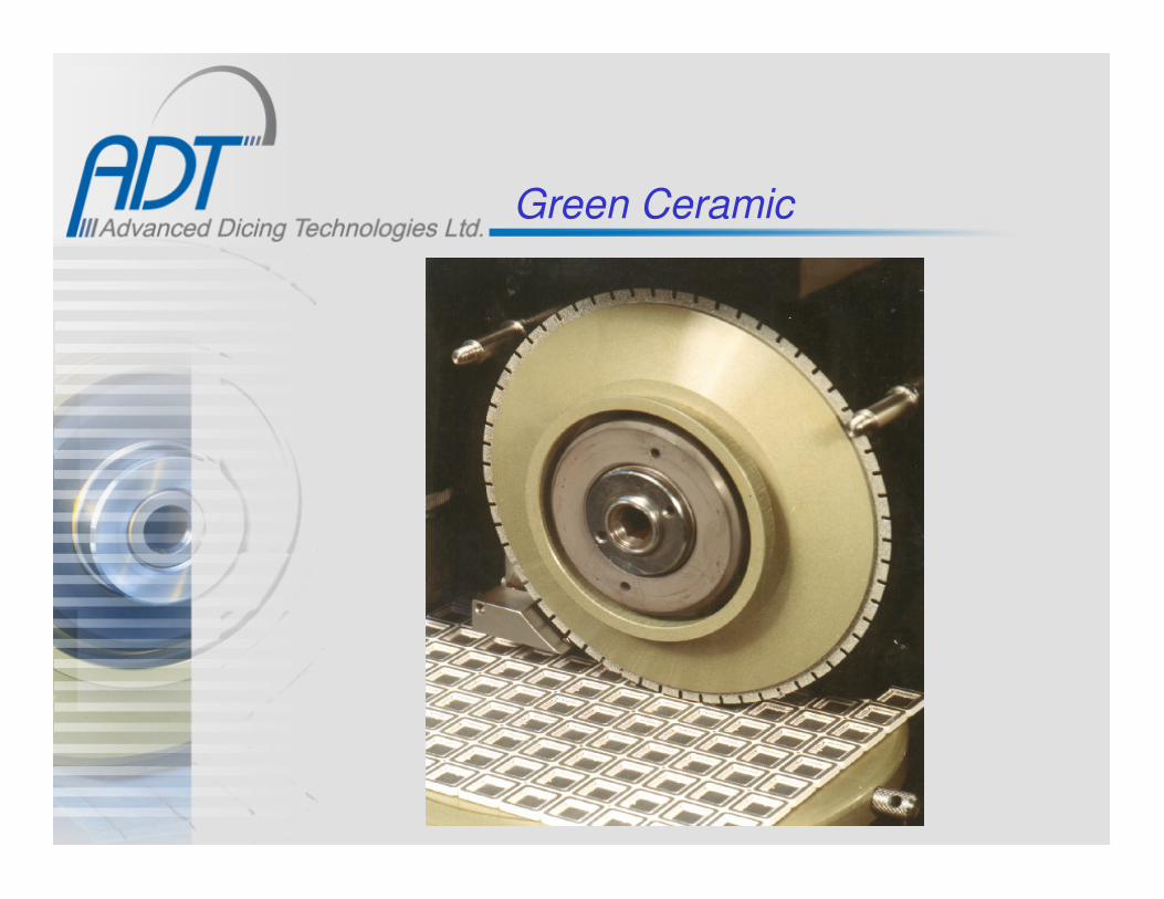
Green Ceramic

Dicing Seminar

Material Dicing Guide -Blade related
Material RemarksHardn. Brittleness
Hard Resin
Soft
Ruby GWK 53,63 No No
Alumi. Nitride KUP, RUP 63-105 No No
Alumina KUP, RUP 45-63 No NoAlso with
standard matrix
Titanium Car. KUP, QKP 30-53 Yes 10-30 Yes 10-25
Kovar AUP 53,63 No No
Quartz QIP, KUP 30 No No
Glass / Pyrex KUP, QIP 30,45 No No
PZT AUP 9-45 Yes 3-6,10 No
Barium Titan. QUP, QKP 20-45 No No + QIP Softer
Led Telluride
Lithium Niob. KUP,QUP 15-30 Yes 3-6 No
Bismuth Telur. RUP, KUP 45,53 Yes 17,30 No
Silicon QUP 9 Yes 4-6 No
GaAs Yes 2-4 No
Ferrite AUP, QIP 4-30 Yes 3-6,10 Yes 2-30
Soft
Blade Matrix & Diamond Grit Blade Matrix & Diamond Grit [mic.]
Resin , Grit Nick., Grit Sint. , Grit
53,63 No No
Yes 3-6 No
Sapphire
QFN E06,T04&6 53-70 No Yes 53
QKP

Popular Resin Matrices
For very brittle & Very soft and loading materials wearing matrix.
Matrix CodeMatrix Code Hardn.Hardn. Subst. MaterialSubst. Material RemarksRemarks
Hard Alumina Graphite Fib.Min. Wear.
RUP, RFP
KUP & KKP
and others.
Hard Al., some Glass, Best wear onBismuth Tel. Others new matrix.
-------”------- , Al. Nitr. Direct [First]T.Carbide, Lithium - replacement to-Niobate, others. our Standard m.Same as above but Softer thanthicker subst., more KUPLoading.
IUP
QUPSame subst.materials Will Minimizeas KUP but more chipping.Brittle.Same subst. materials Will minimize as KUP but more Chipping & brittle & thicker. loading.
Sapphire & Ruby 53 & 63mic grit
QKP
QIPQuartz, Glass, Soft wearing mat.Barium Titanate resulting in good& other brittle mat. edge quality.
AUPPZT, some thicker Al. Soft resin but Kovar, some ferrites. high dia. %
For small grits.
AIP
Standard
E- Series: E01, E03, E06To minimize wear and improve cut quality on QFN
T- Series: T04 & T06New developments for QFN
Hard materials Requiring high blade wear
V. Soft bond withLow diamond %
C- Matrices: C02 & C03Improved wear and qualityfor hard Alumina
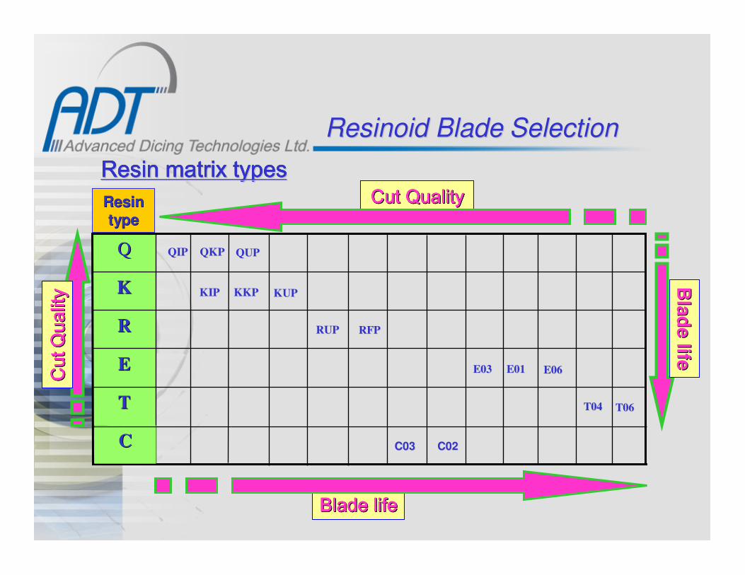
ResinoidResinoid BladeBlade SelectionSelection
T06T06T04T04TT
E06E06E01E01E03E03EE
RFPRFPRUPRUPRR
KUPKUPKKPKKPKIP KIP KK
QUPQUPQKPQKPQIPQIPQQ
ResinResin
typetype
Cut QualityCut QualityCut QualityCut QualityCut QualityCut QualityCut QualityCut Quality
Blade lifeBlade lifeBlade lifeBlade lifeBlade lifeBlade lifeBlade lifeBlade life
Cut
Cut
Cut
CutCut
Cut
Cut
Cut
Qua
lity
Qua
lity
Qua
lity
Qua
lity
Qua
lity
Qua
lity
Qua
lity
Qua
lity
Resin matrix typesResin matrix typesResin matrix typesResin matrix typesResin matrix typesResin matrix typesResin matrix typesResin matrix types
Bla
de life
Bla
de life
CC C03 C02C03 C02

Material Dicing Guide -Blade related
Material
FR4, Plastic & BT Resin
FR4 & Copper
TiC & Ferrite
PZT
GaAs
LiNbO3, LiTaO3
Silicon
Green Ceramic
FR4, Plastic & BT Resin
Alumina
Alumina
Copper + Resin
Quartz, LiNbO3, LiTaO3
Ferrite
Glass, Quartz
TiC
FR4, Plastic & BT Resin
Glass, Quartz
Copper + Resin
Alumina
Blade Type Diamond size Product
Micron
Nickel Blade 30,50,70 PBGA
6-8,10,17 PCB
3-6,10,17 Magnetic & Tape Heads
2-4,4-8,10 Ultrasound Sensors
2-4,3-6 Active Devices ( Discrete )
4-8 SAW Devices
2-4,3-6 IC's
Steel Core Ni Blades 30,50,70 MLC ( Multi Layer Capacitors )
30,50 PBGA
Resinoid Blades 53,88,105 CBGA
53,63,88 Ceramic Packages
75,88,105 QFN/MLP ( F/C & H/E )
15,20,30 SAW Devices
6,9 Tape for VTR
30,45 Ink Jet Print Heads, Fiber Optics
Sintered Blades 9,15,25 Magnetic Heads
30,50 PBGA (Tape & Tapless application)
9,10,15 Fiber Optics
30,40,50 QFN/MLP ( H/E )
20,30,40 Ceramic Packages

Recommended ValuesRecommended Values
Blade Blade Matrix Diamond size Spindle Speed
Type O.D mic KRPM mm/s Inch/s
2" 2": 30-45
3" 3": 20-30
2" 2": 25-30
3" 3": 15-28
2" 2": 25-30
4" 4": 15-28
2" 18-28
4" 10-18
Multi Layer Capacitor Green CeramicNickel
Steel Core4" 30, 50, 70 12-18 100-250 4-10
Ultrasound Sensors PZT Nickel 2" 2-4, 4-8, 10 25-35 0.5-10 0.02-0.4
IC Silicon Nickel 2" 2-4, 3-6 30-50 25-75 1-3
Resin 45,53, 63* KUP , RUP 4-20 0.15-0.8
Product Material
FR4 / Epoxy &
Cooper
Epoxy & Molding
NickelPCB
Ceramic Packages Alumina
50-125 2-5
30, 40, 50PBGA
QFN
Sintered /
Nickel
Cooper & Molding Resin
Feed Rate
"T" , "V" ,
"Z"10 , 13 , 17 100-150 4-6
100-200 4-8
Resin: E
type 88, 105, 125
Blade SelectionBlade Selection

Recommended Values (cont.)Recommended Values (cont.)Blade Blade Matrix Diamond size Spindle Speed
Type O.D mic KRPM mm/s Inch/s
2" 16-20
4" 8-10
2" 18-30
4" 8-18
2" 16-30
4" 8-18
2" 20-30
4" 10-15
2" 18-30
4" 8-18
Nickel: 4-8
Resin: 15, 20,
30
Nickel: 3-6, 4-8,
10
Resin: 15, 20, 30
Sintered: 10, 17 Slicing: 8-12 1-5 0.04-0.2
Nickel: 3-6, 10,
15Parting: 8-12 1-10 0.04-0.4
Resin
* QIP , QKP ,
QUP
0.5-2.59, 15, 25* QIP , QKP ,
QUP
0.1-0.4
0.04-0.4
0.02-0.1
0.1-0.4
Resin 2-10
1-1030, 45 ,53
30, 45, 53
* QIP , QKP ,
QUP
* QIP , QKP ,
QUP 30, 45, 53 2-10
Nickel /
Resin
Fiber Optics
components
Glass / Fused
Silica
Fiber Optics
componentsQuartz Resin
Fiber Optics
components Si On Glass Resin
Resin /
Nickel
AlTiCO3Sintered /
Nickel
Tape Head
Magnetic Heads
SAW Devices
Ferrite
SapphireOptical and Electro-
Optics components
LiNbO3 ; LiTaO3 16-30
0.1-0.4
SAW Devices* QUP , KUP
, RUP30, 45, 53 0.1-0.4 2-10Quartz Resin
* QUP , KUP
, RUP2"
4"
Product MaterialFeed Rate
2-10 0.1-0.4
2"* QUP, KUP
, RUP25-35 2-10
Blade SelectionBlade Selection

Maximum Recommended Spindle RPM -(Safety - only)
Nickel Blades: Resinoid:2” O.D. - 40 - 60Krpm 2” up to .015” thick - 35Krpm3” O.D. - 35Krpm 2” .016”- .025”thick - 25Krpm4” O.D. - 30Krpm 2” .026”- .035” thick- 20Krpm
3” up to .015” thick - 25KrpmM. Sintered: 3” .016”- .025”thick - 22Krpm 2” O.D. - 40 - 60Krpm 3” .026”- .035” thick- 16Krpm3” O.D. - 35Krpm 4” up to .015” thick - 16Krpm4” O.D. - 30Krpm 4” .016”- .025”thick - 14Krpm
4” .026”- .035” thick- 12Krpm