Purlins and Truss
17
120 Chapter 3 DESIGN OFPURLINSAND TRUSSES 3.1. DESIGN OF PURLIN Design ofpurlin sizes are based on an analysis ofbending members as a simple beam. The length of the purlin from truss to truss istaken as the span length needed for the single span, simply supported beam formula. This is a conservative approach as it provides for a larger bending moment than that obtained bytrue engineering analysis. Illustrative Example Let purlinspacing = 4' - 0" C/C Trussspacing = II' - 0" C/C Truss span = 50' - 0" L. L = 16 psf Sheathing = 2 p sf Roofing material = 4.5 psf Use PyinKado. Unit wt . = 60 pcf Assume S'' x2" purlins are used. L .L Roofing Sheathing 704 Lb 198 Lb 88 Lb = 16x4x 11 4.5 x 4 x 11 = 2x4xll = = Own wt . 5 x 2 144 x 60 x 11 45.83 w = 1035.83 Ib 1 8 e = tan- 1 2 5 = 35.754 W N = W Cos e = 1035.83 x os 35.754 = 840.61 Lb W T = W Sin e =1035.83 x Sin 35.754 = 605.24 Lb WNL 840.61x(11x12) Mx = 8 = 8 =13870.07 in-lb L b
-
Upload
umesh-bagli -
Category
Documents
-
view
235 -
download
0
Transcript of Purlins and Truss

8/6/2019 Purlins and Truss
http://slidepdf.com/reader/full/purlins-and-truss 1/16
120
Chapter 3
DESIGN OFPURLINSAND TRUSSES
3.1. DESIGN OF PURLIN
Desig n o f p urlin siz es are b ase d o n an a naly sis o f b en din g members as a simp le b eam .
T he length of the purlin from truss to truss is taken as the span length needed for the single
sp an , sim ply su pp orted b eam fo rm ula. T his is a co nserv ativ e ap pro ach as it p ro vid es fo r a
l ar ge r bend ing moment than that ob ta ined by tr ue eng inee ring ana ly si s.
Illustrative Example
Let pur lin spacing = 4' - 0" C /C
Truss spacing = II' - 0" C/C
Truss span = 50' - 0"
L.L = 16 p sf
Sheathing = 2 psf
Roof ing materia l = 4.5 p sf
U se PyinKado. Un it wt. = 60 p cf
Assume S '' x 2" p url i ns are u sed .
L .L
Roofing
Sheathing
704 Lb
198 Lb
88 Lb
= 16x4x 11
4.5 x 4 x 11
= 2x4xll
=
=
Own wt.
5x2
144 x 60 x 11 45.83
w = 1035.83 Ib
18
e = tan-1 25 = 35.754
WN= W Cos e = 1035.83 x Cos 35.754 = 840.61 L b
WT
= W Sin e =1035.83 x Sin 35.754 = 605.24 L b
WNL 840.61x(11x12)M x = 8 = 8 =13870 .07 in -lb
Lb

8/6/2019 Purlins and Truss
http://slidepdf.com/reader/full/purlins-and-truss 2/16
121
SO'-O"
Zx = 1.7Sx(4.7S)2 =6.S8 in3
8
\~
13870.076.S8 = 2107.91 psi
Similarly,
MWTL
=y 8
Z4.7Sx(1.7S)2
=y 6
0' =by Zy
If (J'tot = 0' bx + 0' by s allowable Fb ' OK.
Deflection Check
L llx12Allowable max: deflection from AITC = 120 = 120 = 1.10"
WDN =(wt. of roofing + own wt. + sheathing) x Cos e
= (198 + 4S.83 + 88) x Cos 35.754°
= 269.291b
WLN =L.LxCose =704xcos35.754°=571.32Lb
bd3 _ 1.7Sx(4.75)3 _ . 4I = 12 - 12 - 15.63 m
5 (2WDN+WLN)= L3384 EI
8/6/2019 Purlins and Truss
http://slidepdf.com/reader/full/purlins-and-truss 3/16
Similarly,
If actual
122
5 (2WDT+WLT) 3
Ay = 3 8 4 EI L
A = ~(!1x)2 + (! 1y)2 ~ allowable deflection from AITC, OK.
Choose 5" x 2" purlins.

8/6/2019 Purlins and Truss
http://slidepdf.com/reader/full/purlins-and-truss 4/16
123
3.2. DESIGN OF ROOF TRUSSES
3.2.1. Selection of Roof Trusses
Arch ite ctu ra l s ty le , type s o f roofing ma te ria l, me thod s o f suppor t o f column f raming,
and ralative economy are the principal factors influencing a choice am ong the three basic
ty pes o f tru sses: b owstrin g, p itc hed , an d flat. In a dd itio n, sid e- a nd e nd -wall h eig ht an d ty pe,
ro of sh ap e, a nd b racin g re qu iremen ts must b e consid ered .
O ther fa cto rs being equal, e conomy is th e p rime consid er ation. Economy is dependent
upon e ffic ie ncy in u se o f ma te ria l re la tiv e to tru ss type and p ropo rtions and to f ab ric ation labo r.
Theo retic ally , th e th ree b asic ty pe s in o rd er o f re la tiv e efficie ncy are b owstrin g, p itch ed , an d
flat.
T he function o f a tru ss is to transfer load from point of applicatio n to the supp orts as
directly as possible. T hus for a concentrated load at the centerline of a span, a sim ple IIA"
frame is the most e ff ic ient. L ike-wise, ifon ly two equa l and symmetr ical ly p laced concentrated
lo ad s are in vo lv ed , a tru ss sim ilar to th e q uee n-p ost ty pe is th e mo st effcien t. Inboth trusses,
th e lo ad is tran sfe rred to th e su pport d irec tly th ro ugh th e slo pin g to p-c ho rd membe rs w ith ou t
the need for w eb m embers.
3.2.1.1. Bowstring Trusses
F or m ore or less uniform loads, w hich are usually assum ed in roof construction, an
arc h in th e sh ap e o f a p ara bo la is th eo retic ally th e mo st efficie nt b eca use d irect stre ss a lo ne is
developed in the arch and in the tie m em ber. A parabolic arch has no need for a larger arch
section to take care of b end ing moment, moreo ver, and no n eed to introd uce w eb members to
lessen the amoun t of bending. B ecause most structures must sustain some un balanced lo ad,
h owev er, web members are d esirab le, an d a circu lar arc is simpler to fab ricate th an a p arab olic
o ne. T hus th e w idely used b ow string truss has a top ch ord in a circular arc and su fficien t w eb
members to k eep to p-ch ord size s reaso nab le .
Bowstrin g tru sses a re u su ally an aly zed fo r d irec t stress a s th ough th e to p c ho rd were
in a straight line betw een p anel points. T op chords may be glu ed-lam inated (F ig. 3.1) to the
curv ature or may b e so lid timbers laid to the curv ed pattern w ith or w ith out their top surfaces
saw ed to the curvature (F ig. 3.2). T he bending moment due to eccentricity betw een panel
points m ust be considered both for curved-lam inated m embers and for m embers saw ed to
curvature ifth e cen te rlin e o f th e member d oes n ot c oin cid e w ith th e assumed d irectio n o f ax ial
8/6/2019 Purlins and Truss
http://slidepdf.com/reader/full/purlins-and-truss 5/16
124
stress. If j oists are sp aced alo ng th e to p ch ord , th is seco nd ary b end ing m om en t m ay p erm it
the use of sm aller m em ber sizes than w ould a truly segm ental, saw ed tim ber top chord. In
addi ti on , because o f the ir h igher a ll owable un it s tre ss es , g lued -l am ina ted top cho rds and o ther
g lu ed -lam in ated m embers n orm ally p erm it th e u se o f sm aller sizes. T hey also elim in ate o r
lesse n th e n eed fo r th e sea so nin g main te na nc e re qu ire d b y some sawed members. B ec au se o f
the extra labor involved in lam inating, how ever, they m ay be m ore expensive than saw ed
members .
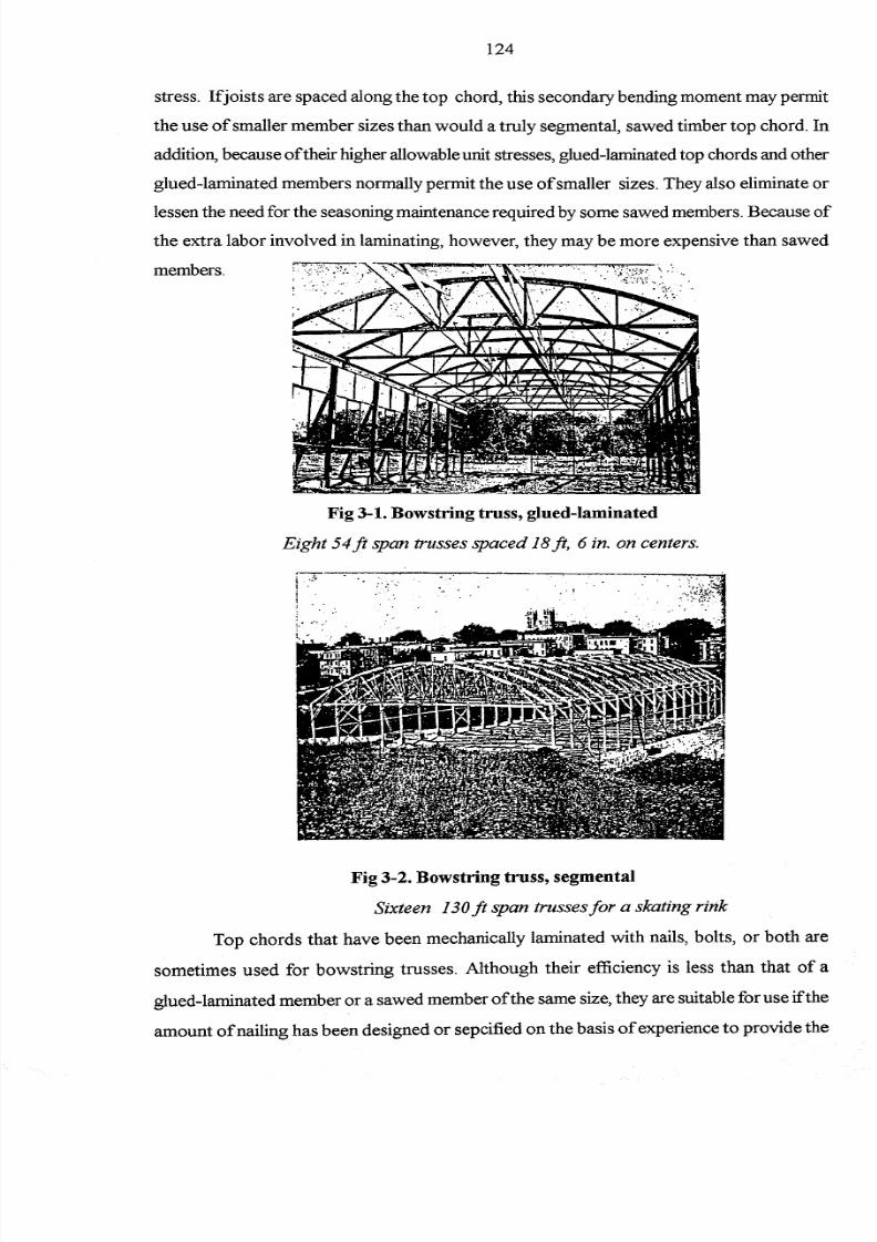
Fig 3-1. Bowstring truss, glued-laminated
Eight 54ft span trusses spaced 18ft, 6 in. on centers.
Fig 3-2. Bowstring truss, segmental
Sixteen 130ft span trusses for a skating rink
Top chords that have been m echanically lam inated w ith nails, bolts, or both are
som etim es used for bowstring trusses. A lthough their efficiency is less than that of a
g lu ed -lam in ated m ember o r a saw ed m ember o f th e sam e size, they are su itab le fo r use ifth e
am ount of nailing has been designed or sepcified on the basis of experience to provide the

8/6/2019 Purlins and Truss
http://slidepdf.com/reader/full/purlins-and-truss 6/16
125
r equir ed str ength o f th e built-up se ction. The se ction w ill u sually be la rger th an that n eeded for
a g lued -laminated membe r, but it w ill a ls o be more suita ble for f ie ld lamination.
A bowstring truss m ay be built up to provide the appearance of either a flat or a
p itc he d tru ss a nd th us is p ro bab ly th e mo st fle xib le o f a ll tru ss ty pe s. F or su ch c on stru ctio ns,
p ro pe r la tera l b ra cin g sh ou ld b e p ro vid ed fo r th at p ortio n o f t he c urv ed to p c ho rd whic h la ck s
d ire ct la tera l su pport from th e ro of framin g. (se e F ig 3 .3 )
Fig. 3-3. Bowstring truss, built-ups
Eighteen 76it span trusses, one 72ft truss, one 68-ft truss.
3.2.1.2. Pitched Trusses
P itched trus se s ( fig . 3 .4 ) have some o f t h e th eo re tic al advan tage s o fbowstr ings in th at
a portion of the load is transferred to the supports directly through the top- chord m embers
and need not be carried through the web m em bers. For average spans, the top chords of
p itched tru sses h av e th e eco nomic ad van tag e of p erm ittin g the u se of saw ed timber w itho ut
special saw ing or fitting to curvature, and of being sim ple to layout and fabricate. W eb-
member an d o th er co nn ection s are also simple, as a rule. L ike tho se ina bowstr ing truss , th ey
a re much le ss comp lic ated th an fla t- tr us s connections.

8/6/2019 Purlins and Truss
http://slidepdf.com/reader/full/purlins-and-truss 7/16
126
Fig. 3-4. Pitched Truss
Eighteen 64it span Belgian trusses.
3.2.1.3. Flat Trusses
F lat tru sse s (F ig . 3 .5 ) are le ss efficien t th an eith er th e p itc hed o r b owstrin g ty pe. The y
a re pre fe rable only ifa relat ively f la t roof sur face , par ticular ly on wi th mult ip le spans , is des ired .
F or lateral-bracing and column conn ectio ns, they have th e adv antage of pro vidin g a b racin g
effect, because both the top and bottom chords m ay be attached to the colum ns. For usual
t russ p ropor tions, the ir web-member s tres ses will be consid er ab ly g re ate r th an those fo r p itc hed
o r b owstrin g tru sses an d th eir web c onne ctio ns more c omplic ate d a nd expen siv e.
Fig 3-5. Flat Pratt truss

8/6/2019 Purlins and Truss
http://slidepdf.com/reader/full/purlins-and-truss 8/16
127
3.2.1.4. Raised-chord Trusses
Raised -c ho rd tru sses(F ig .3 . 6 ) are tru sses w ith th e ce nter p ortio n o f th e b ottom cho rd s
rai sed subs ta in tial ly above the levelof support s. They are f requently used for reasons of appearance
or added clearance. T yp ical examples are crescen t trusses of a bow string type, th e so-called
c ambered o r ra is ed -bottom-cho rd p itc hed tru ss es emp loying Howe, P ra tt, o r F ink web systems,
and scissors trusses. U nless these trusses are analyzed as arches and fixity or resistance to
ho rizontal thrust provided accord ingly at the suppo rt, the effective depth -to -span ratios of
s imp le tru sse s shou ld be ma in ta in ed .
A ra is ed -cho rd tru ss , p artic ula rly one w ith spans , longer th an 50ft, s hould be ana lyzed
fo r th e th ru st on th e walls induced by defle ction, and th e walls o r columns designed accord ingly .
O t herw ise sp ecia l b earin g d etails o r w all fram in g sh ou ld b e p ro vid ed to relie ve th e th ru st.
Ifa tru ss is su pporte d b y masonry , th ru st d ue to d eflec tio n may b e m in im ize d by mean s
of slotted anchorage connections. Roller supports at one bearing are not common except in
la rge spans where more pos itive f ree movemen t is consider ed neces sa ry . Provis ion for def lection
th rust r elie fis most important a t the time of e rection ; la te r the trus s wil have stabilized substaintially.
Ifmaximum vertical liv e load and w ind are assum ed no t to occur at th e sam e tim e, m oreov er,
th e normal p rovis ion fo r w ind lo ad s on th e suppo rts is o fte n con sid ered adequate fo r v ertic al lo ad
deformation thrust.
Fig 3-6. Scissors Truss
Span of 33ft, 616in., 12ft spacing; 45-deg roof slope; 30-deg bottom-chord slope.
F or trusses supported on free-standing colum ns w ith m asonry side w alls, it is w ell to allow
c learan ce fo r la teral d eflectio n b etw een c olumn and wall at th e tim e o f erec tio n. A fte r o rig in al
la te ra l movement, the connections between column and wall may be tightened. Requ ired c lear ance
8/6/2019 Purlins and Truss
http://slidepdf.com/reader/full/purlins-and-truss 9/16
128
may b e d eterm in ed by d efle ctio n ca lcu la tio ns, b ut it is fre qu en tly ra th er a rb itra rily c ho sen on
the bas is o f exper ie nc e.
3.2.1.5. Special Trusses
There are m any other types of trusses as w ell as combinations of the standard types
th at o ffe r s pe cia l a dvan tage s for s pe cia l c onditions . I n gener al, th e s ame recommendations for
p ro po rtio ns, sp acin g, and oth er d esig n details co ntin ue to ap ply . T yp ical combin atio ns are
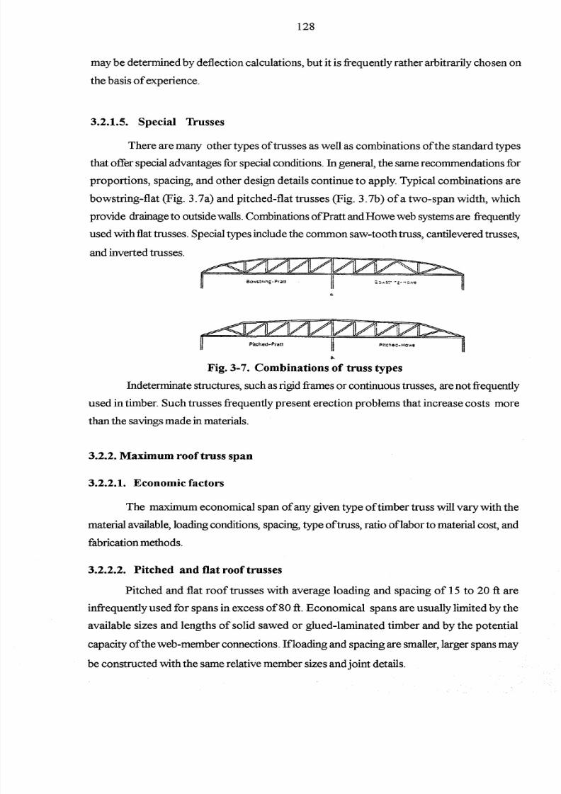
bow string-flat (F ig. 3.7a) and pitched-flat trusses (F ig. 3.7b) ofa tw o-span w idth, w hich
p rovide d ra in age to outsid e wa lls .Comb inations o f P ra tt a nd Howe web systems a re f re quen tly
u sed w ith f la t tr us se s. Specia l type s in clude th e common saw- tooth tr us s, c an tile ve red truss es ,
and inver ted t russes .
b.
Fig. 3-7. Combinations of truss types
I ndete rminate s tr uc tu re s, s uch a s rig id f rames o r con tinuous tr us se s, a re not f re quen tly
u sed in timber. S uch tru sses freq uen tly p resen t erectio n p rob lem s th at in crease co sts more
th an th e sa vin gs mad e in mate ria ls.
3.2.2. Maximum roof truss span
3.2.2.1. Economic factors
The m axim um econom ical span of any given type of tim ber truss w ill vary w ith the
ma te ria l a va ila ble , lo ad ing conditions , s pa cing, type o f tr us s, r atio o f la bo r to ma te ria l c os t, a nd
fabrica tion methods .
3.2.2.2. Pitched and flat roof trusses
Pitched and flat roof trusses w ith average loading and spacing of 15 to 20 ft are
in freq uen tly u sed fo r sp an s in excess o f80 ft. E conom ical spans are usually lim ited by the
available sizes and lengths of solid saw ed or glued-lam inated tim ber and by the potential
c ap ac ity o f th e web -member co nn ec tio ns. Iflo ad in g a nd sp ac in g a re sma lle r, larg er sp an s may
b e constru cte d w ith th e same rela tiv e member siz es a nd jo in t d eta ils.
8/6/2019 Purlins and Truss
http://slidepdf.com/reader/full/purlins-and-truss 10/16
129
3.2.2.3. Bowstring roof truJIH
Bowstring trusses are econom ical in spans up to 250 ft or more. B owstring trusses
u sing g lued-lam inated members are u sually shop -fab ricated and are not recommended for
f idd fabrication u n i e s s competent supeavi!lion is provided and essentially th e same quality control
is exercised as required under shop conditions As many fabric ato rs have standa rd iz ed on th e
bowstr ing type , i t may profitably be considered as an a lte rnative even though orig inal des igns
may call for a flat or p itch ed type tru ss
3.1.2.4. Light roof truJIH
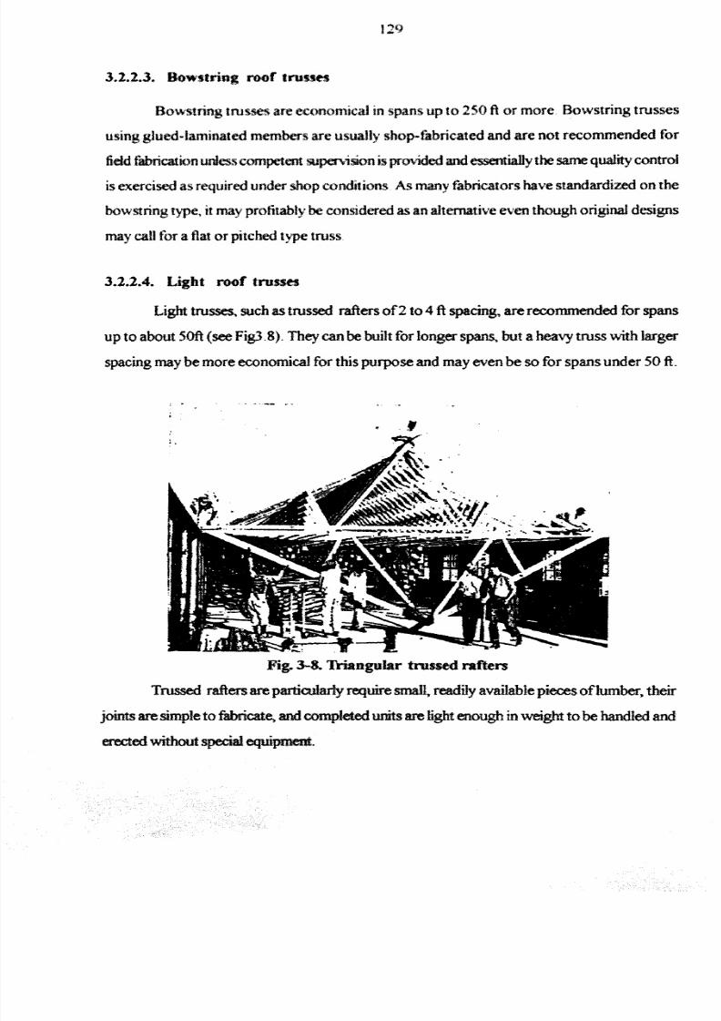
Light trusses, such as trussed rafters of2 to 4 ft sp acing , are recommended fo r sp an s
up to about 50ft (see Fig] .8). They can be built fo r longer sp ans, bu t a h eavy tru ss w ith larger
spacing may be more economical for this purpose and may even be so for spans under 50 ft .
,
Fig. 3-&. Triangular trossed rafters
Trussed raf te rs a re particu la rly requi re small, readily ava ilable p ieces of lumber, their
jo in ts a re simple to fabr icate, a n d completed units are light enough in weight to be handled and
erected without special equipment.
8/6/2019 Purlins and Truss
http://slidepdf.com/reader/full/purlins-and-truss 11/16
130
3.2.3. Truss proportions
3.2.3.1. Truss proportions
If econom y, deflection, and secondary stresses due to deflection are disregarded,
tr us ses may theore tically be built to a lmost any proportions. An unders tanding of the inter re la ted
factors that contribute to perform ance an d economy w ill aid the designer in selectin g the best
system.
3.2.3.2. Depth-to-span ratio
Certain ratios of effective depth to span are recommended as being satisfactory on
the basis of experience. The larger the span, the m ore desirable it is to use deeper trusses.
A lthoug h trusses o fless depth than these m ay be acceptab le, special attention should then b e
g iven to the possib ility o f g reate r def lection and seconda ry s tr es ses. Deflection in trus ses o fle ss -
than-average depth m ay be held to a m inim um by the follow ing practices: (1 )conservative
design,(2) the use o f low or interm ediate grad es of m aterial, (3) the use of a m inim um number
o f ch ord sp lic es (b y emplo yin g th e lo ng est a vailab le len gth s), (4 ) th e u se o f fasten in gs w ith th e
sm allest deform ation, and (5) the use of as few panels as possible. Stiffer m em bers are alsoo btain ed , an d th erefo re less d efle ctio n fo r a g iv en lo ad .
It is recommended that the top chord of a bow string truss be fabricated w ith a radius
abou t eq ual to the span. T he suggested effective depth-to-sp an ratio is betw een 1:6 and 1 :8. A
rad iu s eq ual to th e sp an w ill g iv e a ratio slig htly larg er th an th e su gg ested m in imum .
For pitched trusses, an effective depth-to-span ratio between 1:5 and 1:6 is
recommended, and a m inim um of not less than 1:7 unless special consideration is given to
deflection. M uch deeper trusses may be used for the sake of appearance, such as for the
s te ep ly p itc hed roofs popula r in chu rche s.
F or flat tru sses, a m in imum dep th -to -sp an ratio b etw ee n 1 :8 an d 1 : lO i s rec ommende d,
the deeper trusses b eing preferred fo r the lon ger sp ans. R oofs should have a m inim um slope o f
V4in . p er ft fo r p ro per d rain ag e, alth ou gh steep er slo pes are o ften d esirab le . F lat ro ofs w ith n o
slope for drianage are not recommended unless provision is m ade in the design for possible
accumulation of w ater due to a stopped drain or natural deflection. D rains on flat roo fs should
be located at the low points. These are at the center of the span if the truss is built flat.
Inlo ng er sp an s, seco nd ary d eflectio n stresse s a re p ro bab ly more impo rtan t. As these
stl:~ ses are not capable of ex act computatio n, the larger depth-to-span ratios should be used
for trus ses employing such spans . Deflection off ree- span trusses is usually we ll w ith in accep table

8/6/2019 Purlins and Truss
http://slidepdf.com/reader/full/purlins-and-truss 12/16
131
lim its, ev en th at fo r p laster, b ut c are sh ou ld b e ta ken to see th at th e n atu ral d efle ctio n does n ot
in te rfere wi th aux il ia ry f raming . Suspended ceil ingsa re o ften des irab le . Ample c learance shou ld
be provided betw een trusses and so-called nonbearing partitions or plate glass w indow s.
P ro visio n sh ou ld a lso b e mad e fo r ad ju stmen t in th e lev el o f th e h in gers ifthere i s a possibi li ty
th at d ef le ction may in te rf ere w ith th e p rope r ope ra tion o f tru ss- su spended doo rs o r mach inery .
3.2.3.3. Number ofpanels
It is desirable to use as few truss panels as the use of reasonable m em ber sizes w ill
allow This practice will mean fewer membe rs to handle , fewe r jo in ts to fabric ate and a ssemble ,
a nd theo re tic ally imp roved per fo rmance. The number o f panels u sually s hould be dete rmined
by reasonable top-chord sizes rather than by any fixed form ula. For m aterail of2 to 4 in.
th ick ness, d esirab le p an el len gth w ill u su ally b e in th e ran ge o f 6 to 1 0ft. Thu s, a symmetrical
truss of3 0 ft sp an wou ld p ro ba bly h av e fo ur p an els whereas a 4 0 ft tru ss might have e ith er four
or six, and an 80 ft tru ss eig ht o r te n.
System s for P itched Trusses
Bowstring trusses
, .
Pit<:htd trussesf
Figure 3-9. Truss types and web-member systems.

8/6/2019 Purlins and Truss
http://slidepdf.com/reader/full/purlins-and-truss 13/16
132
3.2.4. Roof construction systems
On ly tw o b asic sy stem s o f roo f co nstru ctio n need b e con sidered in truss d esign . O n e
app lie s rooflo ad s to th e tr us s only a t th e panel poin ts ; th e o ther app lie s t hem e ith er con tinuous ly ,
a s w ith p la nk ro ofin g; o r a t in te rv als a lo ng th e to p, a sw i th jo in ts. The fo rmer sy stem p rodu ce s
o nly d irect stress in th e cho rd member; th e latter in tro du ces ben din g as w ell as direct stress.
In term s oflum ber alone, joints closely spaced along the chords or purlins placed at
and betw een panel points are m ore econom ical than purlins placed only at the panel points
b eca use th e la tter re qu ire h eav ie r p la nk ro ofin g o r ra fte rs a nd sh ea th in g. Howev er, la bo r c osts
are less if purlins and planking are used instead of closely spaced joists because there are
few er p ieces to h an dle and few er po ints at w hich the plank in g must be n ailed . T hick p lan ks o f
th e lig hte r sp ec ies o f wood, w ith sp ecia l to ngue s a nd g ro ov es, a re sometimes a pp lie d d irec tly
to the top chords in palce of joists or purlins. T hey are probably the least expensive to install
from a la bo r sta ndpo in t. P lan k ro ofin g a nd h ea vy purlin s o ffe r imp ro ve d fire re sistan ce, a s d o
all h eav y tru ss members comp ared to th inn er o r lig hter m embers. P urlin s used at pan el po in ts
do not introduce appreciable bending in the top chord. T hey m ay therefore be desirable as a
means o f keeping cho rd s iz es r es onab le , p ar tic ula rly for la rg er s pans, h eavie r lo ad ings , a nd for
f ia t, p itc hed, o r o th er s tr aight- chord tr us se s.
3.2.5. Roof -truss spacing
There are n o fix ed ru les fo r spacing tru sses in bu ild in gs. S pacin g may b e affected b y
roo ff raming, wa ll c on str uc tion, s iz e o f ma te ria l a va ila ble , lo ad ing conditions , a nd the column
sp acin g d esire d fo r ma terial h an dlin g o r tra ffic . In g eneral, th e g reater th e spacing , th e more
e comnomical th e con stru ction., a nd the longer th e span, th e more desir ab le th e g re ate r s pa cing.
Spacing lim its are set by the purlin or joists sizes available for fram ing betw een trusses.
S pacin g is o ften more o r less arb itrarily ch osen becau se o f its suitability fo r a p articular roo f
and w all construction or building function. F or example, if m asonry w alls are used, a truss
s pa cing is f re quen tly se le cted th at will f it th e p ila ste r s pa cing requ ir ed for th e la te ra l s uppo rt o f
th e w alls. If ro of sh eathin g material is to be ap plied d irectly to th e tru sses w ith ou t au xiliary
fram in g-in o rder to sav e th e lab or of p lacing th e pu rlins-the sp acin g m ig ht vary from, say , 2 ft
w ith I-in. sheathing, to 7 to 9 ft, w ith 2 in. plank, or to still greater dim ensions w ith heavier
plank. Ifo is ts o r pur lin s a re u sed between trus se s, th e s pacing might be dete rmind by economical
and available joints sizes although common usage w ould probably call for a spacing in the
range of 14 to 20 ft. Ifspacing ex ceeds 20 ft, th e av ailability o f req uired sizes an d len gth s
shou ld def in it ely be cons idered . Ifsp acin g is d esire d th at is g rea te r th an th at su ita ble fo r sawed
pur lin s, e ith er g lu ed -laminated purlin s o r tru ss ed pur lin s may be u sed in ste ad .

8/6/2019 Purlins and Truss
http://slidepdf.com/reader/full/purlins-and-truss 14/16
133
3.2.6. Purlins truss
Ifth e spacing o f tr us se s requ ire s lo ng er purlin s th an a re commerc ia lly avilable , p urlin s
tru sse s a re fre qu ently use d. The ir d esig n is sim ila r to tha t o f a ny simple tru ss. If p urlin tru sse s
are inclined from the vertical, that is , if they do not have their top and bottom , chords in the
sam e vertical plane, as when used on pitched trusses, it is im portant that bracing be provided
to keep the bottom chords in proper position.
3.2.7. Roof -truss bracing andanchorage
B racing and anchorage is necessary to hold trusses and truss members in proper
position so that they can resist vertical loads as w ell as lateral loads such as w ind, im pact, or
earthquake. A lthough roof fram ing w ill usually serve as lateral bracing for the top-chord
m em bers, it is im portant that adeq uate lateral supports be provided for the bottom -chord
m embers (seeF ig3.I 0), and also that consideration be given to the possible need for vertical-
sw ay bracing betw een top and bottom chords of adjacent trusses (see (F ig. 3. 11). H orizontal
c ro ss -b racin g is some times requ ir ed in th e p lane o f e ith er th e to p and bottom cho rd , p articula rly
in lo ng b uild in gs in whic h the d ia ph ra gm actio n o fth e ro offraming is no t a de qua te for e nd -wall
forces, or in w hich side-w all loads are resisted by end w alls or interm ediate bracing such as
cross w alls. T he latter situation arises if each truss and its support are not designed as a bent
to re sist th e late ra l lo ad .
T ru sse s must b e se cu re ly a nch ore d to pro pe rly de sign ed walls o r c olumn s and column s
in tum ancho re d to fo und ation s. Unle ss some othe r p rov isio n mad e fo r la teral lo ad s o n th e side
w alls and on the vertical projection of the roof-such as for diaphragm action in w alls and roof
sheathing-lateral resistance should be provided in the colum n m em bers by m eans of knee
braces or fixity at the column base. T he bracing should be designed and detailed w ith the sam e
care as the truss itself and not left to the judgm ent of the contractor.
T he bracing req uirem ents here suggested are m inim um s, and are not dependent on
actual lateral-load analysis or on local code req uirem ents. V ertical cross-bracing should be
in sta lled at th e b ottom ch ord a t th e loc ation o f th e v ertic al b ra cin g and b e co ntinu ou s from end

8/6/2019 Purlins and Truss
http://slidepdf.com/reader/full/purlins-and-truss 15/16
134
Roof Trusses
Fig. 3-10. Bottom latral bracing
If required, bottom lateral bracing usually appears in same sections as vertical sway
bracing. Members are fastened to truss or to horizontal runners and plate. Wood members
may be used, or steel rods. Hangers may be used from roof framing to eliminate sag in
members. Continuous runners run foil length of building . They may be nearly square, solid
members or built up in "T" ,"U", or ''I" shapes. They are fasten to bottom chord or web
members near chord. Built-up runners should be spiked and bolted together. For top lateral
bracing, diagonal roof sheathing well applied to joists or purlins-with these in turn securely
fastened to the truss-is usually sufficient. Sometimes., however, bracing similar to bottom
lateral bracing should be applied in the plane of the top chords.
Design Conditions
Fig. 3-11. Vertical sway bracing and wall-and-column bracing
Vertical sway bracing is to be used in end section as a minimum, possibly two sections at
each end and near midspan for long buildings. It consists of wood members or steel rods
fastened to the truss, roof structure, or runners. Column-and-wall bracing should be used
where possible. it may consist of diagonal sheathing with studs or girts, let-in braing, or
cross-bracing. Crossing may be of wood members or steel rods.

8/6/2019 Purlins and Truss
http://slidepdf.com/reader/full/purlins-and-truss 16/16
I l S
wall to end wall Such struts and cross-bracing should be adeq uate for a m inimum horizontal
compresson load of 10 percent of the bottom -chord stress The 10 percent may be distributed
in ratio to the number oflines of cross-bracing and proportion to th e number of cross-braces
in each line if additiona l bays in exces s o f th e minimum are provided. Pos it ive fasten ings , such
as bolts, lag screws, or timber connectors, shou ld be provided. Special precautio ns should be
tak en to provide adequate b racing of trusses du ring and after erection and un til th e permanent
b rac ing system and roof shea th ing a re in sta lled
Illustrative ex ample of d esign of roof trusses are shown in Design P roject.