PURE Ceramic Implant System Basic information on the ... · Technical Information. Straumann® PURE...
48
Technical Information Straumann® PURE Ceramic Implant System Basic information on the surgical and prosthetic procedures
Transcript of PURE Ceramic Implant System Basic information on the ... · Technical Information. Straumann® PURE...
Technical Information
Straumann® PURE Ceramic Implant System
Basic information on the surgical and prosthetic procedures
490.074_SbS_2pc_Pure.indd 1 23/05/2017 16:29

About this guide
This surgical and prosthetic procedure describes the steps required for implantation and res-toration of the Straumann® PURE Ceramic Implant System. The Straumann® PURE Ceramic Implant System is recommended for use only by clinicians with advanced surgical skills. It is assumed that the user is familiar with placing dental implants. Not all detailed information will be found in this guide. Reference to existing Straumann procedure manuals will be made throughout this document.
490.074_SbS_2pc_Pure.indd 2 23/05/2017 16:29
1
Contents
Prod
uct r
efer
ence
list
Tr
oubl
esho
otin
gAf
terc
are
and
clea
ning
Pr
osth
etic
pro
cedu
re M
onot
ype
Pros
thet
ic p
roce
dure
Surg
ical
pro
cedu
reIn
dica
tions
and
cont
rain
dica
tions
Feat
ures
and
ben
efits
PURE
Cer
amic
Impl
ant S
yste
m
1. Straumann® PURE Ceramic Implant System 21.1 Straumann® PURE Ceramic Implant 2
1.2 Straumann® PURE Ceramic Implant Monotype 3
2. Implant features and benefits 42.1 Material 4
2.2 Surface 4
2.3 Design 5
3. Indications and contraindications 63.1 Intended use 6
3.2 Indications 6
3.3 Contraindications 6
4. Surgical procedure for Straumann® PURE Ceramic Implant System 74.1 Preoperative planning 7
4.2 Basic implant bed preparation 11
4.3 Fine implant bed preparation 14
4.4 Implant insertion 15
5. Prosthetic procedure for Straumann® PURE Ceramic Implant 215.1 Healing phase 21
5.2 Healing components 21
5.3 Submucosal healing with Closure Caps 22
5.4 Transmucosal healing with Healing Caps 23
5.5 Impression taking 24
5.6 Straumann® Temporary Abutment VITA CAD-Temp® 27
5.7 Creation and fixation of the final restoration 31
6. Prosthetic procedure for Straumann® PURE Ceramic Implant Monotype 326.1 Protection during the healing phase 32
6.2 Impression taking 35
6.3 Temporization 37
6.4 Creation and cementation of the final restoration 39
7. Aftercare and cleaning of Straumann® PURE Ceramic Implant 41
8. Troubleshooting 418.1 Implant removal 41
8.2 Fracture of the abutment (Straumann® PURE Ceramic Implant Monotype) 41
9. Product reference list 429.1 Straumann® PURE Ceramic Implant 42
9.2 Straumann® PURE Ceramic Implant Monotype 43
490.074_SbS_2pc_Pure.indd 1 23/05/2017 16:29
2
1. Straumann® PURE Ceramic Implant System
The Straumann® PURE Ceramic Implant System is available as monotype design in the endosteal diameters of 4.1 mm and 3.3 mm and as two-piece design in the endosteal diameter of 4.1 mm.
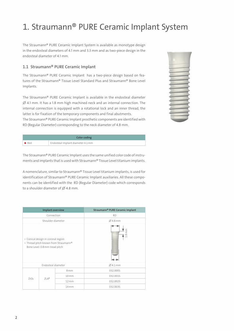
1.1 Straumann® PURE Ceramic Implant
The Straumann® PURE Ceramic Implant has a two-piece design based on fea-tures of the Straumann® Tissue Level Standard Plus and Straumann® Bone Level Implants.
The Straumann® PURE Ceramic Implant is available in the endosteal diameter ∅ 4.1 mm. It has a 1.8 mm high machined neck and an internal connection. The internal connection is equipped with a rotational lock and an inner thread, the latter is for fixation of the temporary components and final abutments. The Straumann® PURE Ceramic Implant prosthetic components are identified with RD (Regular Diameter) corresponding to the neck diameter of 4.8 mm.
Implant overview Straumann® PURE Ceramic Implant
Connection RD
Shoulder diameter ∅ 4.8 mm
▪ Conical design in coronal region ▪ Thread pitch known from Straumann® Bone Level: 0.8 mm tread pitch
1.8
mm
Endosteal diameter ∅ 4.1 mm
ZrO2 ZLA®
8 mm 032.000S
10 mm 032.001S
12 mm 032.002S
14 mm 032.003S
Color coding
Red Endosteal implant diameter 4.1 mm
The Straumann® PURE Ceramic Implant uses the same unified color code of instru-ments and implants that is used with Straumann® Tissue Level titanium implants.
A nomenclature, similar to Straumann® Tissue Level titanium implants, is used for identification of Straumann® PURE Ceramic Implant auxiliaries. All these compo-nents can be identified with the RD (Regular Diameter) code which corresponds to a shoulder diameter of ∅ 4.8 mm.
490.074_SbS_2pc_Pure.indd 2 23/05/2017 16:29
3
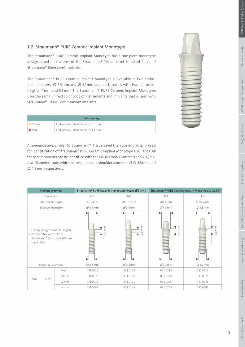
1.2 Straumann® PURE Ceramic Implant Monotype
The Straumann® PURE Ceramic Implant Monotype has a one-piece monotype design based on features of the Straumann® Tissue Level Standard Plus and Straumann® Bone Level Implants.
The Straumann® PURE Ceramic Implant Monotype is available in two endos-teal diameters, ∅ 3.3 mm and ∅ 4.1 mm, and each comes with two abutment heights, 4 mm and 5.5 mm. The Straumann® PURE Ceramic Implant Monotype uses the same unified color code of instruments and implants that is used with Straumann® Tissue Level titanium implants.
Color coding
Yellow Endosteal implant diameter 3.3 mm
Red Endosteal implant diameter 4.1 mm
A nomenclature, similar to Straumann® Tissue Level titanium implants, is used for identification of Straumann® PURE Ceramic Implant Monotype auxiliaries. All these components can be identified with the ND (Narrow Diameter) and RD (Reg-ular Diameter) code which corresponds to a shoulder diameter of ∅ 3.5 mm and ∅ 4.8 mm respectively.
Implant overview Straumann® PURE Ceramic Implant Monotype ∅ 3.3 ND Straumann® PURE Ceramic Implant Monotype ∅ 4.1 RD
Connection ND ND RD RD
Abutment height AH 4 mm AH 5.5 mm AH 4 mm AH 5.5 mm
Shoulder diameter ∅ 3.5 mm ∅ 3.5 mm ∅ 4.8 mm ∅ 4.8 mm
▪ Conical design in coronal region ▪ Thread pitch known from Straumann® Bone Level: 0.8 mm tread pitch
Endosteal diameter ∅ 3.3 mm ∅ 3.3 mm ∅ 4.1 mm ∅ 4.1 mm
ZrO2 ZLA®
8 mm 031.001S 031.011S 031.021S 031.031S
10 mm 031.002S 031.012S 031.022S 031.032S
12 mm 031.003S 031.013S 031.023S 031.033S
14 mm 031.004S 031.014S 031.024S 031.034S
1.8
mm
1.8
mm
1.8
mm
1.8
mm
Prod
uct r
efer
ence
list
Tr
oubl
esho
otin
gAf
terc
are
and
clea
ning
Pr
osth
etic
pro
cedu
re M
onot
ype
Pros
thet
ic p
roce
dure
Surg
ical
pro
cedu
reIn
dica
tions
and
cont
rain
dica
tions
Feat
ures
and
ben
efits
PURE
Cer
amic
Impl
ant S
yste
m
490.074_SbS_2pc_Pure.indd 3 23/05/2017 16:29
4
2.1 Material
The Straumann® PURE Ceramic Implant System is made from 100 % yttria-stabilized zirconia (Y-TZP). This ma-terial has been used for a long time in orthopedics with successful results.
2. Implant features and benefits
Property Unit Titanium grade 4 Y-TZP
Density g/cm3 4.5 6.05
Hardness HV 250 1100 – 1500
Strength MPa 680 (tensile) ≥ 1200 (4-point bending strength)
Mod. of elasticity GPa 110 200 – 220
WarningNo grinding of any part of the implant or implant abutment (Monotype) is allowed. Grinding can lead to mi-cro-cracks in the material which may result in a significant reduction of the implant strength.
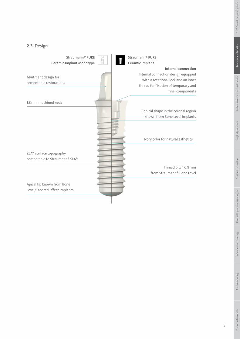
2.2 Surface
The Straumann® ZLA® surface features a topography characterized by macro- and micro-roughness to offer a structure for cell attachment. In preclinical studies, the ZLA® surface demonstrated similar healing patterns, healing times and osseointegration in terms of peri-implant bone density and bone-to-implant contact (BIC) as seen for the SLA® surface1,2.
50 µm 50 µm
ZLA® surface SLA® surface
1Gahlert M, Roehling S, Sprecher CM, Kniha H, Milz S, Bormann K (2012). Clin Oral Implants Res 23(3):281-286.2Gahlert M, Rohling S, Wieland M, Eichhorn S, Kuchenhoff H, Kniha H (2010). Clin Implant Dent Relat Res 12(4):297-305.
490.074_SbS_2pc_Pure.indd 4 23/05/2017 16:29
5
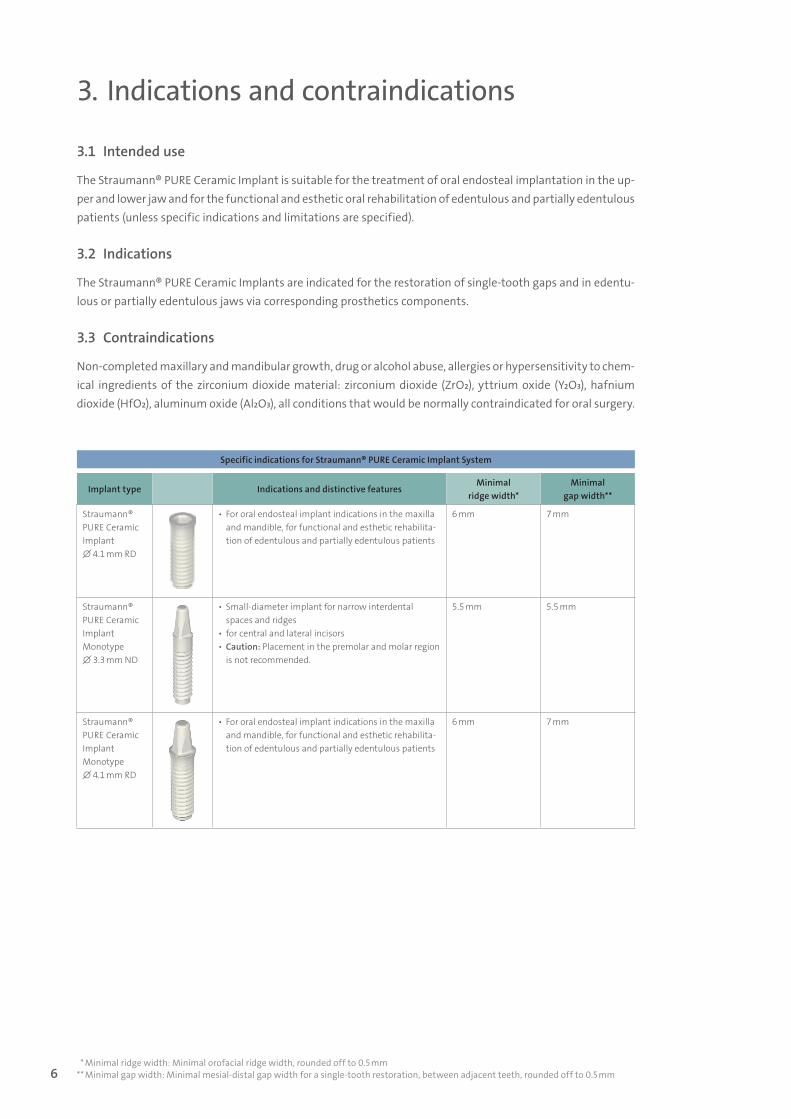
Abutment design for cementable restorations
1.8 mm machined neck
ZLA® surface topography comparable to Straumann® SLA®
Ivory color for natural esthetics
Conical shape in the coronal region known from Bone Level Implants
Thread pitch 0.8 mm from Straumann® Bone Level
Internal connectionInternal connection design equipped
with a rotational lock and an inner thread for fixation of temporary and
final components
Apical tip known from Bone Level/Tapered Effect Implants
2.3 Design
Prod
uct r
efer
ence
list
Tr
oubl
esho
otin
gAf
terc
are
and
clea
ning
Pr
osth
etic
pro
cedu
re M
onot
ype
Pros
thet
ic p
roce
dure
Surg
ical
pro
cedu
reIn
dica
tions
and
cont
rain
dica
tions
Feat
ures
and
ben
efits
PURE
Cer
amic
Impl
ant S
yste
m
Straumann® PURE Ceramic Implant Monotype
Straumann® PURE Ceramic Implant
490.074_SbS_2pc_Pure.indd 5 23/05/2017 16:29
6
3. Indications and contraindications
3.1 Intended use
The Straumann® PURE Ceramic Implant is suitable for the treatment of oral endosteal implantation in the up-per and lower jaw and for the functional and esthetic oral rehabilitation of edentulous and partially edentulous patients (unless specific indications and limitations are specified).
3.2 Indications
The Straumann® PURE Ceramic Implants are indicated for the restoration of single-tooth gaps and in edentu-lous or partially edentulous jaws via corresponding prosthetics components.
3.3 Contraindications
Non-completed maxillary and mandibular growth, drug or alcohol abuse, allergies or hypersensitivity to chem-ical ingredients of the zirconium dioxide material: zirconium dioxide (ZrO₂), yttrium oxide (Y₂O₃), hafnium dioxide (HfO₂), aluminum oxide (Al₂O₃), all conditions that would be normally contraindicated for oral surgery.
Specific indications for Straumann® PURE Ceramic Implant System
Implant type Indications and distinctive featuresMinimal
ridge width*Minimal
gap width**
Straumann® PURE Ceramic Implant∅ 4.1 mm RD
▪ For oral endosteal implant indications in the maxilla and mandible, for functional and esthetic rehabilita-tion of edentulous and partially edentulous patients
6 mm 7 mm
Straumann® PURE Ceramic Implant Monotype∅ 3.3 mm ND
▪ Small-diameter implant for narrow interdental spaces and ridges
▪ for central and lateral incisors ▪ Caution: Placement in the premolar and molar region is not recommended.
5.5 mm 5.5 mm
Straumann® PURE Ceramic Implant Monotype∅ 4.1 mm RD
▪ For oral endosteal implant indications in the maxilla and mandible, for functional and esthetic rehabilita-tion of edentulous and partially edentulous patients
6 mm 7 mm
* Minimal ridge width: Minimal orofacial ridge width, rounded off to 0.5 mm** Minimal gap width: Minimal mesial-distal gap width for a single-tooth restoration, between adjacent teeth, rounded off to 0.5 mm
490.074_SbS_2pc_Pure.indd 6 23/05/2017 16:29
7
4. Surgical procedure for Straumann® PURE Ceramic Implant System
The Straumann® PURE Ceramic Implant System can be placed with the existing Straumann® Surgical Cassette while using a very similar surgical procedure as the Bone Level surgical protocol. The workflow for the surgical procedure for the Straumann® PURE Ceramic Implant System includes 4 steps: Preoperative plan-ning, basic implant bed preparation, fine implant bed preparation and implant insertion.
4.1 Preoperative planning
For the preoperative planning, the implant position and the planning aids will provide all information required to determine the most suitable position for the implant and its prosthetic reconstruction. The design of the Straumann® PURE Ceramic Implant Monotype requires the planning of the implant placing to be very thorough and detailed. A prosthetic-driven planning is recommended and also particularly important for the Straumann® PURE Ceramic Implant Monotype as a perfect axis for implant insertion during implant bed preparation is crucial.
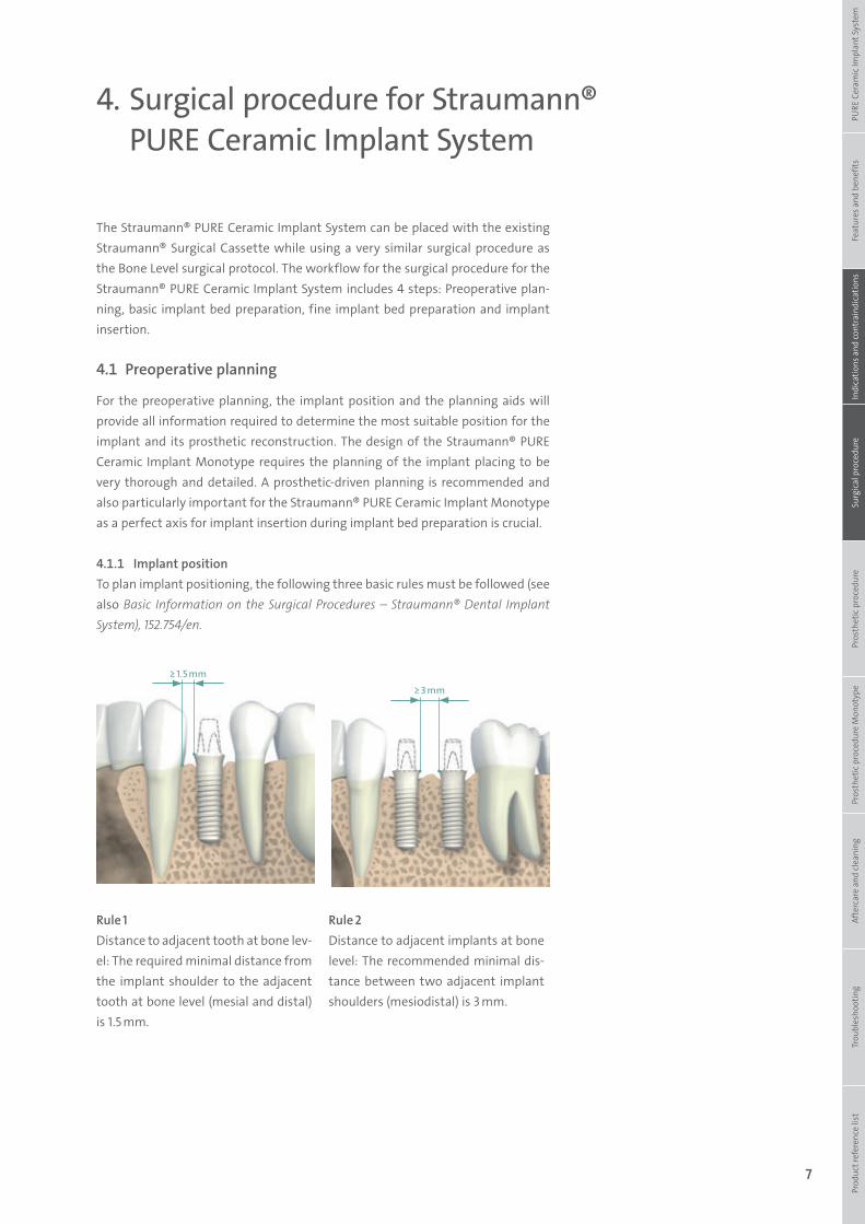
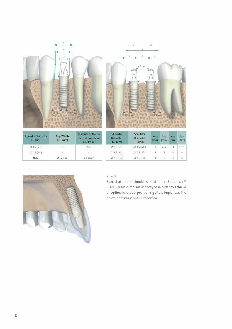
4.1.1 Implant positionTo plan implant positioning, the following three basic rules must be followed (see also Basic Information on the Surgical Procedures – Straumann® Dental Implant System), 152.754/en.
Rule 1Distance to adjacent tooth at bone lev-el: The required minimal distance from the implant shoulder to the adjacent tooth at bone level (mesial and distal) is 1.5 mm.
Rule 2Distance to adjacent implants at bone level: The recommended minimal dis-tance between two adjacent implant shoulders (mesiodistal) is 3 mm.
≥ 1.5 mm≥ 3 mm
Prod
uct r
efer
ence
list
Tr
oubl
esho
otin
gAf
terc
are
and
clea
ning
Pr
osth
etic
pro
cedu
re M
onot
ype
Pros
thet
ic p
roce
dure
Surg
ical
pro
cedu
reIn
dica
tions
and
cont
rain
dica
tions
Feat
ures
and
ben
efits
PURE
Cer
amic
Impl
ant S
yste
m
490.074_SbS_2pc_Pure.indd 7 23/05/2017 16:29
8
Shoulder DiameterD [mm]
Gap Width amin [mm]
Distance between teeth at bone level
bmin [mm]
∅ 3.5 (ND) 5.5 6.5
∅ 4.8 (RD) 7 8
Rule D + 2 mm D + 3 mm
Shoulder DiameterD1 [mm]
Shoulder DiameterD₂ [mm]
amin [mm]
bmin [mm]
cmin [mm]
Lmin [mm]
∅ 3.5 (ND) ∅ 3.5 (ND) 3 6.5 3 12.5
∅ 3.5 (ND) ∅ 4.8 (RD) 3 7 4 14
∅ 4.8 (RD) ∅ 4.8 (RD) 4 8 4 16
b
L
a
D1 D₂
cb
≥ 3 mm
a
D
≥ 1.5 mm ≥ 1.5 mm≥ 1.5 mm ≥ 1.5 mm
Rule 3Special attention should be paid to the Straumann® PURE Ceramic Implant Monotype in order to achieve an optimal orofacial positioning of the implant, as the abutments must not be modified.
490.074_SbS_2pc_Pure.indd 8 23/05/2017 16:29
9
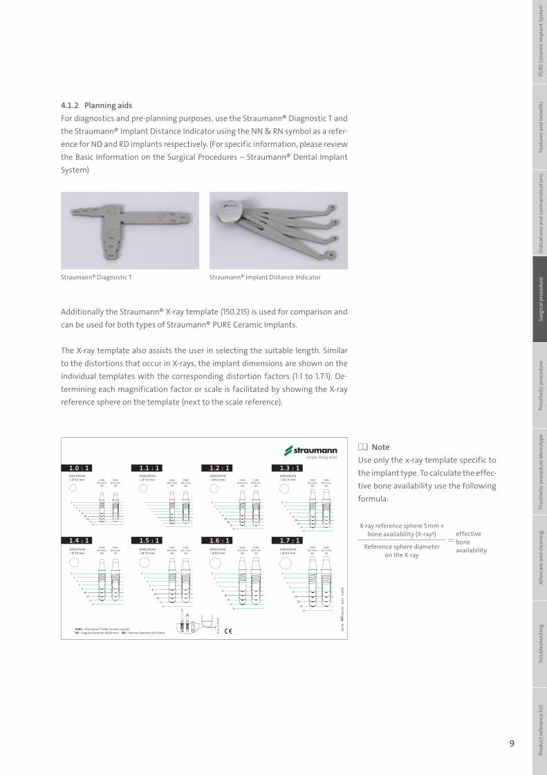
4.1.2 Planning aidsFor diagnostics and pre-planning purposes, use the Straumann® Diagnostic T and the Straumann® Implant Distance Indicator using the NN & RN symbol as a refer-ence for ND and RD implants respectively. (For specific information, please review the Basic Information on the Surgical Procedures – Straumann® Dental Implant System)
Additionally the Straumann® X-ray template (150.215) is used for comparison and can be used for both types of Straumann® PURE Ceramic Implants.
The X-ray template also assists the user in selecting the suitable length. Similar to the distortions that occur in X-rays, the implant dimensions are shown on the individual templates with the corresponding distortion factors (1:1 to 1.7:1). De-termining each magnification factor or scale is facilitated by showing the X-ray reference sphere on the template (next to the scale reference).
NoteUse only the x-ray template specific to the implant type. To calculate the effec-tive bone availability use the following formula:
Straumann® Diagnostic T Straumann® Implant Distance Indicator
PUREØ 3.3mm
ND
PUREØ 4.1 mm
RD
PUREØ 3.3mm
ND
PUREØ 4.1 mm
RD
PUREØ 3.3mm
ND
PUREØ 4.1 mm
RD
PUREØ 3.3mm
ND
PUREØ 4.1 mm
RD
PUREØ 3.3mm
ND
PUREØ 4.1 mm
RD
PUREØ 3.3mm
ND
PUREØ 4.1 mm
RD
PUREØ 3.3mm
ND
PUREØ 4.1 mm
RD
PUREØ 3.3mm
ND
PUREØ 4.1 mm
RD
(049.076V4) = Ø 5.0 mm
(049.076V4) = Ø 7.0 mm
(049.076V4) = Ø 7.5 mm
(049.076V4) = Ø 8.0 mm
(049.076V4) = Ø 8.5 mm
(049.076V4) = Ø 5.5 mm
(049.076V4) = Ø 6.0 mm
(049.076V4) = Ø 6.5 mm
1.0 : 1 1.1 : 1 1.2 : 1 1.3 : 1
1.4 : 1 1.5 : 1 1.6 : 1 1.7 : 1
02
46
810
1214
16
02
46
810
1214
16
0
2
4
6
8
10
12
14
16
0
2
4
6
8
10
12
14
16
0
2
4
6
8
10
12
14
16
02
46
810
1214
16
02
46
810
1214
16
max
. 0.4
mm
02/1
4
150.
215
B/
01
E10
913
PURE = Straumann® PURE Ceramic ImplantRD = Regular Diameter (ø 4.8 mm) ND = Narrow Diameter (ø 3.5 mm)
150.215.indd 6 25.02.14 07:50
X-ray reference sphere 5 mm × bone availability (X-ray²) effective
bone availabilityReference sphere diameter
on the X-ray
Prod
uct r
efer
ence
list
Tr
oubl
esho
otin
gAf
terc
are
and
clea
ning
Pr
osth
etic
pro
cedu
re M
onot
ype
Pros
thet
ic p
roce
dure
Surg
ical
pro
cedu
reIn
dica
tions
and
cont
rain
dica
tions
Feat
ures
and
ben
efits
PURE
Cer
amic
Impl
ant S
yste
m
490.074_SbS_2pc_Pure.indd 9 23/05/2017 16:29
10
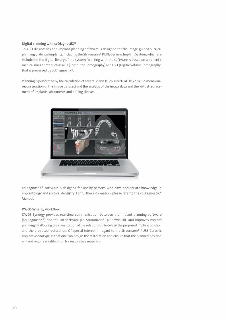
Digital planning with coDiagnostiX®This 3D diagnostics and implant planning software is designed for the image-guided surgical planning of dental implants, including the Straumann® PURE Ceramic Implant System, which are included in the digital library of the system. Working with the software is based on a patient’s medical image data such as a CT (Computed Tomography) and DVT (Digital Volume Tomography) that is processed by coDiagnostiX®.
Planning is performed by the calculation of several views (such as virtual OPG or a 3-dimensional reconstruction of the image dataset) and the analysis of the image data and the virtual replace-ment of implants, abutments and drilling sleeves.
coDiagnostiX® software is designed for use by persons who have appropriate knowledge in implantology and surgical dentistry. For further information, please refer to the coDiagnostiX® Manual.
DWOS Synergy workflow DWOS Synergy provides real-time communication between the implant planning software (coDiagnostiX®) and the lab software (i.e. Straumann®CARES®Visual) and improves implant planning by allowing the visualization of the relationship between the proposed implant position and the proposed restoration. Of special interest in regard to the Straumann® PURE Ceramic Implant Monotype, is that one can design the restoration and ensure that the planned position will not require modification for restorative materials.
490.074_SbS_2pc_Pure.indd 10 23/05/2017 16:29
11
4.2 Basic implant bed preparation
For preparing the implant bed the Straumann® Surgical Cassette is used.
4.2.1 Position indicatorFor the Straumann® PURE Ceramic Implant Monotype a specific new instrument is introduced in the surgical procedure, and it is used only during the basic implant bed preparation.
4.2.1.1 Intended useThe Straumann® PURE Ceramic Implant Monotype position indicators are instruments used to ensure correct positioning of the implant during implant bed preparation. The Straumann® PURE Ceramic Implant Monotype position indicators are made of titanium. They are delivered non-sterile and must be sterilized prior to use.
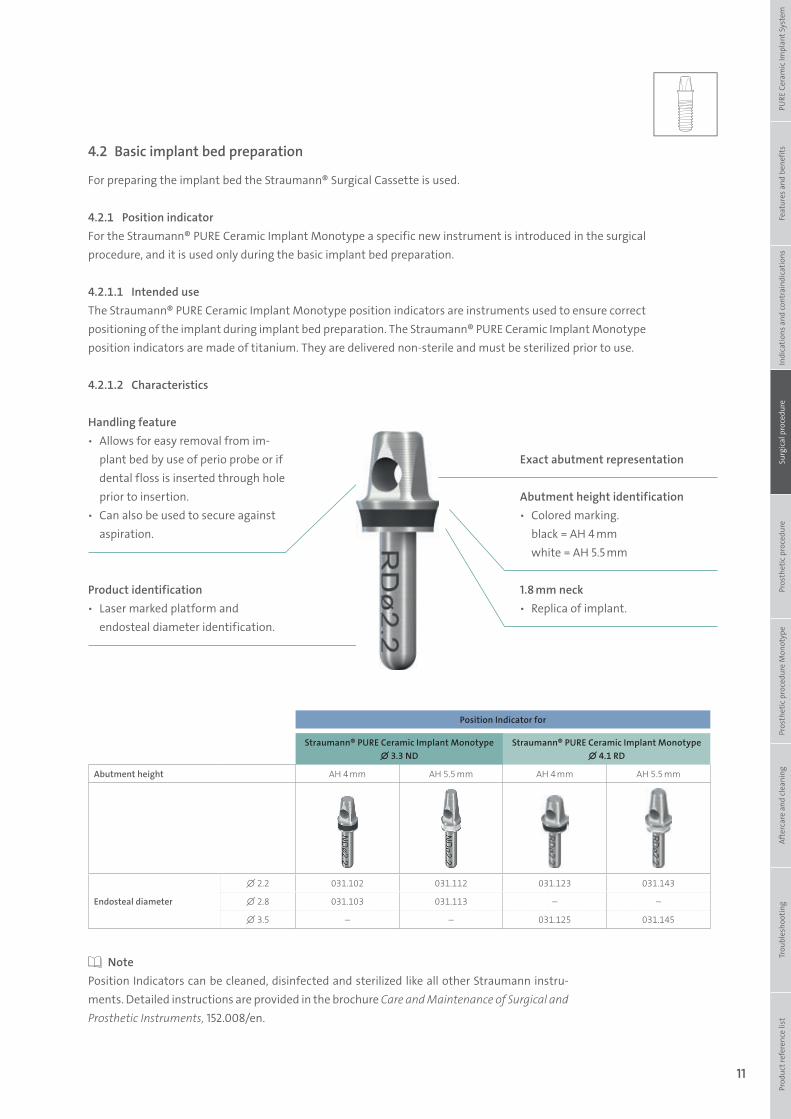
4.2.1.2 Characteristics
Handling feature ѹ Allows for easy removal from im-
plant bed by use of perio probe or if dental floss is inserted through hole prior to insertion.
ѹ Can also be used to secure against aspiration.
Exact abutment representation
Abutment height identification ѹ Colored marking.
black = AH 4 mm white = AH 5.5 mm
1.8 mm neck ѹ Replica of implant.
Product identification ѹ Laser marked platform and
endosteal diameter identification.
Position Indicator for
Straumann® PURE Ceramic Implant Monotype ∅ 3.3 ND
Straumann® PURE Ceramic Implant Monotype ∅ 4.1 RD
Abutment height AH 4 mm AH 5.5 mm AH 4 mm AH 5.5 mm
Endosteal diameter
∅ 2.2 031.102 031.112 031.123 031.143
∅ 2.8 031.103 031.113 – –
∅ 3.5 – – 031.125 031.145
NotePosition Indicators can be cleaned, disinfected and sterilized like all other Straumann instru-ments. Detailed instructions are provided in the brochure Care and Maintenance of Surgical and Prosthetic Instruments, 152.008/en.
Prod
uct r
efer
ence
list
Tr
oubl
esho
otin
gAf
terc
are
and
clea
ning
Pr
osth
etic
pro
cedu
re M
onot
ype
Pros
thet
ic p
roce
dure
Surg
ical
pro
cedu
reIn
dica
tions
and
cont
rain
dica
tions
Feat
ures
and
ben
efits
PURE
Cer
amic
Impl
ant S
yste
m
490.074_SbS_2pc_Pure.indd 11 23/05/2017 16:29
12
3
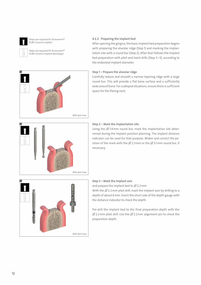
Steps are required for Straumann® PURE Ceramic Implant Monotype
4.2.2 Preparing the implant bedAfter opening the gingiva, the basic implant bed preparation begins with preparing the alveolar ridge (Step 1) and marking the implan-tation site with a round bur (Step 2). After that follows the implant bed preparation with pilot and twist drills (Step 3 – 5), according to the endosteal implant diameter.
Step 1 – Prepare the alveolar ridgeCarefully reduce and smooth a narrow tapering ridge with a large round bur. This will provide a flat bone surface and a sufficiently wide area of bone. For scalloped situations, ensure there is sufficient space for the flaring neck.
Step 2 – Mark the implantation siteUsing the ∅ 1.4 mm round bur, mark the implantation site deter-mined during the implant position planning. The implant distance indicator can be used for that purpose. Widen and correct the po-sition of the mark with the ∅ 2.3 mm or the ∅ 3.1 mm round bur, if necessary.
Step 3 – Mark the implant axis and prepare the implant bed to ∅ 2.2 mmWith the ∅ 2.2 mm pilot drill, mark the implant axis by drilling to a depth of about 6 mm. Insert the short side of the depth gauge with the distance indicator to check the depth.
Pre-drill the implant bed to the final preparation depth with the ∅ 2.2 mm pilot drill. Use the ∅ 2.2 mm alignment pin to check the preparation depth.
Steps are required for Straumann® PURE Ceramic Implant
1
2
800 rpm max
800 rpm max
800 rpm max
490.074_SbS_2pc_Pure.indd 12 23/05/2017 16:29
13
5
4
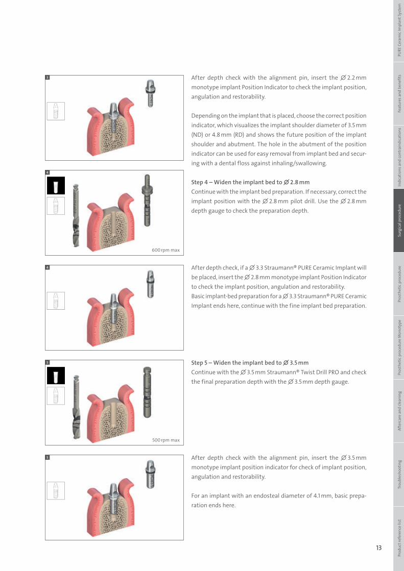
After depth check with the alignment pin, insert the ∅ 2.2 mm monotype implant Position Indicator to check the implant position, angulation and restorability.
Depending on the implant that is placed, choose the correct position indicator, which visualizes the implant shoulder diameter of 3.5 mm (ND) or 4.8 mm (RD) and shows the future position of the implant shoulder and abutment. The hole in the abutment of the position indicator can be used for easy removal from implant bed and secur-ing with a dental floss against inhaling/swallowing.
Step 4 – Widen the implant bed to ∅ 2.8 mmContinue with the implant bed preparation. If necessary, correct the implant position with the ∅ 2.8 mm pilot drill. Use the ∅ 2.8 mm depth gauge to check the preparation depth.
After depth check, if a ∅ 3.3 Straumann® PURE Ceramic Implant will be placed, insert the ∅ 2.8 mm monotype implant Position Indicator to check the implant position, angulation and restorability.Basic implant-bed preparation for a ∅ 3.3 Straumann® PURE Ceramic Implant ends here, continue with the fine implant bed preparation.
Step 5 – Widen the implant bed to ∅ 3.5 mmContinue with the ∅ 3.5 mm Straumann® Twist Drill PRO and check the final preparation depth with the ∅ 3.5 mm depth gauge.
After depth check with the alignment pin, insert the ∅ 3.5 mm monotype implant position indicator for check of implant position, angulation and restorability.
For an implant with an endosteal diameter of 4.1 mm, basic prepa-ration ends here.
3
4
5
600 rpm max
500 rpm max
Prod
uct r
efer
ence
list
Tr
oubl
esho
otin
gAf
terc
are
and
clea
ning
Pr
osth
etic
pro
cedu
re M
onot
ype
Pros
thet
ic p
roce
dure
Surg
ical
pro
cedu
reIn
dica
tions
and
cont
rain
dica
tions
Feat
ures
and
ben
efits
PURE
Cer
amic
Impl
ant S
yste
m
490.074_SbS_2pc_Pure.indd 13 23/05/2017 16:29
14
1
1
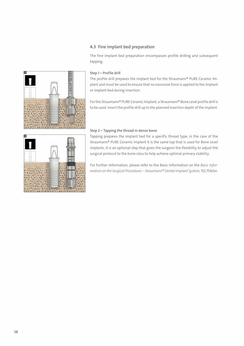
4.3 Fine implant bed preparation
The fine implant bed preparation encompasses profile drilling and subsequent tapping.
Step 1 – Profile drillThe profile drill prepares the implant bed for the Straumann® PURE Ceramic Im-plant and must be used to ensure that no excessive force is applied to the implant or implant bed during insertion.
For the Straumann® PURE Ceramic Implant, a Straumann® Bone Level profile drill is to be used. Insert the profile drill up to the planned insertion depth of the implant.
Step 2 – Tapping the thread in dense boneTapping prepares the implant bed for a specific thread type, in the case of the Straumann® PURE Ceramic Implant it is the same tap that is used for Bone Level implants. It is an optional step that gives the surgeon the flexibility to adjust the surgical protocol to the bone class to help achieve optimal primary stability.
For further information, please refer to the Basic Information on the Basic Infor-mation on the Surgical Procedures – Straumann® Dental Implant System, 152.754/en.
490.074_SbS_2pc_Pure.indd 14 23/05/2017 16:29
15
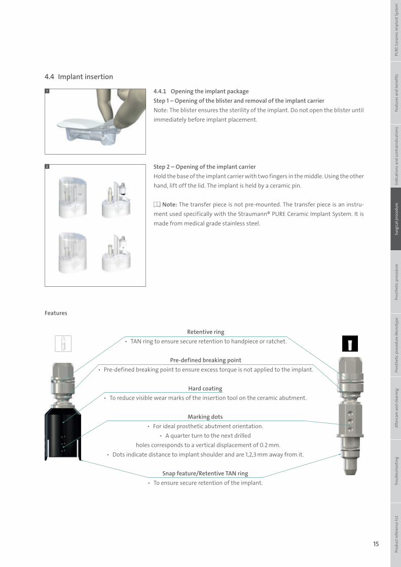
4.4.1 Opening the implant packageStep 1 – Opening of the blister and removal of the implant carrierNote: The blister ensures the sterility of the implant. Do not open the blister until immediately before implant placement.
Step 2 – Opening of the implant carrierHold the base of the implant carrier with two fingers in the middle. Using the other hand, lift off the lid. The implant is held by a ceramic pin.
Note: The transfer piece is not pre-mounted. The transfer piece is an instru-ment used specifically with the Straumann® PURE Ceramic Implant System. It is made from medical grade stainless steel.
1
2
Pre-defined breaking point ѹ Pre-defined breaking point to ensure excess torque is not applied to the implant.
Retentive ring ѹ TAN ring to ensure secure retention to handpiece or ratchet.
Hard coating ѹ To reduce visible wear marks of the insertion tool on the ceramic abutment.
Snap feature/Retentive TAN ring ѹ To ensure secure retention of the implant.
Marking dots ѹ For ideal prosthetic abutment orientation.
ѹ A quarter turn to the next drilled holes corresponds to a vertical displacement of 0.2 mm.
ѹ Dots indicate distance to implant shoulder and are 1,2,3 mm away from it.
Features
4.4 Implant insertion
Prod
uct r
efer
ence
list
Tr
oubl
esho
otin
gAf
terc
are
and
clea
ning
Pr
osth
etic
pro
cedu
re M
onot
ype
Pros
thet
ic p
roce
dure
Surg
ical
pro
cedu
reIn
dica
tions
and
cont
rain
dica
tions
Feat
ures
and
ben
efits
PURE
Cer
amic
Impl
ant S
yste
m
490.074_SbS_2pc_Pure.indd 15 23/05/2017 16:29
16
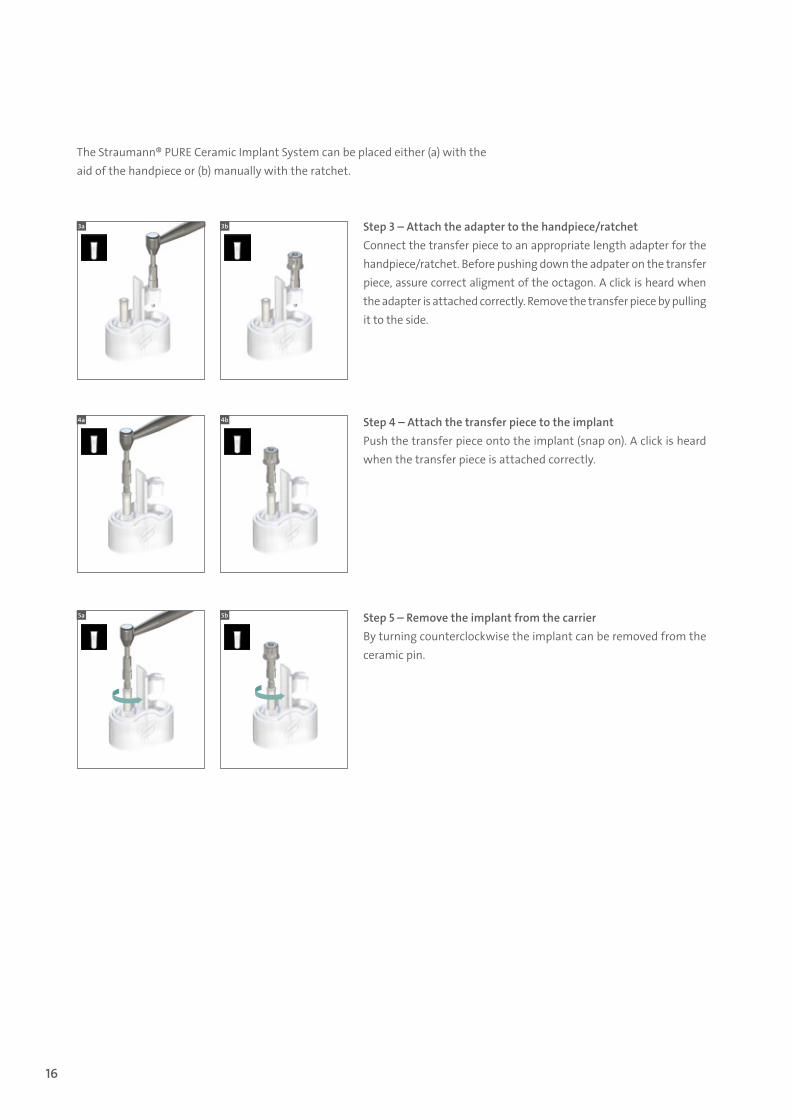
The Straumann® PURE Ceramic Implant System can be placed either (a) with the aid of the handpiece or (b) manually with the ratchet.
Step 3 – Attach the adapter to the handpiece/ratchetConnect the transfer piece to an appropriate length adapter for the handpiece/ratchet. Before pushing down the adpater on the transfer piece, assure correct aligment of the octagon. A click is heard when the adapter is attached correctly. Remove the transfer piece by pulling it to the side.
Step 4 – Attach the transfer piece to the implantPush the transfer piece onto the implant (snap on). A click is heard when the transfer piece is attached correctly.
Step 5 – Remove the implant from the carrierBy turning counterclockwise the implant can be removed from the ceramic pin.
3a 3b
4a 4b
5a 5b
490.074_SbS_2pc_Pure.indd 16 23/05/2017 16:29
17
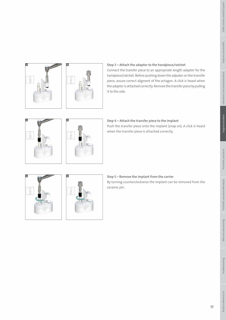
Step 3 – Attach the adapter to the handpiece/ratchetConnect the transfer piece to an appropriate length adapter for the handpiece/ratchet. Before pushing down the adpater on the transfer piece, assure correct aligment of the octagon. A click is heard when the adapter is attached correctly. Remove the transfer piece by pulling it to the side.
Step 4 – Attach the transfer piece to the implantPush the transfer piece onto the implant (snap on). A click is heard when the transfer piece is attached correctly.
Step 5 – Remove the implant from the carrierBy turning counterclockwise the implant can be removed from the ceramic pin.
3a 3b
4a 4b
5a 5b
Prod
uct r
efer
ence
list
Tr
oubl
esho
otin
gAf
terc
are
and
clea
ning
Pr
osth
etic
pro
cedu
re M
onot
ype
Pros
thet
ic p
roce
dure
Surg
ical
pro
cedu
reIn
dica
tions
and
cont
rain
dica
tions
Feat
ures
and
ben
efits
PURE
Cer
amic
Impl
ant S
yste
m
490.074_SbS_2pc_Pure.indd 17 23/05/2017 16:29
18
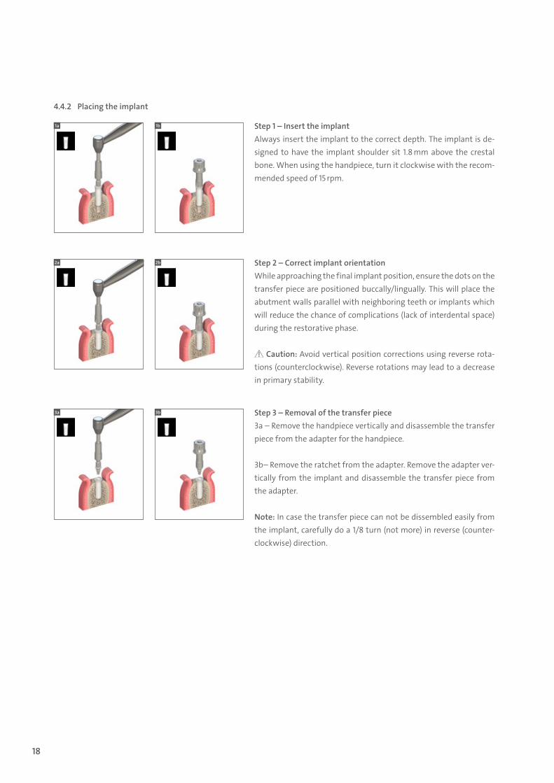
4.4.2 Placing the implant
Step 1 – Insert the implantAlways insert the implant to the correct depth. The implant is de-signed to have the implant shoulder sit 1.8 mm above the crestal bone. When using the handpiece, turn it clockwise with the recom-mended speed of 15 rpm.
Step 2 – Correct implant orientationWhile approaching the final implant position, ensure the dots on the transfer piece are positioned buccally/lingually. This will place the abutment walls parallel with neighboring teeth or implants which will reduce the chance of complications (lack of interdental space) during the restorative phase.
Caution: Avoid vertical position corrections using reverse rota-tions (counterclockwise). Reverse rotations may lead to a decrease in primary stability.
Step 3 – Removal of the transfer piece3a – Remove the handpiece vertically and disassemble the transfer piece from the adapter for the handpiece.
3b– Remove the ratchet from the adapter. Remove the adapter ver-tically from the implant and disassemble the transfer piece from the adapter.
Note: In case the transfer piece can not be dissembled easily from the implant, carefully do a 1/8 turn (not more) in reverse (counter-clockwise) direction.
1a
2a
3a
1b
2b
3b
490.074_SbS_2pc_Pure.indd 18 23/05/2017 16:29
19
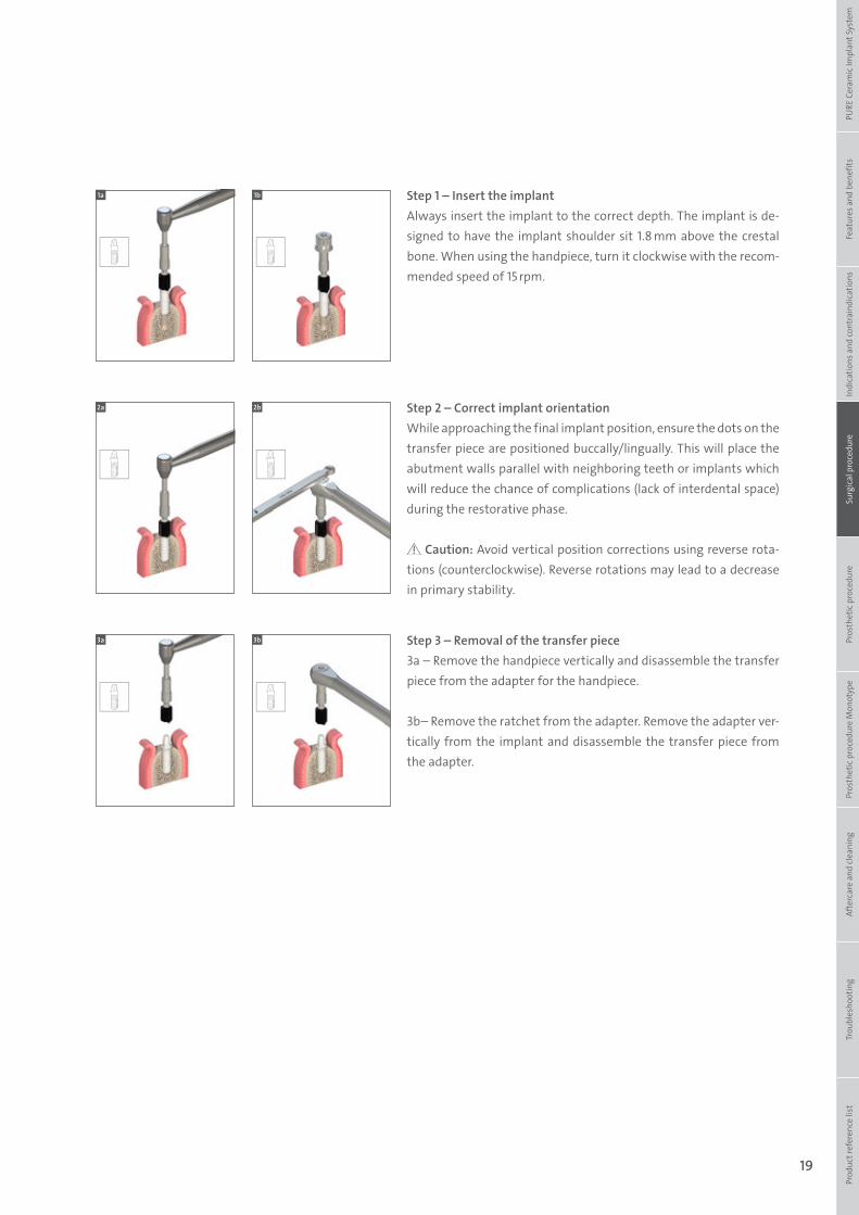
Step 1 – Insert the implantAlways insert the implant to the correct depth. The implant is de-signed to have the implant shoulder sit 1.8 mm above the crestal bone. When using the handpiece, turn it clockwise with the recom-mended speed of 15 rpm.
Step 2 – Correct implant orientationWhile approaching the final implant position, ensure the dots on the transfer piece are positioned buccally/lingually. This will place the abutment walls parallel with neighboring teeth or implants which will reduce the chance of complications (lack of interdental space) during the restorative phase.
Caution: Avoid vertical position corrections using reverse rota-tions (counterclockwise). Reverse rotations may lead to a decrease in primary stability.
Step 3 – Removal of the transfer piece3a – Remove the handpiece vertically and disassemble the transfer piece from the adapter for the handpiece.
3b– Remove the ratchet from the adapter. Remove the adapter ver-tically from the implant and disassemble the transfer piece from the adapter.
1a
2a
3a
1b
2b
3b
Prod
uct r
efer
ence
list
Tr
oubl
esho
otin
gAf
terc
are
and
clea
ning
Pr
osth
etic
pro
cedu
re M
onot
ype
Pros
thet
ic p
roce
dure
Surg
ical
pro
cedu
reIn
dica
tions
and
cont
rain
dica
tions
Feat
ures
and
ben
efits
PURE
Cer
amic
Impl
ant S
yste
m
490.074_SbS_2pc_Pure.indd 19 23/05/2017 16:29
20
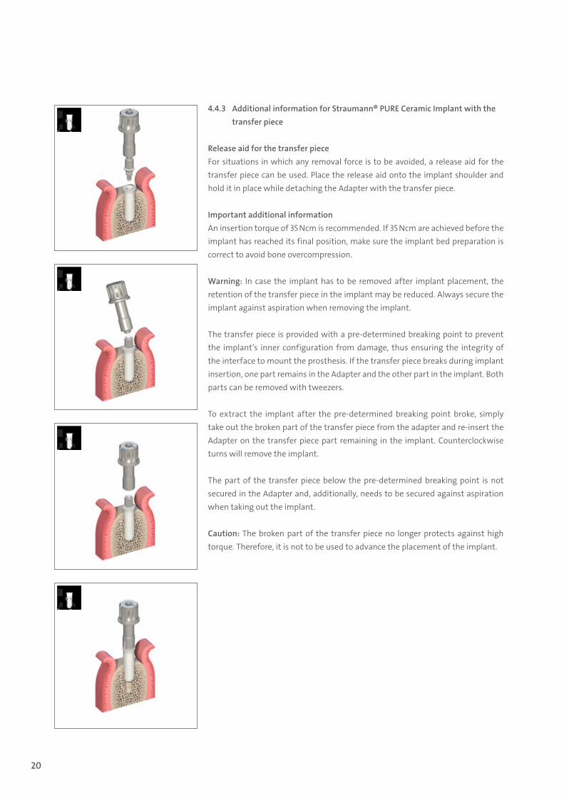
4.4.3 Additional information for Straumann® PURE Ceramic Implant with the transfer piece
Release aid for the transfer pieceFor situations in which any removal force is to be avoided, a release aid for the transfer piece can be used. Place the release aid onto the implant shoulder and hold it in place while detaching the Adapter with the transfer piece.
Important additional information An insertion torque of 35 Ncm is recommended. If 35 Ncm are achieved before the implant has reached its final position, make sure the implant bed preparation is correct to avoid bone overcompression.
Warning: In case the implant has to be removed after implant placement, the retention of the transfer piece in the implant may be reduced. Always secure the implant against aspiration when removing the implant.
The transfer piece is provided with a pre-determined breaking point to prevent the implant’s inner configuration from damage, thus ensuring the integrity of the interface to mount the prosthesis. If the transfer piece breaks during implant insertion, one part remains in the Adapter and the other part in the implant. Both parts can be removed with tweezers.
To extract the implant after the pre-determined breaking point broke, simply take out the broken part of the transfer piece from the adapter and re-insert the Adapter on the transfer piece part remaining in the implant. Counterclockwise turns will remove the implant.
The part of the transfer piece below the pre-determined breaking point is not secured in the Adapter and, additionally, needs to be secured against aspiration when taking out the implant.
Caution: The broken part of the transfer piece no longer protects against high torque. Therefore, it is not to be used to advance the placement of the implant.
490.074_SbS_2pc_Pure.indd 20 23/05/2017 16:29
21
5. Prosthetic procedure for Straumann® PURE Ceramic Implant
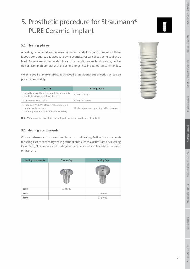
5.1 Healing phase
A healing period of at least 6 weeks is recommended for conditions where there is good bone quality and adequate bone quantity. For cancellous bone quality, at least 12 weeks are recommended. For all other conditions, such as bone augmenta-tion or incomplete contact with the bone, a longer healing period is recommended.
When a good primary stability is achieved, a provisional out of occlusion can be placed immediately.
Situation Healing phase
▪ Good bone quality and adequate bone quantity ▪ Implants with a diameter of 4.1 mm
At least 6 weeks
▪ Cancellous bone quality At least 12 weeks
▪ Straumann® ZLA® surface is not completely in contact with the bone
▪ Bone augmentation measures are necessaryHealing phase corresponding to the situation
5.2 Healing components
Choose between a submucosal and transmucosal healing. Both options are possi-ble using a set of secondary healing components such as Closure Caps and Healing Caps. Both, Closure Caps and Healing Caps are delivered sterile and are made out of titanium.
Healing components Closure Cap Healing Cap
0 mm 032.030S
2 mm 032.032S
3 mm 032.033S
Note: Micro-movements disturb osseointegration and can lead to loss of implants.
Prod
uct r
efer
ence
list
Tr
oubl
esho
otin
gAf
terc
are
and
clea
ning
Pr
osth
etic
pro
cedu
re M
onot
ype
Pros
thet
ic p
roce
dure
Surg
ical
pro
cedu
reIn
dica
tions
and
cont
rain
dica
tions
Feat
ures
and
ben
efits
PURE
Cer
amic
Impl
ant S
yste
m
490.074_SbS_2pc_Pure.indd 21 23/05/2017 16:29
22
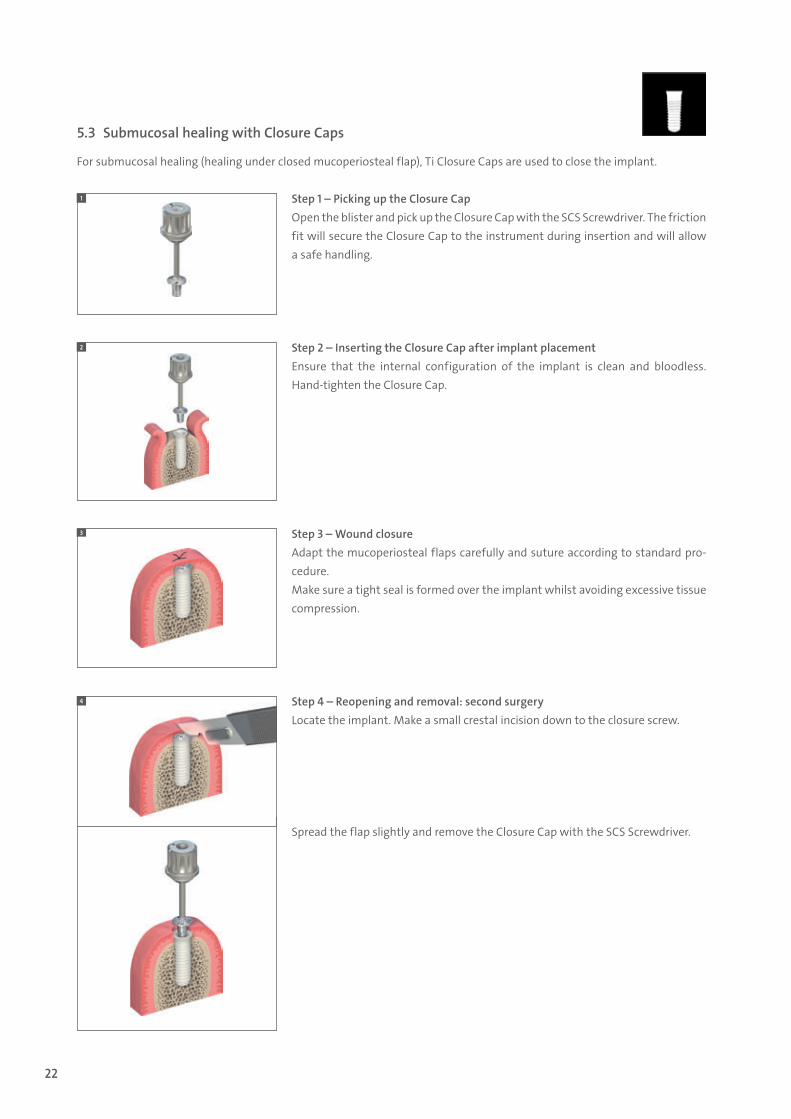
Step 1 – Picking up the Closure Cap Open the blister and pick up the Closure Cap with the SCS Screwdriver. The friction fit will secure the Closure Cap to the instrument during insertion and will allow a safe handling.
Step 2 – Inserting the Closure Cap after implant placementEnsure that the internal configuration of the implant is clean and bloodless. Hand-tighten the Closure Cap.
Step 3 – Wound closureAdapt the mucoperiosteal flaps carefully and suture according to standard pro-cedure. Make sure a tight seal is formed over the implant whilst avoiding excessive tissue compression.
Step 4 – Reopening and removal: second surgeryLocate the implant. Make a small crestal incision down to the closure screw.
Spread the flap slightly and remove the Closure Cap with the SCS Screwdriver.
5.3 Submucosal healing with Closure Caps
For submucosal healing (healing under closed mucoperiosteal flap), Ti Closure Caps are used to close the implant.
1
2
3
4
490.074_SbS_2pc_Pure.indd 22 23/05/2017 16:29
23
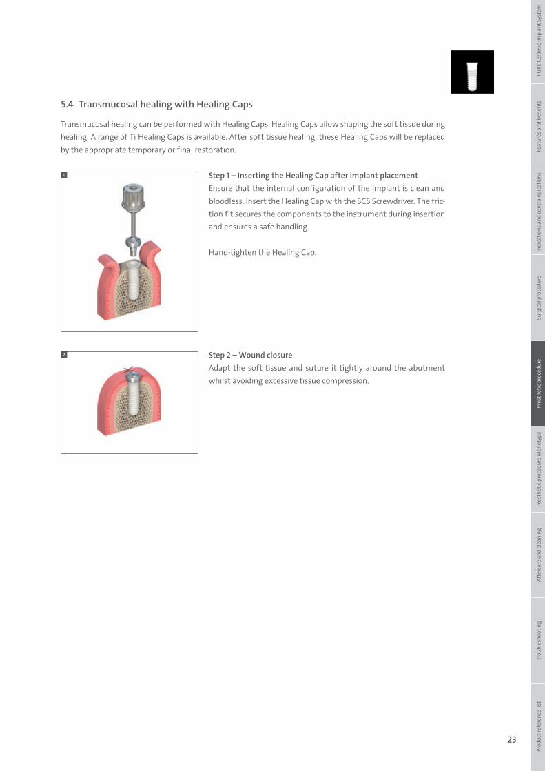
Step 1 – Inserting the Healing Cap after implant placementEnsure that the internal configuration of the implant is clean and bloodless. Insert the Healing Cap with the SCS Screwdriver. The fric-tion fit secures the components to the instrument during insertion and ensures a safe handling.
Hand-tighten the Healing Cap.
Step 2 – Wound closureAdapt the soft tissue and suture it tightly around the abutment whilst avoiding excessive tissue compression.
5.4 Transmucosal healing with Healing Caps
Transmucosal healing can be performed with Healing Caps. Healing Caps allow shaping the soft tissue during healing. A range of Ti Healing Caps is available. After soft tissue healing, these Healing Caps will be replaced by the appropriate temporary or final restoration.
1
2
Prod
uct r
efer
ence
list
Tr
oubl
esho
otin
gAf
terc
are
and
clea
ning
Pr
osth
etic
pro
cedu
re M
onot
ype
Pros
thet
ic p
roce
dure
Surg
ical
pro
cedu
reIn
dica
tions
and
cont
rain
dica
tions
Feat
ures
and
ben
efits
PURE
Cer
amic
Impl
ant S
yste
m
490.074_SbS_2pc_Pure.indd 23 23/05/2017 16:29
24
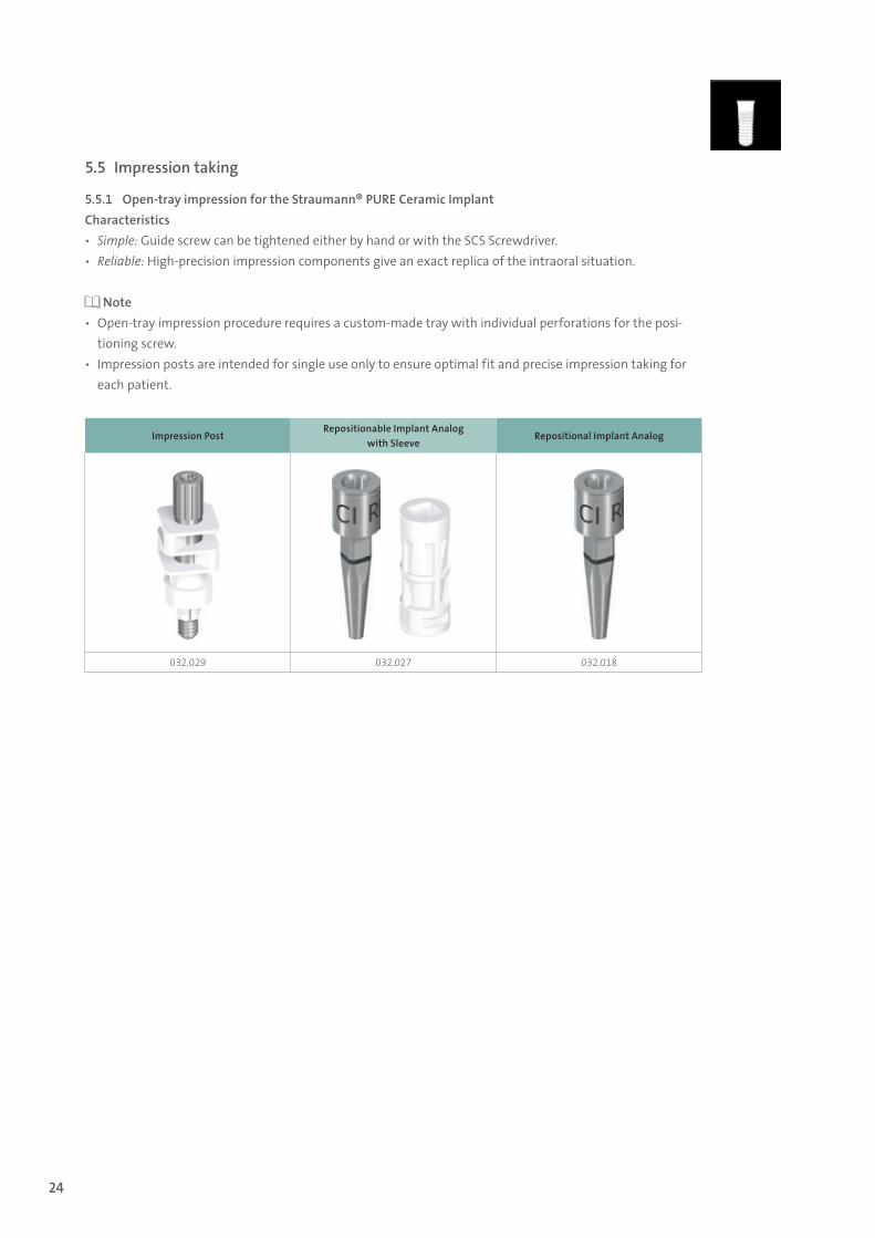
5.5 Impression taking
5.5.1 Open-tray impression for the Straumann® PURE Ceramic ImplantCharacteristics ѹ Simple: Guide screw can be tightened either by hand or with the SCS Screwdriver. ѹ Reliable: High-precision impression components give an exact replica of the intraoral situation.
Note ѹ Open-tray impression procedure requires a custom-made tray with individual perforations for the posi-
tioning screw. ѹ Impression posts are intended for single use only to ensure optimal fit and precise impression taking for
each patient.
Impression PostRepositionable Implant Analog
with SleeveRepositional Implant Analog
032.029 032.027 032.018
490.074_SbS_2pc_Pure.indd 24 23/05/2017 16:29
25
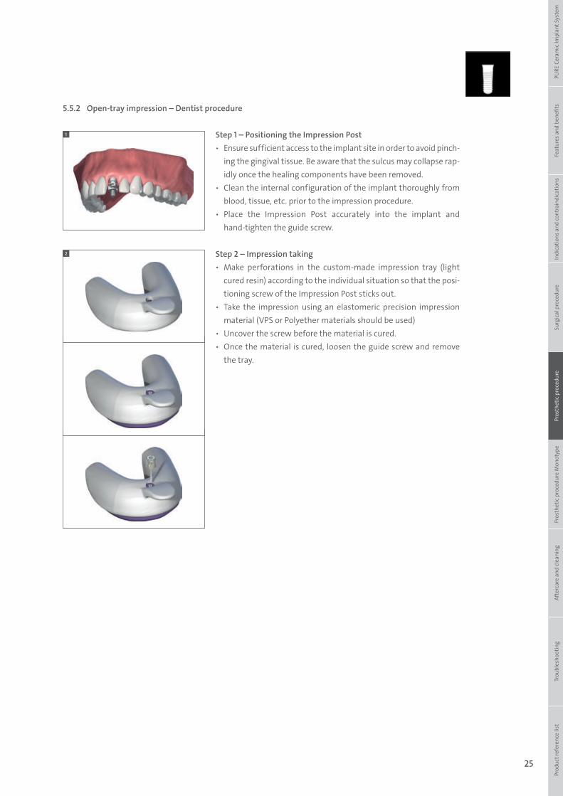
5.5.2 Open-tray impression – Dentist procedure
Step 1 – Positioning the Impression Post ѹ Ensure sufficient access to the implant site in order to avoid pinch-
ing the gingival tissue. Be aware that the sulcus may collapse rap-idly once the healing components have been removed.
ѹ Clean the internal configuration of the implant thoroughly from blood, tissue, etc. prior to the impression procedure.
ѹ Place the Impression Post accurately into the implant and hand-tighten the guide screw.
Step 2 – Impression taking ѹ Make perforations in the custom-made impression tray (light
cured resin) according to the individual situation so that the posi-tioning screw of the Impression Post sticks out.
ѹ Take the impression using an elastomeric precision impression material (VPS or Polyether materials should be used)
ѹ Uncover the screw before the material is cured. ѹ Once the material is cured, loosen the guide screw and remove
the tray.
1
2
Prod
uct r
efer
ence
list
Tr
oubl
esho
otin
gAf
terc
are
and
clea
ning
Pr
osth
etic
pro
cedu
re M
onot
ype
Pros
thet
ic p
roce
dure
Surg
ical
pro
cedu
reIn
dica
tions
and
cont
rain
dica
tions
Feat
ures
and
ben
efits
PURE
Cer
amic
Impl
ant S
yste
m
490.074_SbS_2pc_Pure.indd 25 23/05/2017 16:29
26
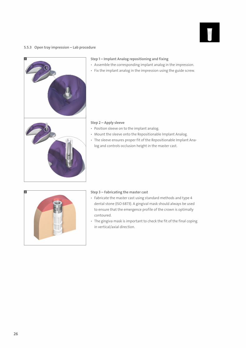
5.5.3 Open tray impression – Lab procedure
Step 1 – Implant Analog repositioning and fixing ѹ Assemble the corresponding implant analog in the impression. ѹ Fix the implant analog in the impression using the guide screw.
Step 2 – Apply sleeve ѹ Position sleeve on to the implant analog. ѹ Mount the sleeve onto the Repositionable Implant Analog. ѹ The sleeve ensures proper fit of the Repositionable Implant Ana-
log and controls occlusion height in the master cast.
Step 3 – Fabricating the master cast ѹ Fabricate the master cast using standard methods and type 4
dental stone (ISO 6873). A gingival mask should always be used to ensure that the emergence profile of the crown is optimally contoured.
ѹ The gingiva mask is important to check the fit of the final coping in vertical/axial direction.
1
2
490.074_SbS_2pc_Pure.indd 26 23/05/2017 16:29
27
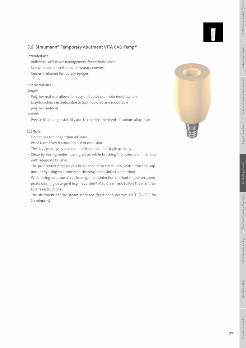
5.6 Straumann® Temporary Abutment VITA CAD-Temp®
Intended use ѹ Individual soft tissue management for esthetic cases. ѹ Screw- or cement-retained temporary crowns. ѹ Cement-retained temporary bridges.
CharacteristicsSimple ѹ Polymer material allows for easy and quick chair-side modification. ѹ Easy-to-achieve esthetics due to tooth-colored and modifiable
polymer material.Reliable ѹ Precise fit and high stability due to reinforcement with titanium alloy inlay.
Note ѹ Do not use for longer than 180 days. ѹ Place temporary restoration out of occlusion. ѹ The devices are provided non-sterile and are for single use only. ѹ Clean by rinsing under flowing water while brushing the outer and inner side
with adequate brushes. ѹ The pre-treated product can be cleaned either manually, with ultrasonic sup-
port, or by using an automated cleaning and disinfection method. ѹ When using an automated cleaning and disinfection method choose an appro-
priate cleaning detergent (e.g. neodisher® MediClean) and follow the manufac-turer’s instructions.
ѹ The abutment can be steam-sterilized (fractioned vaccum 121 °C (250 °F) for 20 minutes).
Prod
uct r
efer
ence
list
Tr
oubl
esho
otin
gAf
terc
are
and
clea
ning
Pr
osth
etic
pro
cedu
re M
onot
ype
Pros
thet
ic p
roce
dure
Surg
ical
pro
cedu
reIn
dica
tions
and
cont
rain
dica
tions
Feat
ures
and
ben
efits
PURE
Cer
amic
Impl
ant S
yste
m
490.074_SbS_2pc_Pure.indd 27 23/05/2017 16:29
28
5.6.1 Prosthetic procedure for Straumann® Temporary Abutment VITA CAD-Temp®
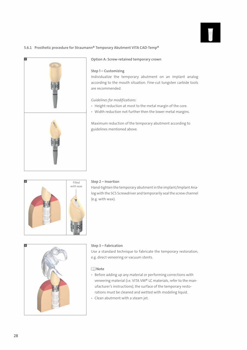
Option A: Screw-retained temporary crown
Step 1 – CustomizingIndividualize the temporary abutment on an implant analog according to the mouth situation. Fine-cut tungsten carbide tools are recommended.
Guidelines for modifications: ѹ Height reduction at most to the metal margin of the core. ѹ Width reduction not further then the lower metal margins.
Maximum reduction of the temporary abutment according to guidelines mentioned above.
Step 2 – InsertionHand-tighten the temporary abutment in the implant/Implant Ana-log with the SCS Screwdriver and temporarily seal the screw channel (e.g. with wax).
Step 3 – Fabrication Use a standard technique to fabricate the temporary restoration, e.g. direct veneering or vacuum stents.
Note ѹ Before adding up any material or performing corrections with
veneering material (i.e. VITA VM® LC materials, refer to the man-ufacturer’s instructions), the surface of the temporary resto-rations must be cleaned and wetted with modeling liquid.
ѹ Clean abutment with a steam jet.
1
3
2 Filled with wax
490.074_SbS_2pc_Pure.indd 28 23/05/2017 16:29
29
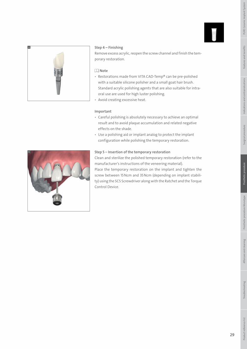
Step 4 – FinishingRemove excess acrylic, reopen the screw channel and finish the tem-porary restoration.
Note ѹ Restorations made from VITA CAD-Temp® can be pre-polished
with a suitable silicone polisher and a small goat hair brush. Standard acrylic polishing agents that are also suitable for intra-oral use are used for high luster polishing.
ѹ Avoid creating excessive heat.
Important ѹ Careful polishing is absolutely necessary to achieve an optimal
result and to avoid plaque accumulation and related negative effects on the shade.
ѹ Use a polishing aid or implant analog to protect the implant configuration while polishing the temporary restoration.
Step 5 – Insertion of the temporary restorationClean and sterilize the polished temporary restoration (refer to the manufacturer’s instructions of the veneering material).Place the temporary restoration on the implant and tighten the screw between 15 Ncm and 35 Ncm (depending on implant stabili-ty) using the SCS Screwdriver along with the Ratchet and the Torque Control Device.
4
5
Prod
uct r
efer
ence
list
Tr
oubl
esho
otin
gAf
terc
are
and
clea
ning
Pr
osth
etic
pro
cedu
re M
onot
ype
Pros
thet
ic p
roce
dure
Surg
ical
pro
cedu
reIn
dica
tions
and
cont
rain
dica
tions
Feat
ures
and
ben
efits
PURE
Cer
amic
Impl
ant S
yste
m
490.074_SbS_2pc_Pure.indd 29 23/05/2017 16:29
30
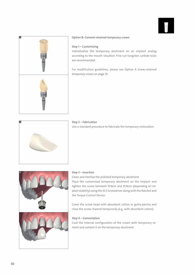
Option B: Cement-retained temporary crown
Step 1 – CustomizingIndividualize the temporary abutment on an implant analog according to the mouth situation. Fine-cut tungsten carbide tools are recommended
For modification guidelines, please see Option A Screw-retained temporary crown on page 35.
Step 2 – Fabrication Use a standard procedure to fabricate the temporary restoration.
Step 3 – InsertionClean and sterilize the polished temporary abutment.Place the customized temporary abutment on the implant and tighten the screw between 15 Ncm and 35 Ncm (depending on im-plant stability) using the SCS Screwdriver along with the Ratchet and the Torque Control Device.
Cover the screw head with absorbent cotton or gutta-percha and close the screw channel temporarily (e.g. with absorbent cotton).
Step 4 – CementationCoat the internal configuration of the crown with temporary ce-ment and cement it on the temporary abutment.
1
2
3
490.074_SbS_2pc_Pure.indd 30 23/05/2017 16:29
31
5.7 Creation and fixation of the final restoration
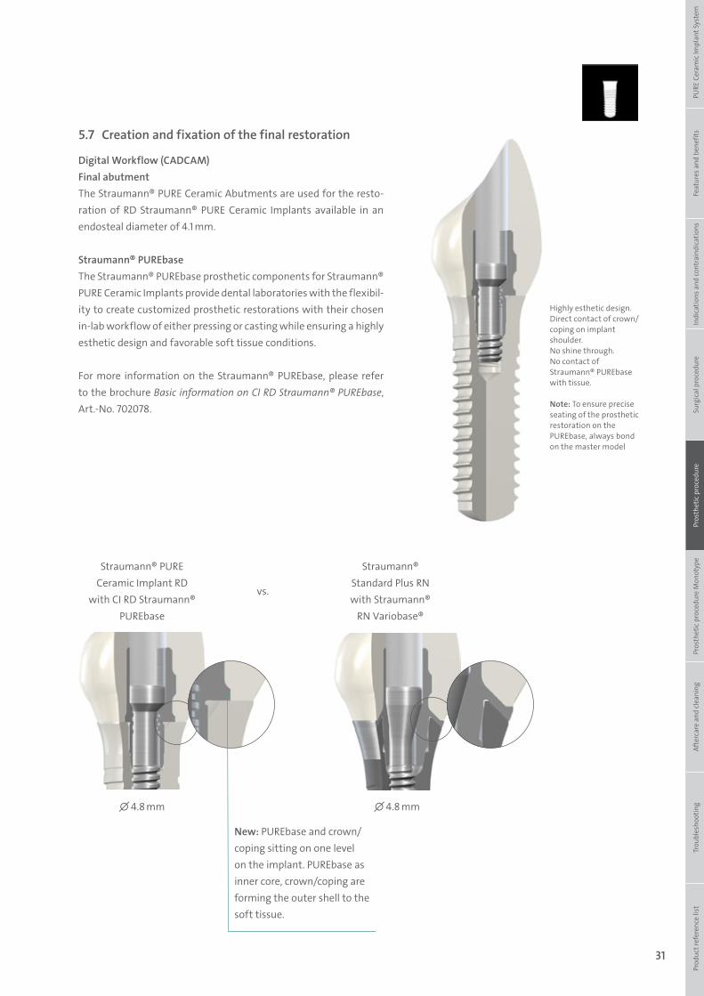
Digital Workflow (CADCAM)Final abutment The Straumann® PURE Ceramic Abutments are used for the resto-ration of RD Straumann® PURE Ceramic Implants available in an endosteal diameter of 4.1 mm.
Straumann® PUREbaseThe Straumann® PUREbase prosthetic components for Straumann® PURE Ceramic Implants provide dental laboratories with the flexibil-ity to create customized prosthetic restorations with their chosen in-lab workflow of either pressing or casting while ensuring a highly esthetic design and favorable soft tissue conditions.
For more information on the Straumann® PUREbase, please refer to the brochure Basic information on CI RD Straumann® PUREbase, Art.-No. 702078.
Highly esthetic design. Direct contact of crown/coping on implant shoulder. No shine through. No contact of Straumann® PUREbase with tissue.
Note: To ensure precise seating of the prosthetic restoration on the PUREbase, always bond on the master model
Straumann® PURE Ceramic Implant RD
with CI RD Straumann® PUREbase
∅ 4.8 mm ∅ 4.8 mm
vs.
Straumann® Standard Plus RN with Straumann®
RN Variobase®
Prod
uct r
efer
ence
list
Tr
oubl
esho
otin
gAf
terc
are
and
clea
ning
Pr
osth
etic
pro
cedu
re M
onot
ype
Pros
thet
ic p
roce
dure
Surg
ical
pro
cedu
reIn
dica
tions
and
cont
rain
dica
tions
Feat
ures
and
ben
efits
PURE
Cer
amic
Impl
ant S
yste
m
New: PUREbase and crown/coping sitting on one level on the implant. PUREbase as inner core, crown/coping are forming the outer shell to the soft tissue.
490.074_SbS_2pc_Pure.indd 31 23/05/2017 16:29
32
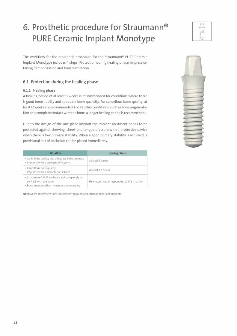
The workflow for the prosthetic procedure for the Straumann® PURE Ceramic Implant Monotype includes 4 steps: Protection during healing phase, impression taking, temporization and final restoration.
Note: Micro-movements disturb osseointegration and can lead to loss of implants.
6. Prosthetic procedure for Straumann® PURE Ceramic Implant Monotype
Situation Healing phase
▪ Good bone quality and adequate bone quantity. ▪ Implants with a diameter of 4.1 mm.
At least 6 weeks
▪ Cancellous bone quality. ▪ Implants with a diameter of 3.3 mm.
At least 12 weeks
▪ Straumann® ZLA® surface is not completely in contact with the bone.
▪ Bone augmentation measures are necessary.Healing phase corresponding to the situation
6.1 Protection during the healing phase
6.1.1 Healing phaseA healing period of at least 6 weeks is recommended for conditions where there is good bone quality and adequate bone quantity. For cancellous bone quality, at least 12 weeks are recommended. For all other conditions, such as bone augmenta-tion or incomplete contact with the bone, a longer healing period is recommended.
Due to the design of the one-piece implant the implant abutment needs to be protected against chewing, cheek and tongue pressure with a protective device when there is low primary stability. When a good primary stability is achieved, a provisional out of occlusion can be placed immediately.
490.074_SbS_2pc_Pure.indd 32 23/05/2017 16:29
33
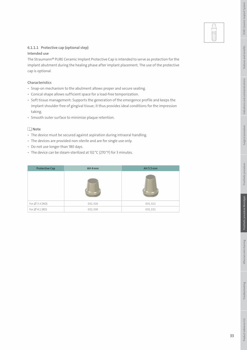
6.1.1.1 Protective cap (optional step)Intended useThe Straumann® PURE Ceramic Implant Protective Cap is intended to serve as protection for the implant abutment during the healing phase after implant placement. The use of the protective cap is optional.
Characteristics ѹ Snap-on mechanism to the abutment allows proper and secure seating. ѹ Conical shape allows sufficient space for a load-free temporization. ѹ Soft tissue management: Supports the generation of the emergence profile and keeps the
implant shoulder free of gingival tissue; it thus provides ideal conditions for the impression taking.
ѹ Smooth outer surface to minimize plaque retention.
Note ѹ The device must be secured against aspiration during intraoral handling. ѹ The devices are provided non-sterile and are for single use only. ѹ Do not use longer than 180 days. ѹ The device can be steam-sterilized at 132 °C (270 °F) for 3 minutes.
Protective Cap AH 4 mm AH 5.5 mm
For ∅ 3.3 (ND) 031.320 031.321
For ∅ 4.1 (RD) 031.330 031.331
Prod
uct r
efer
ence
list
Tr
oubl
esho
otin
gAf
terc
are
and
clea
ning
Pr
osth
etic
pro
cedu
re M
onot
ype
Pros
thet
ic p
roce
dure
Surg
ical
pro
cedu
reIn
dica
tions
and
cont
rain
dica
tions
Feat
ures
and
ben
efits
PURE
Cer
amic
Impl
ant S
yste
m
490.074_SbS_2pc_Pure.indd 33 23/05/2017 16:29
34
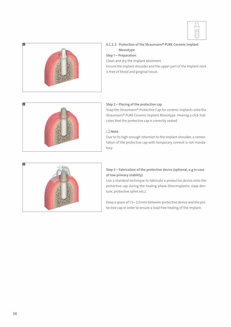
6.1.1.2 Protection of the Straumann® PURE Ceramic Implant Monotype
Step 1 – PreparationClean and dry the implant abutment. Ensure the implant shoulder and the upper part of the implant neck is free of blood and gingival tissue.
Step 2 – Placing of the protective capSnap the Straumann® Protective Cap for ceramic implants onto the Straumann® PURE Ceramic Implant Monotype. Hearing a click indi-cates that the protective cap is correctly seated.
NoteDue to its high-enough retention to the implant shoulder, a cemen-tation of the protective cap with temporary cement is not manda-tory.
Step 3 – Fabrication of the protective device (optional, e.g in case of low primary stability)Use a standard technique to fabricate a protective device onto the protective cap during the healing phase (thermoplastic clasp den-ture, protective splint etc.).
Keep a space of 1.5 – 2.0 mm between protective device and the pro-tective cap in order to ensure a load-free healing of the implant.
1
2
2
490.074_SbS_2pc_Pure.indd 34 23/05/2017 16:29

35
6.2 Impression taking
6.2.1 Closed-tray impression
CharacteristicsSimple ѹ Color-coded components corresponding to abutment height. ѹ No additional preparation (i.e. perforation) of tray required.
Reliable ѹ High precision impression components give an exact replica of the intraoral situation. ѹ Clear-cut tactile response from the prosthetic connection verifies proper seating of
components.
Note ѹ Impression posts are intended for single use only to ensure optimal fit and precise impres-
sion taking for each patient. ѹ Do not sterilize the impression posts. In order to prevent any damage (loss of elasticity or
embrittlement), they must be protected from strong light or heat irradiation. ѹ The parts can be disinfected as required using standard commercial disinfection agents for
plastic products (refer to the manufacturer’s instructions).
Impression Caps AH 4 mm AH 5.5 mm
For ∅ 3.3 (ND) 031.250 031.251
For ∅ 4.1 (RD) 031.260 031.261
Implant Analogs AH 4 mm AH 5.5 mm
For ∅ 3.3 (ND) 031.200 031.201
For ∅ 4.1 (RD) 031.210 031.211
Prod
uct r
efer
ence
list
Tr
oubl
esho
otin
gAf
terc
are
and
clea
ning
Pr
osth
etic
pro
cedu
re M
onot
ype
Pros
thet
ic p
roce
dure
Surg
ical
pro
cedu
reIn
dica
tions
and
cont
rain
dica
tions
Feat
ures
and
ben
efits
PURE
Cer
amic
Impl
ant S
yste
m
490.074_SbS_2pc_Pure.indd 35 23/05/2017 16:29
36
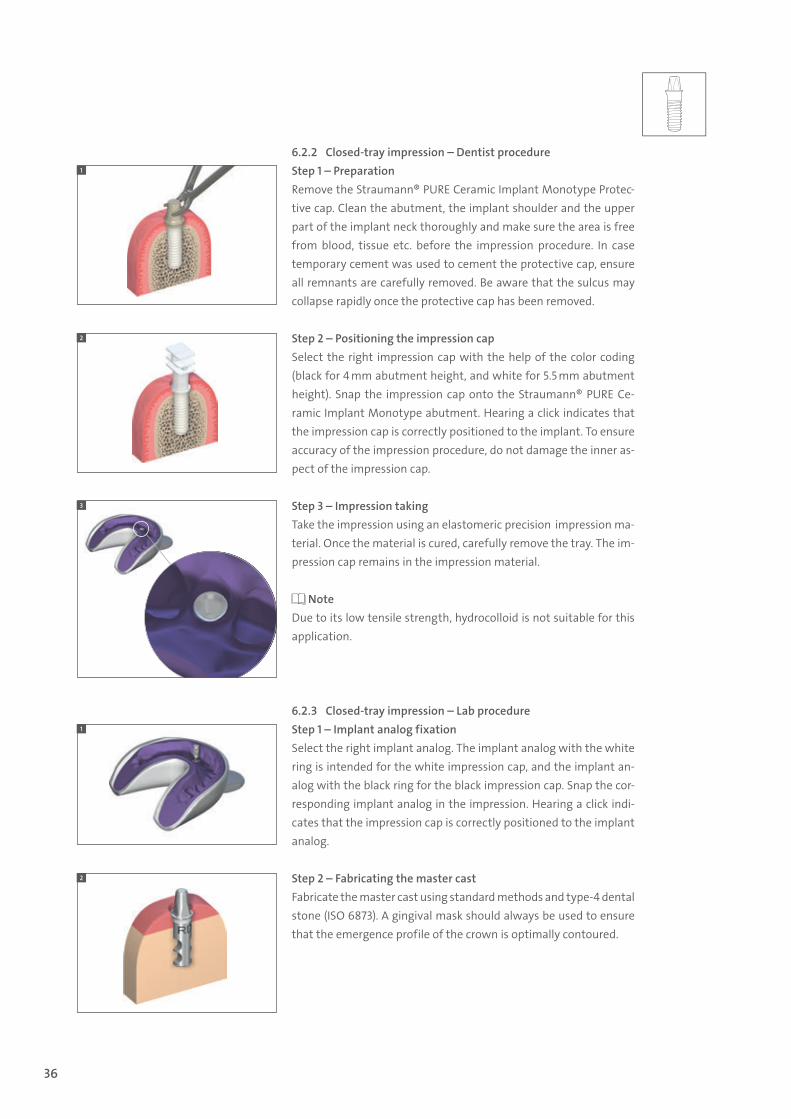
6.2.2 Closed-tray impression – Dentist procedureStep 1 – PreparationRemove the Straumann® PURE Ceramic Implant Monotype Protec-tive cap. Clean the abutment, the implant shoulder and the upper part of the implant neck thoroughly and make sure the area is free from blood, tissue etc. before the impression procedure. In case temporary cement was used to cement the protective cap, ensure all remnants are carefully removed. Be aware that the sulcus may collapse rapidly once the protective cap has been removed.
Step 2 – Positioning the impression cap Select the right impression cap with the help of the color coding (black for 4 mm abutment height, and white for 5.5 mm abutment height). Snap the impression cap onto the Straumann® PURE Ce-ramic Implant Monotype abutment. Hearing a click indicates that the impression cap is correctly positioned to the implant. To ensure accuracy of the impression procedure, do not damage the inner as-pect of the impression cap.
Step 3 – Impression takingTake the impression using an elastomeric precision impression ma-terial. Once the material is cured, carefully remove the tray. The im-pression cap remains in the impression material.
NoteDue to its low tensile strength, hydrocolloid is not suitable for this application.
6.2.3 Closed-tray impression – Lab procedureStep 1 – Implant analog fixationSelect the right implant analog. The implant analog with the white ring is intended for the white impression cap, and the implant an-alog with the black ring for the black impression cap. Snap the cor-responding implant analog in the impression. Hearing a click indi-cates that the impression cap is correctly positioned to the implant analog.
Step 2 – Fabricating the master castFabricate the master cast using standard methods and type-4 dental stone (ISO 6873). A gingival mask should always be used to ensure that the emergence profile of the crown is optimally contoured.
2
1
2
3
1
490.074_SbS_2pc_Pure.indd 36 23/05/2017 16:29
37
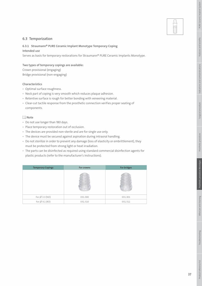
6.3 Temporization
6.3.1 Straumann® PURE Ceramic Implant Monotype Temporary CopingIntended useServes as basis for temporary restorations for Straumann® PURE Ceramic Implants Monotype.
Two types of temporary copings are available:Crown provisional (engaging) Bridge provisional (non-engaging)
Characteristics ѹ Optimal surface roughness. ѹ Neck part of coping is very smooth which reduces plaque adhesion. ѹ Retentive surface is rough for better bonding with veneering material. ѹ Clear-cut tactile response from the prosthetic connection verifies proper seating of
components.
Note ѹ Do not use longer than 180 days. ѹ Place temporary restoration out of occlusion. ѹ The devices are provided non-sterile and are for single use only. ѹ The device must be secured against aspiration during intraoral handling. ѹ Do not sterilize in order to prevent any damage (loss of elasticity or embrittlement), they
must be protected from strong light or heat irradiation. ѹ The parts can be disinfected as required using standard commercial disinfection agents for
plastic products (refer to the manufacturer’s instructions).
Temporary Copings For crowns For bridges
For ∅ 3.3 (ND) 031.300 031.301
For ∅ 4.1 (RD) 031.310 031.311Pr
oduc
t ref
eren
ce li
st
Trou
bles
hoot
ing
Afte
rcar
e an
d cl
eani
ng
Pros
thet
ic p
roce
dure
Mon
otyp
ePr
osth
etic
pro
cedu
reSu
rgic
al p
roce
dure
Indi
catio
ns a
nd co
ntra
indi
catio
nsFe
atur
es a
nd b
enef
itsPU
RE C
eram
ic Im
plan
t Sys
tem
490.074_SbS_2pc_Pure.indd 37 23/05/2017 16:29
38
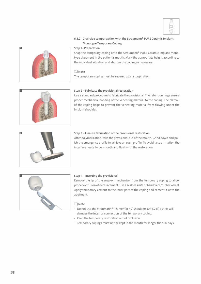
6.3.2 Chairside temporization with the Straumann® PURE Ceramic Implant Monotype Temporary Coping
Step 1– PreparationSnap the temporary coping onto the Straumann® PURE Ceramic Implant Mono-type abutment in the patient’s mouth. Mark the appropriate height according to the individual situation and shorten the coping as necessary.
NoteThe temporary coping must be secured against aspiration.
Step 2 – Fabricate the provisional restorationUse a standard procedure to fabricate the provisional. The retention rings ensure proper mechanical bonding of the veneering material to the coping. The plateau of the coping helps to prevent the veneering material from flowing under the implant shoulder.
Step 3 – Finalize fabrication of the provisional restorationAfter polymerization, take the provisional out of the mouth. Grind down and pol-ish the emergence profile to achieve an even profile. To avoid tissue irritation the interface needs to be smooth and flush with the restoration
Step 4 – Inserting the provisionalRemove the lip of the snap-on mechanism from the temporary coping to allow proper extrusion of excess cement. Use a scalpel, knife or handpiece/rubber wheel. Apply temporary cement to the inner part of the coping and cement it onto the abutment.
Note ѹ Do not use the Straumann® Reamer for 45° shoulders (046.243) as this will
damage the internal connection of the temporary coping. ѹ Keep the temporary restoration out of occlusion. ѹ Temporary copings must not be kept in the mouth for longer than 30 days.
1
2
2
2
490.074_SbS_2pc_Pure.indd 38 23/05/2017 16:29
39
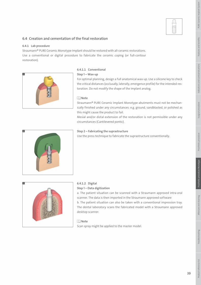
6.4 Creation and cementation of the final restoration
6.4.1 Lab procedureStraumann® PURE Ceramic Monotype Implant should be restored with all-ceramic restorations. Use a conventional or digital procedure to fabricate the ceramic coping (or full-contour restoration).
6.4.1.1 ConventionalStep 1 – Wax-upFor optimal planning, design a full anatomical wax-up. Use a silicone key to check the critical distances (occlusally, laterally, emergence profile) for the intended res-toration. Do not modify the shape of the implant analog.
NoteStraumann® PURE Ceramic Implant Monotype abutments must not be mechan-ically finished under any circumstances: e.g. ground, sandblasted, or polished as this might cause the product to fail. Mesial and/or distal extension of the restoration is not permissible under any circumstances (Cantilevered pontic).
Step 2 – Fabricating the suprastructureUse the press technique to fabricate the suprastructure conventionally.
6.4.1.2 DigitalStep 1 – Data digitizationa. The patient situation can be scanned with a Straumann approved intra-oral scanner. The data is then imported in the Straumann approved softwareb. The patient situation can also be taken with a conventional impression tray. The dental laboratory scans the fabricated model with a Straumann approved desktop scanner.
NoteScan spray might be applied to the master model.
1
2
Prod
uct r
efer
ence
list
Tr
oubl
esho
otin
gAf
terc
are
and
clea
ning
Pr
osth
etic
pro
cedu
re M
onot
ype
Pros
thet
ic p
roce
dure
Surg
ical
pro
cedu
reIn
dica
tions
and
cont
rain
dica
tions
Feat
ures
and
ben
efits
PURE
Cer
amic
Impl
ant S
yste
m
1
490.074_SbS_2pc_Pure.indd 39 23/05/2017 16:29
40
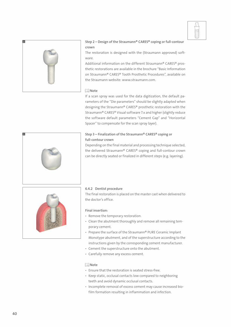
Step 2 – Design of the Straumann® CARES® coping or full-contour crownThe restoration is designed with the (Straumann approved) soft-ware.Additional information on the different Straumann® CARES® pros-thetic restorations are available in the brochure “Basic Information on Straumann® CARES® Tooth Prosthetic Procedures”, available on the Straumann website: www.straumann.com.
NoteIf a scan spray was used for the data digitization, the default pa-rameters of the “Die parameters” should be slightly adapted when designing the Straumann® CARES® prosthetic restoration with the Straumann® CARES® Visual software 7.x and higher (slightly reduce the software default parameters “Cement Gap” and “Horizontal Spacer” to compensate for the scan spray layer).
Step 3 – Finalization of the Straumann® CARES® coping or full-contour crownDepending on the final material and processing technique selected, the delivered Straumann® CARES® coping and full-contour crown can be directly seated or finalized in different steps (e.g. layering).
6.4.2 Dentist procedureThe final restoration is placed on the master cast when delivered to the doctor’s office.
Final insertion: ѹ Remove the temporary restoration. ѹ Clean the abutment thoroughly and remove all remaining tem-
porary cement. ѹ Prepare the surface of the Straumann® PURE Ceramic Implant
Monotype abutment, and of the superstructure according to the instructions given by the corresponding cement manufacturer.
ѹ Cement the superstructure onto the abutment. ѹ Carefully remove any excess cement.
Note ѹ Ensure that the restoration is seated stress-free. ѹ Keep static, occlusal contacts low compared to neighboring
teeth and avoid dynamic occlusal contacts. ѹ Incomplete removal of excess cement may cause increased bio-
film formation resulting in inflammation and infection.
2
3
490.074_SbS_2pc_Pure.indd 40 23/05/2017 16:29
41
7. Aftercare and cleaning of Straumann® PURE Ceramic Implant
8. Troubleshooting
Regular prosthetic aftercare of the Straumann® PURE Ce-ramic Implants is necessary, as in all implant systems. Since individual factors such as oral hygiene of the patient, coop-eration, etc. are of great importance in determining regular prosthetic aftercare, the aftercare should be adapted to each patient individually.
Zirconia has very low affinity to plaque. However, regular and adequate prophylaxis is recommended. For cleaning Straumann® PURE Ceramic Implants, use non-metallic hand scalers and curettes only.
Rinsing solutions of chlorhexidine and/or alcohol basis can be used temporarily without reservation. These solutions are not recommended for continuous use due to possible discoloration of the tooth hard substance as well as of ce-ment gaps.
Do not use any ultrasound-operated, metallic cleaning aids for cleaning Straumann® PURE Ceramic Implants. Avoid application of ultrasound through metallic transmitters onto Straumann® PURE Ceramic Implants. The surface can be damaged permanently by incorrect use and applica-tion of ultrasound. When metallic cleaning aids are used (ultrsound- operated scalers or hand curettes or scalers) metallic abrasion might occur on the surface of the implant.
Do not use any abrasive prophylactic pastes for cleaning Straumann® PURE Ceramic Implants. Powder/water jet cleaners are not suitable for cleaning Straumann® PURE Ceramic Implants.
8.1 Implant removal
Non-osseointegrated implant (spinner)The 48h Explantation Device for Straumann® PURE Ceramic Implant System can be used to help remove a non-osseointe-grated implant.
Note Osseointegrated implant: Bone preservation is considered to be a core competence required by the clinician in the case of implant removal. The clinician should use a technique suit-able to the implant and patient situation. Please refer to the brochure Guidance for Implant Removal 152.806/en.
8.2 Fracture of the abutment (Straumann® PURE Ceramic Implant Monotype)
If part of the PURE Ceramic Implant Monotype abutment fractures, the clinician needs to determine if another resto-ration can be placed or the implant must be explanted. When determining if there is enough minimum support and reten-tive area, use the same parameters that apply for a natural tooth stump.
Chipping or cracking of crownIn the event of a chipped or cracked crown, where the crown needs to be removed, care should be taken to avoid damag-ing the implant shoulder or abutment.
Prod
uct r
efer
ence
list
Tr
oubl
esho
otin
gAf
terc
are
and
clea
ning
Pr
osth
etic
pro
cedu
re M
onot
ype
Pros
thet
ic p
roce
dure
Surg
ical
pro
cedu
reIn
dica
tions
and
cont
rain
dica
tions
Feat
ures
and
ben
efits
PURE
Cer
amic
Impl
ant S
yste
m
490.074_SbS_2pc_Pure.indd 41 23/05/2017 16:29
42
9. Product reference list
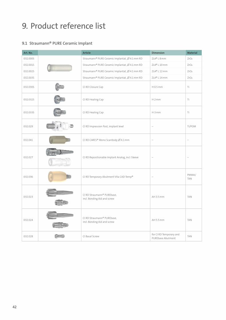
9.1 Straumann® PURE Ceramic Implant
Art. No. Article Dimension Material
032.000S Straumann® PURE Ceramic Implantat, ∅ 4.1 mm RD ZLA® L 8 mm ZrO2
032.001S Straumann® PURE Ceramic Implantat, ∅ 4.1 mm RD ZLA® L 10 mm ZrO2
032.002S Straumann® PURE Ceramic Implantat, ∅ 4.1 mm RD ZLA® L 12 mm ZrO2
032.003S Straumann® PURE Ceramic Implantat, ∅ 4.1 mm RD ZLA® L 14 mm ZrO2
032.030S CI RD Closure Cap H 0.5 mm Ti
032.032S CI RD Healing Cap H 2 mm Ti
032.033S CI RD Healing Cap H 3 mm Ti
032.029 CI RD Impression Post, implant level – Ti/POM
032.041 CI RD CARES® Mono Scanbody ∅ 4.1 mm – –
032.027 CI RD Repositionable Implant Analog, incl. Sleeve – –
032.036 CI RD Temporary Abutment Vita CAD-Temp® –PMMA/TAN
032.023CI RD Straumann® PUREbase, incl. Bonding Aid and screw
AH 3.5 mm TAN
032.024CI RD Straumann® PUREbase, incl. Bonding Aid and screw
AH 5.5 mm TAN
032.028 CI Basal Screwfor CI RD Temporary and PUREbase Abutment
TAN
490.074_SbS_2pc_Pure.indd 42 23/05/2017 16:29
43
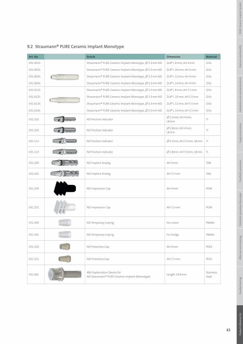
9.2 Straumann® PURE Ceramic Implant Monotype
Art. No. Article Dimension Material
031.001S Straumann® PURE Ceramic Implant Monotype, ∅ 3.3 mm ND ZLA® L 8 mm, AH 4 mm ZrO2
031.002S Straumann® PURE Ceramic Implant Monotype, ∅ 3.3 mm ND ZLA® L 10 mm, AH 4 mm ZrO2
031.003S Straumann® PURE Ceramic Implant Monotype, ∅ 3.3 mm ND ZLA® L 12 mm, AH 4 mm ZrO2
031.004S Straumann® PURE Ceramic Implant Monotype, ∅ 3.3 mm ND ZLA® L 14 mm, AH 4 mm ZrO2
031.011S Straumann® PURE Ceramic Implant Monotype, ∅ 3.3 mm ND ZLA® L 8 mm, AH 5.5 mm ZrO2
031.012S Straumann® PURE Ceramic Implant Monotype, ∅ 3.3 mm ND ZLA® L 10 mm, AH 5.5 mm ZrO2
031.013S Straumann® PURE Ceramic Implant Monotype, ∅ 3.3 mm ND ZLA® L 12 mm, AH 5.5 mm ZrO2
031.014S Straumann® PURE Ceramic Implant Monotype, ∅ 3.3 mm ND ZLA® L 14 mm, AH 5.5 mm ZrO2
031.102 ND Position Indicator∅ 2.2mm, AH 4 mm, L8 mm
Ti
031.103 ND Position Indicator∅ 2.8mm, AH 4 mm, L8 mm
Ti
031.112 ND Position Indicator ∅ 2.2mm, AH 5.5mm, L8 mm Ti
031.113 ND Position Indicator ∅ 2.8mm, AH 5.5mm, L8 mm Ti
031.200 ND Implant Analog AH 4 mm TAN
031.201 ND Implant Analog AH 5.5 mm TAN
031.250 ND Impression Cap AH 4 mm POM
031.251 ND Impression Cap AH 5.5 mm POM
031.300 ND Temporary Coping For crown PMMA
031.301 ND Temporary Coping For bridge PMMA
031.320 ND Protective Cap AH 4 mm PEEK
031.321 ND Protective Cap AH 5.5 mm PEEK
031.08148h Explantation Device for ND Straumann® PURE Ceramic Implant (Monotype)
Length 19.8 mmStainless steel
Prod
uct r
efer
ence
list
Tr
oubl
esho
otin
gAf
terc
are
and
clea
ning
Pr
osth
etic
pro
cedu
re M
onot
ype
Pros
thet
ic p
roce
dure
Surg
ical
pro
cedu
reIn
dica
tions
and
cont
rain
dica
tions
Feat
ures
and
ben
efits
PURE
Cer
amic
Impl
ant S
yste
m
490.074_SbS_2pc_Pure.indd 43 23/05/2017 16:29
44
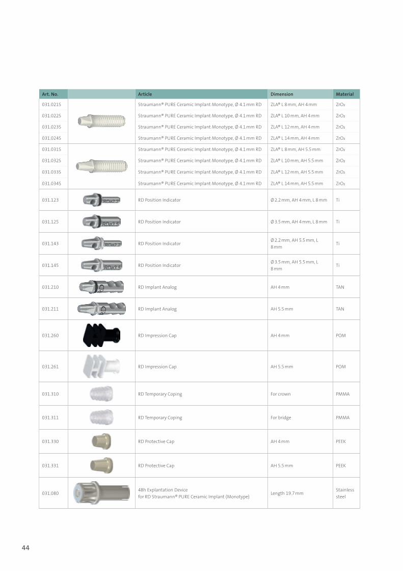
Art. No. Article Dimension Material
031.021S Straumann® PURE Ceramic Implant Monotype, Ø 4.1 mm RD ZLA® L 8 mm, AH 4 mm ZrO2
031.022S Straumann® PURE Ceramic Implant Monotype, Ø 4.1 mm RD ZLA® L 10 mm, AH 4 mm ZrO2
031.023S Straumann® PURE Ceramic Implant Monotype, Ø 4.1 mm RD ZLA® L 12 mm, AH 4 mm ZrO2
031.024S Straumann® PURE Ceramic Implant Monotype, Ø 4.1 mm RD ZLA® L 14 mm, AH 4 mm ZrO2
031.031S Straumann® PURE Ceramic Implant Monotype, Ø 4.1 mm RD ZLA® L 8 mm, AH 5.5 mm ZrO2
031.032S Straumann® PURE Ceramic Implant Monotype, Ø 4.1 mm RD ZLA® L 10 mm, AH 5.5 mm ZrO2
031.033S Straumann® PURE Ceramic Implant Monotype, Ø 4.1 mm RD ZLA® L 12 mm, AH 5.5 mm ZrO2
031.034S Straumann® PURE Ceramic Implant Monotype, Ø 4.1 mm RD ZLA® L 14 mm, AH 5.5 mm ZrO2
031.123 RD Position Indicator Ø 2.2 mm, AH 4 mm, L 8 mm Ti
031.125 RD Position Indicator Ø 3.5 mm, AH 4 mm, L 8 mm Ti
031.143 RD Position IndicatorØ 2.2 mm, AH 5.5 mm, L 8 mm
Ti
031.145 RD Position IndicatorØ 3.5 mm, AH 5.5 mm, L 8 mm
Ti
031.210 RD Implant Analog AH 4 mm TAN
031.211 RD Implant Analog AH 5.5 mm TAN
031.260 RD Impression Cap AH 4 mm POM
031.261 RD Impression Cap AH 5.5 mm POM
031.310 RD Temporary Coping For crown PMMA
031.311 RD Temporary Coping For bridge PMMA
031.330 RD Protective Cap AH 4 mm PEEK
031.331 RD Protective Cap AH 5.5 mm PEEK
031.08048h Explantation Device for RD Straumann® PURE Ceramic Implant (Monotype)
Length 19.7 mmStainless steel
490.074_SbS_2pc_Pure.indd 44 23/05/2017 16:29

45
Prod
uct r
efer
ence
list
Tr
oubl
esho
otin
gAf
terc
are
and
clea
ning
Pr
osth
etic
pro
cedu
re M
onot
ype
Pros
thet
ic p
roce
dure
Surg
ical
pro
cedu
reIn
dica
tions
and
cont
rain
dica
tions
Feat
ures
and
ben
efits
PURE
Cer
amic
Impl
ant S
yste
m
490.074_SbS_2pc_Pure.indd 45 23/05/2017 16:29

International HeadquartersInstitut Straumann AGPeter Merian-Weg 12CH-4002 Basel, SwitzerlandPhone +41 (0)61 965 11 11Fax +41 (0)61 965 11 01www.straumann.com
© Institut Straumann AG, 2017. All rights reserved.Straumann® and/or other trademarks and logos from Straumann® mentioned herein are the trademarks or registered trademarks of Straumann Holding AG and/or its affiliates. All rights reserved.
49
0.07
4/en
/B/0
0 04
/17
490.074_SbS_2pc_Pure.indd 46 23/05/2017 16:29