Pure bending - Judha Purbolaksono
23
Pure Bending
Transcript of Pure bending - Judha Purbolaksono
Pure Bending
Pure BendingPure BendingPure BendingPure Bending
4 - 2
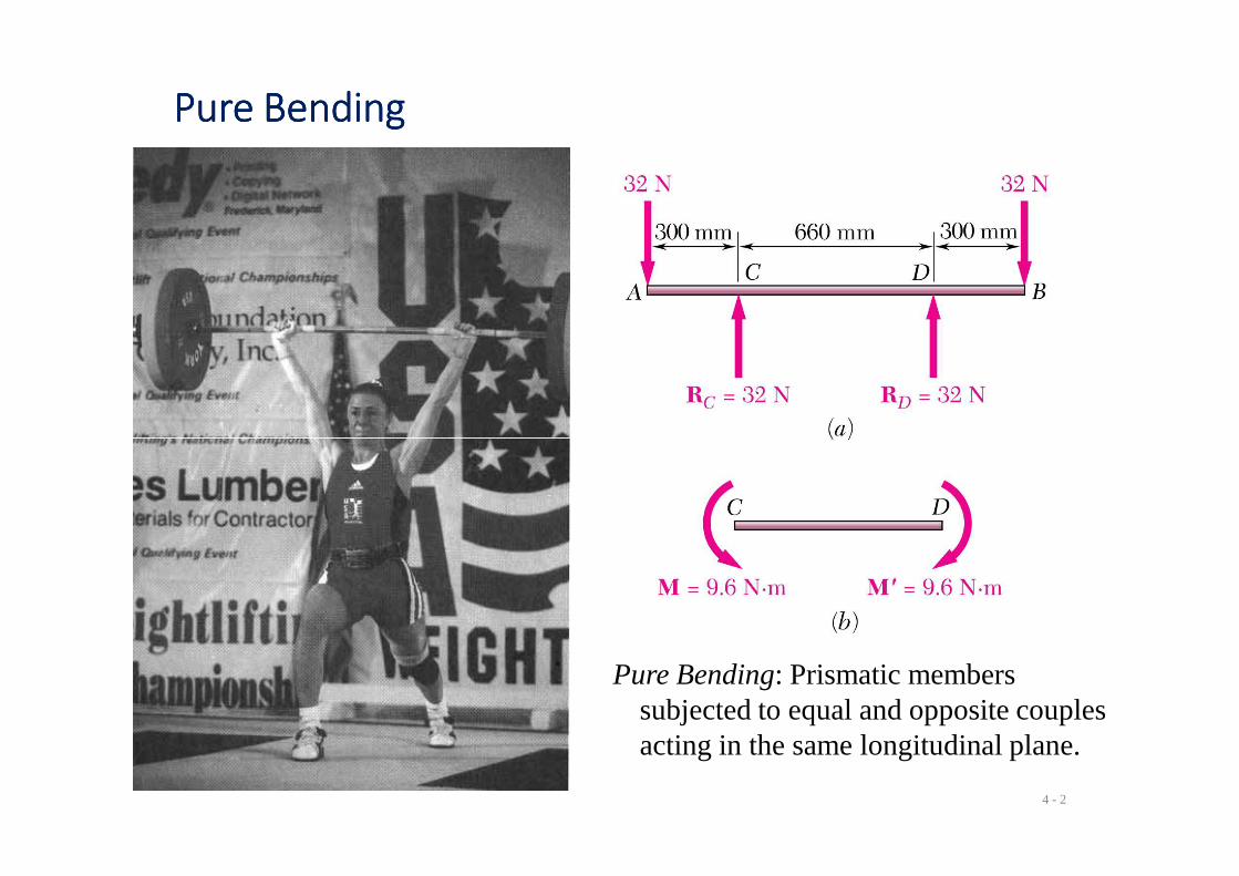
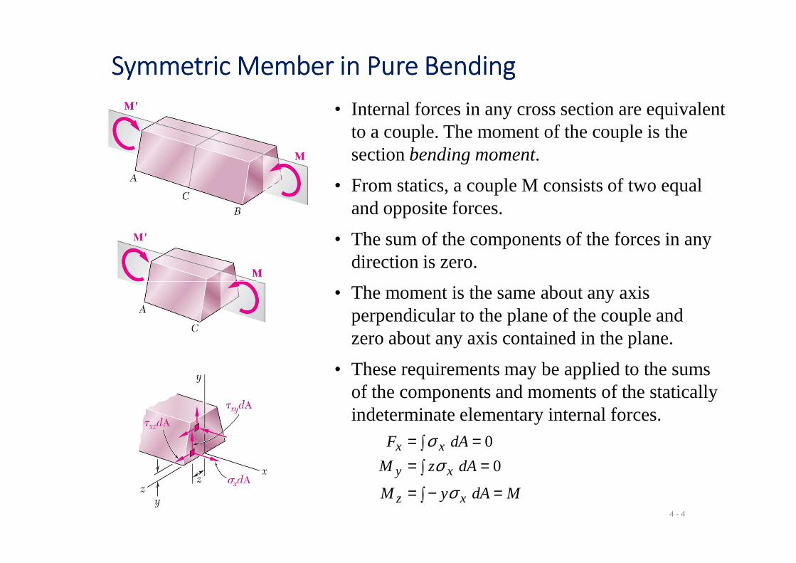
Pure Bending: Prismatic members subjected to equal and opposite couples acting in the same longitudinal plane.
Other Loading TypesOther Loading TypesOther Loading TypesOther Loading Types
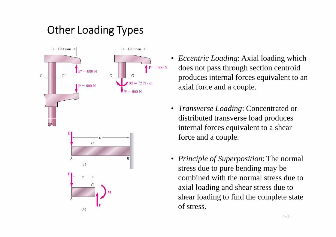
• Eccentric Loading: Axial loading which does not pass through section centroid produces internal forces equivalent to an axial force and a couple.
• Transverse Loading: Concentrated or distributed transverse load produces
4 - 3
• Principle of Superposition: The normal stress due to pure bending may be combined with the normal stress due to axial loading and shear stress due to shear loading to find the complete state of stress.
distributed transverse load produces internal forces equivalent to a shear force and a couple.
Symmetric Member in Pure BendingSymmetric Member in Pure BendingSymmetric Member in Pure BendingSymmetric Member in Pure Bending
• Internal forces in any cross section are equivalent to a couple. The moment of the couple is the section bending moment.
• From statics, a couple M consists of two equal and opposite forces.
• The sum of the components of the forces in any direction is zero.
4 - 4
∫ =−=∫ ==∫ ==
MdAyM
dAzM
dAF
xz
xy
xx
σσ
σ0
0
• These requirements may be applied to the sums of the components and moments of the statically indeterminate elementary internal forces.
• The moment is the same about any axis perpendicular to the plane of the couple and zero about any axis contained in the plane.
Bending DeformationsBending DeformationsBending DeformationsBending Deformations
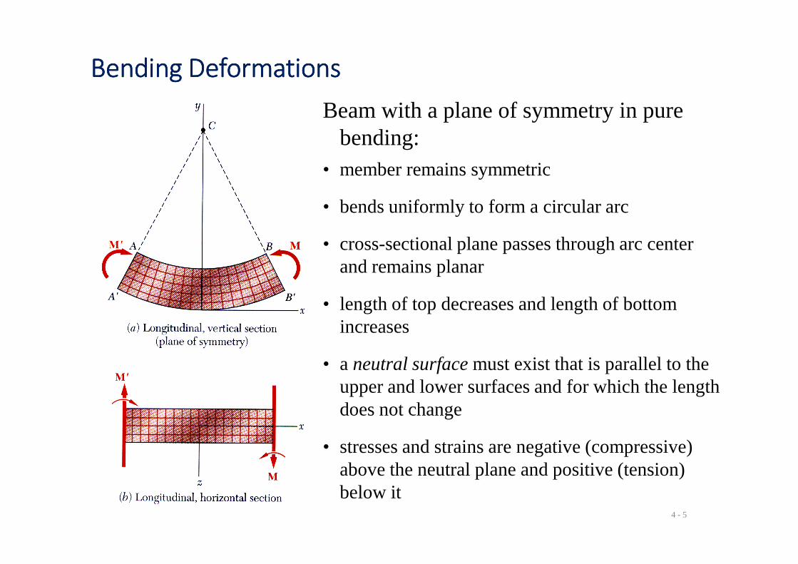
Beam with a plane of symmetry in pure bending:
• member remains symmetric
• bends uniformly to form a circular arc
• cross-sectional plane passes through arc centerand remains planar
4 - 5
• length of top decreases and length of bottom increases
• a neutral surface must exist that is parallel to the upper and lower surfaces and for which the length does not change
• stresses and strains are negative (compressive) above the neutral plane and positive (tension) below it
Strain Due to BendingStrain Due to BendingStrain Due to BendingStrain Due to Bending
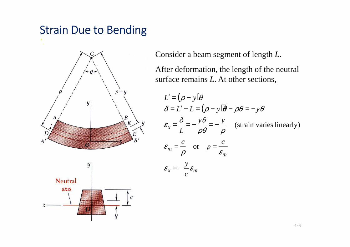
Consider a beam segment of length L.
After deformation, the length of the neutral surface remains L. At other sections,
( )( )
yy
yyLL
yL
θδε
θρθθρδθρ
−=−==
−=−−=−′=−=′
linearly) ries(strain va
4 - 6
mx
mm
x
c
y
cρ
c
yy
L
εε
ερε
ρρθθδε
−=
==
−=−==
or
linearly) ries(strain va
Stress Due to BendingStress Due to BendingStress Due to BendingStress Due to Bending
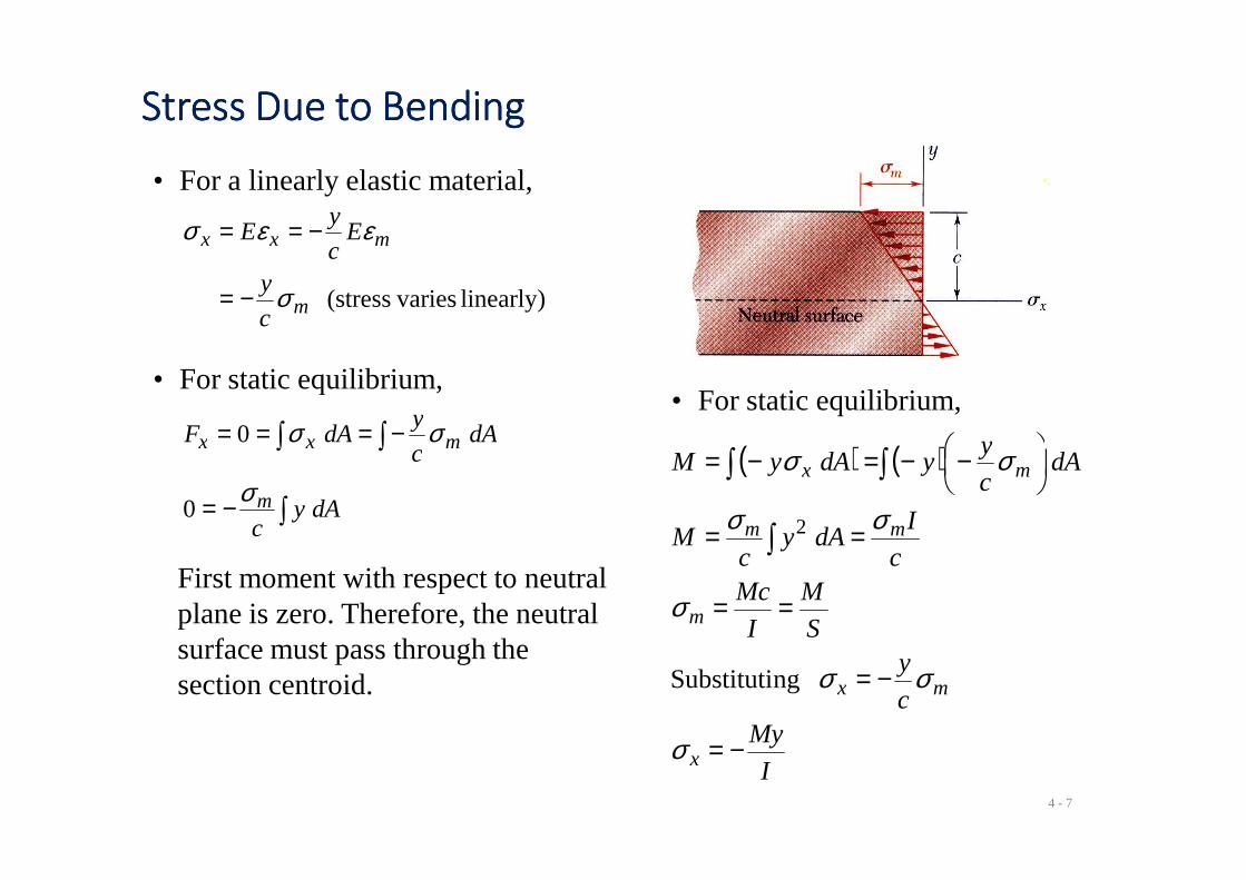
• For a linearly elastic material,
linearly) varies(stressm
mxx
c
y
Ec
yE
σ
εεσ
−=
−==
• For static equilibrium,
∫∫ −=== dAc
ydAF mxx σσ0
• For static equilibrium,
( ) ( ) y
4 - 7
∫
∫∫
−=
−===
dAyc
dAc
dAF
m
mxx
σ
σσ
0
0
First moment with respect to neutral plane is zero. Therefore, the neutral surface must pass through the section centroid.
( ) ( )
I
Myc
yS
M
I
Mcc
IdAy
cM
dAc
yydAyM
x
mx
m
mm
mx
−=
−=
==
==
−−=−=
∫
∫∫
σ
σσ
σ
σσ
σσ
ngSubstituti
2
Beam Section PropertiesBeam Section PropertiesBeam Section PropertiesBeam Section Properties
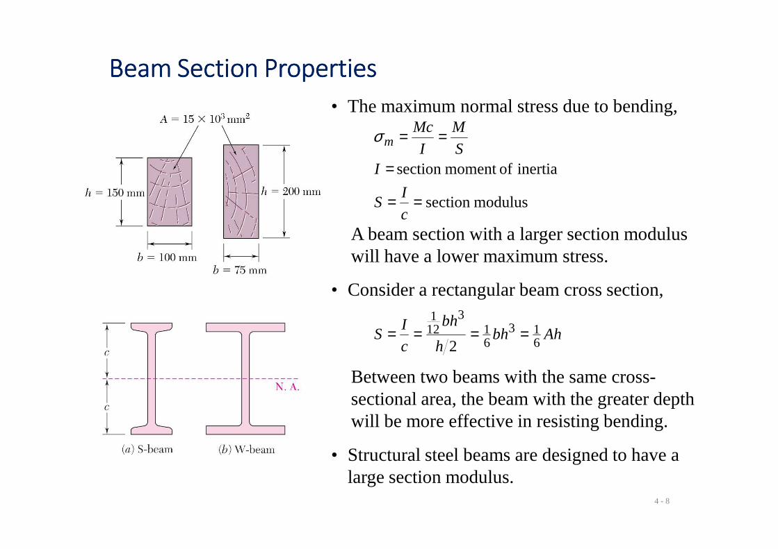
• The maximum normal stress due to bending,
modulussection
inertia ofmoment section
==
=
==
c
IS
IS
M
I
Mcmσ
A beam section with a larger section modulus will have a lower maximum stress.
4 - 8
• Consider a rectangular beam cross section,
Ahbhh
bh
c
IS
613
61
3121
2====
Between two beams with the same cross-sectional area, the beam with the greater depth will be more effective in resisting bending.
• Structural steel beams are designed to have a large section modulus.
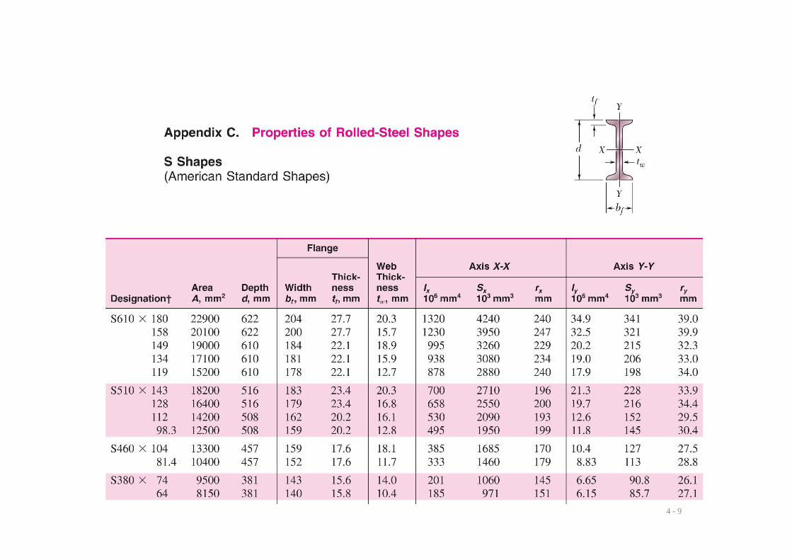
Properties of American Standard Shapes
4 - 9
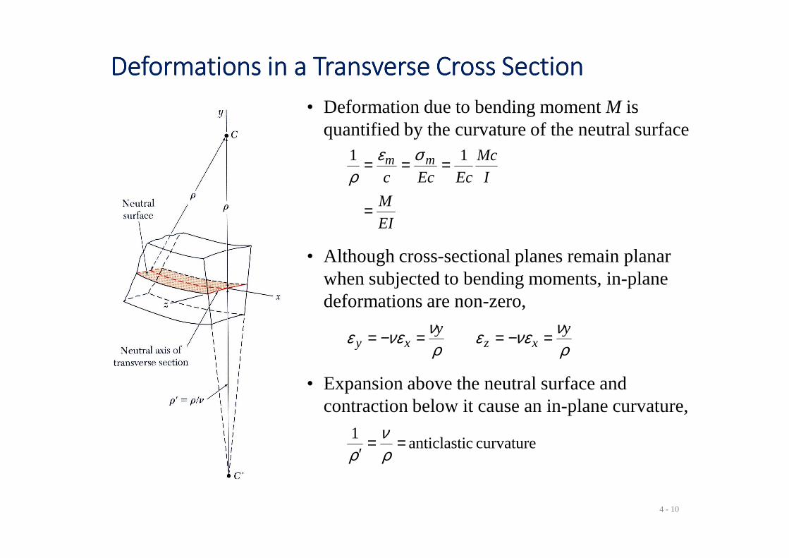
Deformations in a Transverse Cross SectionDeformations in a Transverse Cross SectionDeformations in a Transverse Cross SectionDeformations in a Transverse Cross Section
• Deformation due to bending moment M is quantified by the curvature of the neutral surface
EI
M
I
Mc
EcEccmm
=
=== 11 σερ
• Although cross-sectional planes remain planar when subjected to bending moments, in-plane
4 - 10
when subjected to bending moments, in-plane deformations are non-zero,
ρννεε
ρννεε yy
xzxy =−==−=
• Expansion above the neutral surface and contraction below it cause an in-plane curvature,
curvature canticlasti 1 ==′ ρ
νρ
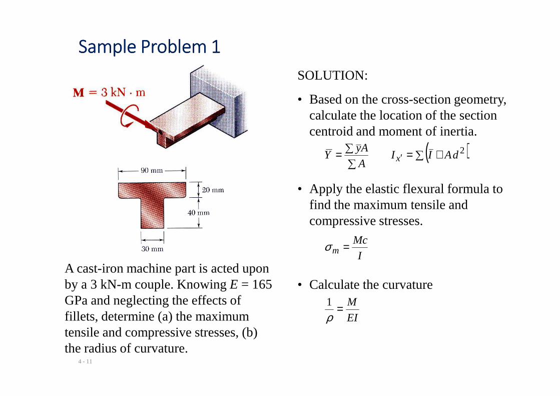
Sample Problem 1Sample Problem 1Sample Problem 1Sample Problem 1
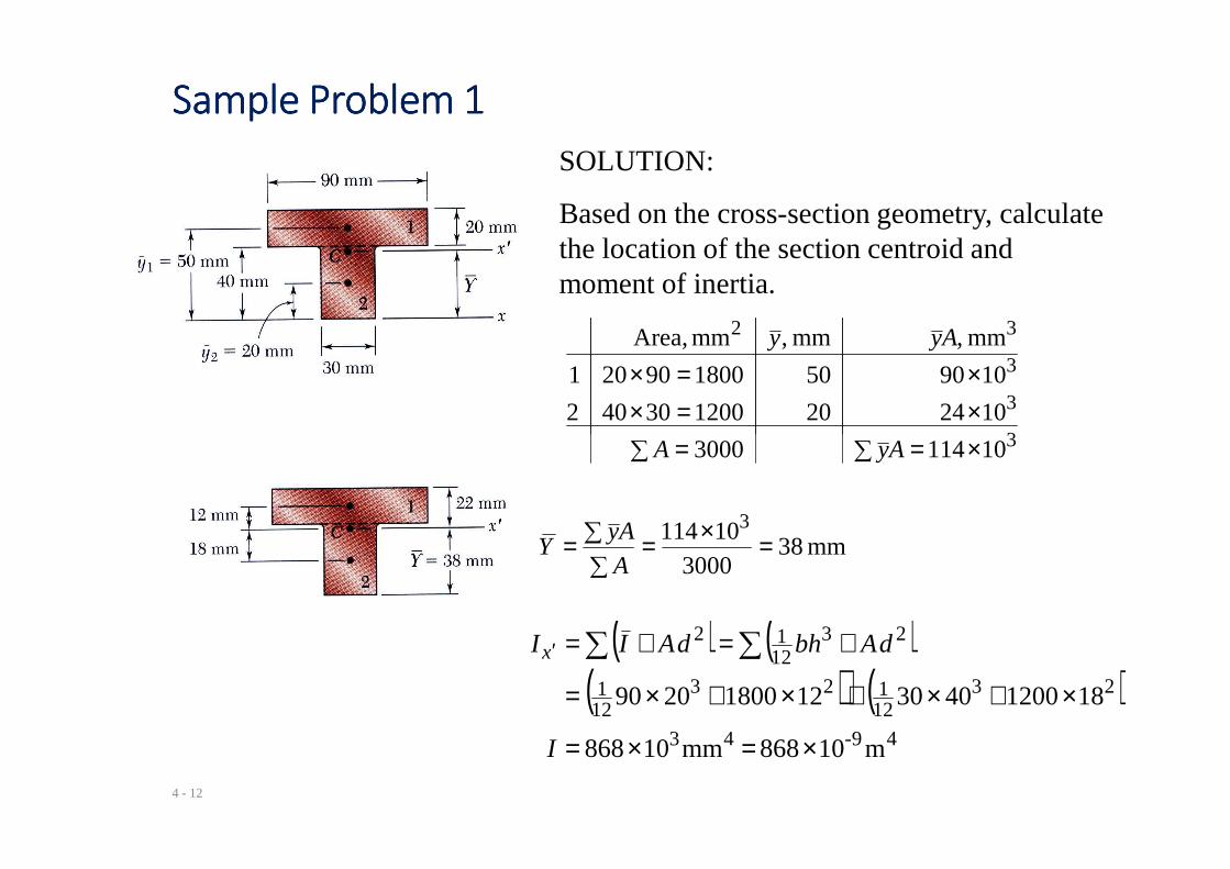
SOLUTION:
• Based on the cross-section geometry, calculate the location of the section centroid and moment of inertia.
( )∑ +=∑
∑= ′2dAII
A
AyY x
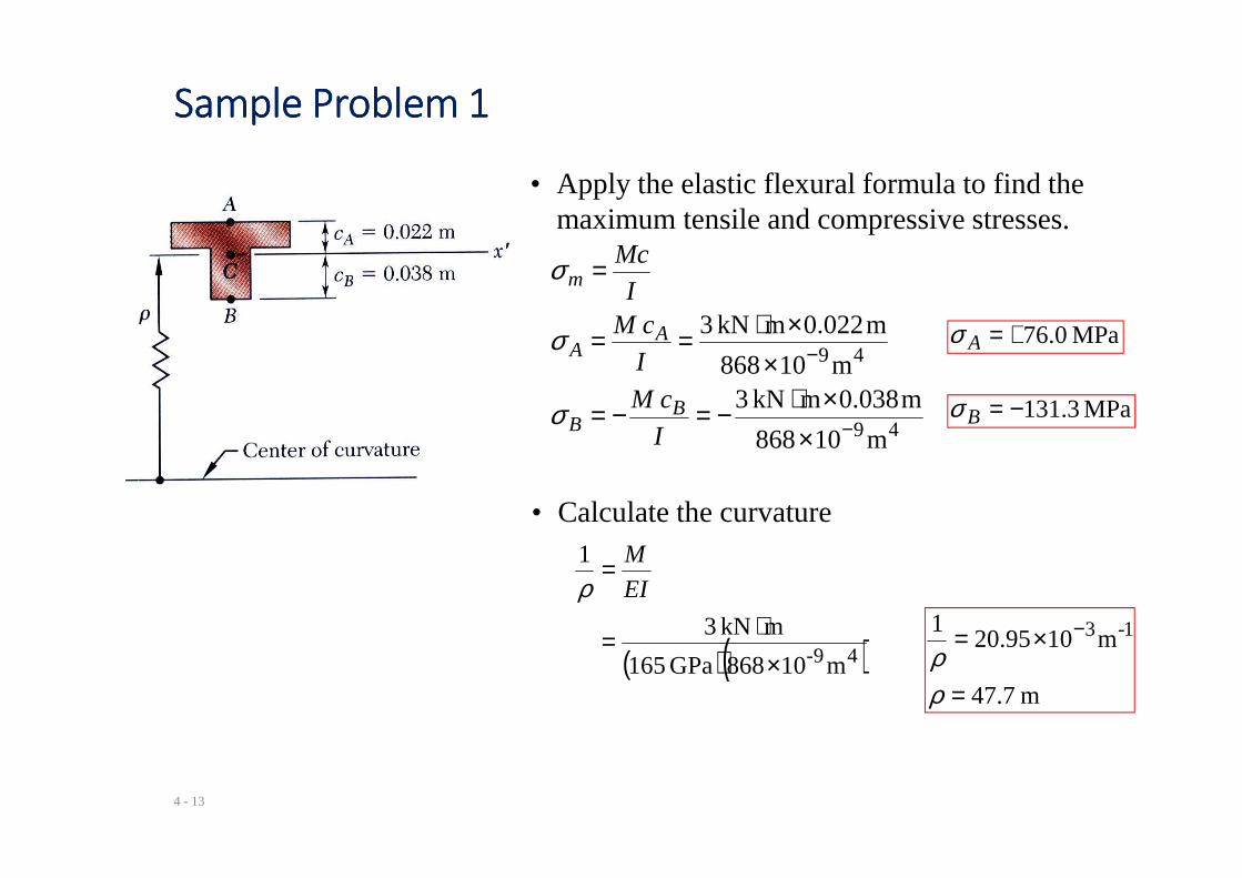
• Apply the elastic flexural formula to find the maximum tensile and
4 - 11
A cast-iron machine part is acted upon by a 3 kN-m couple. Knowing E = 165 GPa and neglecting the effects of fillets, determine (a) the maximum tensile and compressive stresses, (b) the radius of curvature.
find the maximum tensile and compressive stresses.
I
Mcm =σ
• Calculate the curvature
EI
M=ρ1
Sample Problem 1Sample Problem 1Sample Problem 1Sample Problem 1
SOLUTION:
Based on the cross-section geometry, calculate the location of the section centroid and moment of inertia.
∑ ×==∑
×=××=×
3
3
3
32
104220120030402
109050180090201
mm ,mm ,mm Area, Ayy
4 - 12
mm 383000
10114 3=×=
∑
∑=A
AyY
∑ ×==∑ 3101143000 AyA
( ) ( )( ) ( )
49-43
2312123
121
231212
m10868 mm10868
18120040301218002090
×=×=
×+×+×+×=
+=+= ∑∑′
I
dAbhdAIIx
Sample Problem 1Sample Problem 1Sample Problem 1Sample Problem 1
• Apply the elastic flexural formula to find the maximum tensile and compressive stresses.
49
49
m10868
m038.0mkN 3m10868
m022.0mkN 3
−
−
××⋅−=−=
××⋅==
=
I
cM
I
cMI
Mc
BB
AA
m
σ
σ
σ
MPa 0.76+=Aσ
MPa 3.131−=Bσ
4 - 13
49m10868 −×I
• Calculate the curvature
( )( )49- m10868GPa 165
mkN 3
1
×⋅=
=EI
M
ρ
m 7.47
m1095.201 1-3
=
×= −
ρρ
Bending of Members Made of Several MaterialsBending of Members Made of Several MaterialsBending of Members Made of Several MaterialsBending of Members Made of Several Materials
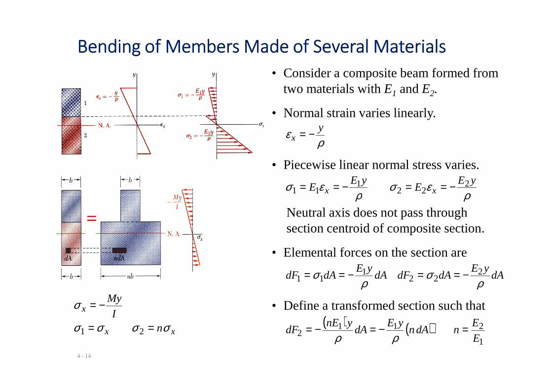
• Consider a composite beam formed from two materials with E1 and E2.
• Normal strain varies linearly.
ρε y
x −=
• Piecewise linear normal stress varies.
ρεσ
ρεσ yE
EyE
E xx2
221
11 −==−==
4 - 14
ρρ xx 2211
Neutral axis does not pass through section centroid of composite section.
• Elemental forces on the section are
dAyE
dAdFdAyE
dAdFρ
σρ
σ 222
111 −==−==
( ) ( )1
2112 E
EndAn
yEdA
ynEdF =−=−=
ρρ
• Define a transformed section such that
xx
x
nI
My
σσσσ
σ
==
−=
21
Example 1Example 1Example 1Example 1
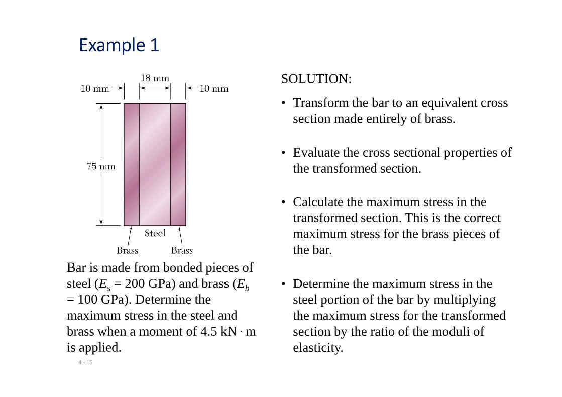
SOLUTION:
• Transform the bar to an equivalent cross section made entirely of brass.
• Evaluate the cross sectional properties of the transformed section.
• Calculate the maximum stress in the
4 - 15
Bar is made from bonded pieces of steel (Es = 200 GPa) and brass (Eb
= 100 GPa). Determine the maximum stress in the steel and brass when a moment of 4.5 kN . m is applied.
• Calculate the maximum stress in the transformed section. This is the correct maximum stress for the brass pieces of the bar.
• Determine the maximum stress in the steel portion of the bar by multiplying the maximum stress for the transformed section by the ratio of the moduli of elasticity.
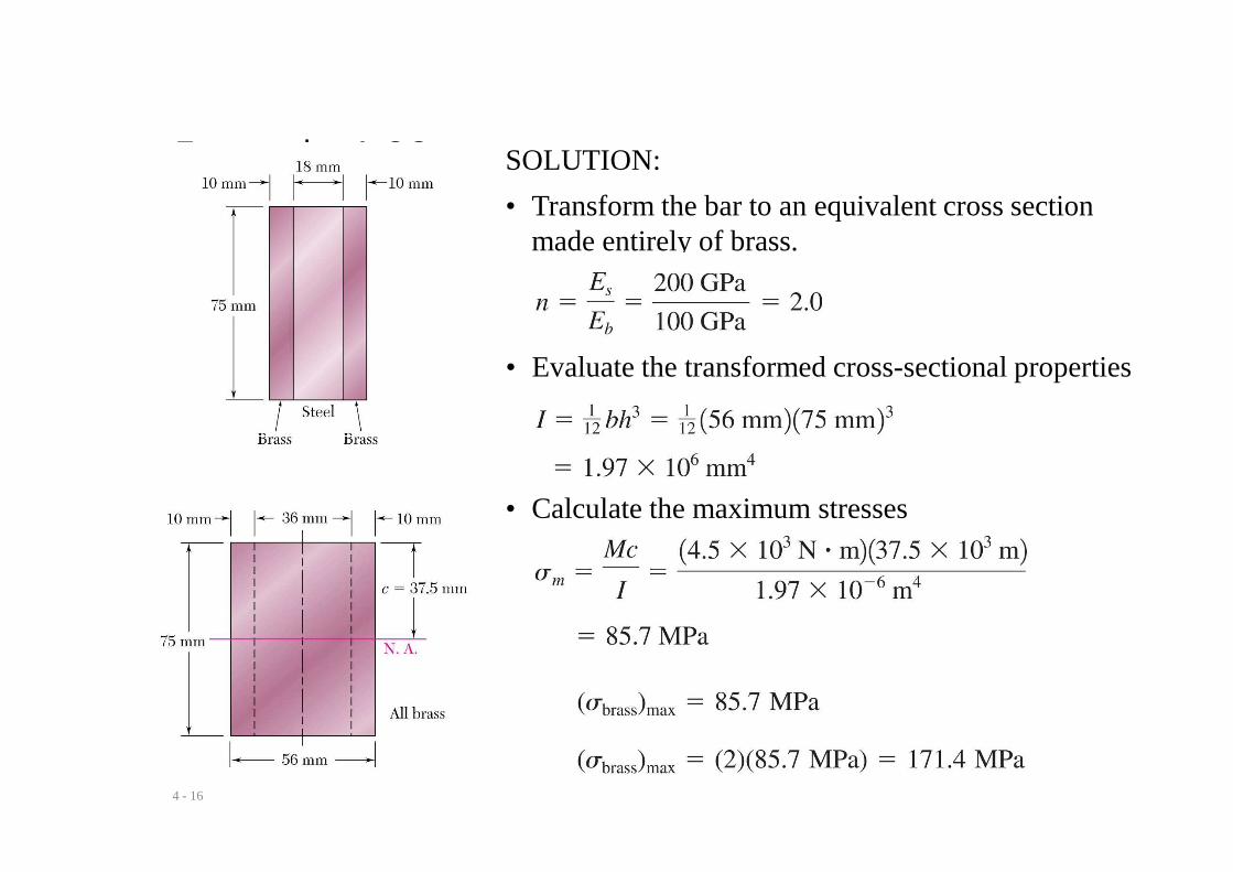
Example 4.03 SOLUTION:
• Transform the bar to an equivalent cross section made entirely of brass.
• Evaluate the transformed cross-sectional properties
4 - 16
• Calculate the maximum stresses
Reinforced Concrete BeamsReinforced Concrete BeamsReinforced Concrete BeamsReinforced Concrete Beams
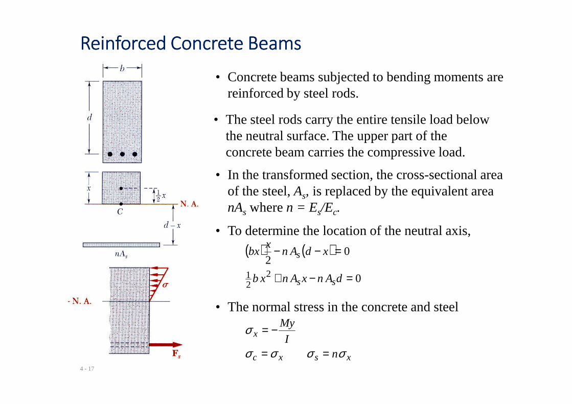
• Concrete beams subjected to bending moments are reinforced by steel rods.
• In the transformed section, the cross-sectional area of the steel, As, is replaced by the equivalent areanA where n = E /E .
• The steel rods carry the entire tensile load below the neutral surface. The upper part of the concrete beam carries the compressive load.
4 - 17
nAs where n = Es/Ec.
• To determine the location of the neutral axis,
( ) ( )
0
022
21 =−+
=−−
dAnxAnxb
xdAnx
bx
ss
s
• The normal stress in the concrete and steel
xsxc
x
nI
My
σσσσ
σ
==
−=
Sample Problem 2Sample Problem 2Sample Problem 2Sample Problem 2
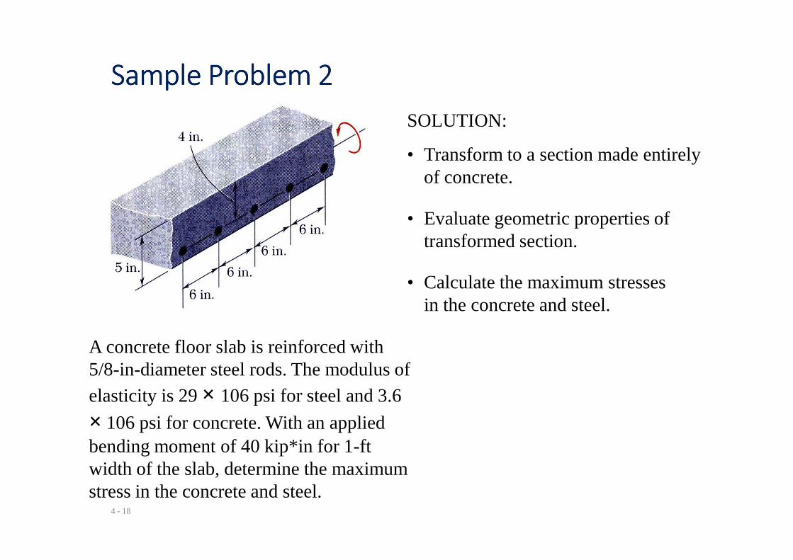
SOLUTION:
• Transform to a section made entirely of concrete.
• Evaluate geometric properties of transformed section.
• Calculate the maximum stresses
4 - 18
A concrete floor slab is reinforced with 5/8-in-diameter steel rods. The modulus of elasticity is 29 × 106 psi for steel and 3.6
× 106 psi for concrete. With an applied bending moment of 40 kip*in for 1-ft width of the slab, determine the maximum stress in the concrete and steel.
• Calculate the maximum stresses in the concrete and steel.
Sample Problem 2Sample Problem 2Sample Problem 2Sample Problem 2
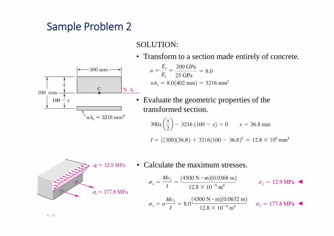
SOLUTION:
• Transform to a section made entirely of concrete.
• Evaluate the geometric properties of the transformed section.
4 - 19
• Calculate the maximum stresses.
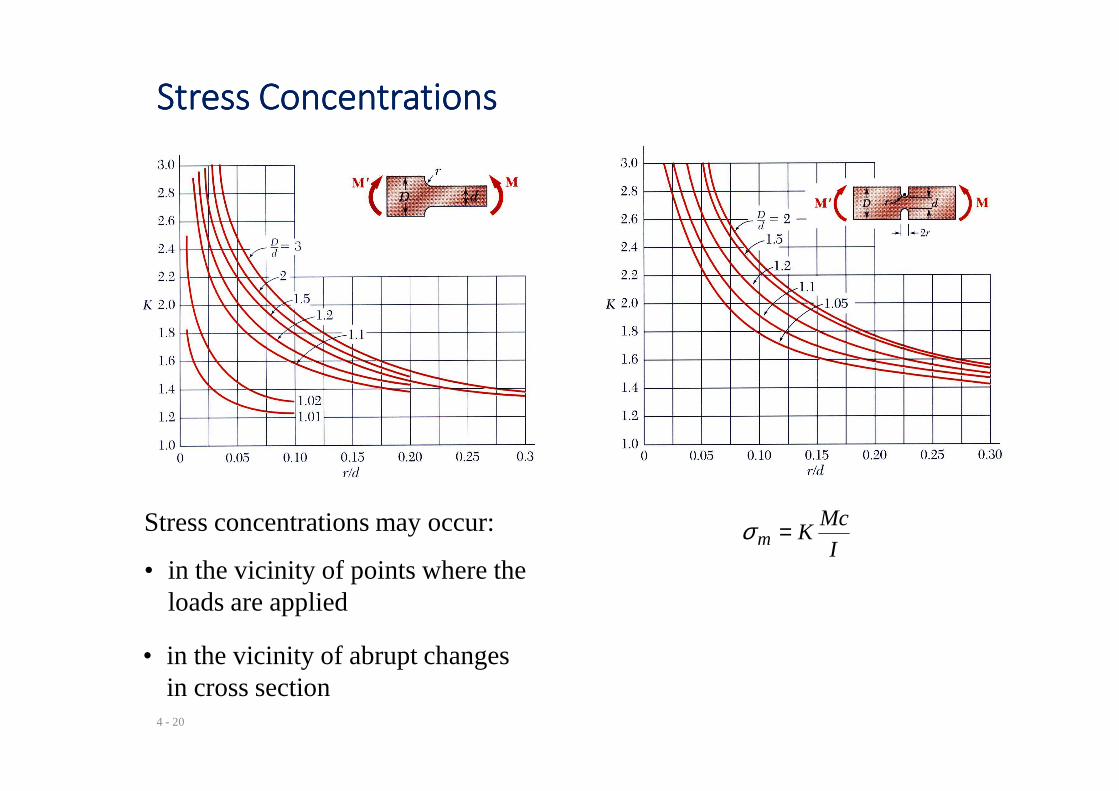
Stress ConcentrationsStress ConcentrationsStress ConcentrationsStress Concentrations
4 - 20
Stress concentrations may occur:
• in the vicinity of points where the loads are applied
I
McKm =σ
• in the vicinity of abrupt changes in cross section
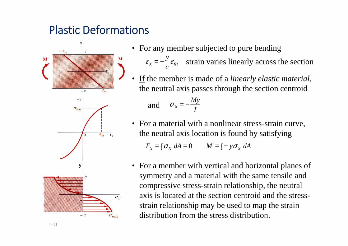
Plastic DeformationsPlastic DeformationsPlastic DeformationsPlastic Deformations
• For any member subjected to pure bending
mx c
y εε −= strain varies linearly across the section
• If the member is made of a linearly elastic material, the neutral axis passes through the section centroid
I
Myx −=σand
• For a material with a nonlinear stress-strain curve,
4 - 21
• For a material with a nonlinear stress-strain curve, the neutral axis location is found by satisfying
∫−=∫ == dAyMdAF xxx σσ 0
• For a member with vertical and horizontal planes of symmetry and a material with the same tensile and compressive stress-strain relationship, the neutral axis is located at the section centroid and the stress-strain relationship may be used to map the strain distribution from the stress distribution.
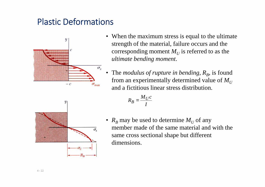
Plastic DeformationsPlastic DeformationsPlastic DeformationsPlastic Deformations
• When the maximum stress is equal to the ultimate strength of the material, failure occurs and the corresponding moment MU is referred to as the ultimate bending moment.
• The modulus of rupture in bending, RB, is found from an experimentally determined value of MU
and a fictitious linear stress distribution.
4 - 22
I
cMR U
B =
• RB may be used to determine MU of any member made of the same material and with the same cross sectional shape but different dimensions.
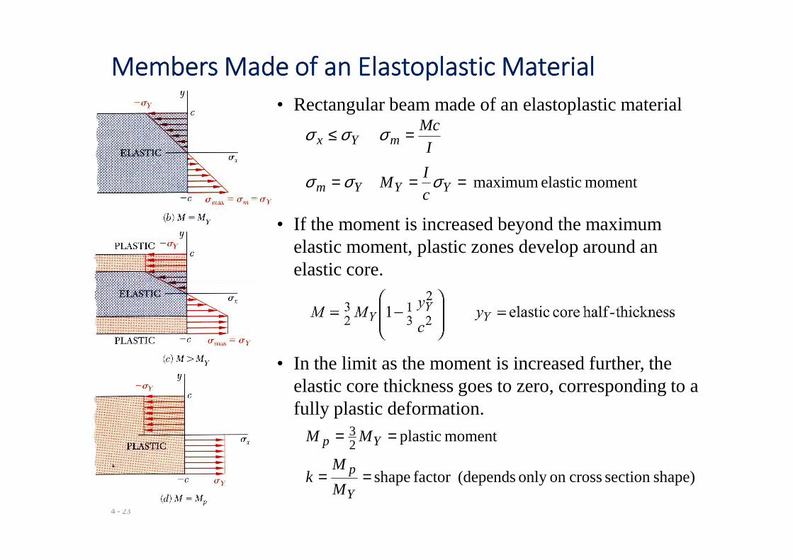
Members Made of an Elastoplastic MaterialMembers Made of an Elastoplastic MaterialMembers Made of an Elastoplastic MaterialMembers Made of an Elastoplastic Material
• Rectangular beam made of an elastoplastic material
moment elastic maximum ===
=≤
YYYm
mYx
c
IM
I
Mc
σσσ
σσσ
• If the moment is increased beyond the maximum elastic moment, plastic zones develop around an elastic core.
4 - 23
• In the limit as the moment is increased further, the elastic core thickness goes to zero, corresponding to a fully plastic deformation.
shape)section crosson only (dependsfactor shape
moment plastic 23
==
==
Y
p
Yp
M
Mk
MM


![MOMENT-CURVATURE DIAGRAMS FOR EVALUATION OF … · 2016-06-09 · for pure bending or bending moment and axial load is consid-ered the same [3]. The curvature for state II, bending](https://static.fdocuments.us/doc/165x107/5e56bfe4ea976d568d0a479d/moment-curvature-diagrams-for-evaluation-of-2016-06-09-for-pure-bending-or-bending.jpg)