Purchasing and Materials Management Division Elena Caruso ...
24
Tender Call No. 314-2016 – Addendum No. 4 Solid Waste Management Services- Brock West Closed Landfill Gas Flare System, Administration Building and Services Michael Pacholok, Chief Purchasing Official and Director Purchasing and Materials Management Division City Hall, 18th Floor, West 100 Queen Street West Toronto, Ontario M5H 2N2 Elena Caruso Manager Goods & Services January 5, 2017 VIA INTERNET POSTING 3 pages + attachments ADDENDUM NO. 4 Tender Call No. 314-2016 Contract No. 16ECS-Ml-08SW Re: Brock West Closed Landfill Gas Flare System, Administration Building and Services, Solid Waste Management Services Closing Date: January 13, 2017, 12:00 O'clock (Noon) Local Time Please refer to the above Tender document in your possession and be advised of the following: 1. REVISIONS: Continued from Addendum No. 3 R7. Replace Section 13610 with the attached. R8. Replace Section 15831 with the attached. R9. Replace the following drawings with the attached: 1670-2016-05-25 M3 1670-2016-05-28 E2 1670-2016-05-31 E5 1670-2016-05-37 E11 1670-2016-05-39 E13 R10. Replace Schedule of Prices to Cover Alterations, Extras or Deductions with the attached. 2. QUESTIONS & ANSWERS: Continued from Addendum No. 3 Q6. Could you please forward the following questions to the appropriate office? 1. Ref Section 13610: a. 1.6.B – I would like to make a correction to the model number mentioned in the spec. The model number for Raco Alarmagent should be 920AA-102DCRT. b. 1.6.L – The 3-year service agreement required for the above model would be Standard Realtime Service agreement with Model Number: 940AA-S3yrRT.
Transcript of Purchasing and Materials Management Division Elena Caruso ...

Tender Call No. 314-2016 – Addendum No. 4
Solid Waste Management Services- Brock West Closed Landfill Gas Flare System, Administration Building and Services
Michael Pacholok, Chief Purchasing Official and Director
Purchasing and Materials Management Division City Hall, 18th Floor, West 100 Queen Street West Toronto, Ontario M5H 2N2
Elena Caruso Manager Goods & Services
January 5, 2017 VIA INTERNET POSTING
3 pages + attachments
ADDENDUM NO. 4
Tender Call No. 314-2016 Contract No. 16ECS-Ml-08SW
Re: Brock West Closed Landfill Gas Flare System, Administration Building and Services, Solid Waste Management Services
Closing Date: January 13, 2017, 12:00 O'clock (Noon) Local Time
Please refer to the above Tender document in your possession and be advised of the following:
1. REVISIONS: Continued from Addendum No. 3
R7. Replace Section 13610 with the attached.
R8. Replace Section 15831 with the attached.
R9. Replace the following drawings with the attached:
1670-2016-05-25 M3
1670-2016-05-28 E2
1670-2016-05-31 E5
1670-2016-05-37 E11
1670-2016-05-39 E13
R10. Replace Schedule of Prices to Cover Alterations, Extras or Deductions with the attached.
2. QUESTIONS & ANSWERS: Continued from Addendum No. 3 Q6. Could you please forward the following questions to the appropriate office?
1. Ref Section 13610:
a. 1.6.B – I would like to make a correction to the model number mentioned in the
spec. The model number for Raco Alarmagent should be 920AA-102DCRT.
b. 1.6.L – The 3-year service agreement required for the above model would be
Standard Realtime Service agreement with Model Number: 940AA-S3yrRT.

Tender Call No. 314-2016 – Addendum No. 4
Solid Waste Management Services- Brock West Closed Landfill Gas Flare System, Administration Building and Services
A6. Refer to R7. A real time service package is not required.
Q7. Ref Section 13610 1.6.J – As per DWG E11, Raco Autodialer is located indoors. The
supplier code mentioned in the spec (820AA-YAEC1830) is also an antenna kit for indoor
mounted unit. Could you please change the “outdoor antenna kit” to “indoor antenna kit”.
A7. Refer to R7. Q8. Clarification required regarding the hazardous area classification both external and internal
to the landfill gas analyzer.
As the required landfill gas analyzer will contain an internal source of flammable gas (Methane),
the analyzer enclosure interior shall be considered a Class 1 Division 2 (Zone 2) hazardous area
(Reference: NFPA 496 Chapter 8) and as such appropriate protection to prevent flame &
explosion egress must be provided in the event of an internal leak. Table 8.2.3 (NFPA 496)
describes the protective method requirements dependent on the hazardous area classification
both external and internal to the analyzer.
A8. The landfill gas analyzer is located within the fan room which is a rated space (Class 1, Zone 2, Group IIA). There is also gas leak detection specified for the analyzer. Please respond if further clarification is required. Q9. Please provide specification for the 10kw Unit Heaters
A9. Refer to R9.
Q10. Please confirm that the incoming O/H conductor for the Fan House is to remain. Drawing
E5 has a note to replace existing O/H conductor.
A10. Refer to R9, Drawing E5. Refer to R10, revised Schedule of Prices to Cover Alterations, Extras or Deductions.
Please attach this addendum to your Tender document and be governed accordingly.
Bidders must acknowledge receipt of all addenda on the space provided on the Tender Call
Cover Page as per the Process Terms and Conditions, Section 1, Item 8 - Addenda, of the
Tender Call document. All other aspects of the Tender remain the same.
Should you have any questions regarding this addendum, contact Ted Justin, Senior Buyer at
(416) 338-5578, email [email protected].

Tender Call No. 314-2016 – Addendum No. 4
Solid Waste Management Services- Brock West Closed Landfill Gas Flare System, Administration Building and Services
Yours truly,
Robert Babin
Supervisor, Goods & Services
Purchasing and Materials Management

Section 4 Technical Specifications Tender Call No. 314-2016 Contract No. 16ECS-MI-02SW
11111387-2 November 4, 2016 SECTION 13610 Page 4-199
SECTION 13610 - SUMMARY OF CONTROL AND INSTRUMENTATION WORK
PART 1 GENERAL ............................................................................................................................. 203
PART 2 PRODUCTS (NOT USED) .................................................................................................... 206
PART 3 EXECUTION (NOT USED) ................................................................................................... 206

Section 4 Technical Specifications Tender Call No. 314-2016 Contract No. 16ECS-MI-02SW
11111387-2 November 4, 2016 SECTION 13610 Page 4-200
SECTION 13610
SUMMARY OF CONTROL AND INSTRUMENTATION WORK
PART 1 GENERAL
1.1 EXAMINATION
A. Review Contract Documents to identify electrical equipment, control and instrumentation components, etc. provided by other Divisions and/or CITY, but installed under Division 13.
B. Examine the Drawings and Specifications; visit the Site to ascertain that the Works can be carried out satisfactorily without changes to the Contract Documents.
C. If anything in the Contract Documents interferes with execution of the Works and intent of the Project, or does not comply with applicable codes and regulations, inform CONTRACT ADMINISTRATOR immediately in writing.
1.2 SCOPE OF WORK
A. Provide all equipment, labour, material, tools, supervision, and associated work as necessary to execute the Works and to realize the intent of the Project.
B. In general, but not limited to, the scope of work includes:
C. Replacement of the existing enclosed flare system complete with landfill gas blower and associated flare control panels.
D. Installation of the new control network.
1.3 ENCLOSED FLARE SYSTEM
A. The Landfill Gas Blower and Enclosed Flare System components will be provided by the Flare System Supplier. The Landfill Gas Blower and Enclosed Flare System consists of the enclosed flare, process (mechanical) equipment, and associated control and instrumentation devices. Process equipment, control panel, instrumentation, control and field devices will be free issued as individual components by the Flare System Supplier and they will require complete installation. Refer to the process and instrumentation drawings, packaged systems specifications, preliminary information for details related control, and instrumentation.
B. The control and instrumentation works shall include installation (mounting of devices, support, assembly, process connection, raceways, interconnection and wiring, network connection) of the flare system including provisions of cables, wires and raceways, underground duct bank, field wiring from equipment control panel system to the field equipment and ancillary devices, testing, etc. based on the documentation provided by system manufacturer. The Drawings provide only overview and location of the packaged system.
C. Provide and install new raceways and control wiring between flare control panel, new master control panel, and related control and instrumentation devices as indicated on the Drawings.

Section 4 Technical Specifications Tender Call No. 314-2016 Contract No. 16ECS-MI-02SW
11111387-2 November 4, 2016 SECTION 13610 Page 4-201
D. Provide installation acceptance tests for packaged equipment.
E. System Supplier shall provide Programmable Logic Controller (PLC) and Electronic Operator Interface (EOI) programming.
F. Refer to Sections 11560 Landfill Gas Blower and Enclosed Flare System, and 11570 Landfill Gas Control Facility for details.
1.4 REPLACEMENT OF THE EXISTING FLARE CONTROL SYSTEM
A. Decommission and remove all wiring for existing systems including gas blower and flare system, Identify control circuits to be restored.
B. The key components of the existing Flare Control System include: 1. Burner Starter panel. 2. Blower Fan Starter Panel. 3. Honeywell Instrument Panel. 4. Interface with ambient gas monitoring (detection) system. 5. Ventilation control.
C. Field investigation: 1. Limited information related to flare control systemis available. 2. Allow time and identify wiring before decommissioning of any device or component. 3. Document findings (make sketches, interconnection/wiring diagrams, mark up drawings,
etc.) to identify existing wiring to allow complete system restoration.
D. Provide detailed design, documentation, supply components, assemble, build, and install new control panel. Incorporate process equipment, instrumentation, miscellaneous plant/building related systems as indicated. The key components of the new Master Control Panel shall include: 1. Interface with Landfill Gas Bower and Enclosed Flare System. 2. Interface with autodialer and data recorder. 3. Plant shutdown system. 4. Interface with landfill gas analyzer. 5. Interface with ambient gas detection system. 6. Ventilation control. 7. Interface with security system.
E. Relocate devices and instruments from existing system and intended to be reused for the new Master Control Panel as indicated on the Drawings.
F. Provide new raceways, control and power wiring for related systems and reconnect to the new Master Control Panel as indicated on the Drawings.
G. Provide testing in accordance with Section 13623.
1.5 TELEPHONE SYSTEM
A. Identify and decommission existing circuits.
B. Install new Autodialer as described in the following article.

Section 4 Technical Specifications Tender Call No. 314-2016 Contract No. 16ECS-MI-02SW
11111387-2 November 4, 2016 SECTION 13610 Page 4-202
C. Provide and install new backboard, and relocate existing telecommunication equipment and wiring (patch panels, telephone receptacles, telephone, etc.).
D. Provide new circuits for: 1. Telephone receptacle. 2. Security system. 3. Autodialer.
1.6 AUTODIALER
A. Description: Wireless Remote Terminal Unit (WRTU), web-based alarm detection and notification system with around the clock status access from any internet connected device.
B. Manufacturer and Model No: AlarmAgent by Raco, Model number No. 900AA-102DCRTG substitutions shall be considered for this equipment.
C. Web Interface: System shall be capable of permitting direct user on demand management of the following functions: system preferences, users, reporting parameters and report generation.
D. System shall be capable of operating in real-time mode. This allows the WRTU to report in constant stream all sampled measured data that users require from the system. This data includes all I/O states, incoming power conditions and battery charging and voltage levels.
E. Cellular Communications: Operation of the WRTU shall not require a service contract with local cellular carriers.
F. Inputs: The AutoDialer will have a minimum of eight digital inputs. All inputs shall be dry-type (unpowered), opto-isolated an surge protected. All digital inputs shall use a single common return Input signals to be monitored in the blower enclosure are: 1. Blower Status (On / Off) 2. Blower High Temperature (Alarm) 3. Methane Gas Detection (Alarm) 4. Power Failure (Alarm) 5. Low Backup Battery (Alarm).
G. Universal Inputs: In additional to the above digital inputs, the autodialer shall have a minimum of two universal (analog) inputs capable of reading 4 – 20 mA signals of 10 bit (0.125%) resolution. The signals shall be single ended and surge protected. Loop resistance shall be nominally 250 ohm. 1. Independent high and low setpoints shall be provided for each analog input. 2. The two analog inputs shall be user-configurable to serve as additional digital inputs in
lieu of analog, without need for physical settings at the WRTU.
H. Outputs: Two normally-open, output relays shall be provided. The output relays shall have the following characteristics: 1. Contacts are to rated 0.5 A at 120 VAC. 2. WRTU shall provide the ability to remotely open and close one or both unit relays on a
scheduled basis.
I. Alarm Trip Delay: all alarm inputs shall have individually assigned alarm trip delay settings. The range shall be two seconds to one hour.

Section 4 Technical Specifications Tender Call No. 314-2016 Contract No. 16ECS-MI-02SW
11111387-2 November 4, 2016 SECTION 13610 Page 4-203
J. Antenna: WRTU to include outdoor antenna kit (Supplier code: 820AA-PAEC1830)
K. LED Indicators: LED indicators shall be provided for both performance and diagnostic conditions as follows: 1. Performance Indicators:
a. WRTU On / Off. b. WRTU Armed / Disarmed. c. Battery Charge State. d. Transmitting State (indicating data communication with central system). e. Continuous Signal Strength Indicator (to provide indication of strength of radio
signal). 2. Diagnostic Indicators:
a. Input State of each digital input. b. Primary Power present. c. Output Relays activated. d. Radio Status. e. Account Status. f. Alarm Status. g. Violation Status. h. Suspended Status. i. Test Button Ready Status.
L. Service Plan: A three year service agreement (Supplier Code 840AA-S3yr) shall be issued in the name of the CITY as part of this work.
1.7 INSTRUMENTATION
A. Provide instruments and devices in accordance with Section 13420.
B. Provide new raceways and wiring, and connect to the Master Control Panel.
1.8 SECURITY SYSTEM
A. Include the provision of a security system complete with door access control stations, and associated wiring to be integrated into the Master Control Panel. Refer to the Contract Drawings for details of the signaling requirements.
1.9 AMBIENT GAS DETECTION SYSTEM
A. Generally, existing system shall not require modifications; however associated works shall include new hardwired interface with new Master Control Panel.
PART 2 PRODUCTS (NOT USED)
PART 3 EXECUTION (NOT USED)
END OF SECTION

Section 4 Technical Specifications Tender Call No. 314-2016 Contract No. 16ECS-MI-02SW
11111387-2 November 4, 2016 SECTION 15831 Page 4-226
SECTION 15831 - HVAC FANS
PART 1 GENERAL ............................................................................................................................. 227
PART 2 PRODUCTS .......................................................................................................................... 228
PART 3 EXECUTION .......................................................................................................................... 231

Section 4 Technical Specifications Tender Call No. 314-2016 Contract No. 16ECS-MI-02SW
11111387-2 November 4, 2016 SECTION 15831 Page 4-227
SECTION 15831
HVAC FANS
PART 1 GENERAL
1.1 SECTION INCLUDES
A. Downblast centrifugal roof fans.
B. Duct blowers or cabinet fans.
1.2 REFERENCES
A. American Bearing Manufacturers Association: 1. ABMA 9 - Load Ratings and Fatigue Life for Ball Bearings. 2. ABMA 11 - Load Ratings and Fatigue Life for Roller Bearings.
B. Air Movement and Control Association International, Inc.: 1. AMCA 99 - Standards Handbook. 2. AMCA 204 - Balance Quality and Vibration Levels for Fans. 3. AMCA 210 - Laboratory Methods of Testing Fans for Aerodynamic Performance Rating. 4. AMCA 300 - Reverberant Room Method for Sound Testing of Fans. 5. AMCA 301 - Methods for Calculating Fan Sound Ratings from Laboratory Test Data.
C. American Refrigeration Institute: 1. ARI 1060 - Air to Air Energy Recovery Ventilation Equipment Certification Equipment
Program.
D. ASTM International: 1. ASTM E1996 - Standard Specification for Performance of Exterior Windows, Curtain
Walls, Doors and Impact Protective Systems Impacted by Windborne Debris in Hurricanes.
E. National Electrical Manufacturers Association: 1. NEMA MG 1 - Motors and Generators. 2. NEMA 250 - Enclosures for Electrical Equipment (1000 Volts Maximum).
F. Underwriters Laboratories Inc.: 1. UL 705 - Power Ventilators.
1.3 SUBMITTALS
A. Product Data: Submit data on each type of fan and include accessories, fan curves with specified operating point plotted, power, RPM, sound power levels for both fan inlet and outlet at rated capacity, electrical characteristics, and connection requirements.
B. Shop Drawings: Indicate size and configuration of fan assembly, mountings, weights, ductwork and accessory connections.

Section 4 Technical Specifications Tender Call No. 314-2016 Contract No. 16ECS-MI-02SW
11111387-2 November 4, 2016 SECTION 15831 Page 4-228
C. Manufacturer's Instructions: Submit fan manufacturer's instructions.
D. Manufacturer's Certificate: Certify that products meet or exceed specified requirements.
1.4 CLOSEOUT SUBMITTALS
A. Operation and Maintenance Data: Submit instructions for lubrication, motor and drive replacement, spare parts list, and wiring diagrams.
B. Warranties: Completed original warranty forms filled out in CITY's name and registered with manufacturer.
1.5 QUALITY ASSURANCE
A. Performance Ratings: Conform to AMCA 210.
B. Sound Ratings: AMCA 301, tested to AMCA 300.
C. UL Compliance: UL listed and labeled, designed, manufactured, and tested according to UL 705.
D. Balance Quality: Conform to AMCA 204.
1.6 QUALIFICATIONS
A. Manufacturer: Company specializing in manufacturing products specified in this Section with minimum 3 years of documented experience.
B. Installer: Company specializing in performing the work of this Section with minimum 3 years of documented experience.
1.7 DELIVERY, STORAGE, AND HANDLING
A. Protect motors, shafts, and bearings from weather and construction dust.
1.8 WARRANTY
A. Furnish 3 year manufacturer's warranty for fans.
PART 2 PRODUCTS
2.1 CENTRIFUGAL ROOF FANS
A. Tag: BWL-LFG-EF-002
B. Manufacturers:

Section 4 Technical Specifications Tender Call No. 314-2016 Contract No. 16ECS-MI-02SW
11111387-2 November 4, 2016 SECTION 15831 Page 4-229
1. Greenheck Fan Corporation, Model G/CUE. 2. Twin City Fan & Blower, Model DCRD/BCRU. 3. Or approved equivalent
C. Fan Unit: Downblast or Upblast roof exhaust type, direct drive, with spun aluminum housing; resilient mounted motor; aluminum wire bird screen; square base to suit roof curb with continuous curb gaskets.
D. Sheaves: Cast iron or steel, dynamically balanced, bored to fit shafts and keyed; variable and adjustable pitch motor sheave selected so required rpm is obtained with sheaves set at mid position; fan shaft with self aligning pre lubricated ball bearings.
E. Motor: Totally enclosed fan cooled , brushless DC type, ¼ hp, 120 volt, single phase, 60 Hz motor,
F. Roof Curb: Provide 300 mm high aluminum constructed roof curb with continuously welded seams to suit existing 300mm by 300 mm roof opening.
G. Disconnect Switch: Factory wired, non fusible, in fan housing for thermal overload protected motor, NEMA 250 enclosure.
H. Accessories: 1. Motor Operated Damper: Aluminum multiple blade construction, felt edged with offset
hinge pin, nylon bearings, blades linked and 120 voltage motor drive, power open, spring return.
2. 550 mm x 550 mm, aluminum eggcrate face exhaust grill with 3.11 square feet core area, model EH Price 85 Series.
3. Aluminum insect screen. 4. Wall-mounted thermostat.
I. Performance: 1. Air Flow: 542 L/s (1,150 CFM). 2. Static Pressure: 70 Pa (0.278 inch wg). 3. Fan RPM: 1725.
J. Electrical Characteristics and Controls: 1. Electrical Characteristics:
a. 1/4 hp b. 120 volt (V), single phase, 60 Hz. c. Constant speed motor
2. Controls: a. Fan to be controlled by wall-mounted thermostat:
1) Fan is normally off. 2) Fan will be enabled if temperature in the Electrical Room reaches set
temperature. 3) Set temperature at 37 °C.
b. Fan to interlock with associated actuated damper and existing side wall mounted louver actuated dampers.
c. Fan to be controlled by methane gas detection system: 1) Fan will be enabled if methane gas is detected in the Electrical Room
regardless of room temperature.
Section 4 Technical Specifications Tender Call No. 314-2016 Contract No. 16ECS-MI-02SW
11111387-2 November 4, 2016 SECTION 15831 Page 4-230
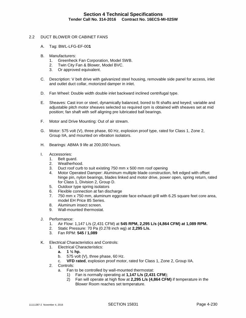
2.2 DUCT BLOWER OR CABINET FANS
A. Tag: BWL-LFG-EF-001
B. Manufacturers: 1. Greenheck Fan Corporation, Model SWB. 2. Twin City Fan & Blower, Model BVC. 3. Or approved equivalent.
C. Description: V belt drive with galvanized steel housing, removable side panel for access, inlet and outlet duct collar, motorized damper in inlet.
D. Fan Wheel: Double width double inlet backward inclined centrifugal type.
E. Sheaves: Cast iron or steel, dynamically balanced, bored to fit shafts and keyed; variable and adjustable pitch motor sheaves selected so required rpm is obtained with sheaves set at mid position; fan shaft with self aligning pre lubricated ball bearings.
F. Motor and Drive Mounting: Out of air stream.
G. Motor: 575 volt (V), three phase, 60 Hz, explosion proof type, rated for Class 1, Zone 2, Group IIA, and mounted on vibration isolators.
H. Bearings: ABMA 9 life at 200,000 hours.
I. Accessories: 1. Belt guard. 2. Weatherhood. 3. Duct roof curb to suit existing 750 mm x 500 mm roof opening 4. Motor Operated Damper: Aluminum multiple blade construction, felt edged with offset
hinge pin, nylon bearings, blades linked and motor drive, power open, spring return, rated for Class 1, Division 2, Group D.
5. Outdoor type spring isolators 6. Flexible connection at fan discharge 7. 750 mm x 750 mm, aluminum eggcrate face exhaust grill with 6.25 square feet core area,
model EH Price 85 Series. 8. Aluminum insect screen. 9. Wall-mounted thermostat.
J. Performance: 1. Air Flow: 1,147 L/s (2,431 CFM) at 545 RPM, 2,295 L/s (4,864 CFM) at 1,089 RPM. 2. Static Pressure: 70 Pa (0.278 inch wg) at 2,295 L/s. 3. Fan RPM: 545 / 1,089
K. Electrical Characteristics and Controls: 1. Electrical Characteristics:
a. 1 ½ hp. b. 575 volt (V), three phase, 60 Hz. c. VFD rated, explosion proof motor, rated for Class 1, Zone 2, Group IIA.
2. Controls: a. Fan to be controlled by wall-mounted thermostat:
1) Fan is normally operating at 1,147 L/s (2,431 CFM); 2) Fan will operate at high flow at 2,295 L/s (4,864 CFM) if temperature in the
Blower Room reaches set temperature.

Section 4 Technical Specifications Tender Call No. 314-2016 Contract No. 16ECS-MI-02SW
11111387-2 November 4, 2016 SECTION 15831 Page 4-231
3) Set temperature at 37 °C. b. Fan to interlock with associated actuated damper and existing side wall mounted
louver actuated dampers. c. Fan to be controlled by methane gas detection system:
1) Fan will operate at high flow at 2,295 L/s (4,864 CFM) if methane gas is detected in the Electrical Room regardless of room temperature.
PART 3 EXECUTION
3.1 EXAMINATION
A. Verify field measurements prior to installation.
B. Verify roof curbs dimensions with existing roof openings.
3.2 INSTALLATION
A. Provide safety screen where inlet or outlet is exposed.
B. Install in accordance with manufacturer's instructions.
C. Secure roof fans stainless steel lag screws to roof curb.
D. Install flexible connections between fan and ductwork. Ensure metal bands of connectors are parallel with minimum 1 inch (25 mm) flex between ductwork and fan while running.
E. Install and support duct sized to suit existing openings and roof fan dimensions.
F. Provide sheaves required for final air balance.
G. Adjust and balance air systems in accordance with standard procedures and recognized practices of the AABC or SMACNA.
3.3 ADJUSTING AND BALANCING AIR SIDE
A. Preparation: Prior to beginning the Works, perform the following activities: 1. Review Shop Drawings and installed system for adequate and accessible balancing
devices and test points. 2. Suggest to CONTRACT ADMINISTRATOR dampers that need to be added or replaced
in order to obtain proper air control. 3. Verify proper startup procedures have been completed on the system. 4. Verify controls installation is complete and system is in stable operation under automatic
control. 5. Verify test instruments have been calibrated to a recognized standard and are within
manufacturer's recommended calibration interval before beginning the Works.
B. General: 1. When adjustments are made to a portion of a fan system, reread other portions of that
same system to determine effects imposed by adjustments. Readjust as necessary. 2. Lock and mark final positions of balancing dampers with permanent felt pen.

Section 4 Technical Specifications Tender Call No. 314-2016 Contract No. 16ECS-MI-02SW
11111387-2 November 4, 2016 SECTION 15831 Page 4-232
3. Correct fan and airflow measurements for Site elevation.
C. Equipment Data: Collect the following data and included in final report: 1. Type of unit. 2. Equipment identification number. 3. Equipment nameplate data (including manufacturer, model, size, type, and serial
number). 4. Motor data (frame, kW, volts, FLA RPM, and service factor). 5. Sheave manufacturer, size, and bore. 6. Belt size and number. 7. Sheave centerline distance and adjustment limits. 8. Starter and motor overload protection data. 9. Include changes made during course of system balancing.
D. Fan Systems: 1. Measure fan system performance in accordance with AMCA 203. 2. In each system at least one air path from fan to final branch duct termination shall have
dampers fully open. Achieve final air quantities by adjusting fan speed. 3. Adjust Fan Air Volumes:
a. Adjust fan speeds and motor drives for required equipment air volumes, with allowable variation of plus 10 percent minus 0 percent.
b. After final adjustments, do not operate motor above nameplate amperage on any phase.
c. After final adjustments, do not operate fan above maximum rated speed. d. Perform airflow test readings under simulated or actual conditions of full cooling, full
heating, minimum outside air, full outside air and exhaust, and full return air. e. Provide and make drive and belt changes on motors or fans as required to adjust
equipment to specified conditions. Drives shall be able to deliver 150 percent of motor horsepower. Provide written notice to air handling unit manufacturer and CONTRACT ADMINISTRATOR if drive or belt changes were made.
4. Adjust outside air dampers, return air dampers, relief air dampers, exhaust air dampers, and motorized louvers for maximum and minimum air requirements.
5. Read and record static pressures at unit inlet and discharge, each filter set, coils, dampers, plenums, and mixing dual duct or adjustable volume boxes, on every supply, return, and exhaust fan for each test condition.
6. Read and record motor amperage on all phases for each test condition.
E. Air Inlets and Outlets: 1. In each system at least one air path from fan to final branch duct termination shall have
dampers fully open. 2. Adjust air volumes on exhaust grilles, to the quantity shown, with allowable variation of
plus or minus 10 percent. 3. After final adjustments are made secure dampers to prevent movement and mark final
positions with permanent felt pen.
F. Building Static Pressure: 1. Measure building static pressure relative to outside in perimeter entrances during normal
system conditions that would yield widest range in internal building pressure. 2. Adjust building static pressure control parameters to ensure perimeter entrances are
positive to outdoors by 12 Pa with entrance doors closed.

Section 4 Technical Specifications Tender Call No. 314-2016 Contract No. 16ECS-MI-02SW
11111387-2 November 4, 2016 SECTION 15831 Page 4-233
3.4 FIELD QUALITY CONTROL
A. Performance Testing: 1. Vibration Testing:
a. Upon completion of air system balance, perform vibration testing as specified below for rotating or reciprocating equipment.
2. Vibration Test Procedures: a. Take measurements at each bearing housing using a calibrated electronic analyzer. b. Record log shall include equipment symbol, location, identification, and peak to peak
displacement in a direction parallel to shaft in a horizontal plane, and in a direction perpendicular to shaft in both horizontal and vertical planes.
c. Maximum Peak to Peak Amplitude Levels:
Rotational Speed (rpm) Vibration Amplitude (mils)
250 3.5
500 2.0
750 1.5
1,000 1.0
1,500 0.75
3. Notify CONTRACT ADMINISTRATOR if amplitude exceeds upper limit specified. 4. After readjustment for vibration, measure and record only the readjusted equipment to
determine its conformance with design.
B. Balancing Log Report Requirements: 1. Include narrative description for each system explaining TAB methodology and
assumptions used. Clearly identify test conditions for tests performed. Include control setpoint.
2. Log and record operational information from every test for each system, as necessary to accomplish services described.
3. Include equipment data for units tested. 4. Include reduced set of HVAC drawings or system schematic diagrams with each element
uniquely identified and indexed to balance log. 5. Indicate recorded site values, and velocity and mass correction factors used to provide
equivalent standard air quantities. 6. Include separate section in log, if necessary, describing operating difficulties in air
systems that could not be eliminated by specified procedures. Identify these problems by system and location within building; include outline or summary of condition and its effect on building, and describe corrective actions attempted and recommended.
C. Quality Control Verification: After adjustments have been completed and balance logs submitted, balancing and testing agency shall be available to demonstrate the following: 1. Air balancing procedures, vibration tests, and verification of test results. 2. Perform spot tests on a maximum of 20 percent of total diffusers and grilles, and on two
air handling fan devices per building, with measuring equipment used in original tests, at random points selected by CONTRACT ADMINISTRATOR.
3. Results of these spot tests shall agree with balance logs within plus or minus 10 percent. Where this accuracy cannot be verified, rebalance portions of system as requested by CONTRACT ADMINISTRATOR.
4. At completion of rebalance procedures, perform another spot test if required to verify results.
Section 4 Technical Specifications Tender Call No. 314-2016 Contract No. 16ECS-MI-02SW
11111387-2 November 4, 2016 SECTION 15831 Page 4-234
3.5 CLEANING
A. Vacuum clean coils and inside of fan cabinet.
3.6 DEMONSTRATION
A. Demonstrate fan operation and maintenance procedures.
3.7 PROTECTION
A. Do not operate fans until ductwork is clean, filters in place, bearings lubricated, and fan has been test run under observation.
END OF SECTION

CONTRACT No.DRAFTING:
SCALE:
DATE:
DESIGN: CHECK:
NUMBER:DRAWING
SIGNEDINITIALREVISIONSDATENo.
Design & Construction - Major InfrastructureENGINEERING & CONSTRUCTION SERVICES
DIRECTORCarlyle Khan
AND ASSET MANAGEMENTDESIGN AND CONSTRUCTION
Bill De AngelisDIRECTOR
SOLID WASTE MANAGEMENT SERVICES
SOLID WASTE MANAGEMENT
INFRASTRUCTURE DEVELOPMENTMAJOR INFRASTRUCTURE
CLOSED BROCK WEST LANDFILL SITELANDFILL GAS FLARE SYSTEM, ADMINISTRATION BUILDING, AND SERVICES
FAN HOUSE ROOF PLAN - ROOF REPAIR PLANPLAN
1670-2016-05-24APRIL 2016
K.M. K.D. 16ES-MI-08SW
11111387-A(002)ME-WA004
M3
jmai
Call Out
EXPLOSION PROOF BACKWARD INCLINED EXHAUST BLOWER, 575V/3/60 HZ, 1.5 HP TEFC MOTOR, RATED FOR CLASS 1, DIV. II, GROUP D. BLOWER TO OPERATE AT 2431 CFM AT 0.12" W.G DURING NORMAL OPERATION. BLOWER TO OPERATE AT 4864 CFM AT 027" W.G. WHEN HIGH TEMPERATURE IS PRESENT IN THE BUILDING ( TRIGGERED BY THERMOSTAT) AND/OR HIGH METHANE GAS LEVEL IS DETECTED IN THE BUILDING. C/W WEATHER COVER AND INSECT SCREEN. MODEL: BCV-200 BY TWIN CITY FAN AND BLOWERS.
jmai
Call Out
NEW 30'X30" EGGRATE FACED INTAKE GRILL, 1/2" X 1/2" X 1/2" ALUMINUM GRID CORE, WHITE POWDER COATED, EH PRICE SERIES 80
jmai
Line
jmai
Line
jmai
Line
jmai
Line
jmai
Call Out
BWL-LFG-EF-001
jmai
Call Out
BWL-LFG-EF-002
jmai
Line
jmai
Line
jmai
Call Out
BWL-LFG-EF-001
jmai
Line
jmai
Line
jmai
Call Out
BWL-LFG-EF-002
jmai
Call Out
BWL-LFG-EF-002
jmai
Call Out
BWL-LFG-EF-001
jmai
Line
jmai
Line
jmai
Line
jmai
Call Out
MODEL & MANUFACTURER: EXUB BY REZNOR
jmai
Call Out
MODEL & MANUFACTURER: EXUB BY REZNOR
jmai
Call Out
BWL-LFG-EF-002
jmai
Call Out
BWL-LFG-EF-001
jmai
Call Out
BWL-LFG-EF-001
jmai
Call Out
GREENHECK ESJ-401
jmai
Call Out
GREENHECK ESJ-401


Section 3 – Tender Submission Package Revised Schedule of Prices (as per Addendum#4)
Tender Call No. 314-2016 Contract No.16ECS-M1-08SW
The Bidder also fills in the following Schedule of Prices to cover alterations, extras or deductions. The terms of this Schedule apply notwithstanding anything to the contrary in the Contract Documents.
REVISED SCHEDULE OF PRICES TO COVER ALTERATIONS, EXTRAS OR DEDUCTIONS
Item No
Description Provisional Quantity
Unit Unit Price Total Price
1
Administration building and appurtenances. Including non-potable water system, sanitary holding tank, and electrical and communication service. Includes demolition and removal of existing Administration buildings and abandonment of existing septic tank.
1 each $ _______
/ each $ ___________
2 Supply and Installation of Grassed Surfaces
150 m2 $ _______
/ m2 $ ___________
3 Supply and Installation of Asphalt Surface
150 m2 $ _______
/ m2 $ ___________
4 Disposal of Unsuitable Materials as Non Hazardous Waste (02317 3.5)
100 tonnes $ _______ / tonnes
$ ___________
5 Supply and install furniture and appliances.
1 each $ _______
/ each $20,000.00
6 Removal of existing and supply and installation of new overhead conductor to fan house.
18 m $ _______
/ m $ ___________
7 Contingency Allowance $320,000.00
8 GRAND TOTAL (Rows 1-6) $ ____________________________
(Carry forward to Page 3-7)
TOTAL ALLOWANCE FOR SCHEDULE OF PRICES TO COVER ALTERATIONS, EXTRAS OR DEDUCTIONS (EXCLUDING HST) The contingency and cash allowances listed in this Schedule are for potential Work which may be required beyond the scope of this Contract. The unit prices entered by the Bidder for the items listed in this Schedule shall be used by the City to determine payments for the Work where those Work items are ordered by the Contract Administrator, and shall also be used by the City to determine credits to the City from the Contractor where quantities ultimately required for unit price items under the base scope of the Contract are less than the original Contract

Section 3 – Tender Submission Package Revised Schedule of Prices (as per Addendum#4)
Tender Call No. 314-2016 Contract No.16ECS-M1-08SW
quantities. The unit prices in the schedule shall not include HST nor overhead and profit. The unit prices inserted above for provisional quantities shall be used to determine payment for those items or credits even if actual quantities are found to vary considerably from them. In accordance with CCDC-2 Part 4, the Contract Price includes the cash allowances and the Contract Price includes all overhead and profit for those allowances. Profit and overhead on cash allowance Work will be in addition to the figures in the Schedule and will be calculated in accordance with the Contract Documents. In accordance with CCDC-2 Part 4, the Contract Price includes the contingency allowance listed in this Schedule. The contingency allowance includes all overhead and profit in connection with Work undertaken under the contingency allowance. The Bidder agrees that no part of the cash allowances or contingency allowance shall be expended without written direction from the Consultant. Payments from the contingency allowance will be made only following issuance of a Change Order approved by the Consultant. Any unused portion of the contingency allowance and cash allowances, and any credits to the City for unit price items shall be deducted from the Contract Price. In the event of obvious mathematical errors in the Schedule of Prices, the unit prices tendered shall be considered correct and arithmetic extensions and totals shall be corrected accordingly. Any such corrections resulting in adjustment to the total for the Schedule of Prices will be similarly applied as an adjustment to the Total Lump Sum Price tendered for the project. Bidders that do not fully complete these forms (such as leaving lines blank), or have unclear answers (such as "n/a", "-", "tba" or "included" etc.) will be declared non-compliant. Prices that are intended to be zero cost/no charge to the city are to be submitted in the space provided in the price schedule as "$0.00" or "zero". Payment for Work not listed in this Schedule will be made in accordance with the Contract Documents. Taxes Harmonized Sales Tax (HST) is to be applied to the prices submitted as specified in the relevant sections of the call document or in the Price Schedule provided in the call.
HST for the supply and delivery of materials/goods are to be shown as additional separate line items on the Price Schedule and any subsequent invoice.