PUR 5-Gallon Pail Unloader EQUIPMENT MANUAL · Henkel Corp. PUR 5-Gallon Pail Unloader Pump Speed...
27
PUR 5-Gallon Pail Unloader EQUIPMENT MANUAL
Transcript of PUR 5-Gallon Pail Unloader EQUIPMENT MANUAL · Henkel Corp. PUR 5-Gallon Pail Unloader Pump Speed...
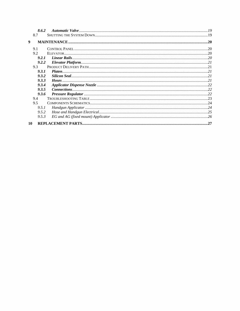
PUR 5-Gallon Pail Unloader
EQUIPMENT MANUAL
1 BACKGROUND ................................................................................................................................................4
2 PERSONNEL SAFETY.....................................................................................................................................4
3 MACHINE SAFETY .........................................................................................................................................4
4 LIST OF ASSEMBLIES SUPPLIED...............................................................................................................5
5 DESCRIPTION..................................................................................................................................................5 5.1 THEORY OF OPERATION ..............................................................................................................................5 5.2 MAIN COMPONENTS....................................................................................................................................6
5.2.1 Control Panel ........................................................................................................................................6 5.2.1.1 Temperature Range...................................................................................................................................... 7 5.2.1.2 Zone Heating Indicator ................................................................................................................................ 8 5.2.1.3 Melt Unit Ready Lamps............................................................................................................................... 8 5.2.1.4 Temperature Setting to Fahrenheit or Celsius .............................................................................................. 8 5.2.1.5 Temperature Loop Control........................................................................................................................... 8 5.2.1.6 Pump Control............................................................................................................................................... 9 5.2.1.7 Standby Control ........................................................................................................................................... 9 5.2.1.8 Open Sensor LED (Safety feature)............................................................................................................... 9 5.2.1.9 Auxiliary Input Connection ......................................................................................................................... 9 5.2.1.10 Pump Platen Temperature............................................................................................................................ 9 5.2.1.11 Hose 1 & 2 Temperature............................................................................................................................ 10 5.2.1.12 Head 1 & 2 Temperature............................................................................................................................ 11
5.2.2 Pneumatic Control Panel ...................................................................................................................11 5.2.3 Platen...................................................................................................................................................11
5.2.3.1 Silicon Seal ................................................................................................................................................ 12 5.2.3.2 Product Pressure Regulator........................................................................................................................ 12 5.2.3.3 Particle Filter ............................................................................................................................................. 13
5.2.4 Pail Elevator........................................................................................................................................13 5.2.5 Gear Motor Control ............................................................................................................................13
6 TECHNICAL DATA .......................................................................................................................................15 6.1 SPECIFICATIONS DATA ..............................................................................................................................15
6.1.1 Components.........................................................................................................................................15 6.1.2 Weight .................................................................................................................................................15 6.1.3 Dimensions..........................................................................................................................................15
6.2 ENERGY REQUIREMENTS...........................................................................................................................15 6.2.1 Electrical .............................................................................................................................................15 6.2.2 Pneumatic ...........................................................................................................................................15 6.2.3 Connections.........................................................................................................................................15
7 INSTALLATION.............................................................................................................................................15 7.1 FLOOR SPACE REQUIREMENTS ..................................................................................................................15 7.2 ASSEMBLY ................................................................................................................................................16 7.3 CONNECTIONS ...........................................................................................................................................16
8 OPERATIONS .................................................................................................................................................16 8.1 POWERING UP THE PUR UNLOADER .........................................................................................................16
8.1.1 Daily Start-up ......................................................................................................................................16 8.2 RECOVERING FROM AN E-STOP .................................................................................................................17 8.3 LOADING A PAIL........................................................................................................................................17 8.4 PURGING ...................................................................................................................................................18 8.5 REMOVING AN EMPTY PAIL.......................................................................................................................18 8.6 DISPENSING...............................................................................................................................................19
8.6.1 Hand Held Applicator.........................................................................................................................19
8.6.2 Automatic Valve ..................................................................................................................................19 8.7 SHUTTING THE SYSTEM DOWN..................................................................................................................19
9 MAINTENANCE.............................................................................................................................................20 9.1 CONTROL PANEL.......................................................................................................................................20 9.2 ELEVATOR.................................................................................................................................................20
9.2.1 Linear Rails.........................................................................................................................................20 9.2.2 Elevator Platform................................................................................................................................21
9.3 PRODUCT DELIVERY PATH........................................................................................................................21 9.3.1 Platen...................................................................................................................................................21 9.3.2 Silicon Seal..........................................................................................................................................21 9.3.3 Hoses ...................................................................................................................................................21 9.3.4 Applicator Dispense Nozzle ................................................................................................................22 9.3.5 Connections.........................................................................................................................................22 9.3.6 Pressure Regulator .............................................................................................................................22
9.4 TROUBLESHOOTING TABLE .......................................................................................................................23 9.5 COMPONENTS SCHEMATICS.......................................................................................................................24
9.5.1 Handgun Applicator ............................................................................................................................24 9.5.2 Hose and Handgun Electrical..............................................................................................................25 9.5.3 EG and AG (fixed mount) Applicator ..................................................................................................26
10 REPLACEMENT PARTS...............................................................................................................................27
Henkel Corp. PUR 5-Gallon Pail Unloader
1 BACKGROUND
This 5-Gallon PUR Product Pail Unloader is designed to extrude Henkel or other PUR products. This equipment has been designed for ease of use and longevity. Its unique pail elevator design permits extrusion of the adhesive product without flexing of hoses or cable bundles. In addition, a number of safety devices are built-in to protect the operator during use of the equipment. Further, the unit’s small footprint and easy to use iconic control panel makes it an ideal solution to PUR dispense applications.
It is highly recommended that the system be kept sealed as much as possible. PUR product is a moisture cure sensitive material, and is best to keep its exposure to air at a minimum. Once a pail is loaded, do not remove it until another is available for replacement or a system purge is required. The product path is from the pail through the heated platen to the hose and to the applicator. Keep this product path sealed at all times for prolonged trouble-free operation.
2 PERSONNEL SAFETY
Wear the following protection when working on or around this equipment:
Always wear heat resistant gloves rated to 205° C (400° F). Then using heat resistant gloves, allow all system temperatures to stabilize at 193° C (380° F) or below before attempting operation or maintenance. Use leather or insulating apron when changing pails or performing maintenance on or around the platen. Always wear eye protection when servicing, operating or dispensing the equipment.
Properly ventilate equipment according to appropriate MSDS of the hot melt material used.
Do not store combustible materials in the vicinity of equipment.
Trained operators may perform only external equipment adjustments. Trained maintenance technicians must perform internal adjustments and service.
3 MACHINE SAFETY
This equipment contains potential energy (pneumatic and fluid) that can be dangerous if not properly released prior to maintenance or service operations.
2
Henkel Corp. PUR 5-Gallon Pail Unloader
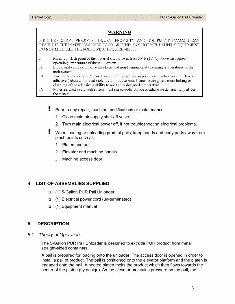
Prior to any repair, machine modifications or maintenance
1. Close main air supply shut-off valve.
2. Turn main electrical power off, if not troubleshooting electrical problems.
When loading or unloading product pails, keep hands and body parts away from pinch points such as:
1. Platen and pail.
2. Elevator and machine panels.
3. Machine access door.
4 LIST OF ASSEMBLIES SUPPLIED
(1) 5-Gallon PUR Pail Unloader
(1) Electrical power cord (un-terminated)
(1) Equipment manual
5 DESCRIPTION
5.1 Theory of Operation
The 5-Gallon PUR Pail Unloader is designed to extrude PUR product from metal straight-sided containers.
A pail is prepared for loading onto the unloader. The access door is opened in order to install a pail of product. The pail is positioned onto the elevator platform and the platen is engaged onto the pail. A heated platen melts the product which then flows towards the center of the platen (by design). As the elevator maintains pressure on the pail, the
3
Henkel Corp. PUR 5-Gallon Pail Unloader
liquefied product is channeled towards the gear pump around the bottom center of the platen. On the control panel, a temperature range is selected that is within the products temperature use. Once the application temperature is reached, the equipment is ready to dispense product. When the applicator trigger is actuated, the gear pump turns on and forces the product down the heated hose and towards the dispense applicator.
5.2 Main Components
5.2.1 Control Panel
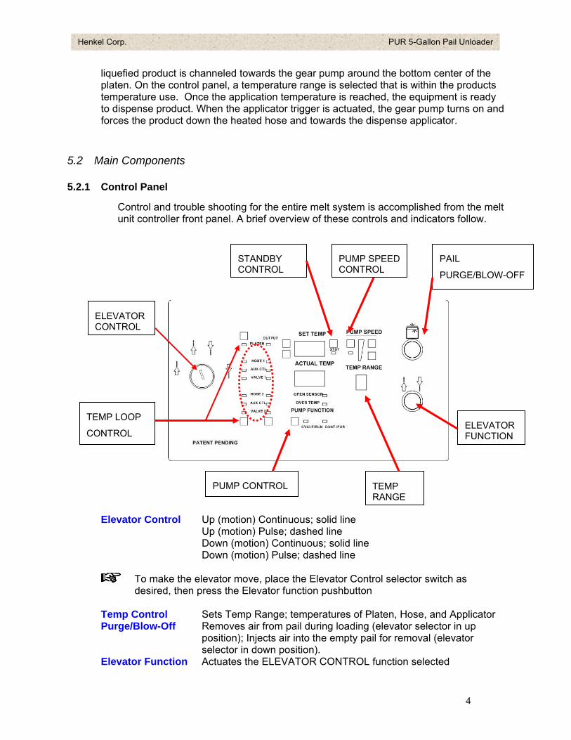
Control and trouble shooting for the entire melt system is accomplished from the melt unit controller front panel. A brief overview of these controls and indicators follow.
Elevator Control Up (motion) Continuous; solid line Up (motion) Pulse; dashed line Down (motion) Continuous; solid line Down (motion) Pulse; dashed line
To make the elevator move, place the Elevator Control selector switch as desired, then press the Elevator function pushbutton
Temp Control Sets Temp Range; temperatures of Platen, Hose, and Applicator Purge/Blow-Off Removes air from pail during loading (elevator selector in up
position); Injects air into the empty pail for removal (elevator selector in down position).
Elevator Function Actuates the ELEVATOR CONTROL function selected
ELEVATOR CONTROL
PAIL
PURGE/BLOW-OFF
PUMP CONTROL
STANDBY CONTROL
PUMP SPEED CONTROL
TEMP RANGE
ELEVATOR FUNCTION
TEMP LOOP
CONTROL
4
Henkel Corp. PUR 5-Gallon Pail Unloader
Pump Speed In increments of 2% (each bar represents 10%) Temp Range Current range selected Pump Control Turns On/Off the Pump Standby Control Places process temperatures set points 40% below nominal for a
preset (programmable) time
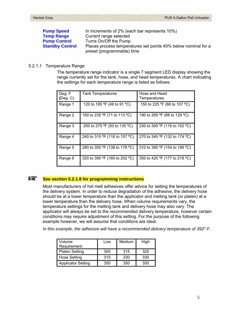
5.2.1.1 Temperature Range The temperature range indicator is a single 7 segment LED display showing the range currently set for the tank, hose, and head temperatures. A chart indicating the settings for each temperature range is listed as follows:
Deg. F (Deg. C)
Tank Temperatures Hose and Head Temperatures
Range 1 120 to 195 ºF (49 to 91 ºC) 150 to 225 ºF (66 to 107 ºC)
Range 2 160 to 235 ºF (71 to 113 ºC) 190 to 265 ºF (88 to 129 ºC)
Range 3 200 to 275 ºF (93 to 135 ºC) 230 to 305 ºF (116 to 152 ºC)
Range 4 240 to 315 ºF (116 to 157 ºC) 270 to 345 ºF (132 to 174 ºC)
Range 5 280 to 355 ºF (138 to 179 ºC) 310 to 385 ºF (154 to 196 ºC)
Range 6 320 to 395 ºF (160 to 202 ºC) 350 to 425 ºF (177 to 218 ºC)
See section 5.2.1.8 for programming instructions
Most manufacturers of hot melt adhesives offer advice for setting the temperatures of the delivery system. In order to reduce degradation of the adhesive, the delivery hose should be at a lower temperature than the applicator and melting tank (or platen) at a lower temperature than the delivery hose. When volume requirements vary, the temperature settings for the melting tank and delivery hose may also vary. The applicator will always be set to the recommended delivery temperature, however certain conditions may require adjustment of this setting. For the purpose of the following example however, we will assume that conditions are ideal.
In this example, the adhesive will have a recommended delivery temperature of 350° F.
Volume Requirement:
Low Medium High
Platen Setting 300 315 325 Hose Setting 315 330 330 Applicator Setting 350 350 350
5
Henkel Corp. PUR 5-Gallon Pail Unloader
5.2.1.2 Zone Heating Indicator
The series of Loop Output indicators refer to the platen, hose, and head. The LED’s will flash amber while warming up. Once the desired temperature has been reached, each LED Loop Indicator output will turn to a green color. Note that all three LED’s should be a flashing green color before dispensing adhesive.
5.2.1.3 Melt Unit Ready Lamps
When the Melt Unit is ready to operate, all three LED indicators as observed on the Loop Output Indicator row of LED’s will flash green. Note that the pump will not operate until the Pump Platen is at temperature. The pump platen is at temperature when the associated LED is flashing GREEN.
The pump WILL operate even if the HOSE or HEAD is NOT at temperature. It is therefore recommended that adhesive only be dispensed after all of the LED’s have changed from a flashing AMBER color to a flashing GREEN color.
5.2.1.4 Temperature Setting to Fahrenheit or Celsius
o Use the Loop Select Up/Down button to select Platen. The LED to the left of the device should show green.
o Press the Loop Select button four times. The Range indicator will start to blink.
o Pressing the Loop Select button will toggle the display from degrees C and F and vice-versa.
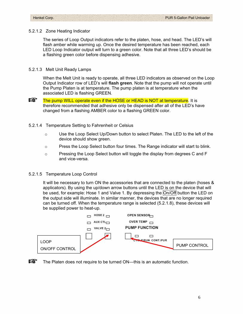
5.2.1.5 Temperature Loop Control
It will be necessary to turn ON the accessories that are connected to the platen (hoses & applicators). By using the up/down arrow buttons until the LED is on the device that will be used, for example: Hose 1 and Valve 1. By depressing the On/Off button the LED on the output side will illuminate. In similar manner, the devices that are no longer required can be turned off. When the temperature range is selected (5.2.1.8), these devices will be supplied power to heat-up.
LOOP
ON/OFF CONTROL PUMP CONTROL
The Platen does not require to be turned ON—this is an automatic function.
6
Henkel Corp. PUR 5-Gallon Pail Unloader
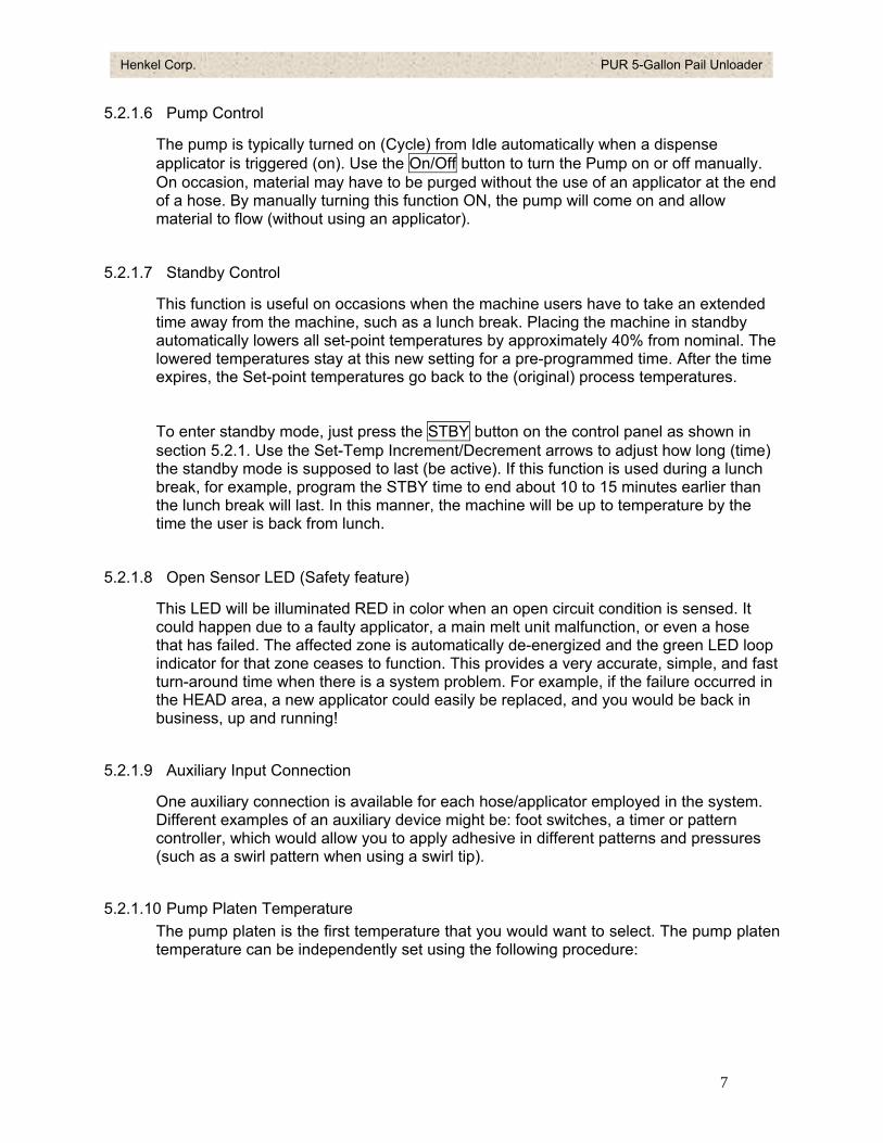
5.2.1.6 Pump Control
The pump is typically turned on (Cycle) from Idle automatically when a dispense applicator is triggered (on). Use the On/Off button to turn the Pump on or off manually. On occasion, material may have to be purged without the use of an applicator at the end of a hose. By manually turning this function ON, the pump will come on and allow material to flow (without using an applicator).
5.2.1.7 Standby Control
This function is useful on occasions when the machine users have to take an extended time away from the machine, such as a lunch break. Placing the machine in standby automatically lowers all set-point temperatures by approximately 40% from nominal. The lowered temperatures stay at this new setting for a pre-programmed time. After the time expires, the Set-point temperatures go back to the (original) process temperatures.
To enter standby mode, just press the STBY button on the control panel as shown in section 5.2.1. Use the Set-Temp Increment/Decrement arrows to adjust how long (time) the standby mode is supposed to last (be active). If this function is used during a lunch break, for example, program the STBY time to end about 10 to 15 minutes earlier than the lunch break will last. In this manner, the machine will be up to temperature by the time the user is back from lunch.
5.2.1.8 Open Sensor LED (Safety feature)
This LED will be illuminated RED in color when an open circuit condition is sensed. It could happen due to a faulty applicator, a main melt unit malfunction, or even a hose that has failed. The affected zone is automatically de-energized and the green LED loop indicator for that zone ceases to function. This provides a very accurate, simple, and fast turn-around time when there is a system problem. For example, if the failure occurred in the HEAD area, a new applicator could easily be replaced, and you would be back in business, up and running!
5.2.1.9 Auxiliary Input Connection
One auxiliary connection is available for each hose/applicator employed in the system. Different examples of an auxiliary device might be: foot switches, a timer or pattern controller, which would allow you to apply adhesive in different patterns and pressures (such as a swirl pattern when using a swirl tip).
5.2.1.10 Pump Platen Temperature The pump platen is the first temperature that you would want to select. The pump platen temperature can be independently set using the following procedure:
7
Henkel Corp. PUR 5-Gallon Pail Unloader
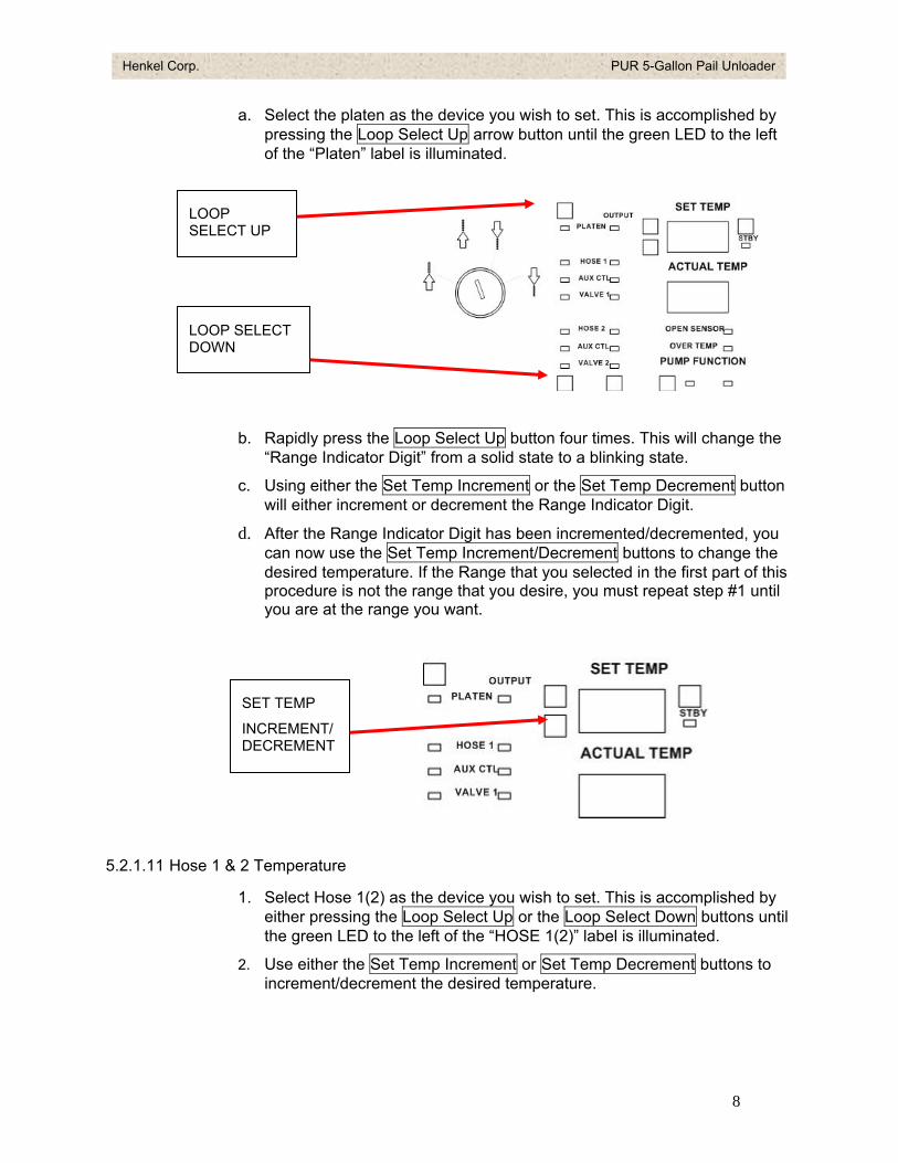
a. Select the platen as the device you wish to set. This is accomplished by pressing the Loop Select Up arrow button until the green LED to the left of the “Platen” label is illuminated.
LOOP SELECT UP
LOOP SELECT DOWN
b. Rapidly press the Loop Select Up button four times. This will change the “Range Indicator Digit” from a solid state to a blinking state.
c. Using either the Set Temp Increment or the Set Temp Decrement button will either increment or decrement the Range Indicator Digit.
d. After the Range Indicator Digit has been incremented/decremented, you can now use the Set Temp Increment/Decrement buttons to change the desired temperature. If the Range that you selected in the first part of this procedure is not the range that you desire, you must repeat step #1 until you are at the range you want.
SET TEMP
INCREMENT/DECREMENT
5.2.1.11 Hose 1 & 2 Temperature
1. Select Hose 1(2) as the device you wish to set. This is accomplished by either pressing the Loop Select Up or the Loop Select Down buttons until the green LED to the left of the “HOSE 1(2)” label is illuminated.
2. Use either the Set Temp Increment or Set Temp Decrement buttons to increment/decrement the desired temperature.
8
Henkel Corp. PUR 5-Gallon Pail Unloader
5.2.1.12 Head 1 & 2 Temperature
1. Select Head 1(2) as the device you wish to set. This is accomplished by either pressing the Loop Select Up or the Loop Select Down buttons until the green LED to the left of the “HEAD 1(2)” label is illuminated.
2. Use either the Set Temp Increment or Set Temp Decrement buttons to increment/decrement the desired temperature.
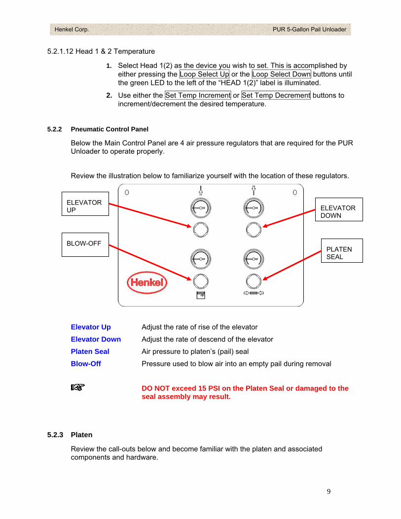
5.2.2 Pneumatic Control Panel
Below the Main Control Panel are 4 air pressure regulators that are required for the PUR Unloader to operate properly.
Review the illustration below to familiarize yourself with the location of these regulators.
Elevator Up Adjust the rate of rise of the elevator
Elevator Down Adjust the rate of descend of the elevator
Platen Seal Air pressure to platen’s (pail) seal
Blow-Off Pressure used to blow air into an empty pail during removal
DO NOT exceed 15 PSI on the Platen Seal or damaged to the seal assembly may result.
ELEVATOR UP ELEVATOR
DOWN
PLATEN SEAL
BLOW-OFF
5.2.3 Platen
Review the call-outs below and become familiar with the platen and associated components and hardware.
9
Henkel Corp. PUR 5-Gallon Pail Unloader
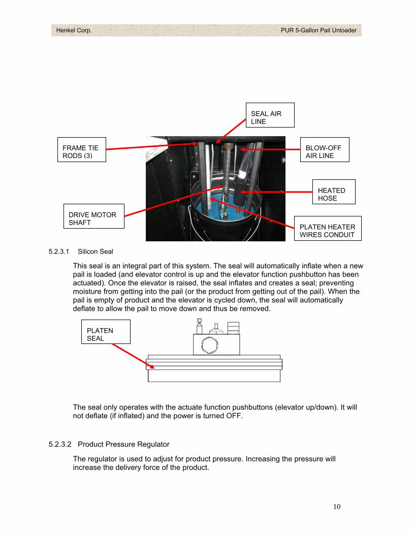
5.2.3.1 Silicon Seal
This seal is an integral part of this system. The seal will automatically inflate when a new pail is loaded (and elevator control is up and the elevator function pushbutton has been actuated). Once the elevator is raised, the seal inflates and creates a seal; preventing moisture from getting into the pail (or the product from getting out of the pail). When the pail is empty of product and the elevator is cycled down, the seal will automatically deflate to allow the pail to move down and thus be removed.
The seal only operates with the actuate function pushbuttons (elevator up/down). It will not deflate (if inflated) and the power is turned OFF.
PLATEN SEAL
FRAME TIE RODS (3)
HEATED HOSE
PLATEN HEATER WIRES CONDUIT
SEAL AIR LINE
BLOW-OFF AIR LINE
DRIVE MOTOR SHAFT
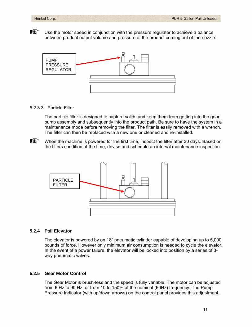
5.2.3.2 Product Pressure Regulator
The regulator is used to adjust for product pressure. Increasing the pressure will increase the delivery force of the product.
10
Henkel Corp. PUR 5-Gallon Pail Unloader
Use the motor speed in conjunction with the pressure regulator to achieve a balance between product output volume and pressure of the product coming out of the nozzle.
PUMP PRESSURE REGULATOR
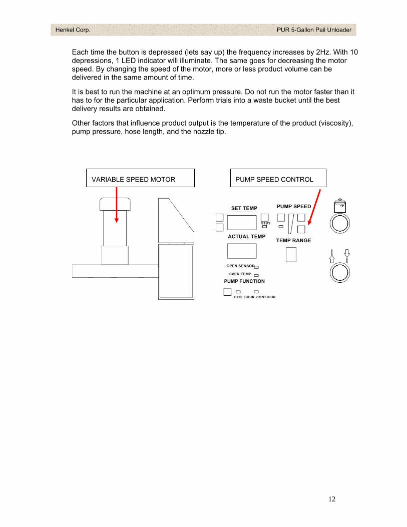
5.2.3.3 Particle Filter
The particle filter is designed to capture solids and keep them from getting into the gear pump assembly and subsequently into the product path. Be sure to have the system in a maintenance mode before removing the filter. The filter is easily removed with a wrench. The filter can then be replaced with a new one or cleaned and re-installed.
When the machine is powered for the first time, inspect the filter after 30 days. Based on the filters condition at the time, devise and schedule an interval maintenance inspection.
PARTICLE FILTER
5.2.4 Pail Elevator
The elevator is powered by an 18” pneumatic cylinder capable of developing up to 5,000 pounds of force. However only minimum air consumption is needed to cycle the elevator. In the event of a power failure, the elevator will be locked into position by a series of 3-way pneumatic valves.
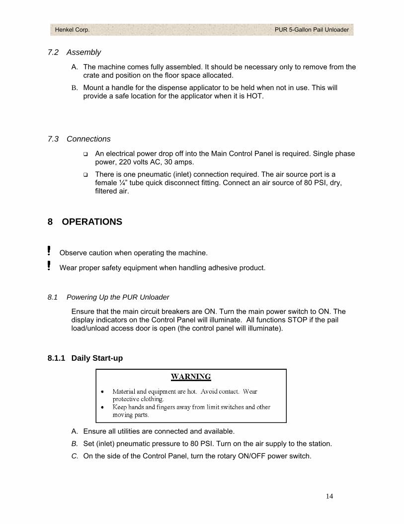
5.2.5 Gear Motor Control
The Gear Motor is brush-less and the speed is fully variable. The motor can be adjusted from 6 Hz to 90 Hz; or from 10 to 150% of the nominal (60Hz) frequency. The Pump Pressure Indicator (with up/down arrows) on the control panel provides this adjustment.
11
Henkel Corp. PUR 5-Gallon Pail Unloader
Each time the button is depressed (lets say up) the frequency increases by 2Hz. With 10 depressions, 1 LED indicator will illuminate. The same goes for decreasing the motor speed. By changing the speed of the motor, more or less product volume can be delivered in the same amount of time.
It is best to run the machine at an optimum pressure. Do not run the motor faster than it has to for the particular application. Perform trials into a waste bucket until the best delivery results are obtained.
Other factors that influence product output is the temperature of the product (viscosity), pump pressure, hose length, and the nozzle tip.
VARIABLE SPEED MOTOR PUMP SPEED CONTROL
12
Henkel Corp. PUR 5-Gallon Pail Unloader
6 TECHNICAL DATA
6.1 Specifications Data
6.1.1 Components
Platen 2300 Watts/with baked on Teflon coating, silicon inflatable seal
Gear Motor ½ hP, 10 to 150% frequency variable
Pump Flow rate 197 lb/hr
6.1.2 Weight
375 lbs.
6.1.3 Dimensions
30W x 22D x 52 ¼H
6.2 Energy Requirements
6.2.1 Electrical
Supply Voltage 220 VAC, ∅1 Phase
Amperage 30 Amp maximum
6.2.2 Pneumatic
Air Supply / Pneumatic 65 – 90 PSI
Quality Filtered 1 μm, oil free, non-condensing
6.2.3 Connections
Inlet Pneumatic 1/4 tube quick disconnect
Electrical single-phase power wires
7 INSTALLATION
7.1 Floor Space Requirements
Allow for machine size plus hose length. In addition, consider overhead space in the event the process may be more favorable to a hose hanging over the work area rather than having the hose lying on the floor.
13
Henkel Corp. PUR 5-Gallon Pail Unloader
7.2 Assembly
A. The machine comes fully assembled. It should be necessary only to remove from the crate and position on the floor space allocated.
B. Mount a handle for the dispense applicator to be held when not in use. This will provide a safe location for the applicator when it is HOT.
7.3 Connections
An electrical power drop off into the Main Control Panel is required. Single phase power, 220 volts AC, 30 amps.
There is one pneumatic (inlet) connection required. The air source port is a female ¼” tube quick disconnect fitting. Connect an air source of 80 PSI, dry, filtered air.
8 OPERATIONS
Observe caution when operating the machine.
Wear proper safety equipment when handling adhesive product.
8.1 Powering Up the PUR Unloader
Ensure that the main circuit breakers are ON. Turn the main power switch to ON. The display indicators on the Control Panel will illuminate. All functions STOP if the pail load/unload access door is open (the control panel will illuminate).
8.1.1 Daily Start-up
A. Ensure all utilities are connected and available.
B. Set (inlet) pneumatic pressure to 80 PSI. Turn on the air supply to the station.
C. On the side of the Control Panel, turn the rotary ON/OFF power switch.
14
Henkel Corp. PUR 5-Gallon Pail Unloader
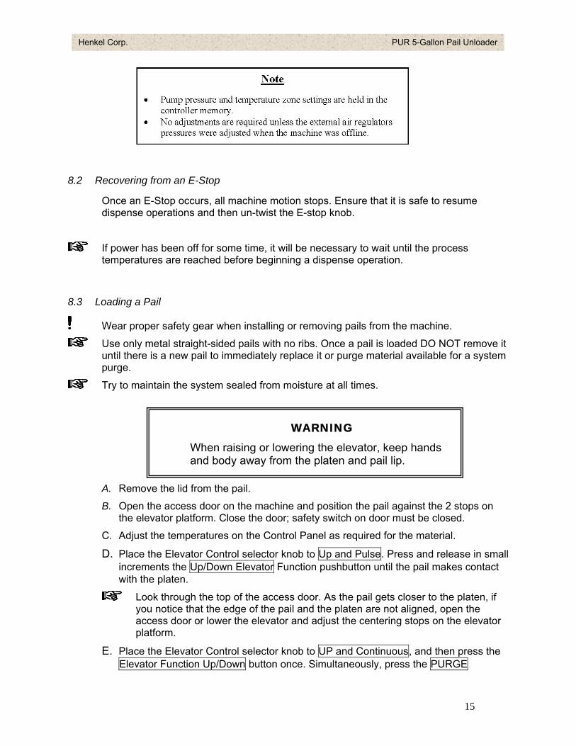
8.2 Recovering from an E-Stop
Once an E-Stop occurs, all machine motion stops. Ensure that it is safe to resume dispense operations and then un-twist the E-stop knob.
If power has been off for some time, it will be necessary to wait until the process temperatures are reached before beginning a dispense operation.
8.3 Loading a Pail
Wear proper safety gear when installing or removing pails from the machine. Use only metal straight-sided pails with no ribs. Once a pail is loaded DO NOT remove it
until there is a new pail to immediately replace it or purge material available for a system purge.
Try to maintain the system sealed from moisture at all times.
A. Remove the lid from the pail.
B. Open the access door on the machine and position the pail against the 2 stops on the elevator platform. Close the door; safety switch on door must be closed.
C. Adjust the temperatures on the Control Panel as required for the material.
D. Place the Elevator Control selector knob to Up and Pulse. Press and release in small increments the Up/Down Elevator Function pushbutton until the pail makes contact with the platen. Look through the top of the access door. As the pail gets closer to the platen, if
you notice that the edge of the pail and the platen are not aligned, open the access door or lower the elevator and adjust the centering stops on the elevator platform.
E. Place the Elevator Control selector knob to UP and Continuous, and then press the Elevator Function Up/Down button once. Simultaneously, press the PURGE
WARNING When raising or lowering the elevator, keep hands and body away from the platen and pail lip.
15
Henkel Corp. PUR 5-Gallon Pail Unloader
pushbutton to evacuate air from the pail as the elevator moves up. The elevator will ascend continuously and stop ascending once it comes into contact with the product in the pail. The platen seal will then inflate to seal the pail.
F. Wait until the temperatures are reached for all dispense components before beginning a dispense.
G. Adjust the pressure regulator and Gear motor speed if required.
8.4 Purging
Purging is required (typically) when a new pail is loaded. Purging removes any air that may have become trapped in the product path.
It is most important that all air is removed from the material or it may dispense irregularities and cause internal product curing.
The Purge function will only work when the elevator position selector is in the UP position.
A. During the Pail Loading procedure press the Purge/Blow-Off pushbutton on the top right corner of the control panel. This will actuate a valve and allow air to be released from the top of the pail as it nears the product in the pail.
B. Most of the air from loading the pail should be removed during pail loading and using the Purge pushbutton. If the previous pail was emptied and air bursts were observed at the applicator then: hold the dispense applicator over an empty pail (to capture waste).
C. Use the trigger on the applicator until a continuous stream of product is coming out without any burping or voids. This will remove the remaining air from the product path.
8.5 Removing an Empty Pail
Wear proper safety gear when installing or removing pails from the machine.
DO NOT remove a pail until there is a new pail readily available for loading. DO NOT open the pail access door until the elevator has come completely down.
A. Place the Elevator Control selector knob to the Pulse Down position.
B. Press and pulse the Elevator Up/Down pushbutton while pulsing the Blow-Off
pushbutton until the pail is lowered completely and is not in contact with the platen. The platen seal will deflate automatically.
C. If the pail does not lower when the elevator goes down
16
Henkel Corp. PUR 5-Gallon Pail Unloader
a. Ensure that the elevator is not too far from the bottom of the pail. Raise the elevator again if required and keep the pail within 2 to 3 inches from the elevator platform (in the event the pail suddenly drops, it will not be a violent fall).
b. Slowly increase the pressure to the Blow-OFF valve; this will blow air into the pail to separate the pail from the platen.
c. If necessary, with the elevator down, try to tilt slightly and rotate the pail to break the capillary seal with the platen.
8.6 Dispensing
8.6.1 Hand Held Applicator
A. Most applications will use a manual applicator. This device has a pump start switch opposite the trigger switch, which needs to be actuated for dispensing.
B. Press and hold the applicator’s trigger switch for dispensing to take place. Release the trigger to stop the adhesive flow.
When starting the machine for the first time each day, it is a good idea to dispense into a waste cup to check that the dispense setup (volume/pressure) is what is desired. Make adjustments if necessary—see sections 5.2.2.2 and 5.2.4
8.6.2 Automatic Valve
A. These valve types are fixed mounted valves for automatic dispensing. The valves
are available with electrical control and can be triggered with a footswitch, or can be integrated to a customer control system for remote triggering.
B. A pneumatic version of the automatic valve is also available for applications that
require fast cycle times; yet, typically have lower viscosities.
8.7 Shutting the System Down
The nature of the PUR material is such that it necessitates that the system (material path) be kept seal at all times. Whether overnight, weekend or extended shutdown, it is best to leave the system be as it is. The machine should power up as usual with no expected dispense problems so long as the system has remained sealed.
The one area that could experience a problem (most likely due to clogging) is the dispense nozzle. Harden material at the nozzle tip can be removed with a small pick or small drill bit.
Care should be observed not to enlarge the nozzle hole size when clearing the clog.
17
Henkel Corp. PUR 5-Gallon Pail Unloader
In event that the machine does not dispense after a start-up, see the Trouble-shooting section of this manual or refer to section 9.3.
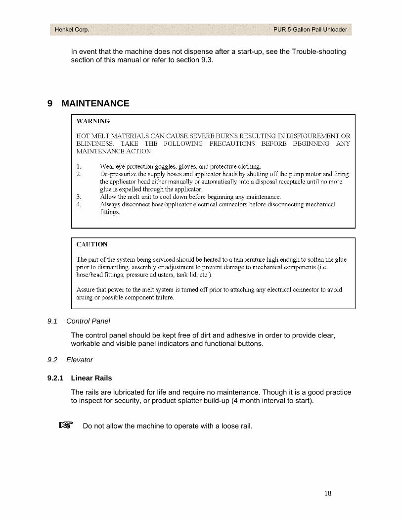
9 MAINTENANCE
9.1 Control Panel
The control panel should be kept free of dirt and adhesive in order to provide clear, workable and visible panel indicators and functional buttons.
9.2 Elevator
9.2.1 Linear Rails
The rails are lubricated for life and require no maintenance. Though it is a good practice to inspect for security, or product splatter build-up (4 month interval to start).
Do not allow the machine to operate with a loose rail.
18
Henkel Corp. PUR 5-Gallon Pail Unloader
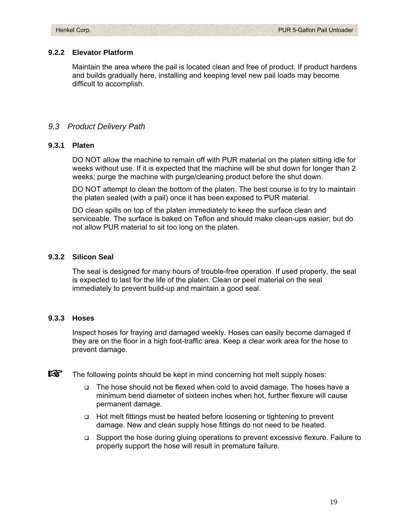
9.2.2 Elevator Platform
Maintain the area where the pail is located clean and free of product. If product hardens and builds gradually here, installing and keeping level new pail loads may become difficult to accomplish.
9.3 Product Delivery Path
9.3.1 Platen
DO NOT allow the machine to remain off with PUR material on the platen sitting idle for weeks without use. If it is expected that the machine will be shut down for longer than 2 weeks; purge the machine with purge/cleaning product before the shut down.
DO NOT attempt to clean the bottom of the platen. The best course is to try to maintain the platen sealed (with a pail) once it has been exposed to PUR material.
DO clean spills on top of the platen immediately to keep the surface clean and serviceable. The surface is baked on Teflon and should make clean-ups easier; but do not allow PUR material to sit too long on the platen.
9.3.2 Silicon Seal
The seal is designed for many hours of trouble-free operation. If used properly, the seal is expected to last for the life of the platen. Clean or peel material on the seal immediately to prevent build-up and maintain a good seal.
9.3.3 Hoses
Inspect hoses for fraying and damaged weekly. Hoses can easily become damaged if they are on the floor in a high foot-traffic area. Keep a clear work area for the hose to prevent damage.
The following points should be kept in mind concerning hot melt supply hoses:
The hose should not be flexed when cold to avoid damage. The hoses have a minimum bend diameter of sixteen inches when hot, further flexure will cause permanent damage.
Hot melt fittings must be heated before loosening or tightening to prevent damage. New and clean supply hose fittings do not need to be heated.
Support the hose during gluing operations to prevent excessive flexure. Failure to properly support the hose will result in premature failure.
19
Henkel Corp. PUR 5-Gallon Pail Unloader
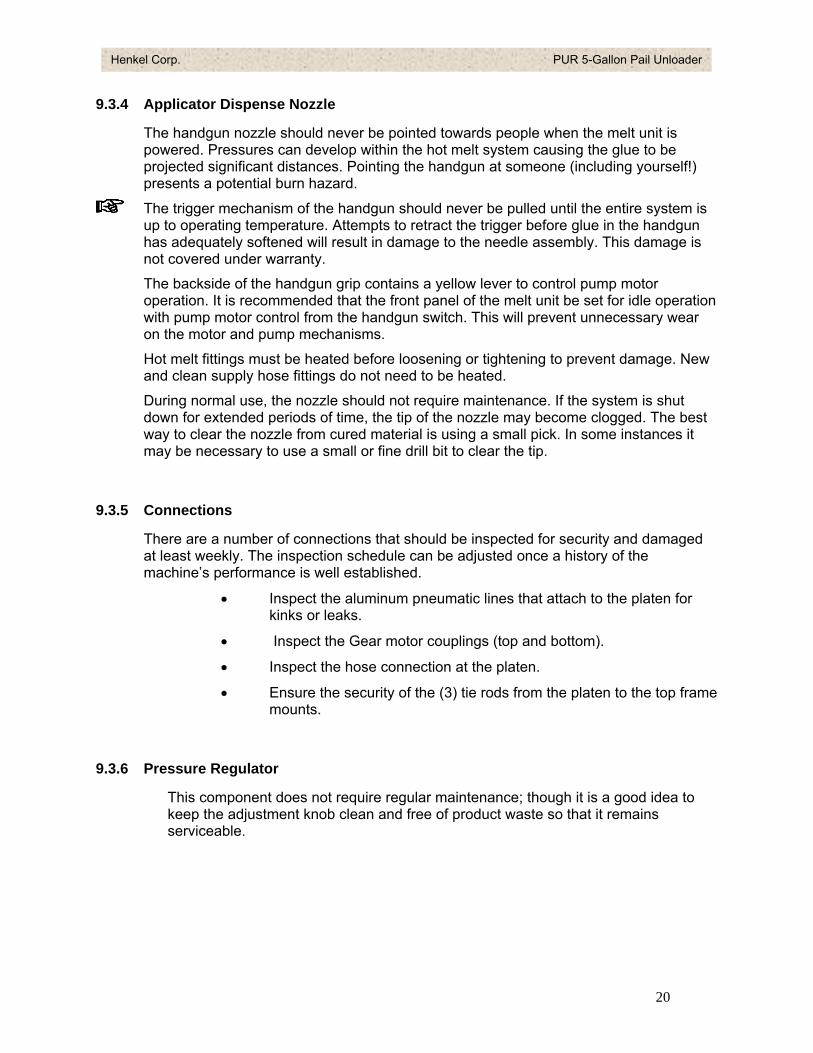
9.3.4 Applicator Dispense Nozzle
The handgun nozzle should never be pointed towards people when the melt unit is powered. Pressures can develop within the hot melt system causing the glue to be projected significant distances. Pointing the handgun at someone (including yourself!) presents a potential burn hazard.
The trigger mechanism of the handgun should never be pulled until the entire system is up to operating temperature. Attempts to retract the trigger before glue in the handgun has adequately softened will result in damage to the needle assembly. This damage is not covered under warranty.
The backside of the handgun grip contains a yellow lever to control pump motor operation. It is recommended that the front panel of the melt unit be set for idle operation with pump motor control from the handgun switch. This will prevent unnecessary wear on the motor and pump mechanisms.
Hot melt fittings must be heated before loosening or tightening to prevent damage. New and clean supply hose fittings do not need to be heated.
During normal use, the nozzle should not require maintenance. If the system is shut down for extended periods of time, the tip of the nozzle may become clogged. The best way to clear the nozzle from cured material is using a small pick. In some instances it may be necessary to use a small or fine drill bit to clear the tip.
9.3.5 Connections
There are a number of connections that should be inspected for security and damaged at least weekly. The inspection schedule can be adjusted once a history of the machine’s performance is well established.
• Inspect the aluminum pneumatic lines that attach to the platen for kinks or leaks.
• Inspect the Gear motor couplings (top and bottom).
• Inspect the hose connection at the platen.
• Ensure the security of the (3) tie rods from the platen to the top frame mounts.
9.3.6 Pressure Regulator
This component does not require regular maintenance; though it is a good idea to keep the adjustment knob clean and free of product waste so that it remains serviceable.
20
Henkel Corp. PUR 5-Gallon Pail Unloader
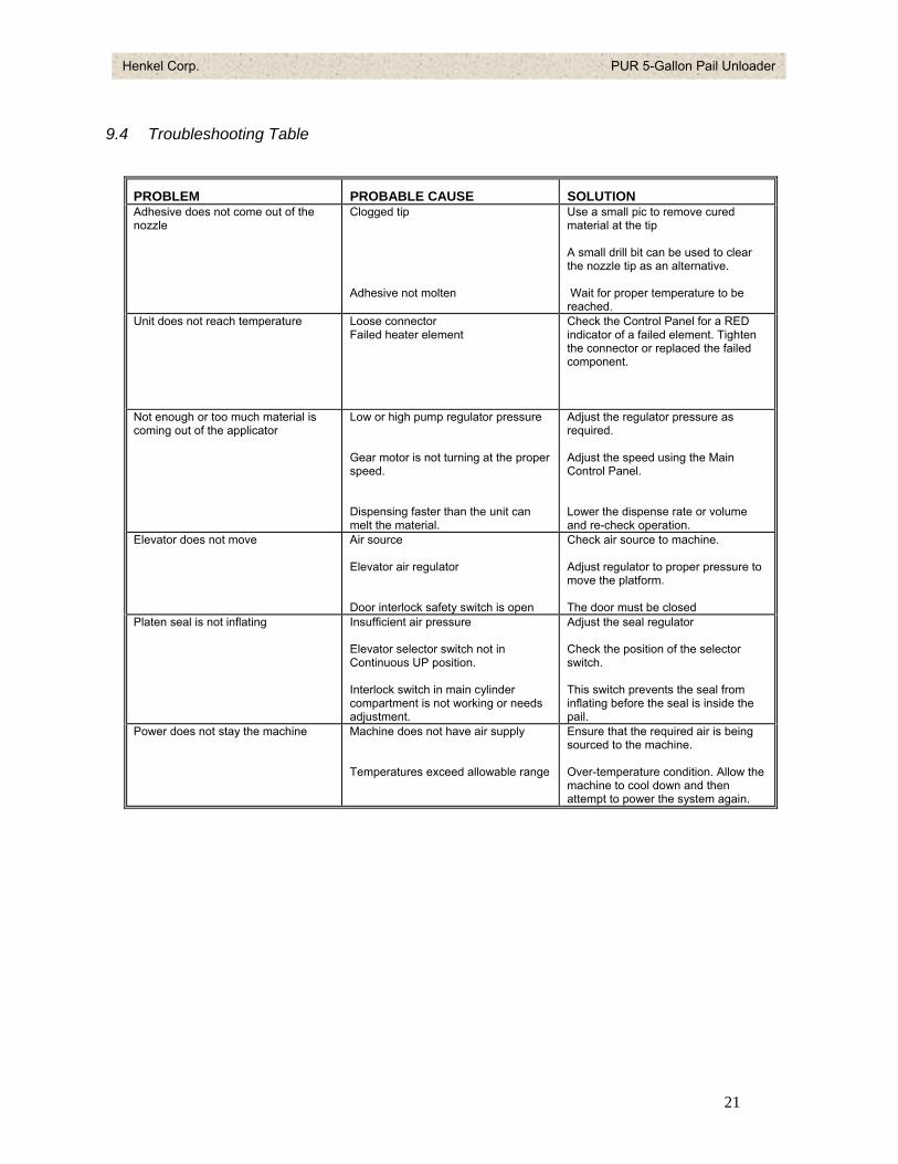
9.4 Troubleshooting Table
PROBLEM PROBABLE CAUSE SOLUTION Adhesive does not come out of the nozzle
Clogged tip Adhesive not molten
Use a small pic to remove cured material at the tip A small drill bit can be used to clear the nozzle tip as an alternative. Wait for proper temperature to be reached.
Unit does not reach temperature Loose connector Failed heater element
Check the Control Panel for a RED indicator of a failed element. Tighten the connector or replaced the failed component.
Not enough or too much material is coming out of the applicator
Low or high pump regulator pressure Gear motor is not turning at the proper speed. Dispensing faster than the unit can melt the material.
Adjust the regulator pressure as required. Adjust the speed using the Main Control Panel. Lower the dispense rate or volume and re-check operation.
Elevator does not move Air source Elevator air regulator Door interlock safety switch is open
Check air source to machine. Adjust regulator to proper pressure to move the platform. The door must be closed
Platen seal is not inflating Insufficient air pressure Elevator selector switch not in Continuous UP position. Interlock switch in main cylinder compartment is not working or needs adjustment.
Adjust the seal regulator Check the position of the selector switch. This switch prevents the seal from inflating before the seal is inside the pail.
Power does not stay the machine Machine does not have air supply Temperatures exceed allowable range
Ensure that the required air is being sourced to the machine. Over-temperature condition. Allow the machine to cool down and then attempt to power the system again.
21
Henkel Corp. PUR 5-Gallon Pail Unloader
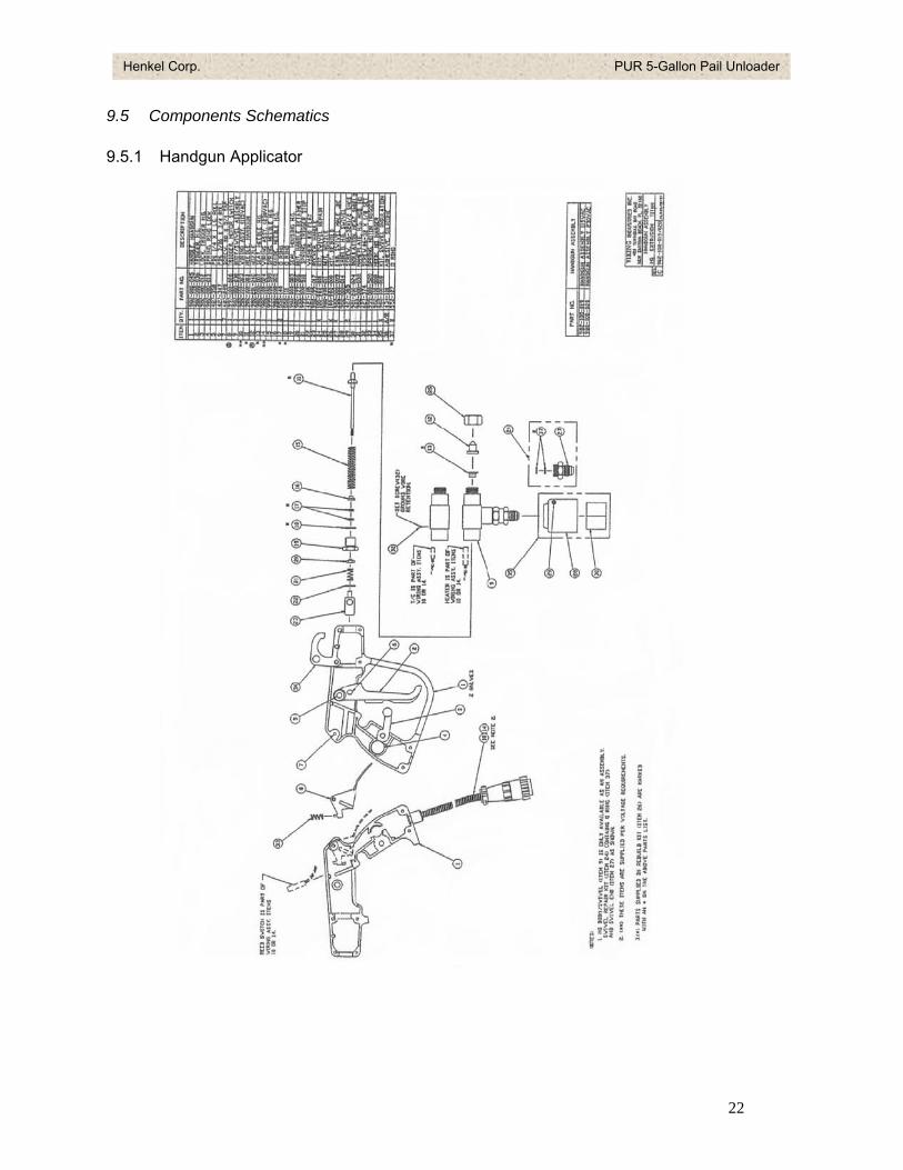
9.5 Components Schematics
9.5.1 Handgun Applicator
22
Henkel Corp. PUR 5-Gallon Pail Unloader
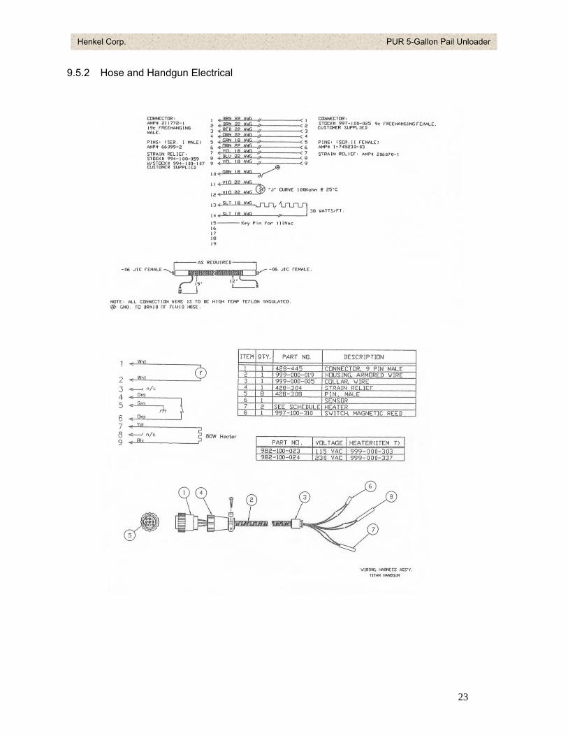
9.5.2 Hose and Handgun Electrical
23
Henkel Corp. PUR 5-Gallon Pail Unloader
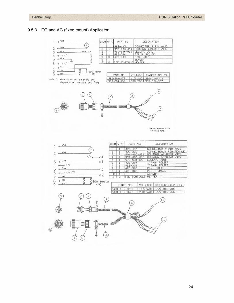
9.5.3 EG and AG (fixed mount) Applicator
24

Henkel Corp. PUR 5-Gallon Pail Unloader
10 REPLACEMENT PARTS Visit www.loctite.com and look in Hot Melt equipment pages, or contact your local Henkel sales representative to request a quote for specific Loctite components.
25