Pumps Overview
106
Baljit S Bagga Pumps an Overview PUMPS an Overview PUMPS an Overview • Types, Applications & Hydraulic Calculations • Rotodynamic Pumps Single Stage Centrifugal Pumps Multistage Centrifugal Pumps • Positive Displacement Pumps Reciprocating Pumps Rotary Pumps
description
Pump Overview
Transcript of Pumps Overview

Baljit S BaggaPumps an Overview
PUMPS an OverviewPUMPS an Overview• Types, Applications & Hydraulic Calculations
• Rotodynamic Pumps Single Stage Centrifugal Pumps Multistage Centrifugal Pumps
• Positive Displacement Pumps Reciprocating Pumps Rotary Pumps

Baljit S BaggaPumps an Overview
PUMPS an OverviewPUMPS an Overview
• What is a Pump?• How many different types of Pumps?• Application of Pumps in Industry• Pump Terminology & Definitions• Pumps in Hydrocarbon, Oil & Gas Industry • Difference between Pump and compressor• What is the closest & dearest Pump to you?• Pump Technology Advancements (3 phase pumping)• Sub-sea Multiphase pumping

Baljit S BaggaPumps an Overview
MACHINERY APPLICATIONMACHINERY APPLICATION
An overview of the Machinery used in Exploration and Production Activities
• General concepts
• Fluid machinery fundamentals
• Pumps
• Compressors
• Drivers

Baljit S BaggaPumps an Overview
DRIVER
TR
AN
SM
ISS
ION
DRIVEN UNIT
GAS TURBINE
ELECTRIC MOTOR
DIESEL ENGINE
GAS ENGINE
Steam Turbine, Hydraulic turbine
Compressed Air
GENERATOR
PUMP
COMPRESSOR
BASEPLATEENCLOSURELUBRICATIONCOOLINGVENTILATIONAIR INTAKE ETC
GEARBOXCLUTCHFLUID COUPLINGFLEXIBLE COUPLINGS
MACHINERY PACKAGE

Baljit S BaggaPumps an Overview
MAIN CLASSES OF FLUID MACHINEMAIN CLASSES OF FLUID MACHINE
Fluid machines fall into two main classes: Turbomachines:
Centrifugal Axial
Displacement Machines: Reciprocating Rotary

Baljit S BaggaPumps an Overview
Turbomachinery Working PrincipleTurbomachinery Working Principle
• Rotor adds kinetic energy to fluid
• Kinetic energy converted to pressure energy
Bernouilli’s equation:p + ½ V2 = constantp = pressure = densityV = velocity

Baljit S BaggaPumps an Overview
Turbomachine RotorsTurbomachine Rotors
Centrifugal Rotor Axial Rotor

Baljit S BaggaPumps an Overview
TURBOMACHINE STATORS: DIFFUSERSTURBOMACHINE STATORS: DIFFUSERS
VANED DIFFUSERSCROLL DIFFUSER

Baljit S BaggaPumps an Overview
Turbomachine Performance CurveTurbomachine Performance Curve
Flow
Pres
sure
Increasing Speed, Diameter, Density

Baljit S BaggaPumps an Overview
Displacement Machines: Displacement Machines: ReciprocatingReciprocating
CRANKCROSSHEAD PISTON SUCTION VALVE
DISCHARGE VALVE

Baljit S BaggaPumps an Overview
Displacement Machines: RotaryDisplacement Machines: Rotary
THREE LOBE PUMP

Baljit S BaggaPumps an Overview
Displacement Machine: Performance Displacement Machine: Performance CurveCurve
FLOW
PR
ES
SU
RE

Baljit S BaggaPumps an Overview
System Resistance CurveSystem Resistance Curve
Machine
Reservoir
Pressure = Pr
Process resistance curve
Flow
Pre
ssu
re d
rop
Pr

Baljit S BaggaPumps an Overview
Machine and System: Operating Machine and System: Operating PointPoint
Flow
Pre
ssur
e

Baljit S BaggaPumps an Overview
Machines in Parallel and SeriesMachines in Parallel and Series
Machines in Series
Flow
Pre
ssur
e
Machines in Parallel
Flow
Pre
ssur
e

Baljit S BaggaPumps an Overview
PUMPS an OverviewPUMPS an Overview
• What is a Pump? – “A machine used for the purpose of transferring quantities of fluids (and /or gases) from one place to other” Pump generates head.
• Pump Types – Rotodynamic and Positive Displacement Centrifugal - Reciprocating Volute Piston Diffuser Plunger (API610 - 18 Types Diaphragm
classified as Rotary Pumps Overhung (OH1-6) Screw (single, twin screw) Between Bearings (BB1-5) Gear type Vertical Shafts (VS1-7) Vane type Lobe type
• Application of Pumps in Industry (more than 120 + applications, e.g. in steel, paper, brewery, water, transport, aviation, automobile, power plants industries)
• Pump Terminology & Definitions (Hydraulic Institute Publications, International codes & standards have 28000 + terms and 14000+ definitions)

Baljit S BaggaPumps an Overview
PUMPS an OverviewPUMPS an Overview
• Pumps in Hydrocarbon, Oil & Gas Industry• Pumps have a wide application in the industry• Pumps are employed at the very core of E&P business
- crude oil treating and transport
- water treating and injection
- condensate handling
• Pumps are also employed for ancillary and utility applications, e.g.
- chemical injection
- fuel transfer
- lube oil circulation
- Cooling medium circulation
- fire water, - drinking water
- domestic sewage
• Pumps employed for special applications, e.g. downhole ESP, PCP and beam pumps. (ESP- electro-submersible pump, PCP-progressive cavity pump)

Baljit S BaggaPumps an Overview
Pumps in Upstream OperationsPumps in Upstream Operations *

Baljit S BaggaPumps an Overview
ObjectivesObjectives
Brief overview of pump hydraulics and terminology
• Review selection of the two main types of pumps and their drivers:
Roto-dynamic (centrifugal pumps)
Positive displacement (reciprocating, rotary)
• Discuss Centrifugal pump relationship of
“head” and pump fluid’s “pressure increase”• Review cavitation that can damage a pump
• Match a pump curve to the “system” curve

Baljit S BaggaPumps an Overview
Simplified Pump hydraulic sketchSimplified Pump hydraulic sketch
FE
Pipe Fric lossSuction & Dis
Static Gain CV loss
Static Loss
Eqipment Loss
Strainer Loss
Flow Element
(FE) Loss
Valve Loss
Psuction
Low Liq Level
Pdestination
Rated = 200 gpm @ Head = 300 ft
T/L Elev
Pump C/L
Grade
Hi Liq Level

Baljit S BaggaPumps an Overview
Pump HardwarePump Hardware
Pump HardwarePump Hardware
Volute CasingVolute CasingDiffuserDiffuserSuction nozzleSuction nozzleDischarge NozzleDischarge NozzleImpellersImpellersVanesVanesShroudShroudWear ringsWear ringsBearingsBearingsStuffing boxStuffing boxShaft SealsShaft SealsCouplingCouplingDriverDriverBaseplateBaseplate

Baljit S BaggaPumps an Overview
Pressure profile inside pumpPressure profile inside pump
Pressure profileinside pump

Baljit S BaggaPumps an Overview
Bottom line - How Do I Select a Bottom line - How Do I Select a Pump?Pump?
• What are the Issues?– Flow– Required head– Upstream and downstream losses– NPSHA vs. NPSHR
– Installation (series or parallel)– Controls– Other issues?
• Pump selection guide – General Range
- Further details in later slides

Baljit S BaggaPumps an Overview
General Ranges of Application for Different Pump Types General Ranges of Application for Different Pump Types

Baljit S BaggaPumps an Overview
NPSHANPSHA

Baljit S BaggaPumps an Overview
TopicsTopics
• Pump Purpose• Pump Types and Major Components• Fundamentals of Pumps• Pump System Calculations• Pump Installations• Pump Selections• Summary• Class Problem

Baljit S BaggaPumps an Overview
Purpose of PumpsPurpose of Pumps
10 m
200 kPa 1000 kPa
200 m3/hr
500 m3/hr
Purpose

Baljit S BaggaPumps an Overview
TopicsTopics
• Pump Purpose
• Pump types and
Major Components of
Centrifugal and Reciprocating Pumps
• Fundamentals of Pumps• Pump System Calculations• Installation Issues and Surveillance• Pump Selections• Summary• Class Problem

Baljit S BaggaPumps an Overview
Centrifugal PumpsCentrifugal Pumps
Multi Stage Centrifugal PumpMulti Stage Centrifugal Pump
RasGas Sulfinol Circulation Pump
Pump Types

Baljit S BaggaPumps an Overview
Centrifugal PumpsCentrifugal Pumps
Eelectric motor driven Centrifugal pump.
Pump Types

Baljit S BaggaPumps an Overview
Centrifugal PumpsCentrifugal Pumps
Low pressure separator feeds deep well vertical turbine pump
Head above pump intake prevents cavitation
Vertical PumpVertical Pump
Pump Types

Baljit S BaggaPumps an Overview
Vertical Pump InstallationVertical Pump Installation
Right angle drive
Pump Types
Baljit S BaggaPumps an Overview
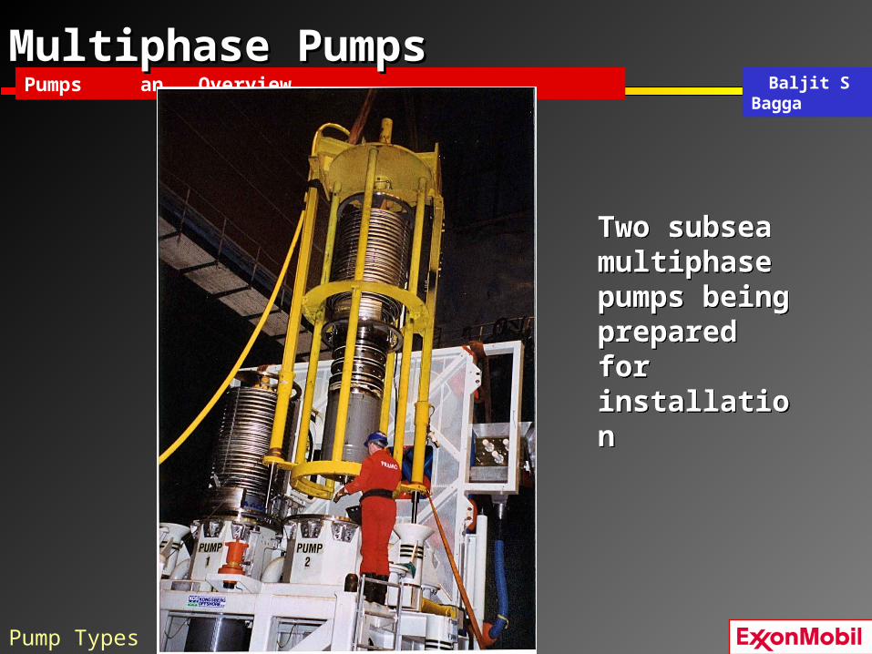
Multiphase PumpsMultiphase Pumps
Two subsea multiphase pumps being prepared for installation
Two subsea multiphase pumps being prepared for installation
Pump Types

Baljit S BaggaPumps an Overview
Centrifugal PumpsCentrifugal Pumps
Single Stage Centrifugal PumpSingle Stage Centrifugal Pump
Pump Components

Baljit S BaggaPumps an Overview
Basic Types of ImpellersBasic Types of Impellers
Pump Components

Baljit S BaggaPumps an Overview
Horizontal Single Stage Pump - Major Horizontal Single Stage Pump - Major ComponentsComponents
• Horizontal, single stage, overhung• Bearings support shaft (cantilevered)• Stuffing box holds seal(s) or packing
GPSA Fig 12-6a
Pump Components

Baljit S BaggaPumps an Overview
Horizontal Multi-Stage Pump - Major ComponentsHorizontal Multi-Stage Pump - Major Components
• Horizontal, multi-stage, opposed impellers (thrust balancing)
• Axially split case• Mechanical seals
GPSA Fig 12-6c
Pump Components

Baljit S BaggaPumps an Overview
Reciprocating PumpsReciprocating Pumps
ENERGY Pushing
Also called Plunger PumpsAlso called Plunger Pumps
Pump Components

Baljit S BaggaPumps an Overview
Reciprocating PumpsReciprocating Pumps
LaBarge TEGCirculation Pump
Pump Components

Baljit S BaggaPumps an Overview
TopicsTopics
• Pump Purpose• Pump types and Major Components
• Fundamentals of Pumps• Pump System Calculations• Driver Choices• Installation Issues and Surveillance• Pump Selections• Summary• Class Problem
Baljit S BaggaPumps an Overview
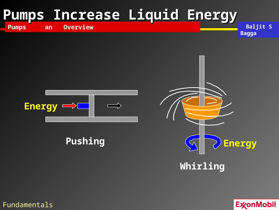
Pumps Increase Liquid EnergyPumps Increase Liquid Energy
Pushing
Whirling
Energy
Energy
Fundamentals

Baljit S BaggaPumps an Overview
Centrifugal PumpsCentrifugal Pumps
Pushing
Whirling
Energy
Energy
Fundamentals

Baljit S BaggaPumps an Overview
Head and PressureHead and Pressure
HEAD
Head is independent of diameter
The pressure at the bottom of each cylinder is the same
10 ft 4.3
Afor water SG = 1.0so PA = 4.3 psig
100 ft
B
43.
Pressure = h * SG * 0.43 Head = P * 2.31 / SG
PB = 43. psig
*
Fundamentals

Baljit S BaggaPumps an Overview
Head and PressureHead and Pressure
HEAD
Head is independent of diameter
The pressure at the bottom of each cylinder is the same
10 m 98
A100 m
B
980
for water SG = 1.0so PA = 98 kPa PB = 980 kPa
Pressure = h * SG * 9.81 Head = P / (SG * 9.81)
Fundamentals

Baljit S BaggaPumps an Overview
Head and Pressure Head and Pressure are related byare related by DENSITYDENSITY(or specific gravity in this example)(or specific gravity in this example)
30 ft
11
30 ft
13
30 ft
7
Water sp gr = 1.030 ft headPressure = h * SG * 0.43(30)(1.000)(.43) = 13 psig
Water sp gr = 1.030 ft headPressure = h * SG * 0.43(30)(1.000)(.43) = 13 psig
API 30 crude sp gr = .87630 ft head Pressure = h * SG * 0.43(30)(0.876)(.43) = 11 psig
API 30 crude sp gr = .87630 ft head Pressure = h * SG * 0.43(30)(0.876)(.43) = 11 psig
Propane liquid sp gr = 0.5530 ft head Pressure = h * SG * 0.43(30)(0.550)(.43) = 7 psig
Propane liquid sp gr = 0.5530 ft head Pressure = h * SG * 0.43(30)(0.550)(.43) = 7 psig
Fundamentals

Baljit S BaggaPumps an Overview
Head and Pressure Head and Pressure are related byare related by DENSITY DENSITY(or specific gravity in this example)(or specific gravity in this example)
10 m
98
Water sp gr = 1.0 10 m head Pressure = h * SG * 9.81(10)(1.000)(9.8) = 98 kPa
10 m
86
10 m
54
API 30 crude sp gr = .87610 m head Pressure = h * SG * 9.81(10)(0.876)(9.8) = 86 kPa
Propane liquid sp gr = 0.5510 m headPressure = h * SG * 9.81(10)(0.550)(9.8) = 54 kPa
Fundamentals

Baljit S BaggaPumps an Overview
TopicsTopics
• Pump Purpose• Pump types and Major Components• Fundamentals of Pumps
• Pump System Calculations
• Installation Issues and Surveillance• Pump Selections• Summary• Class Problem

Baljit S BaggaPumps an Overview
Total Dynamic Head = System Total Dynamic Head = System CurveCurve
00-15185-004.ai
h1
P1
HS = P1 + h1 - LP1
h2
P2
ControlValve
HD = P2 + h2 + LP2 + LCV
Friction
Losses, LP1
Friction
Los
ses,
LP
2HT = HD - HS
HT = (P2 - P1) + (h2 - h1) + LP1 + LP2 + LCV
HT = P1,2 + h1,2 + LOSSES(pressure units must be converted to head units)
HT = HD - HS
HT = (P2 - P1) + (h2 - h1) + LP1 + LP2 + LCV
HT = P1,2 + h1,2 + LOSSES(pressure units must be converted to head units)
h1,2
*
System Calculations

Baljit S BaggaPumps an Overview
Suction and Discharge Curves give System Suction and Discharge Curves give System CurveCurve
Suction head diminishes with rate due to friction loss (Lp1)
Discharge head increases with rate due to friction and control valve loss (Lp2+Lcv)
Total dynamic head for the system is the difference
*
PUMPH
System Calculations

Baljit S BaggaPumps an Overview
Pump and System CurvePump and System Curve
A centrifugal pump always operates at the intersection of the pump curve & the system curve.
GPSA page 12-7 #6(control valve should absorb 30% of the friction head loss for good control)
System Calculations
Baljit S BaggaPumps an Overview
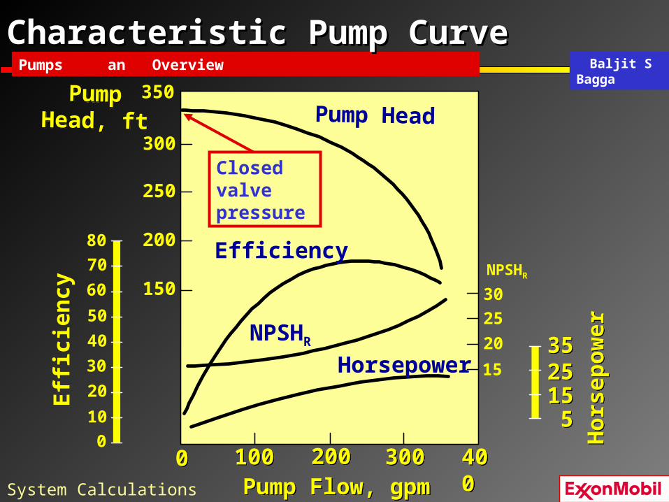
Characteristic Pump CurveCharacteristic Pump Curve
Pump Head
Efficiency
NPSHR
Hor
sep
ower
Hor
sep
ower
Eff
icie
ncy 50
40
30
20
60
70
80
10
0
350
300
250
200
150
200200100100 300300 40040000
151525253535
55
Horsepower
PumpHead, ftPump
Head, ft
Closed valve pressure
Pump Flow, gpmPump Flow, gpm
NPSHR
30
25
20
15
System Calculations

Baljit S BaggaPumps an Overview
Characteristic Pump CurveCharacteristic Pump Curve
Pump Head
Efficiency
NPSHR
kWkWEff
icie
ncy 50
40
30
20
60
70
80
10
0
100
80
60
40
20
50502525 7575 10010000
101015152020
55
Horsepower
PumpHead, m
PumpHead, m
m3/hrm3/hr
Closed valve pressure
NPSHR
10
8
6
4
System Calculations

Baljit S BaggaPumps an Overview
Performance CurvesPerformance Curves
Pump curves show:• Head vs. capacity
– For a range of impeller diameters– At design speed only
• Horsepower– For a range of impeller diameters– At design specific gravity
• NPSH required vs. flow rate• Efficiency map
– Best-efficiency point (BEP)– Efficiency decreases as
• Flow rate increases or decreases
• Impeller diameter is reducedSystem Calculations

Baljit S BaggaPumps an Overview
Typical Performance CurveTypical Performance Curve
Closed valve head or “shut-off” head
BEP
*
System Calculations

Baljit S BaggaPumps an Overview
Pump PowerPump Power
Hydraulic PowerEfficiency
Brake Power =
Hydraulic Power (hp) = Q(gpm) x H (ft) x SG
3960
Hydraulic Power (kW) = Q(m3/hr) x H (m) x SG
368
Power required for the fluid
Brake Power (bhp) =Q(gpm) x P (psi)
1714 x Eff
Brake Power (kW) =Q(m3/hr) x P (kPa)
37.5 x Eff
Power required at the pump shaft
*
System Calculations

Baljit S BaggaPumps an Overview
Net Positive Suction Head Net Positive Suction Head RequiredRequired
NPSHR
Temperature
Pre
ssur
e
NPSHR = Head loss (in meters or feet) of pumped fluid from the suction flange to the impeller eye or suction valve
Head loss (in meters or feet) of pumped fluid from the suction flange to the impeller eye or suction valve
P {
System Calculations

Baljit S BaggaPumps an Overview
Net Positive Suction Head Net Positive Suction Head AvailableAvailable
h1
P1
Suction Head, HS = P1 + h1 - LP1
NPSHA = HS - PVP
= P1 + h1 - LP1 - PVP
(pressure units must be converted to head units)
Suction Head, HS = P1 + h1 - LP1
NPSHA = HS - PVP
= P1 + h1 - LP1 - PVP
(pressure units must be converted to head units)
NPSHA must be greater than NPSHR to avoid cavitation

Baljit S BaggaPumps an Overview
NPSH Available for Reciprocating NPSH Available for Reciprocating PumpsPumps
h1
P1
Suction Pressure, HS = P1 + h1 - LP1 - Laccel
NPSHA = HS - PVP
= P1 + h1 - LP1 - Laccel - PVP
(pressure units must be converted to head units)
Suction Pressure, HS = P1 + h1 - LP1 - Laccel
NPSHA = HS - PVP
= P1 + h1 - LP1 - Laccel - PVP
(pressure units must be converted to head units)
NPSHA must be greater than NPSHR to avoid cavitation
Additional head loss due to accelerating flow
System Calculations

Baljit S BaggaPumps an Overview
Net Positive Suction HeadNet Positive Suction Head
• NPSHA =
– (Total suction head) - (flowing liquid vapor pressure)
– Converted to head units, in absolute pressure
• NPSHR =
– Head required by pump manufacturer
• If NPSHA > NPSHR no vaporization
• if NPSHA < NPSHR vaporization and CAVITATION
Acceleration and velocity effects should be considered in rigorous analyses.

Baljit S BaggaPumps an Overview
Net Positive Suction HeadNet Positive Suction Head
NPSH & CAVITATION• NPSH as the total suction head in feet absolute, determined
at the suction nozzle and corrected to datum, less the vapor pressure of the liquid in feet absolute. – NPSHA is defined as static head + surface pressure head - the
vapor pressure of your product - loss in the piping, valves and fittings
– This is the minimum head required to stop the pump from caviating.
• Cavitation means that cavities are forming in the liquid that we are pumping. This causes.– loss in capacity. – loss of pump head (pressure) – Efficiency Loss. – Noise, Vibration, and damage to pump components.

Baljit S BaggaPumps an Overview
Cavitation in an ImpellerCavitation in an Impeller
Note: Cavitation can also damage plungers and valves in reciprocating pumps
LIQUID
Vaporbubblesform
Bubbles collapse violently as pressure increases:DAMAGE TO SHROUDSAND VANES
*
Produces a “Rattling stones”
sound
NPSHA < NPSHR
Temperature
Pre
ssur
e
System Calculations

Baljit S BaggaPumps an Overview
CavitationCavitation
• Occurs when NPSHA < NPSHR
• Bubbles of vapor form in suction passages• Bubbles collapse violently when they reach a
point of higher pressure• Results:
– Pitting of impeller, sometimes severe– Noise, sound of “rattling stones”
• Damage– Greater with single component liquids, e.g. water– Multi-component liquids do not re-condense so
suddenly. However, head/flow capacity loss will result.
*
System Calculations

Baljit S BaggaPumps an Overview
Surveillance - Eliminating CavitationSurveillance - Eliminating Cavitation
1. Increase NPSHA
– Elevate the supply vessel or lower the pump (increase elevation differential)
– Shorten the suction piping or increase diameter (reduce suction friction losses)
– Reduce fluid temperature (reduce PV)
– Use a booster pump
System Calculations

Baljit S BaggaPumps an Overview
Surveillance - Eliminating CavitationSurveillance - Eliminating Cavitation
2. Reduce NPSHR
– Increase throttling in the discharge line, this action will reduce rate and increase suction pressure
– Use an oversized pump or double-suction pump– Use an impeller with a larger eye
System Calculations

Baljit S BaggaPumps an Overview
Impeller Diameter ChangesImpeller Diameter Changes
• Increase head/capacity • Decrease head
– To reduce power consumption– To reduce maximum discharge
pressure
Why Change Impellers?
Affinity Laws:
These relationships are approximate.Use manufactures performance curve when possible
1
212 D
DQQ
2
1
212 D
DHH
3
1
212 D
DBHPBHP
*
System Calculations

Baljit S BaggaPumps an Overview
Characteristics of Pumps in SeriesCharacteristics of Pumps in Series
• At any given capacity (flow rate) Q,HT = H1 + H2 + ... + Hn
• New operating point where be where the system curve intersects the total head curve.
Figure 15System Calculations

Baljit S BaggaPumps an Overview
Characteristics of Parallel PumpsCharacteristics of Parallel Pumps
Figure 17
• New operating point where the system curve intersects the total head curve.
• Note: Two pumps in parallel do not have twice the capacity of a single pump!!
System Calculations

Baljit S BaggaPumps an Overview
Water Injection PumpWater Injection Pump
Pulsation Dampeners
Discharge Relief
Valve
SuctionDischarge
Electric Motor
System Calculations

Baljit S BaggaPumps an Overview
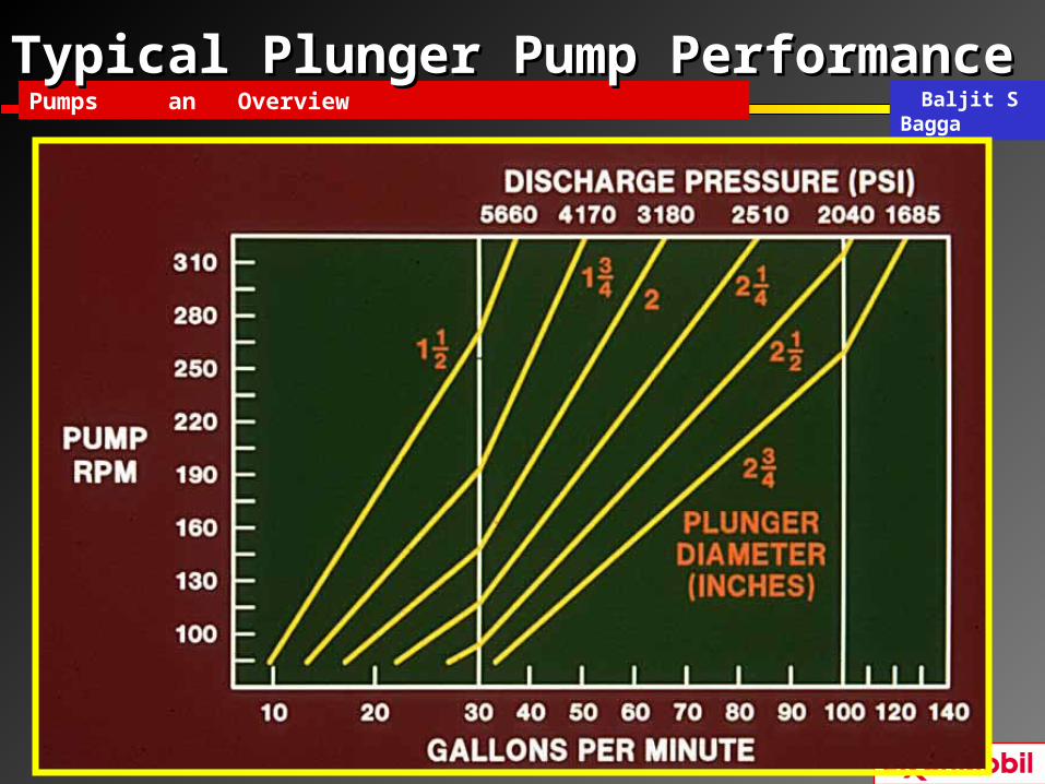
Head and Flow RateHead and Flow Rate
Basic Pump Performance at Constant Speed
Capacity
Hea
d
CENTRIFUGAL
CapacityCapacity
Hea
dH
ead
POSITIVE DISPLACEMENT
System Calculations
Baljit S BaggaPumps an Overview
Typical Plunger Pump Typical Plunger Pump PerformancePerformance

Baljit S BaggaPumps an Overview
TopicsTopics• Pump Purpose• Pump Types and Major Components• Fundamentals of Pumps• Pump System Calculations• Driver Choices
• Installation Issues and Surveillance– Control Systems– Viscosity Effects– Surveillance
• Pump Selections• Summary• Class problem

Baljit S BaggaPumps an Overview
Common Control SystemsCommon Control Systems
Control SystemsSingle Centrifugal Pumps• Throttle discharge flow
– Most common
• Variable speed– Requires a variable speed driver !– Remember, that pump curves are generally for one
operating speed
• Recirculation control– use with caution for centrifugal pumps– possible high power consumption, increased fluid temp
• Suction throttling should never be used– Could cause cavitation
*
Control System

Baljit S BaggaPumps an Overview
Common Control Systems (cont’d)Common Control Systems (cont’d)
• Centrifugal pumps must be protected against low-flow condition– Below minimum flow, pump may overheat, cavitation and seal
damage can occur.
• Minimum flow is normally 25 to 30% of flow at BEP (Best Efficiency Point)
*
Control System

Baljit S BaggaPumps an Overview
Centrifugal Pump Protection Against Low-Centrifugal Pump Protection Against Low-FlowFlow
Figure 18
Control System

Baljit S BaggaPumps an Overview
Caution - Pumps in SeriesCaution - Pumps in Series
• System design pressure must be suitable for the shutoff pressure of both pumps combined
• Extra controls and a safety valve may be required
• System design pressure must be suitable for the shutoff pressure of both pumps combined
• Extra controls and a safety valve may be required
Figure 16Control System

Baljit S BaggaPumps an Overview
Caution - Pumps In ParallelCaution - Pumps In Parallel
• Parallel operation can result in unbalanced flow, with less than minimum flow in one pump
• This can occur if curves are flat, and– Pump speeds are
different– Impellers are not
identical
• Parallel operation can result in unbalanced flow, with less than minimum flow in one pump
• This can occur if curves are flat, and– Pump speeds are
different– Impellers are not
identical
*
Control System

Baljit S BaggaPumps an Overview
Controls - Pumps in ParallelControls - Pumps in Parallel
If natural flow balancing cannot be guaranteed:
Figure 20
Figure 19
or separate minimum flow recycle controls
Use separate flow controllers,
Control System

Baljit S BaggaPumps an Overview
Protecting Reciprocating PumpsProtecting Reciprocating Pumps
PT
Pressure sensor detects high pressure from closed block valve and opens a bypass to keep pressure within acceptable limits
Control System

Baljit S BaggaPumps an Overview
Viscosity Effects On Pump Viscosity Effects On Pump PerformancePerformance
• Lower efficiency• Reduced head• Reduced capacity
Viscosity EffectsViscosity EffectsHigher viscosity results in:
} More Driver Power Required
Centrifugals Reciprocating
Water, Alcohol Always preferred Seldom used
Crude Oil, TEG Always preferred Seldom used
Heavy Crude Oil Head capacity begins to deteriorate Seldom used
Crankcase Oils Significant performance fall-off Sometimes used
First Cul Molasses Seldom used Generally preferred
Asphalt Never used Always used
*
Viscosity

Baljit S BaggaPumps an Overview
Surveillance Considerations – PumpsSurveillance Considerations – Pumps
Surveillance
• Vibration on plunger pumps– Vibration monitors for shut down device– Leak detection sensors on hydrocarbon fluids
(Piper Alpha disaster on a plunger pump)
• Vibration monitors on critical centrifugal pumps– Detect impeller wear, trash, or severe cavitation– Alarm for call out to check pump
Surveillance

Baljit S BaggaPumps an Overview
Surveillance Considerations – Pump SealsSurveillance Considerations – Pump Seals
• Packing used on water– Periodic adjustment required
• Mechanical seals on high pressure or flammable fluids– Trash or debris ruins seal face, use strainers or
filters
– Use flush line to eliminate leakage mess at seal
– Use flush line to recover hazardous leakage, such as H2S
Surveillance

Baljit S BaggaPumps an Overview
TopicsTopics
• Pump Purpose• Pump Types and Major Components• Fundamentals of Pumps• Pump System Calculations• Driver Choices• Installation Issues and Surveillance
• Pump Selections• Summary• Class Problem

Baljit S BaggaPumps an Overview
How Do I Select a Pump?How Do I Select a Pump?
• What are the Issues?– Flow– Required head– Upstream and downstream losses– NPSHA vs. NPSHR
– Installation ( series or parallel )– Controls– Other?
• Pump selection guide
Selection

Baljit S BaggaPumps an Overview
Pump Selection GuidePump Selection Guide
Selection

Baljit S BaggaPumps an Overview
TopicsTopics
• Pump purpose• Pump types and major components• Fundamentals of pumps• Pump System calculations• Driver choices• Installation Issues and Surveillance• Pump selections
• Summary• Class problem

Baljit S BaggaPumps an Overview
SUMMARY: PUMPSSUMMARY: PUMPS
• Pump performance is determined by flow and head (P)
• Head relates to pressure based on the density of the fluid
• Sufficient NPSHA prevents cavitation
• Pump curve required for centrifugal pump application
• Pumps can be centrifugal or reciprocating
• Pump performance is determined by flow and head (P)
• Head relates to pressure based on the density of the fluid
• Sufficient NPSHA prevents cavitation
• Pump curve required for centrifugal pump application
• Pumps can be centrifugal or reciprocating
Summary

Baljit S BaggaPumps an Overview
Centrifugal Pump CharacteristicsCentrifugal Pump Characteristics
• Main pump type in upstream operations
• Initial cost is less than for plunger pumps for most applications.
• Require less space than plunger pumps
• Lower operating costs than plunger pumps
• May be directly connected to electric motors or turbines (or the speed reducers)
• Have no reciprocating parts or valves and thus have a non-pulsating discharge
*
Selection

Baljit S BaggaPumps an Overview
Reciprocating Pump Reciprocating Pump CharacteristicsCharacteristics
• Can achieve high discharge pressures• Can offer precise flow control• Small to medium capacity• High volumetric efficiency• Pulsating discharge• Higher costs• Higher maintenance
• Can achieve high discharge pressures• Can offer precise flow control• Small to medium capacity• High volumetric efficiency• Pulsating discharge• Higher costs• Higher maintenance
*
Selection

Baljit S BaggaPumps an Overview
Pump ReferencesPump References
SUBJECT: PLAYING WITH A FEW PUMP TERMS • In any discussion of centrifugal pumps you will find
that there are several terms that are interrelated:
• Head , Capacity, Horsepower & Efficiency
• TDH = the total discharge head measured in feet / meter
• GPM = gallons per minute / liters per second.
• HP = horsepower required (or KW).
• Efficiency - defined as horsepower (water horsepower) out of the pump divided by the horsepower (brake horsepower) into the pump.
These numbers are shown on pump print and Nameplate.

Baljit S BaggaPumps an Overview
Pump ReferencesPump References
• APIs – 610 (Centrifugal Pumps), 674 (Reciprocating)
• APIs – 675 (C.V. Metering), 676 (Rotary Pumps)
• Upstream Machinery GPs • - GP 10-01-01 Centrifugal Pumps for Petrochem O&G Ind.
• - GP 10-01-02 Centrifugal Pumps (ANSI)
• - GP 10-01-04 Centrifugal Pumps for Non-HC Gen. Plant Services
• - GP 10-01-05 Centrifugal Pumps Subm. Motor for LNG Services
• - GP 10-02-04 Centrifugal Fire Pumps (NFPA)
• - GP 10-02-05 P.D. Pumps (Rotary - Multiphase Twin Rotor)
• - GP 10-02-06 Upstream P.D. Pumps (Reciprocating)

Baljit S BaggaPumps an Overview
TopicsTopics
• Pump Purpose• Pump Types and Major Components• Fundamentals of Pumps• Pump System Calculations• Driver Choices• Pump Installations• Pump Selections• Summary
• Class Problem

Baljit S BaggaPumps an Overview
SimplifiedSimplified Pump hydraulic sketchPump hydraulic sketch
FE
Pipe Fric lossSuction & Dis
Static Gain CV loss
Static Loss
Eqipment Loss
Strainer Loss
Flow Element
(FE) Loss
Valve Loss
Psuction
Low Liq Level
Pdestination
Rated = 200 gpm @ Head = 300 ft
T/L Elev
Pump C/L
Grade
Hi Liq Level

Baljit S BaggaPumps an Overview
Hydraulics TrainingHydraulics Training
KEY CALCULATION PARAMETERS
• Liquid Physical properties
• Cavitation and NPSH
• Friction loss
• Flow meter and control valve loss
• Equipment loss
• Elevation change (final/intermediate elevation)
• Exit Conditions

Baljit S BaggaPumps an Overview
Pump ProblemPump Problem
• To provide good control of the oil export process, a discharge control valve should be added to the flow path. The head loss of the discharge control valve should be approximately 30% of the frictional head loss of the export flowline.
• Determine the system head, the required pump discharge pressure when the control valve is added to the existing flowline and calculate the required BHP for the oil export pump. Do the calculations for Ramp-up, Design, and Abandonment.
Baljit S BaggaPumps an Overview
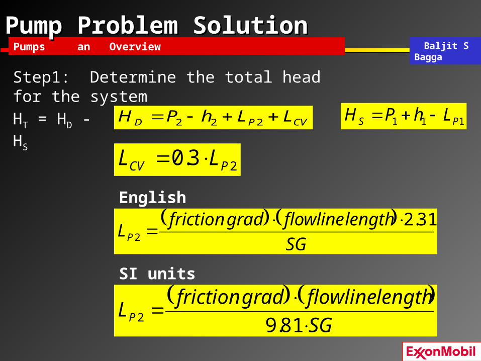
Pump Problem SolutionPump Problem Solution
English units
SI units
Step1: Determine the total head for the system
23.0 PCV LL
SG
lengthflowlinegradfrictionLP
31.22
SG
lengthflowlinegradfrictionLP
81.92
CVPD LLhPH 222 111 PS LhPH HT = HD - HS

Baljit S BaggaPumps an Overview
Pump Problem SolutionPump Problem Solution
English units
SI units
Step 1(cont’d): Determine the total head for the system 212 3.1
31.2P
suctiondeliverysDT Lhh
SG
PPHHH
212 3.181.9 P
suctiondeliverySDT Lhh
SG
PPHHH
*
English units Flowrate(gpm)
Suction P(psia)
Discharge P(psia)
System Head(ft-lbf/lbm)
Power (Hp)
Ramp-Up 1196 15 219Design 4823 15 2047Abandonment 613 15 118
SI units Flowrate(m3/min)
Suction P(kPa)
Discharge P(kPa)
System Head(m)
Power (kW)
Ramp-Up 4.5 103 66Design 18.3 103 677Abandonment 2.3 103 37

Baljit S BaggaPumps an Overview
Pump Problem SolutionPump Problem Solution
Step 2: Determine the pump differential pressure
English units
SI units SGmHkPaP Tpump 81.9)()(
SGftHpsiP Tpump 433.0)(
*

Baljit S BaggaPumps an Overview
Pump Problem SolutionPump Problem Solution
Step 3: Determine the pump discharge pressure
English units SI unitspsiaPP pumpedisch 15arg kPaPP pumpedisch 4.103arg
*
English units Flowrate(gpm)
Suction P(psia)
Discharge P(psia)
System Head(ft-lbf/lbm)
Power (Hp)
Ramp-Up 1196 15 63 219Design 4823 15 724 2047Abandonment 613 15 27 118
SI units Flowrate(m3/min)
Suction P(kPa)
Discharge P(kPa)
System Head(m)
Power (kW)
Ramp-Up 4.5 103 430 66Design 18.3 103 5435 677Abandonment 2.3 103 195 37

Baljit S BaggaPumps an Overview
Pump Problem SolutionPump Problem Solution
Step 4: Determine the pump brake power, assuming pump eff.= 75%English units SI units
75.01715
)()(
psiaPgpmV
BHP
75.060
)()min(3
kPaPmVBP
*
English units Flowrate(gpm)
Suction P(psia)
Discharge P(psia)
System Head(ft-lbf/lbm)
Power (Hp)
Ramp-Up 1196 15 63 219 73Design 4823 15 724 2047 2773Abandonment 613 15 27 118 20
SI units Flowrate(m3/min)
Suction P(kPa)
Discharge P(kPa)
System Head(m)
Power (kW)
Ramp-Up 4.5 103 430 66 54Design 18.3 103 5435 677 2247Abandonment 2.3 103 195 37 15

Baljit S BaggaPumps an Overview
PUMPS an OverviewPUMPS an Overview
Any Questions ?
• What is the closest & dearest Pump to you?
• Difference between Pump and Compressor
• API 610 Centrifugal Pumps Types, Classification and Designations
• Pump Technology Advancements (Sub-sea Multiphase pumping)

Baljit S BaggaPumps an Overview
PUMPS an OverviewPUMPS an Overview
API Standard 610 / ISO 13709 - The pumps described in this International Standard are classified and designated as shown in Table 1 — Pump classification type identification and Pump type Orientation Type code (18 types)
Overhung (6 types)OH1 - Foot-mounted OH1OH2 - Horizontal Centreline Flexibly coupled supported OH2OH3 - Vertical in-line with bearing bracket OH3OH4 - Rigidly coupled Vertical in-line OH4OH5 - Vertical in-line OH5OH6 - Overhung Close-coupled High-speed integrally geared OH6
Between Bearings (5 types)BB1 - Axially split BB1BB2 - 1- and 2-stage Radially split BB2BB3 - Axially split BB3BB4 - Single casing BB4BB5 - Between-bearings Multistage Radially split Double casing BB5
Vertical Shafts (7 types)VS1 - Diffuser VS1VS2 - Discharge through Volute VS2VS3 - Column Axial flow VS3VS4 - Line shaft VS4VS5 - Single casing Separate discharge Cantilever VS5VS6 - Diffuser VS6VS7 - Centrifugal pumps Vertically suspended Double casing Volute VS7

Baljit S BaggaPumps an Overview
PUMPS an OverviewPUMPS an Overview
API Standard 610 / ISO 13709
4.2 Pump designations – and illustrations of the Overhung (6 types) of pumps
4.2.1 Pump type OH1 - Foot-mounted single-stage overhung pumps shall be designated pump type OH1. (This type does not meet all the requirements of this International Standard, see Table 2.) Figure 1 — Pump type OH1
4.2.2 Pump type OH2 - Centreline-mounted single-stage overhung pumps shall be designated pump type OH2. They have a single bearing housing to absorb all forces imposed upon the pump shaft and maintain rotor position during operation. The pumps are mounted on a baseplate and are flexibly coupled to their drivers. Figure 2 — Pump type OH2
4.2.3 Pump type OH3 - Vertical in-line single-stage overhung pumps with separate bearing brackets shall be designated pump type OH3. They have a bearing housing integral with the pump to absorb all pump loads. The driver is mounted on a support integral to the pump. The pumps and their drivers are flexibly coupled. Figure 3 — Pump type OH3
4.2.4 Pump type OH4 - Rigidly coupled vertical in-line single-stage overhung pumps shall be designated pump type OH4. Rigidly coupled pumps have their shaft rigidly coupled to the driver shaft. (This type does not meet all the requirements of this International Standard, see Table 2.) Figure 4 — Pump type OH4
4.2.5 Pump type OH5 - Close-coupled vertical in-line single-stage overhung pumps shall be designated pump type OH5. Close coupled pumps have their impellers mounted directly on the driver shaft. (This type does not meet all the requirements of this International Standard, see Table 2.) Figure 5 — Pump type OH5
4.2.6 Pump type OH6 - High-speed integral gear-driven single-stage overhung pumps shall be designated pump type OH6. These pumps have a speed increasing gearbox integral with the pump. The impeller is mounted directly to the gearbox output shaft. There is no coupling between the gearbox and pump; however, the gearbox is flexibly coupled to its driver. The pumps may be oriented vertically or horizontally. Figure 6 — Pump type OH6

Baljit S BaggaPumps an Overview
PUMPS an OverviewPUMPS an Overview
API Standard 610 / ISO 13709
4.2 Pump designations – and illustrations of the BB (5 types) of pumps
Between Bearings (5 types)
4.2.7 Pump type BB1 - Axially split one- and two-stage between-bearings pumps shall be designated pump type BB1.Fig 7
4.2.8 Pump type BB2 - Radially split one & two-stage between-bearings pumps shall be designated pump type BB2. Fig 8
4.2.9 Pump type BB3 - Axially split multistage between-bearings pumps shall be designated pump type BB3. Figure 9.
4.2.10 Pump type BB4 - Single-casing radially split multistage between-bearings pumps shall be designated pump type BB4. These pumps are also called ring-section pumps, segmental-ring pumps or tie-rod pumps. These pumps have a potential leakage path between each segment. (This type does not meet all the requirements of this Int. Std., see Table 2.) Fig.10
4.2.11 Pump type BB5 - Double-casing radially split multistage BB pumps (barrel pumps) shall be designated pump type BB5. Figure 11

Baljit S BaggaPumps an Overview
PUMPS an OverviewPUMPS an Overview
API Standard 610 / ISO 13709
4.2 Pump designations – and illustrations of Vertical Shaft (7 types) pumps
4.2.12 Pump type VS1 - Wet pit, vertically suspended, single-casing diffuser pumps with discharge through the column designated type VS1. Fig.12
4.2.13 Pump type VS2 - Wet pit, vertically suspended single-casing volute pumps with discharge through the column designated type VS2. Fig.13
4.2.14 Pump type VS3 - Wet pit, vertically suspended, single-casing axial-flow pumps with discharge through the column designated type VS3. Fig.14
4.2.15 Pump type VS4 - Vertically suspended, single-casing volute line-shaft driven sump pumps designated pump type VS4. Fig.15
4.2.16 Pump type VS5 - Vertically suspended cantilever sump pumps shall be designated pump type VS5. Fig. 16.
4.2.17 Pump type VS6 - Double-casing diffuser vertically suspended pumps shall be designated pump type VS6. Fig. 17.
4.2.18 Pump type VS7 - Double-casing volute vertically suspended pumps shall be designated pump type VS7. Fig. 18

Baljit S BaggaPumps an Overview
PUMPS an OverviewPUMPS an Overview
Diana/Hoover Subsea Development

Baljit S BaggaPumps an Overview
PUMPS an OverviewPUMPS an Overview
Diana/Hoover Subsea Development
Diana/Hoover Subsea Development