Pumps and Pipes ©2012 Dr. B. C. Paul Note- These slides refer to many concepts commonly understood...
89
Pumps and Pipes ©2012 Dr. B. C. Paul Note- These slides refer to many concepts commonly understood by people with training in the field and published in numerous textbooks no single one of which was used in compiling these slides. These slides do contain screenshots of the program Slysel which was developed by GIW. Credit for the program is attributed accordingly. Some figures were taken from “The Centrifugal Pump” by Grundfos Research and Technology
-
Upload
ralph-lamb -
Category
Documents
-
view
214 -
download
0
Transcript of Pumps and Pipes ©2012 Dr. B. C. Paul Note- These slides refer to many concepts commonly understood...

Pumps and Pipes
©2012 Dr. B. C. Paul
Note- These slides refer to many concepts commonly understood by people with training in the field and published in numerous textbooks no single one of
which was used in compiling these slides. These slides do contain screenshots of the program Slysel which was developed by GIW. Credit for the program is attributed accordingly. Some figures were taken from “The
Centrifugal Pump” by Grundfos Research and Technology
Our Materials Handling Problem
• Water shows up in a lot of places in mines and we would rather have it someplace else
• Water is used as a carrier in a lot of our mining and mineral processing operations.
• We get water into pipes and pump it around• That is what this unit discusses

Assumed
• You have or are taking Fluid Mechanics• You understand things like
• Laminar and turbulent flow• Reynolds number• What the Bernoulli Equation is
• Because we are not covering these fluid fundamentals

Basic Equation for Our Task is Bernoulli's Equation (with slight
modifications for non-ideal fluids)
zVPHHzVgcgc
Ppf 2
2
221
2
1
221
Basically this is Newton’s second law for incompressible fluid flow
If you have two points – point 1 and point 2 – energy (indicated by pressure)will be conserved between the two points.

Translating the Equation
zVPHHzVgcgc
Ppf 2
2
221
2
1
221
Z is the elevation
If the fluid is higher at Z1 than at Z2 the there is more potential energy due toElevation at point 1 than at point 2
We need to pick some arbitrary “datum” from which to measure Z. People oftenPick sea level, surface level, or some mine level.

More Translation
zVPHHzVgcgc
Ppf 2
2
221
2
1
221
gV2
2 The term is called velocity head – fluid in motion has energyFrom that motion. The energy is measured by the velocitySquared divided by 2 times the gravitational constant g.

We Are Still Translating
zVPHHzVgcgc
Ppf 2
2
221
2
1
221
Hf is the energy lost to friction. Friction results from drag on the fluid as it movesOver the pipe surface, and the fluid dragging on itself due to turbulance.
Hp is the energy added to the system by the action of a pump.
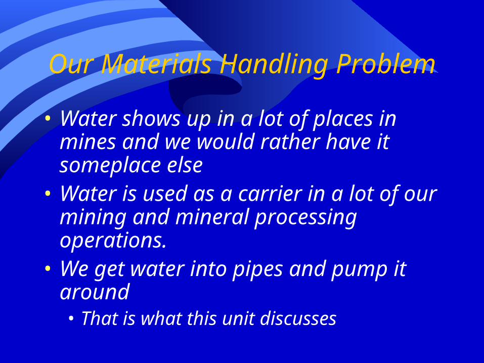
The Last Term in Our Translation
zVPHHzVgcgc
Ppf 2
2
221
2
1
221
c
PP is the pressure the fluid is already under at some point
C is a constant to make sure the pressure term is in the sameUnits as all the other terms in the equation. (We often use unitsOf the pressure from a column of water 1 ft tall – ie – ft of waterGage).
Often the pipe system is open to the air at both ends – in this caseThere is no net pressure at either end and the term goes away.Sometimes in processing we may be pumping water into a deviceThat requires the water at some pressure – now its not zero.
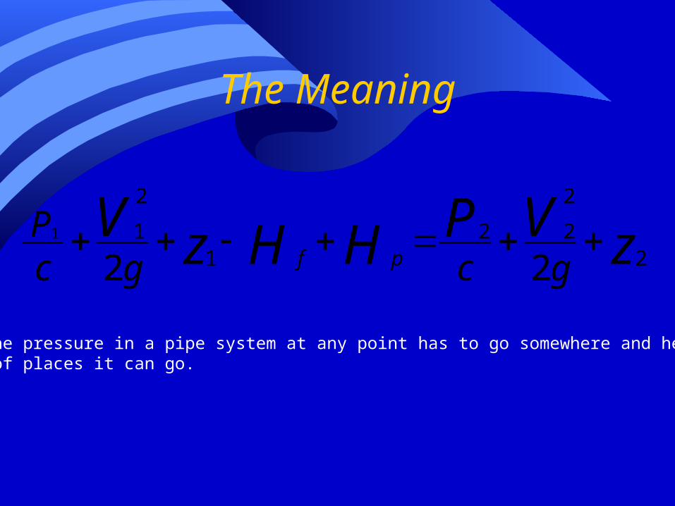
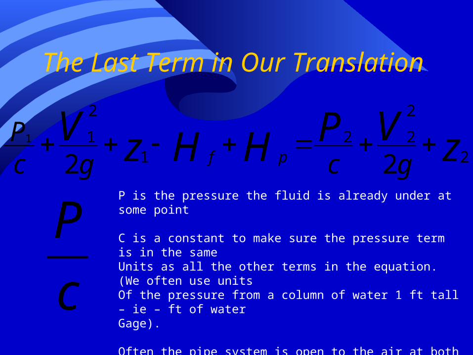
The Meaning
zVPHHzVgcgc
Ppf 2
2
221
2
1
221
All the pressure in a pipe system at any point has to go somewhere and here is aList of places it can go.

Lets Put This Equation to Work(and meet a new software friend while we
are at it)
water
pump
Ditch on thesurface
Once upon a time there was a mine that neededTo pump water out of a collection sump in theMine into a drainage ditch on the surface.
Back flow prevention valve

Fire-Up Slysel by GIW (GIW is a pump company)
(Metso puts out a similar programCalled Pumpdim)

Oh – Way Cool – The Program Starts
Click Ok thatYou are notGoing to stealThe sourceCode or sueThem if yourDesign doesNot work out.

Design Generally Will Require You to work through a series of tabbed inputs and outputs – left
to right

File and Help Have Drop Down Menus
Most important is your ability to save andOpen specific projects saved in filenamesThat you chose.

The Help Options
Pump manuals lets you reviewLiterature on pumps made byGIW
The documentation area letsYou get to the program usersManual
You can regularly go to the GIWWebsite to update Slysel

Put In Our Title Information that Will Appear on Output Reports

Pick Your Units

Usually Best to Just Take the Default Program Operations
Options

Economics are An Important Selection Criteria
Input the interest rate onCapital. 10% is typical for“levered” investments butAll investor equity in MiningIs more like 15 to 18%.
GIW probably has best guessOn rebuild cost
Hours of operation is one ofYour design plan itemsBelt drive pumps are about 90% efficiency in moving
Power from motor to pump (electrical consumption isOften a major cost)
Your cost for power. Program calculates headloss but quick estimate gets costs inThe ballpark.

Click the Next Tab to Describe Your Piping System
Two major relationshipsBetween pumps andSumps.
1- water level is higherThan pump.
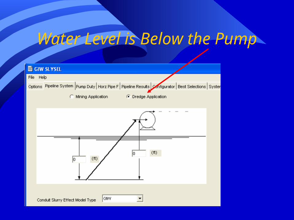
Water Level is Below the Pump
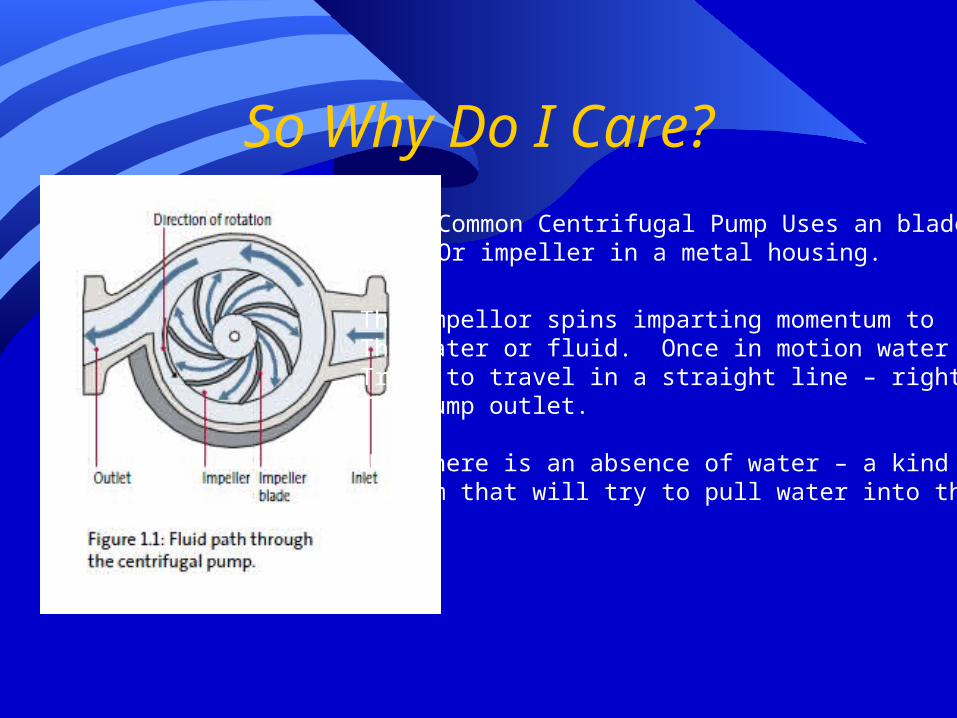
So Why Do I Care?
Common Centrifugal Pump Uses an bladeOr impeller in a metal housing.
The impellor spins imparting momentum toThe water or fluid. Once in motion waterTries to travel in a straight line – right throughThe pump outlet.
Now there is an absence of water – a kind ofVacuum that will try to pull water into thePump.

The Pressure Difference
On the outside there is the weightOf the atmosphere plus the heightOf the water column above thePump pushing down.
On the insideThere is aPartialvacuum
Water moves from higher pressure outside the pump toLower pressure inside and refills the pump.

You Did Say the Pressure Was Higher Outside?
• Well – maybe not• Things that push back from inside the
pump• What ever fluid pressure that remains – no
pump draws a perfect vacuum – a zero.• Vapor pressure of the liquid (there are always
molecules trying to break away from the fluid – the hotter the fluid the more the pressure from the break-away molecules)

And In This Corner On the Outside
• The weight of the atmosphere• (of course the higher the elevation the lower that
is)
• The pressure in the tank• If there is no pressurized tank then its only the
weight of the atmosphere
• The pressure from the column of water above the pump.• But what if the water level is below the pump?
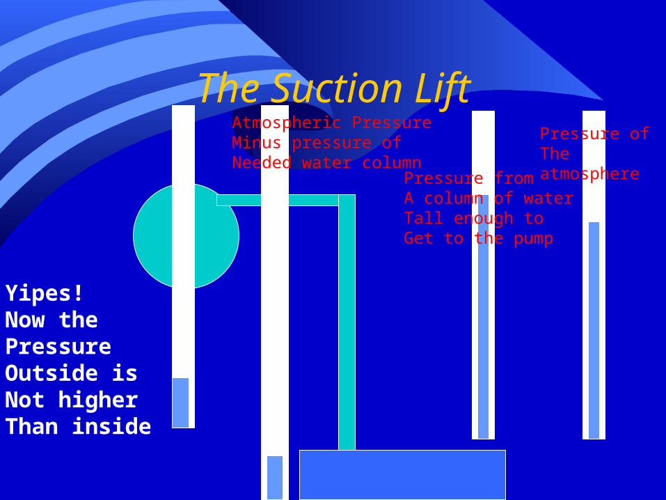
The Suction LiftPressure ofThe atmosphere
Pressure fromA column of waterTall enough toGet to the pump
Atmospheric PressureMinus pressure ofNeeded water column
Yipes!Now thePressureOutside isNot higherThan inside

Result
• No Water Flows into the pump
• This can also happen with hot liquids that have a lot of back-pressure in the pump from the vapor pressure of the fluid.

So Why Do I Care About Whether the Water Level is Above or Below My Pump
• If it is below I better check my suction lift or I may have a dry pump.
• (I also need to watch out if the atmospheric pressure is very low or the fluid has a very high vapor pressure)

Common Pipe Design
• Designs often have larger intake pipes than discharge pipes• Suction lift is absolutely limited by weight of
the atmosphere• Want to limit frictional losses even though
the choice may not be most economic• Have to make things work first

Enter My Basic Suction Lift Data
I have a pump intake point that will always be 3 feet underwater.
My sump has up to 5 feet of freeboard. I am using a large pump that stays aboveWater level.
My project elevation is 8000 feet which does reduceThe weight of the atmosphere above.
My pump is in anAbove water position

What Happens to Water When It is Discharged
• In this case I will discharge it into an open ditch at atmospheric pressure• Ie – gage pressure of
0
• In processing I might have a required pressure as I inject into a cyclone.
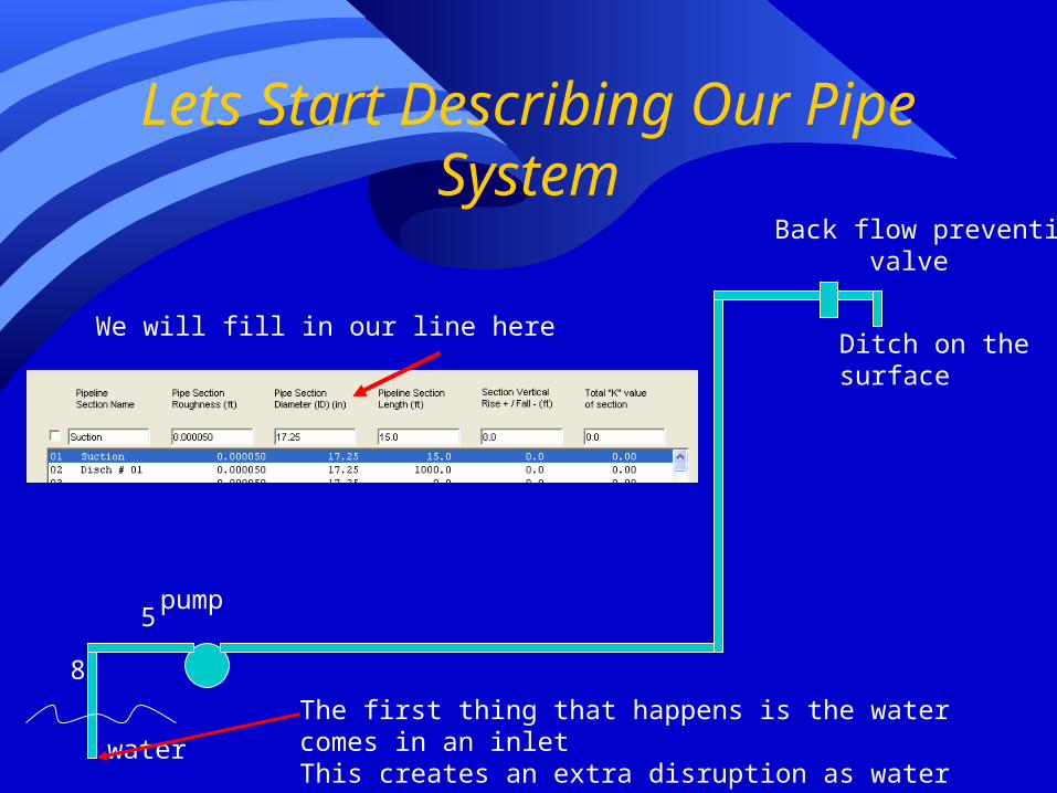
Lets Start Describing Our Pipe System
water
pump
Ditch on thesurface
Back flow prevention valve
The first thing that happens is the water comes in an inletThis creates an extra disruption as water swirls into a confinedEnvironment. We deal with a K factor.
We will fill in our line here
8
5

Describing Our Piping System
We highlight thePart of the systemWe will describeBefore startingThe input lineNote that when I type the name of the pipe portion
It goes immediately into the highlighted line.

Pipe Section RoughnessApplying the Stanton Diagram
In laminar flow frictionalLosses are a linearFactor of ReynoldsNumber.
gerPipeDiamet
PipeLengthf VH f 2
**2
Where the f from theStanton DiagramGoes into the DarcyWeisbach Equation
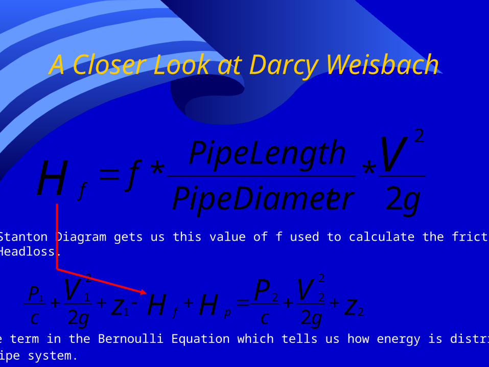
A Closer Look at Darcy Weisbach
gerPipeDiamet
PipeLengthf VH f 2
**2
Stanton Diagram gets us this value of f used to calculate the frictionalHeadloss.
zVPHHzVgcgc
Ppf 2
2
221
2
1
221
Hf is the term in the Bernoulli Equation which tells us how energy is distributed inA pump pipe system.

Back to Our Stanton Diagram
In Turbulent Flow overA perfectly smoothSurface the value off declines at an inclineAs a function ofReynolds Number

The Transition Zone
At a point that dependsOn disturbance of theWater the waterSuddenly starts churningAnd jumps fromLaminar to TurbulanceFlow.

Another Transition
Real pipe is neverFully smooth whichMeans bumps on theSides of the pipePertrude into theChurning and turbulentFluid.
At higher ReynoldsNumber these bumpsInto the turbulent fluidFully control the pipeFriction.
This area is called theWholly Rough Zone

The Wholly Rough Zone
In the Wholly Rough Zone the friction factor isA constant that depends only on the design ofThe pipe.
In pump and pipe problems almost all pumpedFlow is in the Wholly Rough Zone. Thus if youKnow what kind of pipe you have you knowYour friction factor.

Pipe Roughness In Slysel
Select the box with a right click
Left click to drop down a menu
Put the Curser on the commonValue line – out pops a sideMenu of friction factors forDifferent types of pipe
Left click on your type of pipe.
I’m going to assume HighDensity Polyethylene plasticPipe.
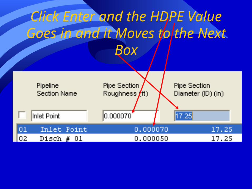
Click Enter and the HDPE Value Goes in and it Moves to the Next
Box

Oh the Nasty Catch
It wantsInternal pipediameter
Do the right click and menu trick to get aList of standard sizes.
My HDPE is 10 inch schedule 80.
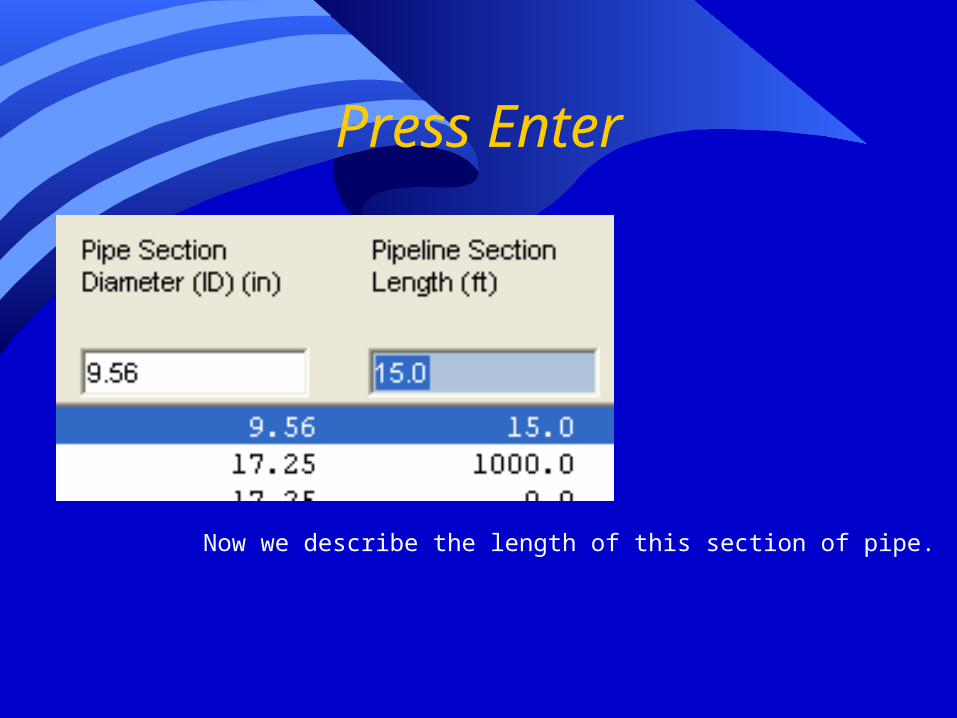
Press Enter
Now we describe the length of this section of pipe.

We Enter the Length and Rise for the first section of pipe
Our Last Challenge is that K value
K values are used to describe “shock” or minor losses such as in this case waterMoving from an open sump into the open end of a submerged pipe.

K Values
• Minor losses are described by the following equation
gK VH f 2*
2
K values depend on what is being encountered.
In our case it is water going from an open sump into a confined pipe.

Time for the Good Old Right Click Trick

And We Are Done With Our First Length of Pipe

Move to Our Second Section of Pipe
water
pump
Ditch on thesurface
Back flow prevention valve
5
This section of pipe hasNo rise in elevation
But it does have a 90Degree bend in a pieceOf pipe 8 to 10 inchesIn diameter (which is whyWe have to pick a K Factor)
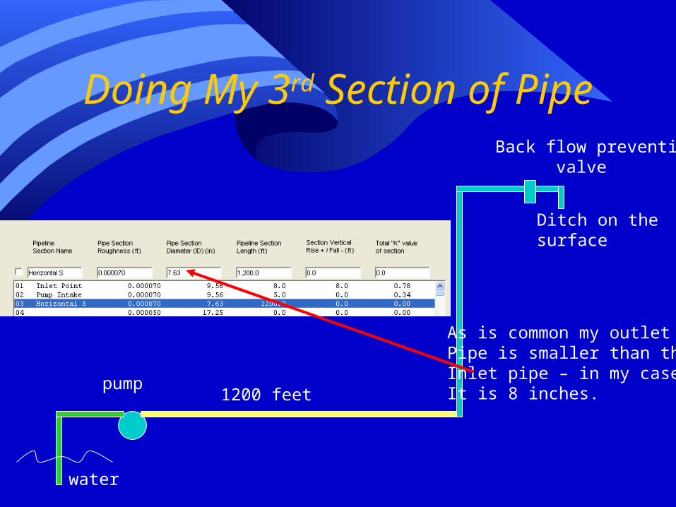
Doing My 3rd Section of Pipe
water
pump
Ditch on thesurface
Back flow prevention valve
As is common my outletPipe is smaller than theInlet pipe – in my caseIt is 8 inches.1200 feet

Now for My Lift to the Surface
water
pump
Ditch on thesurface
Back flow prevention valve
600 feet
In this case I have a90 degree elbow in aPiece of 8 inch pipe.

Enter My Next Section
water
pump
Ditch on thesurface
Back flow prevention valve250 ft.
This one features a gatevalve

Why A Gate Valve?
• The Case of the Illinois Quarry• There was a sump in the bottom of the
quarry that pumped water to the surface and into a ditch.
• They had a heavy rain. The pump worked and filled the ditch to where the pipe discharge was below the ditch water level.
• Then the power went out.

What Do You Call This?
Oh My Gosh It’s a Siphon!
They filled the quarry half way with waterAnd almost lost the equipment beforeGod had mercy on their poor stupid soulsAnd stopped the rain.
After that they put in a valve so they theyCould stop backflows.
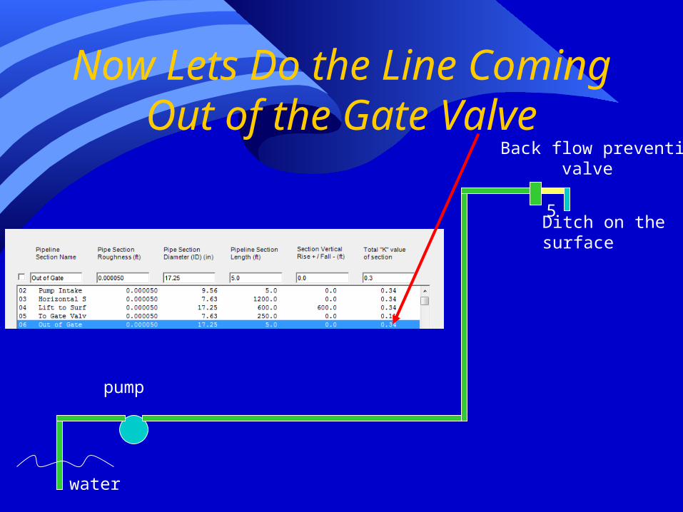
Now Lets Do the Line Coming Out of the Gate Valve
water
pump
Ditch on thesurface
Back flow prevention valve
5

Finishing My Pipeline
water
pump
Ditch on thesurface
Back flow prevention valve
2
Commentary #1
• Slysel’s menu includes K values for most common single minor losses• Of course for combinations the possibilities are
infinite
• I broke my pipe sections so that no section had any more than 1 minor loss
• I could have more than 1 minor loss in a section but then I would have to separately add up and enter the K values
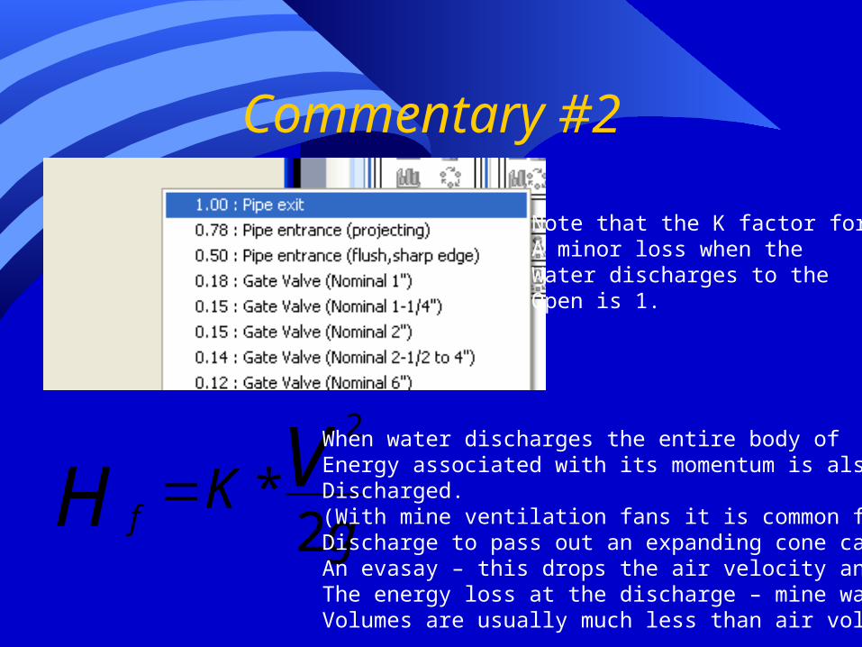
Commentary #2
Note that the K factor forA minor loss when theWater discharges to theOpen is 1.
gK VH f 2*
2
When water discharges the entire body ofEnergy associated with its momentum is alsoDischarged.(With mine ventilation fans it is common for theDischarge to pass out an expanding cone calledAn evasay – this drops the air velocity and cutsThe energy loss at the discharge – mine waterVolumes are usually much less than air volumes).

We Move Now to Pump Dutyor how much of what will we pump today

What Shall We Pump Today?
Note that the default properties of the liquid and slurry are for plain ordinary water.
We can use Slysel for selecting pumps for slurries but we won’t do that now.

Now For Entering How Much
I put in myQuantity of waterAnd then checkedTo let SlyselUse my pipeSystem toCalculate theRequired pumpHead.
It filled in a bunchOf other blanksIncluding myTotal HeadRequirements.

Commentary on Service Class
• Service class does not seem to have a definition that all agree on.• It has to do with how much of the time it
runs and how critical that it is• Things running more than about 2500
hours a year that are fairly critical seem likely to be called class 1 duty
• Class one pump duty will result in pumps being selected with tighter more critical specs.

You Can Filter and Limit Pump Choices
But we won’t do that now.
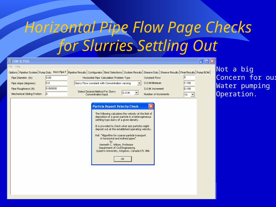
Horizontal Pipe Flow Page Checks for Slurries Settling Out
Not a bigConcern for ourWater pumpingOperation.

Pipeline Results is mostly on what happens with a settling
slurry
Again a lessCriticalParameter forA water pumpOperation.

Next Tab Gives You a Chance to Do Some Detail Pump Configurations
Your not wellTrained to doThat yet.

Now Lets See Which Pump it Picked? – Best Selections Tab
Ouch it says noStandard pumpMet ourCriteria.

So How Is this Selection Thing Suppose to Work?
The Centrifugal pump has spinningImpellers that can put out a givenAmount of energy. That could beHigh pressure for a small amountOf liquid – or low for a lot.Each Pump has a output curve such as this.

The Pipe System
Head
Water Volume
At very low flow there is almost no frictionalLoss, but there is still the pressure of the liftOf the water to overcome.

The Pipe System
Head
Water Volume
As the flow quantity increases, loss fromFriction (and velocity head) increase.Thus the shape of the pipe curve.

Hooking Pumps and Pipes Together in a System.
The systemOperates at theIntersection of thePump curve andThe pipe curve.
It is the only pointWhere both thePump and the pipeCan operate.

So Why Didn’t It Work for Us?
These are the operatingRanges for a bunch of GIWsPumps.
Getting 2500 GPM is easy
But the pumps only can putOut about 300 ft of head.(our static lift is 600 feet)

This is Us
Head
Water Volume
Pump Curve
Our Pipe Curve
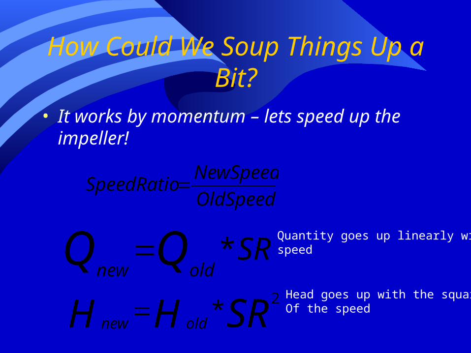
How Could We Soup Things Up a Bit?
• It works by momentum – lets speed up the impeller!
OldSpeed
NewSpeedSpeedRatio
SRQQoldnew*
SRHH oldnew
2*
Quantity goes up linearly withspeed
Head goes up with the squareOf the speed

Up – Up and Away Goes the Curve
Just one little problem –
Spinning impellersProduce back-thrustAgainst the bearings.
They have pumps sealsAround a rotatingShaft that have to work.
About 3600 RPM isHighest typical speed.I need a little more than4 times the head – meansI need around 8000 RPM
(You know – I don’t think I want to be near that pump when it runs).
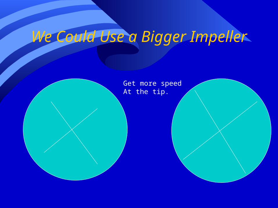
We Could Use a Bigger Impeller
Get more speedAt the tip.

Many Pump Curve Have Multiple Curves
They representPutting in biggerimpellers

Ouw- That Might Not Work
• I have a feeling I’m getting back to limits on thrust against bearings on the impeller shaft.
We might also have some impellerClearance and wear problems if there areParticles in the water larger than theImpeller to pump housing clearance.
(I found that out after one of my slurry pumpsLost most of its pressure after the first halfHour of operation).
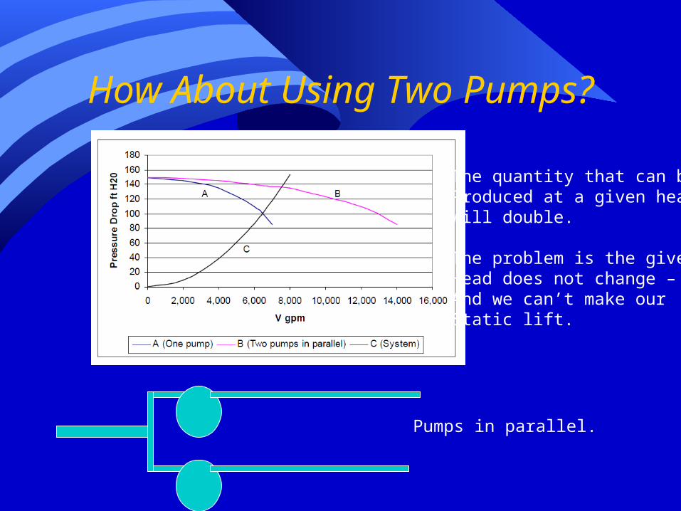
How About Using Two Pumps?
The quantity that can beProduced at a given headWill double.
The problem is the givenHead does not change –And we can’t make ourStatic lift.
Pumps in parallel.

Ok – How About Adding in Series
In this case the head adds
Multi-stage pumps areActually built for such applications

I Will Tell Slysel to Try 2 Pumps in Series

Now I Have Choices on the Best Selections Tab
Of course figuring out how to read this stuffMay be quite another matter.

Pump Codes
The first number is the pumpOutlet size
The second number is the pumpInlet size.
(Since my pipe sizes are 10 inletAnd 8 outlet – I’d like an 8X10)
Third number is the impellerDiameter.
Rest of the stuff is some realDetailed pump constructionCodes.

Slysel Lists Pumps by Effeciency
Here is my top 8X10 choice – I’m pick it.(It matches my chosen pipe sizes)
I’m running at a speedOf 1380 RPM with aPump Efficiency of 68%
I will require 345 HP to runThe system.

Highlight and Click
I get some design choices in the middle box(again details of pump construction are beyond our scope)

Now I Have A Report with Loads of Stuff In It.
I’m going to check toMake sure mySuction lift is not goingTo foul-up.
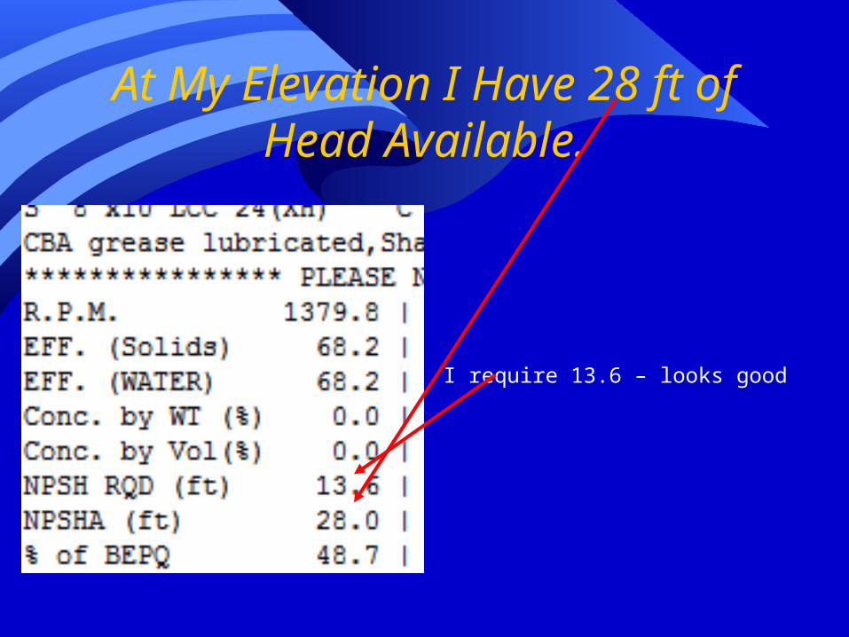
At My Elevation I Have 28 ft of Head Available.
I require 13.6 – looks good
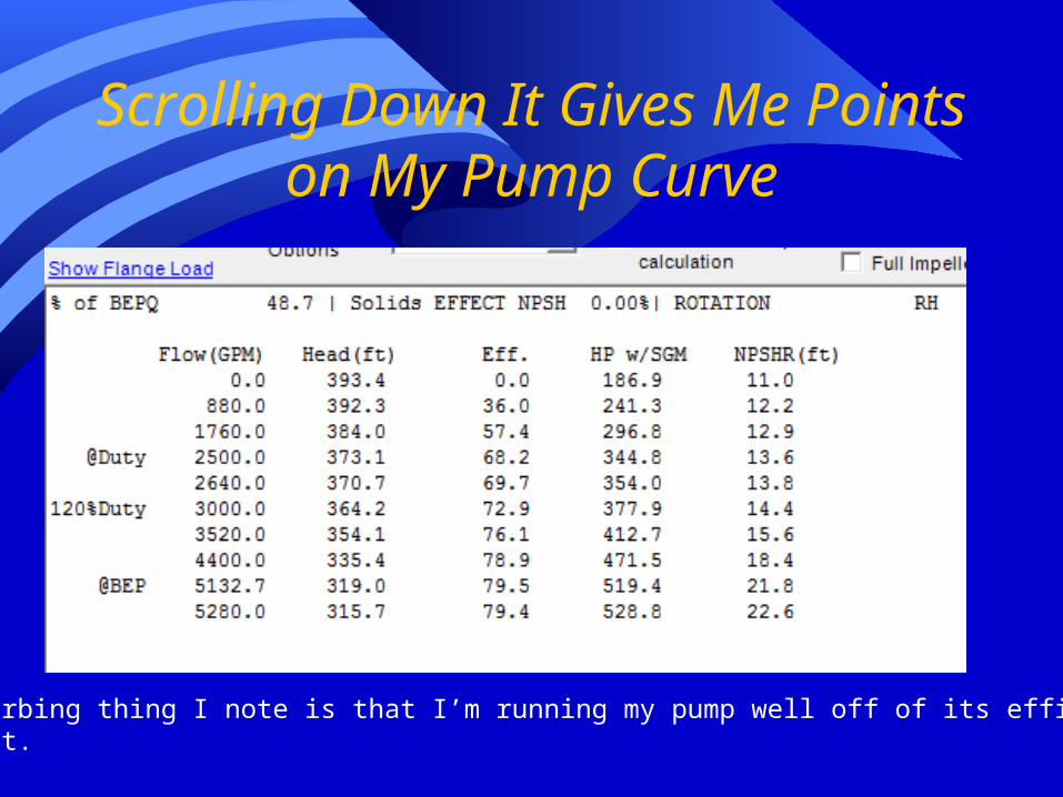
Scrolling Down It Gives Me Points on My Pump Curve
One disturbing thing I note is that I’m running my pump well off of its efficiencySweet spot.
This Sounds Like a Job for My Victims – Woops I Mean
Students• I arbitrarily picked 10 inch and 8 inch pipes• I arbitrarily picked 2 staged pumps• Work with Slysel to produce a higher pump
efficiency and lower total horsepower requirement.• Minimum requirement (break 75%)• Bonus points for the most efficient

Can Get Slysel for Yourself
• http://www.giwengr.com/GIWSLYSELusers.htm