PUMP S5AV 50-63 - Dana Brevini Fluid Power 050-063_en.pdf · CTP testing procedure ... and...
43
PUMP S5AV 50-63 SERVICE MANUAL
Transcript of PUMP S5AV 50-63 - Dana Brevini Fluid Power 050-063_en.pdf · CTP testing procedure ... and...

PUMPS5AV 50-63
SERVICE MANUAL

Page Intentionally left Blank

3S5AV 50-63 FOREWORD13/0040/001
Foreword
IndexForeword ....................................................................... 5
Layout and use of this manual ....................................................................... 4Notice ............................................................................................................. 4 Safety instructions .......................................................................................... 4Product identification and serial number ........................................................ 5Special tools ................................................................................................... 5
Exploded views and part lists ...................................... 6Ports and settings ........................................................ 9Troubleshooting .......................................................... 16Preliminary operations ............................................... 17Disassembly ................................................................ 18Assembly ..................................................................... 21Control mounting ........................................................ 24Through drive .............................................................. 29CLS+TP testing procedure .......................................... 34CTP testing procedure ................................................ 37PI+PC testing procedure ............................................. 38NC+PI+PC testing procedure ...................................... 39NC+PC testing procedure ........................................... 40NC+LS+TP3 testing procedure ................................... 41Storage and demolition .............................................. 42

4 S5AV 50-63FOREWORD 13/0040/001
ForewordLayout and use of this manualThe purpose of this manual is to provide the user with all the information required to ensure the proper disassembly and assembly Brevini Fluid Power S.p.A. products.It contains information concerning technical matters, assembly, operation and safety.Before carrying out any operations, operators and qualified technicians must read the instructions contained in this manual very carefully. In the event of any doubts over the correct interpretation of the instructions, please contact our offices for clarification.The contents of this manual comply with Directive 98/37/EC and has been written following the guidelines of the UNI 10893-2000 standard. It is forbidden to disclose, modify or use the contents of this manual for personal purposes.
NoticeDue to the continuous product developments, modifications and improvements Brevini Fluid Power S.p.A. will not be held responsible for any erroneous information or data that may lead to errors, indicated in catalogues, instructions, drawings, technical data and other data supplied by Brevini Fluid Power S.p.A.. Therefore, legal actions cannot be based on such material. Product development. Brevini Fluid Power S.p.A. reserves the right to make changes to its products, even for those already ordered, without notice.
In preparing the manual some simple pictograms have been chosen with the purpose of drawing the reader’s attention and making the consultation of the manual easier and more immediate.
DANGER Failure to comply with the instructions could result in damage to persons and property.
CAUTION Failure to comply with the instructions could lead to technical damage to the machine and/or system.
Safety instructions
The motor (or pump) may only be used or assembled on a machine by technicians who are adequately trained about its operation and the deriving dangers, using clothing and personal protective equipment ap-propriate.
Variations to the functional parameters of the mo-tor (or pump), pressure adjustments, demounting and refitting of parts not described in the operation and maintenance manual by unauthorized personnel shall relieve Brevini Fluid Power from all and every liability for deriving accidents or for failure to comply with the laws in merit.
The motor (or pump) must be started in compliance with the specific instructions in the “Installation and commissioning notes”.
During operation, the surface of the motor (or pump) can become dangerously hot. Avoid contact without gloves.
Before proceeding with any operation on the motor (or pump), Stop the machine and let it cool. Never carry out any operation whilst the pump is running.
Avoid release to the environment the oil contained in the motor housing (or pump housing) and in the circuit during disassembly.
Moving the motor (or pump) only as described in the operations of predisassembly.
Use the equipment listed in this manual to prevent damage to property and people.
Tighten all components with the torque indicated in the table and in the early stages of assembly.

5S5AV 50-63
X X X X X X X X X
Y Y / M M - S S S S S S B B
FOREWORD13/0040/001
Product identification and serial number
Special tools
Do not remove, alter or damage the identification plate.
Productdescription
Serial number
YY = Year of productionMM = Month of productionSSSSSS = Batch numberBB = Batch progressiv number
Each Brevini fluid power’s product is supplied with an identification data plate. The full identification of the product is made only through the serial number. Every request of information must quote this number.
DESCRIPTION CODE
Threadlocking medium strength(allows disassembly)
(commercial product)
Grease (commercial product)
Standard toolsStandard tools METRIC Spanners 10mm a 41mmMETRIC Allen Keys 2.5mm a 14mmSeries of screwdriversSeries of Drivers / PunchTorque spanners
Foreword

6 S5AV 50-63
1
1
31
30
37
34
35
46
53
19
3621
21
40
47
22
6
8
7
5
4
9
13
251812
29
3924
1617
14
52
43
38
23
15
10 41
11
4826
2
27
46
3
45
20
42
50
51
44
50
46
49
28
4632
33
19
42
TECHNICAL ILLUSTRATION 13/0040/001
Exploded views and part lists

7S5AV 50-63 TECHNICAL ILLUSTRATION13/0040/001
Exploded views and part lists
1 SPLINED SHAFT S1 1
1 PARALLEL KEYED SHAFT C25 1
2 SEAL COVER 1
3 PUMP CASING 1
4 PORT COVER CW 1
4 PORT COVER C-CW 1
5 SWASH PLATE CW 1
5 SWASH PLATE C-CW 1
6 CYLINDER BARREL 1
7 PISTON 9
8 PISTON SHOES RETAINING FLANGE 1
9 SPHERICAL BUSHING 1
10 VALVE PLATE CW 1
10 VALVE PLATE C-CW 1
11 SWASH PLATE BUSHING 2
12 WASHER 4
13COMPLETE DISPLACEMENT VARIATION JOINT
1
14 COVER 1
15 CONTROL PISTON (Smaller area) 1
16 CONTROL PISTON (Greater area) 1
17 ROD 1
18 SCREW 4
19 GRUB SCREW UNI 5923 M8x55 14.9 2
20 ANTI-TAMPERING CAP M8 1
21 CYLINDER BARREL SPACER 2
22 CYLINDER BARREL SPRING 1
23CONTROL PISTON SPRING SMALLER AREA
1
24CONTROL PISTON SPRING GREATER AREA
1
25 SCREW M5x5 WITH HOLE D=0.5 2
26 SEAL OR-3650 2.62x164.77 (2-165) 1
27 SEAL OR-3300 2.62x75.87 (2-151) 1
28 SEAL OR-2187 1.78x47.34 (2-32) 1
29 SEAL OR-2275 1.78x69.57 (2-39) (90Shore) 1
30 LIP SEAL BABSL AS 45x62x7/7.5 1
31 BALL BEARING 6307 (35x80x21) 1
32STRAIGHT ROLLER BEARING NU 304-ECP
1
33 ROTATION PLATE 1
34 CIRCLIP x HOLE D=82 UNI7437-82 1
35 KEY 10x8x50 UNI 6604-69 1
36 CIRCLIP x HOLE D=45 UNI7437-45 1
37 CIRCLIP x SHAFT D=35 UNI7436-35 1
38 PIN UNI-ISO 2338-B-6X12-St 1
39 FLANGE PLUG SH5V 3/4”SAE 6000 1
40 PIN ISO 8734 A 3x32 TEMPRATA 3
41 PIN UNI-ISO 2338-B-8x18-St 2
42 SEAL LOCK NUT M8 2
Pos. Item Q.ty Tightening torquesNm [lbf·ft] Pos. Item Q.ty Tightening torques
Nm [lbf·ft]
43 FLANGE PLUG SH5V 2”SAE 3000 1
44 SOCKET HEAD PLUG 1/2 G-BSPP with OR 1
45 PLASTIC PLUG 1/2 G 1
46 SOCKET HEAD PLUG 1/2 G-BSPP with OR 4
47 GRUB SCREW UNI 5923 M6x6 P.PIANA 2
48 PLUG TCEI M10X1 -908- 1
49SEAL OR 5-612 0 C=1.78 INT. 8.74 (70 Shore)
2
50 RIVET UNI 9200-A 2.4x5 Al/Fe 4
51 DATA PLATE PUMP AND MOTOR 1
52 S.H. SCREW M6X12 UNI5931 3
53 S.H. SCREW UNI 5931 M16x50-8.8 4

8 S5AV 50-63TECHNICAL ILLUSTRATION 13/0040/001
Exploded views and part lists
SAE A through drive (pag 29)
1 SAE A FLANGE 1
2 COUPLING 1
3 O-RING 1
4 O-RING 1
5 SCREWS 4
SAE B through drive (pag 30)
1 SAE B FLANGE 1
2 COUPLING 1
3 O-RING 1
4 O-RING 1
5 COUPLING 1
6 SCREWS 4
7 SEEGER 1
GR 2 through drive (pag 31)
1 GR 2 FLANGE 1
2 COUPLING 1
3 CENTERING RING 1
4 O-RING 1
5 O-RING 1
6 O-RING 1
7 SCREWS 2
8 WASHER 2
9 SEEGER 1
10 COUPLING 1
11 SEEGER 2
GR 3 through drive (pag 32)
1 GR 3 FLANGE 1
2 COUPLING 1
3 O-RING 1
4 COUPLING 1
5 SCREWS 2
6 WASHER 2
7 SCREWS 2
8 SEEGER 1
TANDEM through drive (pag 33)
1 GR 3 FLANGE 1
2 COUPLING 1
3 O-RING 1
4 SCREWS 2
5 SCREWS 2
6 WASHER 2
Pos. Item Q.ty Tightening torquesNm [lbf·ft]

9S5AV 50-63
R1
M1
M1
R2
S
T2
T1
B
A
TECHNICAL ILLUSTRATION13/0040/001
Ports and settings
Air bleed-bearing flushing G 1/4”
Fixing slots Ø13
Holes for throught drive options M12
Outlet pressuregauge port G 1/4”(controls NC - PI)
Outlet pressuregauge port G 1/4”
(controls CLS - CTP)
Holes for control M6
Seat for folw restrictor M6 in case of “Remote Control”
Air bleed-bearing flushing
Suction port 2” SAE 3000
Case drain port G 1/2”
Case drain port G 1/2”
Pressure port 3/4” SAE 6000
Min. displacement settingM8x55 grub screw + M8 seal lock nutBy unscrewing the screw, displacement decrease(S5AV 50 di 3,3 cc/turnS5AV 63 di 4,2 cc/turn)
Max. displacement settingM8x55 grub screw + M8 seal lock nutBy screwing the screw, displacement decrease(S5AV 50 di 3,3 cc/turnS5AV 63 di 4,2 cc/turn)
CW rotating pump CCW rotating pump

10 S5AV 50-63TECHNICAL ILLUSTRATION 13/0040/001
Ports and settingsControls CLS+TP
Pressure control adjustament standby pressure (approx 10 bar/turn)
By screwing the screw,pressure setting increase.
Pressure control adjustament cut-off pressure (approx 50 bar/turn).Regolazione controllo pressione.
By screwing the screw,pressure setting increase.
Port CLS 1/8 G-BSPP Port Y1 remote 1/8 G-BSPP
Port CLS 1/8 G-BSPP Port Y1 remote 1/8 G-BSPP
CW rotating pump CCW rotating pump

11S5AV 50-63 TECHNICAL ILLUSTRATION13/0040/001
Controls CTP
Ports and settings
Pressure control adjustament CTP (approx 50 bar/turn) By screwing the screw, pressure setting increase
CW rotating pump CCW rotating pump

12 S5AV 50-63
PI
G
TECHNICAL ILLUSTRATION 13/0040/001
Controls PI+PC
“Pilot Pressure” portG1/8” Deep 10 mm
Control Boost PortG1/4” Deep 13 mm
“Minimum Pressure of the Setting Operation”. Factory set, do not adjust
Screw M5x16
Screw M6x40
Screw M6x55
Grub screw M10x1x35 UNI 5927“Pressure Control” adjustment
(approx 50 bar/turn) By screwing the screw, pressure
setting increase
Ports and settings
CW rotating pump CCW rotating pump

13S5AV 50-63
PI
G
TECHNICAL ILLUSTRATION13/0040/001
Controls NC+PI+PC
“Pilot Pressure” portG1/8” Deep 10 mm
Control Boost PortG1/4” Deep 13 mm
“Minimum Pressure of the Setting Operation”. Factory set, do not adjust
Screw M6x85
Screw M6x40
Grub screw M10x1x35 UNI 5927“Pressure Control” adjustment
(approx 50 bar/turn) By screwing the screw, pressure
setting increase
Grub screw M10x1x35 UNI 5927“Power Control” adjustment.By screwing the screw, pressure setting increase
Ports and settings
CW rotating pump CCW rotating pump
Screw M5x40

14 S5AV 50-63TECHNICAL ILLUSTRATION 13/0040/001
Controls NC+PC
Grub screw M10x1x35 UNI 5927“Pressure Control” adjustment.
(approx 50 bar/turn) By screwing CW Δp
setting increases
Screw M5x16
Screw M6x45
Grub screw M10x1x35 UNI 5927“Power Control” adjustment.By screwing the screw, pressure setting increase
Ports and settings
CW rotating pump CCW rotating pump

15S5AV 50-63
Y1
TECHNICAL ILLUSTRATION13/0040/001
Controls NC+LS+TP3
Grub screw M10x1x35 UNI 5927“Load Sensing” adjustment.
(approx 10 bar/turn) By screwing the s crew Δp
setting increases
Screw M6x45
Screw M5x40
Grub screw M10x1x35 UNI 5927“Power Control” adjustment.By screwing the screw, pressure setting increase
Screw TCEI M6“Pressure Control” adjustment.(approx 50 bar/turn) By screwing the screw Δp setting increase
“Load sensing” portG 1/8”Remot port
G1/8”
Ports and settings
CW rotating pump CCW rotating pump

16 S5AV 50-63TECHNICAL ILLUSTRATION 13/0040/001
TroubleshootingH
YD
RO
STA
TIC
TR
AN
SM
ISS
ION
TR
OU
BL
ES
HO
OT
ING
Hydr
osta
tictra
nsm
issi
onco
mpo
nent
s
Chec
k po
ints
&
in
stru
men
ts
Tran
smis
sion
doe
s no
top
erat
e in
any
di
rect
ion
Tran
smis
sion
op
erat
essl
uggi
shly
or
jerk
ily
Engi
neov
erlo
adin
gLo
w m
otor
outp
ut to
rque
Tran
smis
sion
op
erat
esho
t (m
otor
cas
e te
mp.
abou
te 8
0°C/
180°
F)
Low
mot
orou
tput
spe
edSy
stem
isno
isy
Leak
age
from
shaf
t sea
l
Engin
eTa
cho-
meter
.Lo
w en
gine p
ower
.En
gine d
amag
ed.
Over
loade
d eng
ine.
The e
ngine
does
not
run a
t max
. spe
ed.
The e
ngine
does
not r
un at
max
spee
d.
Pump
drive
coup
ling
Disa
ligne
d sha
ft. Ch
eck
distor
sion i
n mou
nting
,ax
ial in
terfer
ence
, fault
yins
tallat
ion, e
xces
sive
over
loadin
g.
Pump
Ga, G
b por
ts 0 -
600
bar m
anom
eter
High
pres
sure
relie
f valv
e fau
ltyor
dama
ged (
nopr
essu
re at
port
Ga, G
b).
Boos
t pre
ssur
e reli
efva
lve da
mage
d.
Settin
g of h
igh pr
essu
rere
lief v
alve i
s low
.(ch
eck p
ress
ure a
tpo
rt Ga
, Gb)
.
Settin
g of h
ighpr
essu
re re
lief v
alve
low (c
heck
pres
sure
at po
rt Ga
, Gb)
.
Exce
ssive
oper
ation
athig
h pre
ssur
e reli
efva
lve se
tting.
Inter
nal d
amag
e to
pump
. Insu
fficien
tbo
ost p
ress
ure o
rbo
ost fl
ow.
Cavit
ation
in th
epu
mp gr
oup.
Mech
anica
l fault
in pu
mp.
Shaft
seal
dama
ged.
Exce
ssive
pump
leak
age
caus
ed by
inter
nal
dama
ge to
pump
.
Boos
t pum
pGs
port
0 - 60
bar
mano
meter
.
Wro
ng di
recti
onof
rotat
ion. B
oost
pump
dama
ged.
Sucti
on lin
e clo
sed.
Pump
contr
ol
Chec
k the
entire
contr
olme
chan
ism fr
om op
erato
rco
nsoll
e to p
ump l
ever
.Th
e link
migh
t be f
aulty
.
Contr
ol lin
e dam
aged
or
inter
rupte
d.
Pump
drain
piping
Retur
n line
s dire
ctly
conn
ected
to re
servo
ir.Un
suita
bledr
ain ho
se.
Motor
Inter
nal d
amag
eto
motor
. Che
ckthe
drain
flow.
Inter
nal d
amag
e to
motor
. Che
ckthe
drain
flow.
Inter
nal d
amag
e to
motor
. Che
ckthe
drain
flow.
Inter
nal d
amag
eto
motor
.Ch
eck t
he dr
ain flo
w.
Shaft
seal
dama
ged.
Unsu
itable
drain
hose
.
Motor
outpu
tco
uplin
gMo
tor co
uplin
gda
mage
d.Un
suita
ble ge
arra
tio.
Rese
rvoir
Oil le
vel in
dicato
r.Lo
w flu
id lev
el.Hi
gh oi
ltem
pera
ture.
Low
fluid
level
in re
servo
ir.Un
suita
ble oi
l.
Low
fluid
level
in the
rese
rvoir.
The d
iffuse
r of
retur
n line
s in t
he re
servo
irar
en’t s
ubme
rged
below
fluid
level.
Sucti
on pi
ping
Disc
onne
cted o
rde
mage
d pum
p suc
tion.
Air in
the s
ystem
.Ch
eck f
or su
ction
line
air le
aks.
Sucti
on fil
terVa
cuum
-mete
r.Su
ction
filter
plugg
ed.
Sucti
on fil
terplu
gged
.
Sucti
on fil
ter pl
ugge
d.Ch
eck p
ress
ure a
tma
x spe
ed.
Air in
sucti
onlin
e.
Heat
exch
ange
rHe
at ex
chan
ger b
ypa
ss va
lve fa
ulty.
Heat
exch
ange
r dirty
.He
at ex
chan
ger b
y pas
sva
lve fa
ulty.

17S5AV 50-63 DISASSEMBLY13/0040/001
Preliminary operationsIntroductionBefore removing the pump you need to take all precautions necessary to ensure safety.Stop the machine. Check that the system is not under pressure. Discharge or disconnect accumulators. Verify that there are no suspended loads connected to the machine.
Before disconnecting the various pipes or hoses, clean the pump to avoid the accidental ingress of dirt.If there are electrical connections, check that they are not under tension.
CAUTION: The hydraulic circuit and the pump may be hot! Start the disassembly operations only after cooling.
Remove the pressure, case drain and pilot lines and any electrical connections.
After removing the hoses, apply the protections at all the open port to prevent the ingress of foreign bodies.
Move the pump by the means of lifting straps or eyebolts.
Make sure you apply the straps firmly to the pump before you move it to prevent an accidental fall and damage of objects and / or injury to persons.

18 S5AV 50-63
Fig. 1
Fig. 5
Fig. 3
4
2914
52
Fig. 4
Fig. 6
Fig. 2
51
44
5048
33
46
45
46
534
3
38 26
3
DISASSEMBLY 13/0040/001
Disassembly

19S5AV 50-63
Fig. 9
Fig. 11 Fig. 12
Fig. 10
Fig. 8Fig. 7
7
8
6 6
8940
3621
21
22
6
13
5
4219
42
19
13
47
5
5
25
DISASSEMBLY13/0040/001
Disassembly

20 S5AV 50-63
Fig. 13
Fig. 16Fig. 15
Fig. 14
11
12
18
3
23
15
32
4
424
1617
38
10
3
1
30 31
37
34
2
27
DISASSEMBLY 13/0040/001
Disassembly

21S5AV 50-63
Fig. 17
Fig. 19
Fig. 21
Fig. 18
Fig. 20
Fig. 22
3621
21
22
6
6
8940
7
8
6
3
1
30
31
37
34
2
27
5
25
ASSEMBLY13/0040/001
Assembly
Lubricate shaft seal’s lip (30) with grease.Push shaft kit fully home, mount cover (2) and mount cir-clip (34).
Lubricate pistons (7) with oil.
Check that orifices (25) are not clogged.
Swash platejoint side
Swash platejoint side
CW pump CCW pump
Thread locking medium strength
Do not use excessive thread locking agent in order not to clog the orifices

22 S5AV 50-63
Fig. 23
Fig. 25
Fig. 27
Fig. 26
Fig. 28
Fig. 24
13
47
5
4
23
15
32
41
24
16 17
10
11
12
18
3
13
5
4219
42
19
ASSEMBLY 13/0040/001
Assembly
Mount grub screws (47) after joint (13). Use Loctite 510 on both.
Lubricate with a few grease the steel face of the valve plate (10) and mount it into position into its seat in the port cover
Lubricate with grease the bushings (11).After the swash plate (5) has been positioned screws (19) shoud be positioned in such away that the plate (5) is kept vertical (zero displacement). After this, unscrew the max displacement screw of 10- 11 turns.
CW pumpCCW pump
Thread locking medium strength

23S5AV 50-63
Fig. 29 Fig. 30
3
38 26
Fig. 31
Fig. 33
Fig. 32
Fig. 34
3
4
200 Nm[147 lbf•ft] 53
51
44
5048
33
46
45
46
4
2914
52
10 Nm[7.37 lbf•ft]
ASSEMBLY13/0040/001
Remove the tool used previously
Assembly

24 S5AV 50-63
12 Nm[8.85 lbf•ft]
12 Nm[8.85 lbf•ft]
12 Nm[8.85 lbf•ft]
12 Nm[8.85 lbf•ft]
ASSEMBLY 13/0040/001
Control mounting
CTP control mounting procedure
CLS+TP control mounting procedure

25S5AV 50-63
12 Nm[8.85 lbf•ft]
12 Nm[8.85 lbf•ft]
6 Nm[4.42 lbf•ft]
ASSEMBLY13/0040/001
Control mountingPI+PC control mounting procedure
Take care to insert the spring guide into the hole on con-trol piston.

26 S5AV 50-63
12 Nm[8.85 lbf•ft]
12 Nm[8.85 lbf•ft]
6 Nm[4.42 lbf•ft]
ASSEMBLY 13/0040/001
Control mountingNC+PI+PC control mounting procedure
Take care to insert the spring guide into the hole on con-trol piston.

27S5AV 50-63
12 Nm[8.85 lbf•ft]
6 Nm[4.42 lbf•ft]
ASSEMBLY13/0040/001
Control mountingNC+PC control mounting procedure

28 S5AV 50-63
12 Nm[8.85 lbf•ft]
6 Nm[4.42 lbf•ft]
ASSEMBLY 13/0040/001
Control mountingNC+LS+TP3 control mounting procedure

29S5AV 50-63
Fig. 35
Fig. 37
Fig. 36
4
3014
54
1
4
1
2
5
100 Nm[73.77 lbf•ft]
3
THROUGH DRIVE13/0040/001
Through driveSAE A through drive
Lubricate O-ring (4) with grease.
Lubricate O-ring (3) with grease.

30 S5AV 50-63
Fig. 38 Fig. 39
Fig. 40
4
3014
54
1
4
1
3
6
100 Nm[73.77 lbf•ft]
25
7
THROUGH DRIVE 13/0040/001
Lubricate O-ring (4) with grease.
Lubricate O-ring (3) with grease.
Through driveSAE B through drive

31S5AV 50-63
Fig. 41
Fig. 43
Fig. 42
4
3014
54
1
4
7100 Nm[73.77 lbf•ft]
10 Nm[7.37 lbf•ft]
9
811
103
62
5
1
THROUGH DRIVE13/0040/001
Through driveGR 2 through drive
Lubricate O-ring (4) with grease.
Lubricate O-ring (6) with grease.

32 S5AV 50-63
1
4
Fig. 44 Fig. 45
Fig. 46
4
3014
54
7
100 Nm[73.77 lbf•ft]
10 Nm[7.37 lbf•ft]
4
6
28
3
5
1
SETTING 13/0040/001
Lubricate O-ring (4) with grease.
GR 3 through drive
Lubricate O-ring (3) with grease.
Through drive
33S5AV 50-63
Fig. 47
Fig. 49
Fig. 48
4
3014
54
1
4
1
3
2
5 100 Nm[73.77 lbf•ft]
76
SETTING13/0040/001
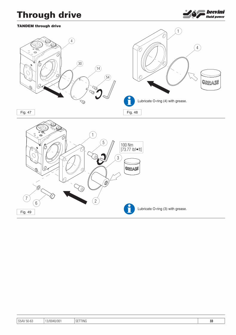
TANDEM through drive
Through drive
Lubricate O-ring (3) with grease.
Lubricate O-ring (4) with grease.

34 S5AV 50-63TESTING PROCEDURE 13/0040/001
CLS+TP testing procedure
1 - TESTING ON THE TEST RIGA) Mounting the pump on the test bench(see example of test layout)1. Place the coupling and flange on the test bench.2.Ensure the output shaft area is clean and without any oil trace, so
to spot any possible oil leakage after the test.3. Fit the coupling on the pump’s shaft.4. Mount the pump on the test bench, with the control upwards.5. Connect the suction hose and the pressure hose to the respective
flanges.6. Open the oil suction and fill the pump casing with oil.7. Set the desired rotation (CW / CCW).
B) Test procedure1. Adjust the stand-by pressure setting screw to about half of the
working stroke.2. Running-in at 500 rpm for 5 min., Half with low pressure and half
with pressure of 100 bar.3. Check / adjustment DISPLACEMENT MAX: 1500 rpm, 0 bar. With the flow control valve fully open, the pump will stroke to
maximum displacement. Unscrew the setting until the pump delivers the nominal flow for
the unit in question (see table). If there are limitations to the maximum displacement, flow will
read, nominally:
The screw needs to be then adjusted until it reads the nominal flow rate.
4. Lock the maximum displacement screw with its nut.5. Completely loosen the pressure cut-off setting screw. Check / adjustment MINIMUM DISPLACEMENT. 1500 rpm. Clo-
se the flow control valve on the pump delivery to Swivel it to mini-mum displacement. Caution: if in closing the valve.
Control the pressure increases excessively, unscrew minimum displacement setting screw!
Adjust the minimum displacement setting until it is observed an increase in the system pressure. From this point unscrew off 1/4 turn.
6. Lock the minimum displacement screw with its nut7. Check the flow with the pump unloaded at both the maximum and
minimum displacement set, by acting on the flow control valve, towards the displacement minimum and back to maximum mul-tiple times. Eventual errors must be corrected by repeating the procedure from step 3 or from step 6.
8. Close the flow control valve and, using the standby pressure set-ting screw, set the required value.
Setting range 18 to 35 bar. Lock the screw with its nut.
1500 [rpm] Vg [cm3/rev]1000
Q [l/min] =
9. Acting on the flow control valve, vary the opening of the same “in steps”, ie with variations almost instantaneous. The control should always maintain a constant Dp (pressure difference) be-fore and after of the flow control valve, without jamming or re-sponse delays.
10. Adjust the pressure cut-off setting screw close to its maximum pressure position, in order to ensure that the pump remains on its maximum displacement.
11. Clean the pump with appropriate solvent until eliminating traces of oil. This in order to identify possible loss and / or leakage during the pressure test.
12. Check FLOW under LOAD. 1500 rpm, 250 bar. The difference in flow rate of the pump must ensure that the
volumetric efficiency remains within the 93% - see calculation.
Q loaded/Q unloaded =0.93
Or check the values in the table. If there are limitations of maxi-mum displacement flow rate will be read, nominally:
Q loaded/Q unloaded =0.93
13. Increase system pressure up to a value higher than that provi-ded for the required cut-off valve control pressure.
Acting on the pressure cut-off valve adjusting screw, identify the point at which the controller begins to decrease the flow rate.
Lock the screw above with nut.14. Vary the pressure, increasing and decreasing many times, to
check the correct operation of the regulator. If necessary, repeat the procedure from step 12.15. Check for leaks and / or leakage. Then stop the pump.16. Fill out the test with the required data.
C) End test1. Open the lower drainage port on the pump casing and disconnect
the piloting line to discharge the oil.2. Remove the pump from the test bench.3. Check for leaks from the front cover and the shaft seal.
Table - control settings
Vgmax
[cm3/rev]
Vgmin
[cm3/rev]
Qmax (*)
[l/min]
Q250 (**)
[l/min]
Displacement variation for screw turn (ΔVg)
Screw
S5AV 50 49.7 0 74.5 70 3.80 c.c./giro M8
S5AV 63 63 0 95 89.3 4.90 c.c./giro M8
(*): 1500 rpm, 0 bar(**): 1500 rpm, 250 bar (minimum acceptable output flow rate)

35S5AV 50-63
LSY1
M1
M2
PG
M
S T1 T2R1 R2
Qmin
Qmax
Q maxX
TESTING PROCEDURE13/0040/001
CLS+TP testing procedureExample of test bench layout
Pressure gauge
Pressure gauge
2 - “ON THE FIELD” TESTIf the pump check and/or setting must be done with the pump alre-ady installed on the application, follow the procedure below. Check also layouts at page. 36.WARNING: during the procedure below moderate oil leakage from the pump will occur. Take actions to prevent contamination of the environment.
A) Minimum and Maximum displacement setting.1. The engine or motor must be STOPPED. If the pump is feeding
a proportional valve, check that all the spools of the sections are CLOSED. If the flow is controlled with a throttle valve, completely CLOSE it. Disconnect the LS line from the pump LS port, in such a way that the pressure in LS port is vented.
2. Adjust the Stand-by setting screw approximately midway of its setting field. Unscrew (turn counterclockwise) completely the cut-off pressure setting screw.
3. Start the engine or the motor. The pump swivels to the minimum displacement at stand-by pressure.
4. Adjust the minimum displacement setting screw until the pres-sure on the M port starts to increase. From said position, turn the minimum displacement setting screw counter-clockwise 180° (1/2 turn).
5. Lock the screw with locking nut and cap6. Open completely the proportional valve’s spools (or the throttle
valve) to reach the pump saturation flow.7. Adjust the maximum displacement setting screw to reach the re-
quired flow. WARNING: if this operation is dangerous or impossible to achieve, it is possible to set the maximum displacement screw following the values in the table below:
S5AV 50 S5AV 63
X measure
(mm)
21.5 (M8x55 screw)
21.5 (M8x55 screw)
Throttle valve

36 S5AV 50-63
M2S T1 T2R1 R2
M1PG
M
Qmin
Qmax
Y1
LSY1
M2S T1 T2R1 R2
M1PG
M
Qmin
Qmax
LSY1
TESTING PROCEDURE 13/0040/001
CLS+TP testing procedure8. Lock the screw with locking nut and cap.
B) Stand-by pressure setting1. The engine or motor must be STOPPED. If the pump is feeding
a proportional valve, check that all the spools of the sections are CLOSED. If the flow is controlled with a throttle valve, completely CLOSE it. Disconnect the LS line from the pump LS port, in such a way that the pressure in LS port is vented.
2. Start the engine or the motor.3. Adjust the stand-by pressure setting screw until the required va-
lue is reached. Optimum setting field is 18-35 bar. We do not recommend to exceed 38 bar.
4. Lock the screw with its locking nut.5. Stop the engine or moto.
C) Cut-off pressure setting1. The engine or motor must be STOPPED. If the pump is feeding
a proportional valve, check that all the spools of the sections are CLOSED. If the flow is controlled with a throttle valve, completely CLOSE it. Connect the LS port of the pump with the M port of the pump (we recommend a 1/4” hose).
2. Unscrew completely the cut-off valve setting screw (turn it counter-clockwise).
3. Start the engine or motor. WARNING: if the operation of point 2
has not been properly performed, it might be impossible to start the engine or motor.
4. Adjust the pressure cut-off setting screw until the required pres-sure is reached. Setting field 50-350 bar.
5. Lock the screw with its locking nut.6. Stop the engine or motor7. Restore all connections as per the original circuit layout.
D) Final checksPerform the machine setting and test as per the manufacturer’s spe-cifications.
Layout for “on the field” minimum displacement setting and Stand-by pressure setting
Pressuregauge
Pressure port must be closed
Layout for “on the field” cut-off pressure setting
Pressuregauge
Pressure port must be closed

37S5AV 50-63 TESTING PROCEDURE13/0040/001
1 - TESTING ON THE TEST RIGA) Mounting the pump on the test bench(see example of test layout)1. Place the coupling and flange on the test bench.2.Ensure the output shaft area is clean and without any oil trace, so
to spot any possible oil leakage after the test.3. Fit the coupling on the pump’s shaft.4. Mount the pump on the test bench, with the control upwards.5. Connect the suction hose and the pressure hose to the respective
flanges.6. Open the oil suction and fill the pump casing with oil.7. Set the desired rotation (CW / CCW).
B) Test procedure 1. Running-in at 500 rpm for 5 min., Half with low pressure and half
with pressure of 100 bar.2. Check / adjustment DISPLACEMENT MAX: 1500 rpm, 0 bar. Unscrew the setting until the pump delivers the nominal flow for
the unit in question (see table). If there are limitations to the ma-ximum displacement, flow will read, nominally:
The screw needs to be then adjusted until it reads the nominal flow rate.
3. Lock the maximum displacement screw with its nut.4. completely loosen the pressure cut-off setting screw. Check / adjustment MINIMUM DISPLACEMENT. 1500 rpm. Close the flow control valve on the pump delivery to swivel it to
minimum displacement. Caution: if in closing the valve control the pressure increases excessively, unscrew minimum displacement setting screw!
Adjust the minimum displacement setting until it is observed an increase in the system pressure. From this point unscrew off 1/4 turn.
5. Lock the minimum displacement screw with its nut.6. Check the flow with the pump at both the maximum and minimum
displacement set, by varying the operating pressure towards the displacement minimum and back to maximum multiple times. Eventual errors must be corrected by repeating the procedure.
7. Adjust the pressure cut-off setting screw close to its maximum pressure position, in order to ensure that the pump remains on its maximum displacement.
8. Clean the pump with appropriate solvent until eliminating traces of oil. This in order to identify possible loss and / or leakage du-ring the pressure test.
9. Check FLOW under LOAD. 1500 rpm, 250 bar. The difference in flow rate of the pump must ensure that the vo-
lumetric efficiency remains within the 93% - see calculation.
Q loaded/Q unloaded = 0.93
Or check the values in the table. If there are limitations of maxi-mum displacement flow rate will be read, nominally:
Q loaded/Q unloaded = 0.93
10. Increase system pressure up to a value higher than that provi-ded for the required cut-off valve control pressure.
Acting on the pressure cut-off valve adjusting screw, identify the point at which the controller begins to decrease the flow rate.
Lock the screw above with nut.11. Vary the pressure, increasing and decreasing many times, to
check the correct operation of the regulator. If necessary, repeat the procedure from step 12.12. Check for leaks and / or leakage. Then stop the pump.
1500 [rpm] Vg [cm3/rev]1000
Q [l/min] =
13. Fill out the test with the required data.
C) End test1. Open the lower drainage port on the pump casing and to dischar-
ge the oil.2. Remove the pump from the test bench.3. Check for leaks from the front cover and the shaft seal.
CTP testing procedure

38 S5AV 50-63TESTING PROCEDURE 13/0040/001
PI+PC testing procedure1 - TESTING ON THE TEST RIGA) Mounting the pump on the test bench1. Place the coupling and flange on the test bench.2.Ensure the output shaft area is clean and without any oil trace, so
to spot any possible oil leakage after the test.3. Fit the coupling on the pump’s shaft.4. Mount the pump on the test bench, with the control upwards.5. Connect the suction hose and the pressure hose to the respective
flanges.6. Open the oil suction and fill the pump casing with oil.7. Set the desired rotation (CW / CCW).
B) Testing procedure1. Check on orderform any eventual displacement limitation of the
pump.2. Running-in of the pump must be don e at 500 rpm and 0 bar for
approx. 2.5 min. and at 500 rpm and 100 bar far approx. 2.5 min.3. Verify/set MAXIMUM DISPLACEMENT: 1500 rpm, 0 bar. With
no piloting pressure, the pump is swivelled to the maximum di-splacement, thus the delivered flow rate must be the pump’s maximum nominai flow rate. Turn the maximum displacement adjustment screw until the nominai maximum flow rate is delive-red. lf any maximum displacement limitation have to be set, the nominai flow rate is:
The said screw must then be adjusted to obtain the calculated flow rate.
4. Lock the said adjustment screw with nut and locking nut (with their two washers).
5. Piloting pressure on PI port set ti 40 bar.6. Verify/set MINIMUM DISPLACEMENT: 1500 rpm, 0 bar. The
pump must not deliver any flow rate. Turn the minimum displa-cement setting screw until a zero flow rate is obtained. lf any displacement limitation have to be set, the nominai flow rate is:
The sai d screw must then be adjusted in order to obtain the cal-culated flow rate
7. Lock the minimum displacement adjustment screw with nut and locking nut (with their two washers).
8. By changing PI pressure between 0 and 40 bar, verify the maxi-mum and minimum displacementjust set. Any difference with the expected values must be corrected repeating the procedure from point 3. or point 7.
9 .Screw “Pressure Control” screw completely in.10. Using an appropriate solvent, clean the pump from any o il trace,
in order to check any oil leak during the following high pressure test.
11. Verifythe DRAINAGE FLOW RATE. 250 bar, 1500 rpm. The drainage flow rate is obtained from the difference between the nominal maximum flow rate at 0 bar and the actual flow rate at 250 bar.
12. Verify INPUT TORQUE: On order form is reported the contrai requested torque. Raise the pressure until the contral starting pressure is reached, keeping the pump at 1500 rpm, then read the input torque value. The said torque must not be greater than the said values in the control setting tables.
13 .Verifythe HYDRAULIC PILOTING STARTING AND ENDING PRESSURES. Fit the PI port pipe fitting on the top cap and connect the piloting pressure line. The40 bar boost pressure must act on port Y. Starting with a piloting pressure of 0 bar and with the pump at the minimum displacement, increase gradual-ly said pressure to find the hydraulic control starting (the flow
1500 [rpm] Vgmax [cm3/rev]1000
Qmax [l/min] =
1500 [rpm] Vgmin [cm3/rev]1000
Qmin [l/min] =
rate starts to increase ). Starting with a piloting pressure abo-ve 40 bar, decrease said pressure to find the hydraulic control ending pressure (the flow rate starts to decrease). Verify the control stability with intermediate hydraulic piloting pressures. Verify that the control can always reach the pre-set maximum and minimum displacements. The hydraulic piloting starting and ending pressures must be conveniently recorded on test form.
14. IMPORTANT: Should the pump function with a working pressu-re of less than 40 bar, the retum from Vgmax to Vgmin might be difficult or impossible, even with the 40 bar control boost pressu-re on top cap. lf, in such a case, the pump takes more than 5-10 sec. to restore from Vgmax to Vgmin or, even worse, it doesn’t restore, try to operate several complete displacement variation cycles (Vgmax to Vgmin and vice versa) with higher working pressure, then repeat the low pressure test. lf, after all, the pro-blem is still present, the pump must be overhauled.
15. Increase the working pressure until the requested pressure cut-off value is reached. Acting on the cutoff pressure setting screw (control CTP), turn it until the flow rate start to decrease.
Lock the said screw into position with nut.16. Increase and decrease the working pressure several times, in
order to check the control functioning. 17. Verify the eventual presence of any oil leak. Stop the pump.18. Fill the pump test form with the required data.
C) End test1. Open the lower drainage port on the pump casing and to dischar-
ge the oil.2. Remove the pump from the test bench.3. Verify the eventual oil leak from the front cover and the shaft seal.

39S5AV 50-63 TESTING PROCEDURE13/0040/001
1 - TESTING ON THE TEST RIGA) Mounting the pump on the test bench1. Place the coupling and flange on the test bench.2.Ensure the output shaft area is clean and without any oil trace, so
to spot any possible oil leakage after the test.3. Fit the coupling on the pump’s shaft.4. Mount the pump on the test bench, with the control upwards.5. Connect the suction hose and the pressure hose to the respective
flanges.6. Open the oil suction and fill the pump casing with oil.7. Set the desired rotation (CW / CCW).
B) Testing procedure1. Check on orderform any eventual displacement limitation of the
pump.2. Running-in of the pump must be don e at 500 rpm and 0 bar for
approx. 2.5 min. and at 500 rpm and 100 bar far approx. 2.5 min.3. Verify/set MAXIMUM DISPLACEMENT: 1500 rpm, 0 bar. With
no piloting pressure, the pump is swivelled to the maximum di-splacement, thus the delivered flow rate must be the pump’s maximum nominai flow rate. Turn the maximum displacement adjustment screw until the nominai maximum flow rate is delive-red. lf any maximum displacement limitation have to be set, the nominai flow rate is:
The said screw must then be adjusted to obtain the calculated flow rate.
4. Lock the said adjustment screw with nut and locking nut (with their two washers).
5. Piloting pressure on PI port set ti 40 bar.6. Verify/set MINIMUM DISPLACEMENT: 1500 rpm, 0 bar. The
pump must not deliver any flow rate. Turn the minimum displa-cement setting screw until a zero flow rate is obtained. lf any displacement limitation have to be set, the nominai flow rate is:
The sai d screw must then be adjusted in order to obtain the cal-culated flow rate
7. Lock the minimum displacement adjustment screw with nut and locking nut (with their two washers).
8. By changing PI pressure between 0 and 40 bar, verify the maxi-mum and minimum displacementjust set. Any difference with the expected values must be corrected repeating the procedure from point 3. or point 7.
9 .Screw “Pressure Control” screw completely in.10. Screw in the contrai setting spring adjustment screw until close
to the said spring’s maximum preload, in order to keep the pump at the maximum displacement during the high pressure tests.
11 .Using an appropriate solvent, clean the pump from any oil trace, in order to check any oil leak during the following high pressure test.
12.Verify the DRAINAGE FLOW RATE. 250 bar, 1500 rpm. The drainage flow rate is obtained from the difference between the nominai maximum flow rate at 0 bar and the actual flow rate at 250 bar.
13. Tuming the power control screw, find out the starting point of the control (when the control starts to swivel towards the mini-mum displacement, thus reducing the flow rate). Lock the pilot pushing screw into position with its locking screw.
14. Verify INPUT TORQUE: On order form is reported the contrai requested torque. Raise the pressure until the contral starting pressure is reached, keeping the pump at 1500 rpm, then read the input torque value. The said torque must not be greater than
1500 [rpm] Vgmax [cm3/rev]1000
Qmax [l/min] =
1500 [rpm] Vgmin [cm3/rev]1000
Qmin [l/min] =
the said values in the control setting tables.15 .Verifythe HYDRAULIC PILOTING STARTING AND ENDING
PRESSURES. Fit the PI port pipe fitting on the top cap and connect the piloting pressure line. The40 bar boost pressure must act on port Y. Starting with a piloting pressure of 0 bar and with the pump at the minimum displacement, increase gradual-ly said pressure to find the hydraulic control starting (the flow rate starts to increase ). Starting with a piloting pressure abo-ve 40 bar, decrease said pressure to find the hydraulic control ending pressure (the flow rate starts to decrease). Verify the control stability with intermediate hydraulic piloting pressures. Verify that the control can always reach the pre-set maximum and minimum displacements. The hydraulic piloting starting and ending pressures must be conveniently recorded on test form.
16. IMPORTANT: Should the pump function with a working pressu-re of less than 40 bar, the retum from Vgmax to Vgmin might be difficult or impossible, even with the 40 bar control boost pressu-re on top cap. lf, in such a case, the pump takes more than 5-10 sec. to restore from Vgmax to Vgmin or, even worse, it doesn’t restore, try to operate several complete displacement variation cycles (Vgmax to Vgmin and vice versa) with higher working pressure, then repeat the low pressure test. lf, after all, the pro-blem is still present, the pump must be overhauled.
17. Increase the working pressure until the requested pressure cut-off value is reached. Acting on the cutoff pressure setting screw (control Power Control), turn it until the flow rate start to decre-ase.
Lock the said screw into position with nut.18. Increase and decrease the working pressure several times, in
order to check the control functioning. 19. Verify the eventual presence of any oil leak. Stop the pump.20. Fill the pump test form with the required data.
C) End test1. Open the lower drainage port on the pump casing and to dischar-
ge the oil.2. Remove the pump from the test bench.3. Verify the eventual oil leak from the front cover and the shaft seal.
NC+PI+PC testing procedure

40 S5AV 50-63TESTING PROCEDURE 13/0040/001
NC+PC testing procedure1 - TESTING ON THE TEST RIGA) Mounting the pump on the test bench1. Place the coupling and flange on the test bench.2.Ensure the output shaft area is clean and without any oil trace, so
to spot any possible oil leakage after the test.3. Fit the coupling on the pump’s shaft.4. Mount the pump on the test bench, with the control upwards.5. Connect the suction hose and the pressure hose to the respective
flanges.6. Open the oil suction and fill the pump casing with oil.7. Set the desired rotation (CW / CCW).
B) Testing procedure1. Running-in at 500 rpm for 5 min., half with low pressure and half
with pressure of 100 bar.2. Unscrew the pressure valve control and the power control valve
screws almost completely.3. Close the flow control valve on the pump delivery to swivel it to
minimum displacement. Caution: if in closing the valve control the pressure increases excessively, unscrew minimum displacement setting screw! Adjust the minimum displacement setting until it is observed an increase in the system pressure. From this point unscrew off 1/4 turn. If there are limitations to the maximum di-splacement, flow will read, nominally:
The screw needs to be then adjusted until it reads the nominal flow rate.
4. Lock the minimum displacement screw with its nut. 5. Check / adjustment DISPLACEMENT MAX: 1500 rpm, 0 bar. With the flow control valve fully open, the pump will stroke to ma-
ximum displacement. Unscrew the displacement setting until the pump delivers the nominal flow for the unit in question. If there are limitations to the maximum displacement, flow will read, no-minally:
The screw needs to be then adjusted until it reads the nominal flow rate.
6. Lock the maximum displacement screw with its nut.7. Check the flow with the pump unloaded at both the maximum and
minimum displacement set, by acting on the flow control valve, towards the displacement minimum and back to maximum mul-tiple times. Errors must be corrected by repeating the procedure from step 2.
8. Clean the pump with appropriate solvent until eliminating traces of oil. This in order to identify possible loss and / or leakage du-ring the pressure test.
9. Adjust the pressure cut-off setting screw and the power setting screw close to the maximum position.
Check FLOW under LOAD. 1500 rpm, 250 bar. The difference in flow rate of the pump must ensure that the vo-
lumetric efficiency remains within the 93% - see calculation.
Q loaded/Q unloaded = 0.93
Or check the values in the table. If there are limitations of maxi-mum displacement flow rate will be read, nominally:
Q loaded/Q unloaded = 0.93
10. Check / adjustment pressure setting (PC). Increase system pressure up to a value higher than that provi-
ded for the required cut-off valve control pressure.
1500 [rpm] Vgmax [cm3/rev]1000
Qmax [l/min] =
11. Acting on the pressure cut-off valve adjusting screw, identify the point at which the controller begins to decrease the flow rate. Lock the screw above with nut.
12. Vary the pressure, increasing and decreasing many times, to check the correct operation of the regulator.
13. Check / adjustment constant power control (NC). Set the pressure of the setting operation (P0) which is expected
for the power value required calibration to 1500 rpm::
14. Acting on the NC control setting screw, identify the point at which the controller begins to decrease the displacement (the flow rate begins to decrease). Also check through reading the value of absorbed power.
15. Check of absorption of torque to the variation of the pressu-re: starting from pressure value corresponding to the start adjustment you may experience the values of flow rate, tor-que and power absorbed, to vary the operating pressure. This should be checked many times and by increasing or decrea-sing, the “stair step”, the operating pressure, for identify any problems of repeatability of the operation.
16. Lock the screw above with nut.17. Check / adjustment pressure setting (PC). Increase system pressure up to a value higher than that provi-
ded for the required cut-off valve control pressure. Acting on the pressure cut-off valve adjusting screw, identify the
point at which the controller begins to decrease the flow rate. Lock the screw above with nut.
WARNING: During this adjustment could occur an intervention con-troller NC (before reaching the set pressure of the PC control the pump could limit, but do not reset the flow rate) which ho-wever does not compromises the calibration of the controller.
18. Vary the pressure, increasing and decreasing many times, to check the correct operation of the regulator.
If necessary, repeat the procedure.19. Check for leaks and / or leakage. Then stop the pump.20. Fill out the test with the required data.
C) End test1. Open the lower drainage port on the pump casing and to dischar-
ge the oil.2. Remove the pump from the test bench.3. Verify the eventual oil leak from the front cover and the shaft seal.
1500 [rpm] Vgmin [cm3/rev]1000
Qmin [l/min] =
N [KW] 400 Vgmax [cm3/rev]
P0 [bar] =

41S5AV 50-63 TESTING PROCEDURE13/0040/001
1500 [rpm] Vgmax [cm3/rev]1000
Qmax [l/min] =
N [KW] 400 Vgmax [cm3/rev]
P0 [bar] =
NC+LS+TP3 testing procedure1 - TESTING ON THE TEST RIGA) Mounting the pump on the test bench1. Place the coupling and flange on the test bench.2.Ensure the output shaft area is clean and without any oil trace, so
to spot any possible oil leakage after the test.3. Fit the coupling on the pump’s shaft.4. Mount the pump on the test bench, with the control upwards.5. Connect the suction hose and the pressure hose to the respective
flanges.6. Open the oil suction and fill the pump casing with oil.7. Set the desired rotation (CW / CCW).
B) Testing procedure1. Adjust the stand-by pressure setting screw to about half of the
working stroke, and turn on the screws of the pressure valve con-trol and the power control valve almost completely.
2. Running-in at 500 rpm for 5 min., half with low pressure and half with pressure of 100 bar.
3. Check / adjustment DISPLACEMENT MAX: 1500 rpm, 0 bar. With the flow control valve fully open, the pump will stroke to
maximum displacement. Unscrew the setting until the pump delivers the nominal flow for
the unit in question (see table). If there are limitations to the ma-ximum displacement, flow will read, nominally:
The screw needs to be then adjusted until it reads the nominal flow rate.
4. Lock the maximum displacement screw with its nut.5. completely loosen the pressure cut-off setting screw. Check / adjustment MINIMUM DISPLACEMENT. 1500 rpm. Close the flow control valve on the pump delivery to swivel it to
minimum displacement. Caution: if in closing the valve control the pressure increases excessively, unscrew minimum displacement setting screw!
Adjust the minimum displacement setting until it is observed an increase in the system pressure. From this point unscrew off 1/4 turn.
6. Lock the minimum displacement screw with its nut.7. Check the flow with the pump unloaded at both the maximum and
minimum displacement set, by acting on the flow control valve, towards the displacement minimum and back to maximum mul-tiple times.
Eventual errors must be corrected by repeating the procedure from step 3 or from step 6.
8. Close the flow control valve and, using the standby pressure set-ting screw, set the required value. Setting range 18 to 35 bar. Lock the screw with its nut.
9. Acting on the flow control valve, vary the opening of the same “in steps”, ie with variations almost instantaneous.
The control should always maintain a constant Dp (pressure dif-ference) before and after of the flow control valve, without jam-ming or response delays.
10. Adjust the pressure cut-off setting screw close to its maximum pressure position, in order to ensure that the pump remains on its maximum displacement.
11. Clean the pump with appropriate solvent until eliminating traces of oil. This in order to identify possible loss and / or leakage during the pressure test.
12. Check FLOW under LOAD. 1500 rpm, 250 bar. The difference in flow rate of the pump must ensure that the
volumetric efficiency remains within the 93% - see calculation.
Q loaded/Q unloaded = 0.93
13. Check / adjustment constant power control (NC). Set the pressure of the setting operation (P0) which is expected
for the power value required calibration to 1500 rpm:
14. Acting on the NC control setting screw, identify the point at which the controller begins to decrease the displacement (the flow rate begins to decrease). Also check through reading the value of absorbed power.
15. Check of absorption of torque to the variation of the pressu-re: starting from pressure value corresponding to the start adjustment you may experience the values of flow rate, torque and power absorbed, to vary the operating pressure.
This should be checked many times and by increasing or decre-asing, the “stair step”, the operating pressure, for identify any problems of repeatability of the operation.
16. Lock the screw above with nut.17. CHeck / adjustment pressure cut-off (TP). Increase system pressure up to a value higher than that provi-
ded for the required cut-off valve control pressure. Acting on the pressure cut-off valve adjusting screw, identify the
point at which the controller begins to decrease the flow rate. Lock the screw above with nut.WARNING: During this adjustment could occur an intervention con-
troller NC (before reaching the set pressure of the PC control the pump could limit, but do not reset the flow rate) which ho-wever does not compromises the calibration of the controller.
18. Vary the pressure, increasing and decreasing many times, to check the correct operation of the regulator.
If necessary, repeat the procedure from step 12.19. Check for leaks and / or leakage. Then stop the pump.20. Fill out the test with the required data.
C) End test1. Open the lower drainage port on the pump casing and to dischar-
ge the oil.2. Remove the pump from the test bench.3. Check for leaks from the front cover and the shaft seal.

42 S5AV 50-63STORAGE AND DEMOLITION 13/0040/001
Storage and demolitionStorage
Demolition
Do not dispose outdoors but hand the motors (or pumps) over tospecialised waste collection centres.
Fill with oil all the ports and the casingS and apply protective plastic caps on the open parts of the motor (or pump) to avoid the entry of foreign bodies.Store in a dry place and protect from dust or rain. (eg: plastic bag).

43S5AV 50-63 13/0040/001
Brevini Fluid Power S.p.a.Via Natta N° 1
42124 Reggio Emilia (ITALY)Tel. +39-0522-748700Fax.+39-0522-748750
e-mail: [email protected] web-site: www.brevinifluidpower.com