PUMP OWNERS MANUAL CONDE SUPER SERIES …...PUMP OWNERS MANUAL CONDE SUPER SERIES PUMPS Performance...
17
PUMP OWNERS MANUAL CONDE SUPER SERIES PUMPS Performance by Design Westmoor, Ltd. P.O. Box 99, 906 West Hamilton Avenue Sherrill, New York 13461 Phone: 800-367-0972 Fax: 315-363-0193 E-mail [email protected]
Transcript of PUMP OWNERS MANUAL CONDE SUPER SERIES …...PUMP OWNERS MANUAL CONDE SUPER SERIES PUMPS Performance...
PUMP OWNERS MANUAL
CONDE SUPER SERIES PUMPS
Performance by Design
Westmoor, Ltd.
P.O. Box 99, 906 West Hamilton Avenue Sherrill, New York 13461
Phone: 800-367-0972 Fax: 315-363-0193 E-mail [email protected]
INITIAL START UP OF SUPER SERIES PUMPS Congratulations on your purchase of a Conde Super Series pump. You have selected the finest and most innovative vacuum pump available. Conde designs and builds pumps for long life, durability and ease of use.
SAFETY INFORMATION WARNING: The vacuum pump has rotating parts. Keep guards in place. Never operate the pump
with the guards removed.
WARNING: The vacuum pump may reach temperatures above 200 degrees F during extended or
severe duty operation. Allow to cool before servicing.
CAUTION: Never operate without oil. Failure to properly lubricate the pump will cause premature
failure.
CAUTION: The pump will discharge oil from the exhaust port. Connect the exhaust port to an ade-
quate oil recovery system.
IMPORTANT Vacuum relief valves have NOT been pre-set. (These should both be adjusted after the pump is installed) To adjust vacuum relief valve 1) If the pump is equipped with the slide valve diverter valve, pull the handle out to engage in the vacuum mode. 2) Close all openings in the vacuum system. 3) Start pump. 4) Loosen jam lock nut on top of the relief valve. 5) Under the jam nut is the adjustment nut. Turn nut clockwise to increase vacuum, turn counter-clockwise to decrease vacuum. 6) After desired vacuum is reached, re-tighten jam lock nut.
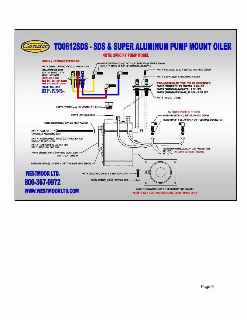
CAUTION: DO NOT EXCEED 20” HG FOR CONTINUOUS OPERATION CONDE WICK OILING SYSTEM All Conde Super Series pumps are now equipped with the trouble free and adjustment free Conde Wick Oiling System. The Conde Wick system has been engineered to provide constant oiling to your vacuum pump under all operating conditions. There is never any need for adjustment of any kind. No more fool-ing with tricky drip oilers. Before operating your pump, fill the oil reservoir with a premium quality 10W-30 grade high detergent
synthetic motor oil. After taking delivery of your pump, make sure that the oil reser-voir is filled. Pumps are not shipped with oil in the reservoir. Fill the tank until it is just
below The level of the tank jets in the inside of the reservoir. All tank oilers are equipped with a sight glass to determine the oil level inside the tank.
Page 1
OIL RECOMMENDATIONS Use high detergent 10W-30 motor oil only. Synthetic oil is highly recommended and will extend the life of your pump. Using the proper type and weight oil is essential for long life and trouble free opera-
tion. Using the wrong oil or dirty oil can cause loss of vacuum or pump failure. Never run the pump without oil in the tank oiler. Running the pump without oil in the reservoir will cause pump failure! Changing the oil is not necessary since the oil is discharged from the pump and should be properly dis-posed of. Check the oil level daily or every 8 hours of operation. Any oil catch devises used with the pump unit should be periodically drained to avoid oil being blown out the exhaust. This used oil should not be re-used.
GENERAL MAINTENANCE If pump is pulley driven, adjust belt to 1/2” of free play at center of the pulleys. Make the first adjustment after the first 24 hours of operation. Make any additional adjustments when necessary. Generally, the only maintenance required on the Super vacuum pump, is to maintain oil in the oil reser-voir. It is imperative that the pump is always getting the proper supply of oil. Periodically or at least once a week, visually look at the window in the oil dripper, or the wick oiler oil tube, to make sure the proper amount of oil is being drawn into the pump. If no oil is being sucked into the pump, immediately turn the pump off. Please refer to the trouble shooting section of this manual for more information on correcting the problem. The pump should be isolated from any contaminates so that no foreign substance or moisture can enter the pump. However, if anything is inadvertently sucked into the pump, the pump should be flushed im-mediately to remove all contaminates. If it is not immediately flushed, rust can form inside the pump which can, in turn, cause pump failure.
FLUSHING INSTRUCTIONS It may be necessary to flush your pump to remove and gum or varnish buildup inside the pump that causes the vanes to stick inside their slots. This is a simple maintenance operation and should be the first step when troubleshooting a loss of vacuum in a system. Before starting, be sure the exhaust from the oil catching devise (oil catch muffler) is directed away from the motor or engine and any other hot surfaces). Open the flush valve on Super HD models and insert a tube into it. On vacuum only models, detach one of the oil tubes from its connection to the oil tank. Use kerosene or diesel fuel for flushing. NEVER USE GASOLINE OR OTHER HIGHLY FLAMMABLE LIQUID FOR FLUSHING. While the pump is running under vacuum (slide valve in out position on HD models), simply insert the other end of the tube into the cleaning fluid and allow the pump to draw the fluid in. If there is no vacu-um present, disconnect the air hose from the top of the slide valve on HD models, or disconnect the in-take hose to the tank on vacuum only models, and pour a couple of ounces of cleaning fluid in. Alter-nately, let air into the tube in the cleaning solution. It can take up to a quart of cleaning solution to flush out a pump. When flushing is complete, draw about five ounces of oil into the pump in the same man-ner. This completes the flushing process. Remove the tube from the flush valve and close it on the HD models, or reattach the oil tube to the tank oiler on vacuum only models. Finally, reconnect any hoses that were disconnected. On badly gummed up pumps it may be necessary to pour a large quantity of cleaning fluid into the pump (enough to fill the entire pump) and let it sit over night. Be careful to drain as much of the cleaning fluid as possible out of the pump before attempting to turn the pump on.
Page 2
STORAGE OF VACUUM PUMPS Disconnect air lines and pump fittings from the intake and exhaust ports of the air pump. Then open the flush valve and pour about five ounces of oil into it. Turn the rotor shaft by hand a few times to coat the inside of the pump housing with oil. Close the flush valve and fill the oil tank with oil. Plug the pump ports with commercial pipe plugs or the plastic plugs that were supplied with the unit. Coat the shaft with a small amount of grease or oil to prevent rust buildup during storage. Store the air pump in a cool, dry place. IMPORTANT – When RE-STARTING the air pump after storage, turn the pump over by hand to be sure the shaft and rotor assembly spins freely within the pump housing. If any binding or restriction is felt, the pump must be taken apart and cleaned.
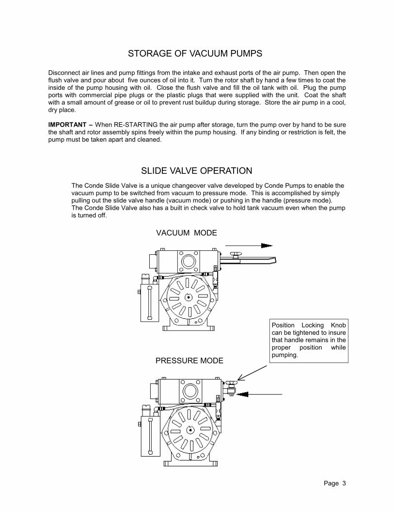
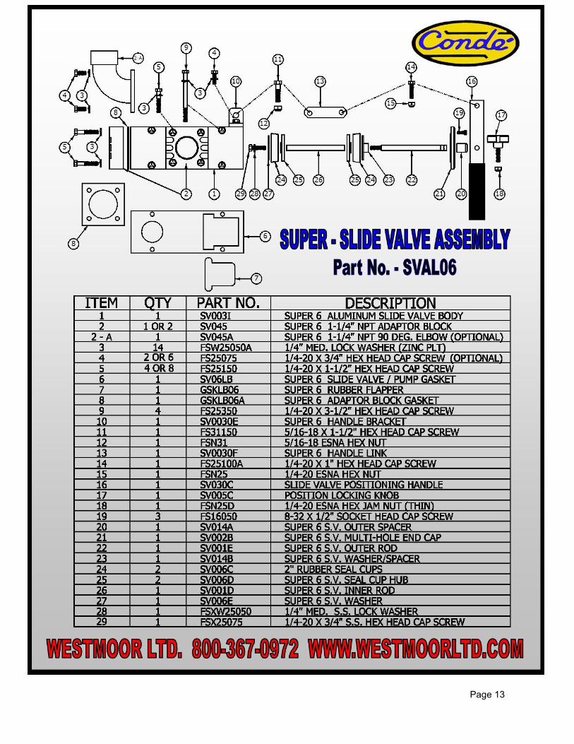
SLIDE VALVE OPERATION
Page 3
VACUUM MODE
PRESSURE MODE
The Conde Slide Valve is a unique changeover valve developed by Conde Pumps to enable the vacuum pump to be switched from vacuum to pressure mode. This is accomplished by simply pulling out the slide valve handle (vacuum mode) or pushing in the handle (pressure mode). The Conde Slide Valve also has a built in check valve to hold tank vacuum even when the pump is turned off.
Position Locking Knob can be tightened to insure that handle remains in the proper position while pumping.

CONDE SUPER SERIES DISASSEMBLY & ASSEMBLY TOOLS REQUIRED: Flathead Screwdriver 1/2” Wrench 9/16” Wrench Hammer Rubber Mallet Fine File Tool Kit (Optional) Includes: Shaft Collar, Endplate Removal Bolts, Bearing Installation Tool.
Disassembly 1) If pump is HD model, remove the slide valve first by: a) Detach the oil lines from the pump to the oil reservoir. b) Remove the four bolts from the top to the slide valve and lift off. c) Remove gasket under the Slide Valve. 2) If pump is HD Super #12, the Slide Valve and Manifold can be removed together by: a) Detach the oil lines from the pump to the oil reservoir. b) Remove the six bolts holding the manifold to the pump housing and lift off the manifold and slide valve. c) Remove the two gaskets underneath the manifold. 3) Remove the tank oiler (if attached to the pump). 4) Loosen the Allen set screws and remove the cooling fans. 5) Remove all endplate hex screws and all twelve bearing cover screws. 6) Remove both bearing covers, and all shims. 7) Slide the shaft collar (from tool kit) over shaft and tighten screw very securely. Use the fan set hole to help collar from sliding. 8) Grease the ends of the bolts (from tool kit) and screw them into the three threaded holes located in the endplate on the opposite side of the pump that the collar is on. Turn the bolts alternating with no more than one turn at a time until endplate slides off the rotor shaft. 9) Remove the bearing and oil seal from the endplate. 10) Put the plate just removed back in place without bearing, then slide the collar over the shaft and tighten very securely using the fan set hole. 11) Remove the opposite endplate using the 3 bolts as previously done. 12) Remove the bearing and oil seal from the endplate. 13) Remove the rotor and vanes from the rotor.
Pump rotation can be determined by viewing the disassembled rotor.
CW ROTATION CCW ROTATION
Page 4
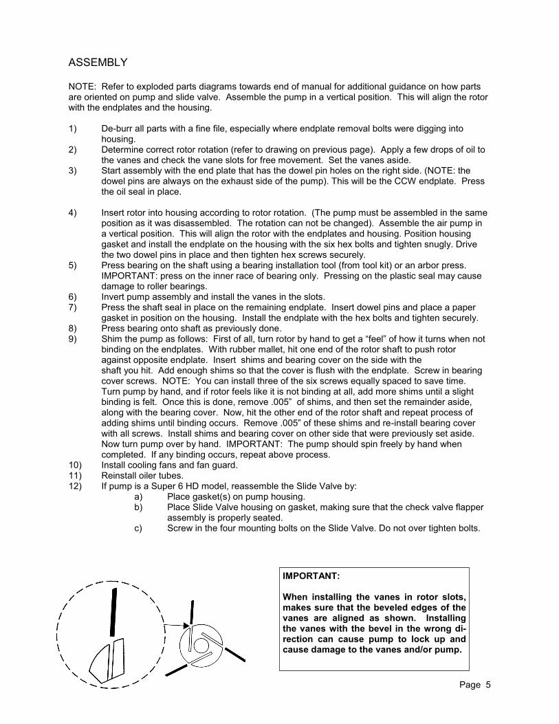
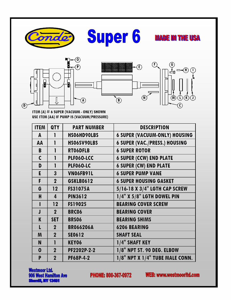
ASSEMBLY NOTE: Refer to exploded parts diagrams towards end of manual for additional guidance on how parts are oriented on pump and slide valve. Assemble the pump in a vertical position. This will align the rotor with the endplates and the housing. 1) De-burr all parts with a fine file, especially where endplate removal bolts were digging into housing. 2) Determine correct rotor rotation (refer to drawing on previous page). Apply a few drops of oil to the vanes and check the vane slots for free movement. Set the vanes aside. 3) Start assembly with the end plate that has the dowel pin holes on the right side. (NOTE: the dowel pins are always on the exhaust side of the pump). This will be the CCW endplate. Press the oil seal in place. 4) Insert rotor into housing according to rotor rotation. (The pump must be assembled in the same position as it was disassembled. The rotation can not be changed). Assemble the air pump in a vertical position. This will align the rotor with the endplates and housing. Position housing gasket and install the endplate on the housing with the six hex bolts and tighten snugly. Drive the two dowel pins in place and then tighten hex screws securely. 5) Press bearing on the shaft using a bearing installation tool (from tool kit) or an arbor press. IMPORTANT: press on the inner race of bearing only. Pressing on the plastic seal may cause damage to roller bearings. 6) Invert pump assembly and install the vanes in the slots. 7) Press the shaft seal in place on the remaining endplate. Insert dowel pins and place a paper gasket in position on the housing. Install the endplate with the hex bolts and tighten securely. 8) Press bearing onto shaft as previously done. 9) Shim the pump as follows: First of all, turn rotor by hand to get a “feel” of how it turns when not binding on the endplates. With rubber mallet, hit one end of the rotor shaft to push rotor against opposite endplate. Insert shims and bearing cover on the side with the shaft you hit. Add enough shims so that the cover is flush with the endplate. Screw in bearing cover screws. NOTE: You can install three of the six screws equally spaced to save time. Turn pump by hand, and if rotor feels like it is not binding at all, add more shims until a slight binding is felt. Once this is done, remove .005” of shims, and then set the remainder aside, along with the bearing cover. Now, hit the other end of the rotor shaft and repeat process of adding shims until binding occurs. Remove .005” of these shims and re-install bearing cover with all screws. Install shims and bearing cover on other side that were previously set aside. Now turn pump over by hand. IMPORTANT: The pump should spin freely by hand when completed. If any binding occurs, repeat above process. 10) Install cooling fans and fan guard. 11) Reinstall oiler tubes. 12) If pump is a Super 6 HD model, reassemble the Slide Valve by: a) Place gasket(s) on pump housing. b) Place Slide Valve housing on gasket, making sure that the check valve flapper assembly is properly seated. c) Screw in the four mounting bolts on the Slide Valve. Do not over tighten bolts.
Page 5
IMPORTANT: When installing the vanes in rotor slots, makes sure that the beveled edges of the vanes are aligned as shown. Installing the vanes with the bevel in the wrong di-rection can cause pump to lock up and cause damage to the vanes and/or pump.
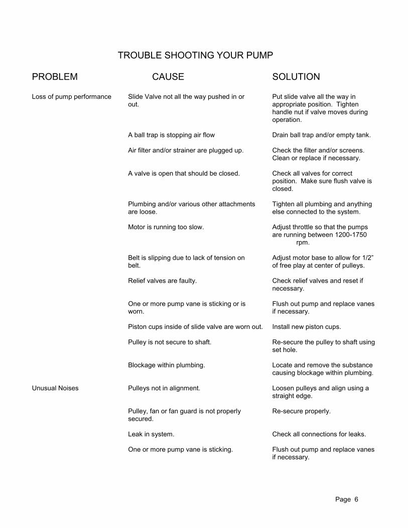
TROUBLE SHOOTING YOUR PUMP PROBLEM CAUSE SOLUTION Loss of pump performance Slide Valve not all the way pushed in or Put slide valve all the way in out. appropriate position. Tighten handle nut if valve moves during operation. A ball trap is stopping air flow Drain ball trap and/or empty tank. Air filter and/or strainer are plugged up. Check the filter and/or screens. Clean or replace if necessary. A valve is open that should be closed. Check all valves for correct position. Make sure flush valve is closed. Plumbing and/or various other attachments Tighten all plumbing and anything are loose. else connected to the system. Motor is running too slow. Adjust throttle so that the pumps are running between 1200-1750 rpm. Belt is slipping due to lack of tension on Adjust motor base to allow for 1/2” belt. of free play at center of pulleys. Relief valves are faulty. Check relief valves and reset if necessary. One or more pump vane is sticking or is Flush out pump and replace vanes worn. if necessary. Piston cups inside of slide valve are worn out. Install new piston cups. Pulley is not secure to shaft. Re-secure the pulley to shaft using set hole. Blockage within plumbing. Locate and remove the substance causing blockage within plumbing. Unusual Noises Pulleys not in alignment. Loosen pulleys and align using a straight edge. Pulley, fan or fan guard is not properly Re-secure properly. secured. Leak in system. Check all connections for leaks. One or more pump vane is sticking. Flush out pump and replace vanes if necessary.
Page 6
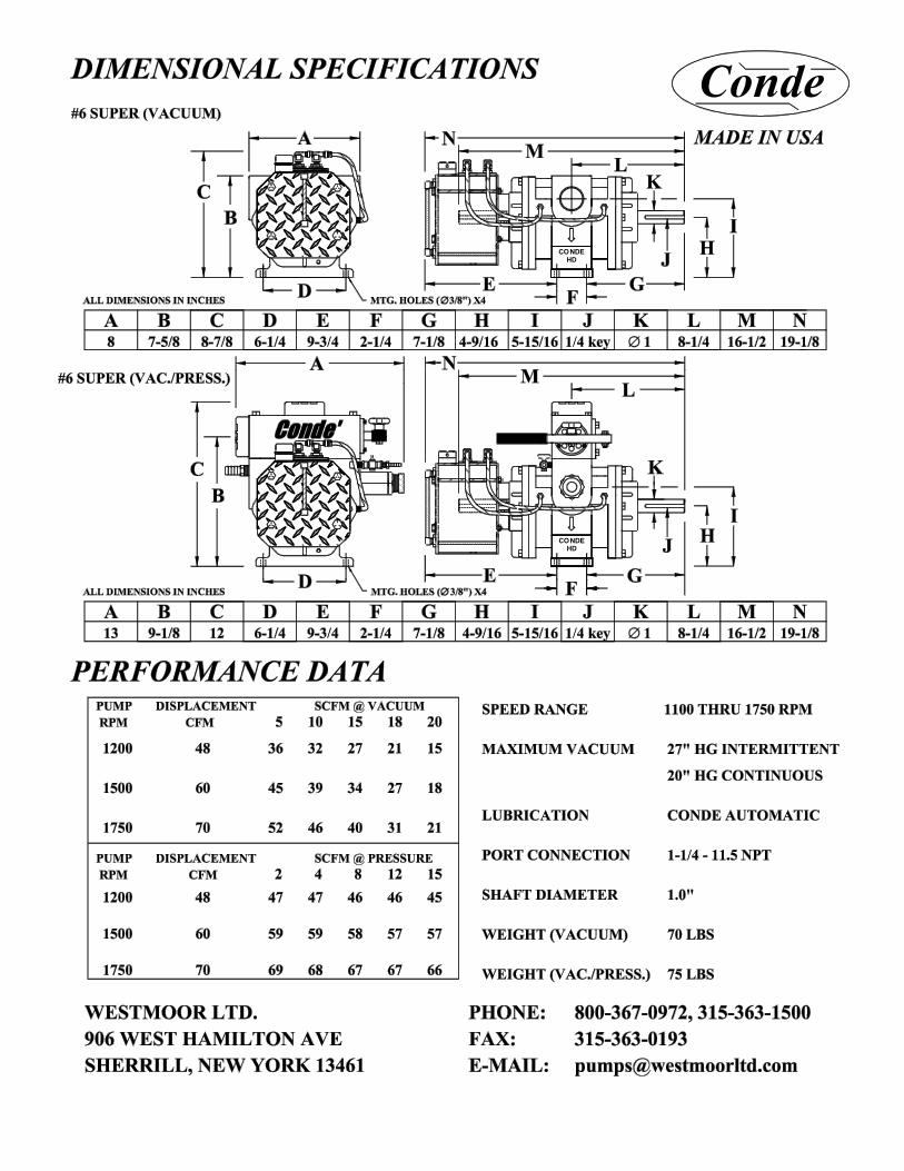
PUMP DRIVE CONSIDERATIONS Conde Super Series pumps can be belt driven or direct driven with couplings from gasoline or diesel engines, electric motors, PTO drives, or hydraulic motors. BELT DRIVE SYSTEMS Pulley combinations should be chosen so that pumps run within the specified speed range. All Conde Super Models are made to operate between 1000 and 1750 rpm. Pulleys should be specified that have adequate “belt wrap” so that maximum contact of belt to pulley can be achieved and minimize the chance of damage to the pump by over-tightening the belt(s). Please contact Westmoor, Ltd. For infor-mation on proper pulley combinations and belt sizes for your Super model and application. Always leave about 1/2” of belt play when adjusting the belt. Over-tightening the belt can damage the pump and not enough tension can cause belt slip and loss of pump performance. DIRECT DRIVE COUPLINGS We recommend Lovejoy type couplings with a flexible rubber “spider” between the pump mounted flange and the motor mounted flange. Couplings must be carefully aligned per the manufacturer’s speci-fications. A small straight edge and set of feeler gauges should be used to insure that the coupling is aligned properly. Call Westmoor, Ltd. to determine which model coupling is correct for your pump and application. UNDER THE HOOD Super Series pumps are available in under-the-hood versions complete with electric clutches. These pumps are designed to be driven off a truck engine. Conde Super under-the-hood pumps are available with clutches that accept either v-belt or poly-groove serpentine belt drives. The poly-groove clutches are availble in either six or eight groove versions. Conde Super clutch pumps are also available with remote oilers Due to the many different models and model years of trucks that could be capable of under-the-hood pump installation, Westmoor, Ltd. can not offer mounting brackets for various trucks. It is up to the pump installer to determine how the pump is to be installed. General guidelines for proper belt tensioning should be observed.
Page 7
START
OFF ON START
CONDE
HONDA
1
2
3
4 5
67
8
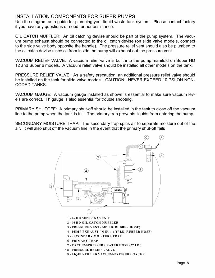
1 - #6 HD SUPER GAS UNIT
2 - #6 HD OIL CATCH MUFFLER
3 - PRESSURE VENT (5/8" I.D. RUBBER HOSE)
4 - PUMP EXHAUST ( MIN. 1-1/4" I.D. RUBBER HOSE)
5 - SECONDARY MOISTURE TRAP
6 - PRIMARY TRAP
7 - VACUUM/PRESSURE RATED HOSE (2" I.D.)
8 - PRESSURE RELIEF VALVE
9
9 - LIQUID FILLED VACUUM-PRESSURE GAUGE
*
DRAIN
INSTALLATION COMPONENTS FOR SUPER PUMPS Use the diagram as a guide for plumbing your liquid waste tank system. Please contact factory if you have any questions or need further assistance. OIL CATCH MUFFLER: An oil catching devise should be part of the pump system. The vacu-um pump exhaust should be connected to the oil catch devise (on slide valve models, connect to the side valve body opposite the handle). The pressure relief vent should also be plumbed to the oil catch devise since oil from inside the pump will exhaust out the pressure vent. VACUUM RELIEF VALVE: A vacuum relief valve is built into the pump manifold on Super HD 12 and Super 6 models. A vacuum relief valve should be installed all other models on the tank. PRESSURE RELIEF VALVE: As a safety precaution, an additional pressure relief valve should be installed on the tank for slide valve models. CAUTION: NEVER EXCEED 10 PSI ON NON-CODED TANKS. VACUUM GAUGE: A vacuum gauge installed as shown is essential to make sure vacuum lev-els are correct. Th gauge is also essential for trouble shooting. PRIMARY SHUTOFF: A primary shut-off should be installed in the tank to close off the vacuum line to the pump when the tank is full. The primary trap prevents liquids from entering the pump. SECONDARY MOISTURE TRAP: The secondary trap spins air to separate moisture out of the air. It will also shut off the vacuum line in the event that the primary shut-off fails
Page 8
CONDEHD
CONDEHD
Conde
Page 10
Page 11
A
B
C
D
E
F
G
H
I
J
K
L
M
N
1
1
1
1
1
4
12
2
2
SET
2
12
#6 SUPER V.O. HOUSING
#6 SUPER CCW END PLATE
#6 SUPER V.O. VANE
BEARING COVERS
BEARING COVERS SCREWS
1 CLUTCH MOUNTING PLATEO
2 OIL JETP
1
2
Q
#6 SUPER HOUSING GASKET
ELCL3045
FS19025
BRC06
BRS06
BR066206A
VN06FB91L
GSKLB0612
SE0612
FS31075A
PIN3612
HS06HD90LBS
#6 SUPER CW TAP END PLATEPLF06OT-LC
PLF06O-LCC
1/4" X 3/4" LGTH KEY
R 1
S 1 KEY06LBSA 1/4" X 1-1/4" LGTH KEY
LH THREADED STUB SHAFT
KEY06LBS
RT06TPLBSLH
SH06LBSLH
TO008
KEYTAPLBS WOODRUFF KEY
ABCD E
F
G
H
I
P
Q R S
5/16-18 x 3/4" LG CAP SCREW
1/4" X 5/8" DOWEL PIN
1BB RT06TPLB #6 SUPER INT. TAP. ROTOR
#6 SUPER L.H. TAP. ROTOR
SHAFT SEAL
6206 BEARING
BEARING SHIMS
3
JKL
M
ON
I TEM QTY PA R T N U M BER D ESC R I PTI ON
B B
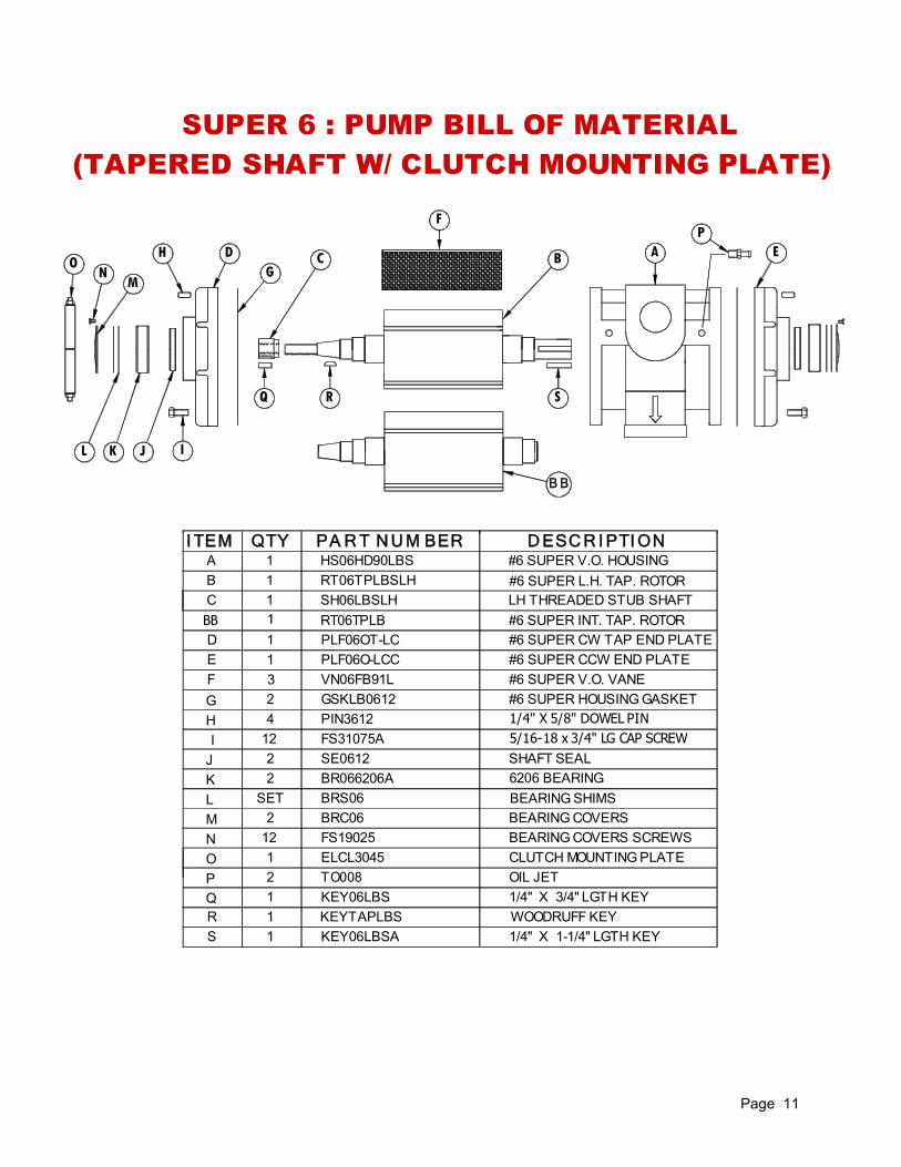
(TAPERED SHAFT W/ CLUTCH MOUNTING PLATE)
SUPER 6 : PUMP BILL OF MATERIAL
Page 9
Page 12
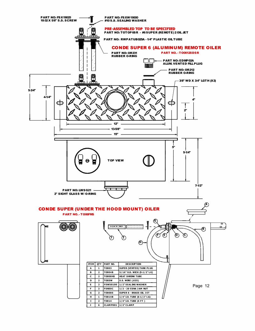
13-5/8"
12"
4-1/4"
5-3/4"
2"
4"
3/8" WD X 3/4" LGTH (X2)
PART NO: EDMP02A
ALUM. VENTED FILL PLUG
RUBBER O-RING
PART NO: OR212
PART NO: FSX19025
10-32 X 5/8" S.S. SCREW
PART NO: FSXW19000
#10 S.S. SEALING WASHER
PART NO: OR231
RUBBER O-RING
PART NO: TOTOP6SR - #6 SUPER (REMOTE) 2 OIL JET
PART NO. - TO0612SDSR
CONDE SUPER 6 (ALUMINUM) REMOTE OILER
PART NO: RWPATUB025A - 1/4" PLASTIC OIL TUBE
CONDE SUPER (UNDER THE HOOD MOUNT) OILER
PART NO. - TO06FMS
15"
5"
5-1/4"
7-1/2"
TOP VIEW
PART NO: LWSG21
2" SIGHT GLASS W/ O-RING
ITEM QTY PART NO. DESCRIPTION
A
B
C
D
E
F
G
H
I
J
A
B
CDEF
G
H
J
1 TO003
TO004B
TO008HS
TOSSW
FSW50100
CLAM P001
S.S. WIRE (.035)
HEAT SHRINK TUBE
SUPER (VENTED) TANK PLUG
5/16" O.D. WICK (9-1/2" LG)
1/2" SEALING WASHER
FSN50C 1/2 - 20 ESNA J AM NUT
TO008S SUPER 6 - BRASS OIL J ET
TO014B 1/4" I.D. TUBE (6-1/2" LG)
TO014 1/4" I.D. TUBE (4 FT )
1/2" CLAM P
2
2
2
2
2
2
2
1
6
H O SE TO PUM P
I
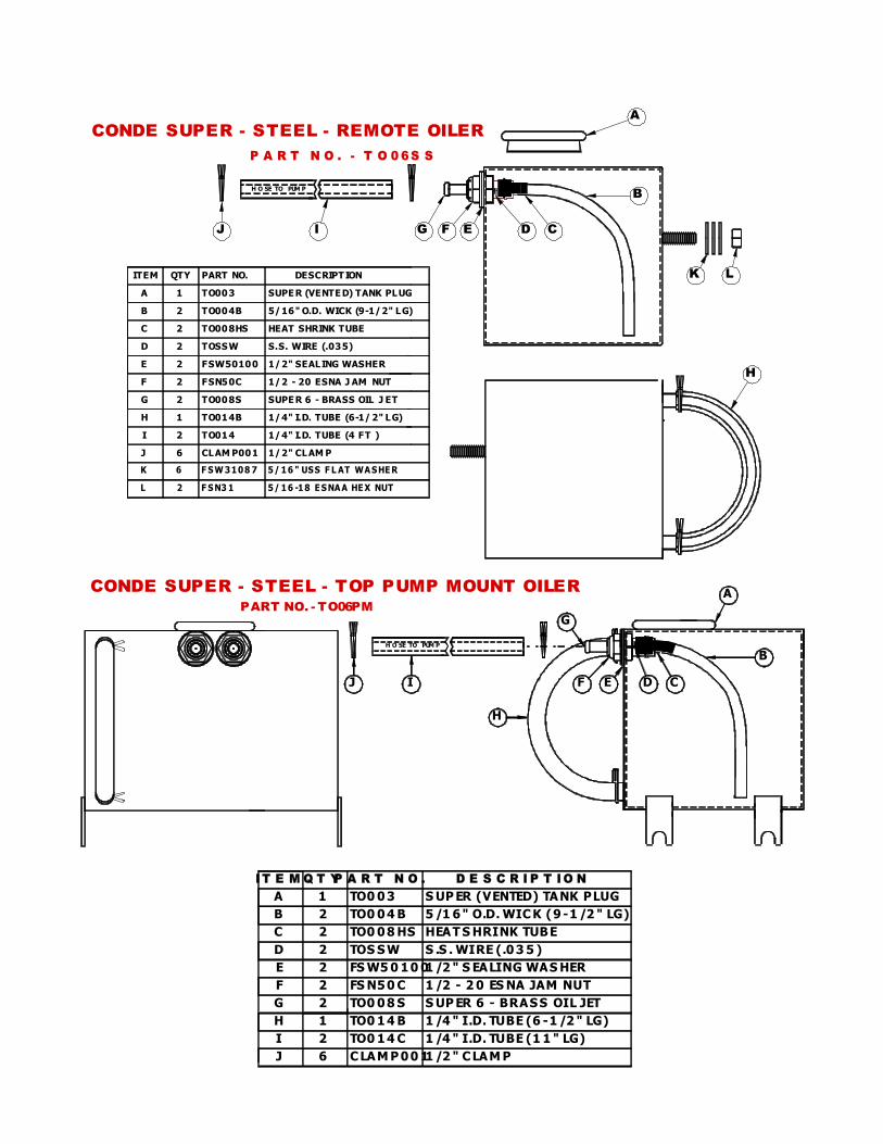
ITEM QTY PART NO. DESCRIPT ION
A
B
C
D
E
F
G
H
I
J
1 TO003
TO004B
TO008HS
TOSSW
FSW50100
CLAM P001
S.S. WIRE (.035)
HEAT SHRINK TUBE
SUPE R (VENTE D) TANK PLUG
5/16" O.D. WICK (9-1/2" LG)
1/2" SEALING WASHER
FSN50C 1/2 - 20 ESNA J AM NUT
TO008S SUPE R 6 - BRASS OIL J ET
TO014B 1/4" I.D. TUBE (6-1/ 2" LG)
TO014 1/4" I.D. TUBE (4 FT )
1/2" CLAM P
2
2
2
2
2
2
2
1
6
A
B
CDEFG
H
J
K L
K
L
6 F SW 3108 7 5/ 16 " USS F L AT WA SHE R
2 F SN3 1 5/ 16 -18 E SNA A HE X NUT
H O SE TO PUM P
I
P A R T N O . - T O 0 6 S S
I T E M Q T YP A R T N O .
A
B
C
D
E
F
G
H
I
J
A
B
CDEF
G
H
IJ
H O SE TO PUM P
1 TO0 0 3
TO0 0 4 B2
2 TO0 0 8 HS
TOS S W2
2 FS W5 0 1 0 0
S UP ER (VENTED) TANK PLUG
5 /1 6 " O.D. WIC K (9 -1 /2 " LG)
HEAT S HRINK TUBE
S .S . WIRE (.0 3 5 )
1 /2 " S EALING WAS HER
2 FS N5 0 C 1 /2 - 2 0 ES NA JAM NUT
TO0 0 8 S2 S UP ER 6 - BRAS S OIL JET
1 TO0 1 4 B 1 /4 " I.D. TUBE (6 -1 /2 " LG)
2 TO0 1 4 C 1 /4 " I.D. TUBE (1 1 " LG)
6 C LAM P 0 0 11 /2 " C LAM P
D E S C R I P T I O N
PART NO. - TO06PM
CONDE SUPER - STEEL - REMOTE OILER
CONDE SUPER - STEEL - TOP PUMP MOUNT OILER
Page 13
SERIAL NUMBER _______________________________ MODEL _______________________________ DATE PURCHASED _______________________________ NOTES: ____________________________________________ ___________________________________________________ ___________________________________________________ ___________________________________________________ ___________________________________________________ ___________________________________________________ ___________________________________________________ ___________________________________________________ ___________________________________________________ ___________________________________________________ ___________________________________________________ ___________________________________________________ ___________________________________________________ ___________________________________________________