Latest Veritas VCS-261 Dumps Question & Answers | Veritas VCS-261

PUMA
Sine Operating Manual
2400-0130C

Sine Operating Manual
ii
Table Of Contents
Chapter 1 - Introduction .................................................................................................. 6
1.1 Introduction ..................................................................................................... 6 1.2 Getting Started................................................................................................. 6 1.3 Software and Manuals ..................................................................................... 6
1.3.1 Software................................................................................................... 6 1.3.2 Manuals ................................................................................................... 6
1.4 Sine Function Features..................................................................................... 7 1.4.1 Safety Features......................................................................................... 9 1.4.2 Options .................................................................................................. 10
1.4.2.1 Security.............................................................................................. 10 1.4.2.2 Automation ........................................................................................ 10
1.4.3 Compatible Equipment........................................................................... 10 1.4.4 Reliability .............................................................................................. 10 1.4.5 User Interface......................................................................................... 10
1.5 Starting The Program..................................................................................... 11 1.5.1 Log In .................................................................................................... 11 1.5.2 Puma Local ............................................................................................ 13 1.5.3 Sine Function Menus ............................................................................. 13 1.5.4 Setting Up Test Parameters .................................................................... 13
1.5.4.1 New Test............................................................................................ 13 1.5.4.2 Existing Test ...................................................................................... 16
1.6 Arranging Screen Components ...................................................................... 16 1.7 Common Areas of Host Dialogs..................................................................... 16
1.7.1 File Selection Box.................................................................................. 16 1.7.1.1 New Selection Command Button........................................................ 17 1.7.1.2 Load File Command Button ............................................................... 17 1.7.1.3 Save As Command Button ................................................................. 17 1.7.1.4 OK Command Button......................................................................... 17 1.7.1.5 Cancel Command Button ................................................................... 17 1.7.1.6 Apply Command Button..................................................................... 17 1.7.1.7 Help Command Button....................................................................... 17
Chapter 2 - Test Concepts and Definitions..................................................................... 18
2.1 Introduction ................................................................................................... 18 2.2 Swept Sine Testing ........................................................................................ 18 2.3 The Sine Control Loop................................................................................... 19
2.3.1 External Load ........................................................................................ 20 2.3.2 A/D Converter(s) ................................................................................... 20 2.3.3 RMS Processing..................................................................................... 21

Sine Operating Manual Table Of Contents Cont'd.
ii
2.3.4 Tracking Filter Processing...................................................................... 22 2.3.5 Control Signal Combination................................................................... 23 2.3.6 Control Spectrum Correction.................................................................. 24 2.3.7 Test Setup Parameters ............................................................................ 24 2.3.8 Sweep Frequency................................................................................... 24 2.3.9 Digital Sine Wave Generation................................................................ 24 2.3.10 D/A Converter ....................................................................................... 25 2.3.11 Attenuation Calculation.......................................................................... 25 2.3.12 Output Attenuation................................................................................. 25 2.3.13 Smoothing Filter .................................................................................... 25
2.4 Channel and Spectrum Definitions................................................................. 26 2.4.1 Reference............................................................................................... 27 2.4.2 Abort ..................................................................................................... 27 2.4.3 Control................................................................................................... 27 2.4.4 Limit...................................................................................................... 28 2.4.5 Error ...................................................................................................... 28 2.4.6 Drive...................................................................................................... 28 2.4.7 Auxiliary................................................................................................ 28 2.4.8 H(f)........................................................................................................ 29
2.5 Reference Spectrum....................................................................................... 29 2.5.1 Reference Segments ............................................................................... 29 2.5.2 Continuity at Segment Boundaries ......................................................... 32
2.6 Safety Features .............................................................................................. 33 2.6.1 Attenuated Output Delay........................................................................ 34 2.6.2 Loop Check Function............................................................................. 34 2.6.3 Control Spectrum Alarm and Abort Limits............................................. 35 2.6.4 Control Signal Loss................................................................................ 36 2.6.5 Operator Abort....................................................................................... 37 2.6.6 Abort Channels ...................................................................................... 37 2.6.7 Limit Channels....................................................................................... 37 2.6.8 Compression .......................................................................................... 37 2.6.9 Alarm and Abort Messages .................................................................... 38 2.6.10 Test Startup Time................................................................................... 38 2.6.11 Test Shutdown Time .............................................................................. 38 2.6.12 Drive Signal Limit ................................................................................. 39 2.6.13 Test Summary List ................................................................................. 39
2.7 Test Scheduling ............................................................................................. 39 2.8 Data Storage and Review............................................................................... 39
2.8.1 Test Setup Parameters ............................................................................ 39 2.8.2 Test Schedule......................................................................................... 40 2.8.3 Spectral Data.......................................................................................... 40 2.8.4 Test Summary........................................................................................ 40

Sine Operating Manual Table Of Contents Cont'd.
iii
Chapter 3 - File Menu ................................................................................................... 41
3.1 Introduction ................................................................................................... 41 3.2 The File Menu ............................................................................................... 41
3.2.1 File Sub-Menus...................................................................................... 41 3.2.1.1 New Menu Option.............................................................................. 41
3.2.1.1.1 Analyzer....................................................................................... 41 3.2.1.1.2 Multi-Ref Modal Acquisition ....................................................... 42 3.2.1.1.3 Waveform Replication.................................................................. 42 3.2.1.1.4 Random........................................................................................ 42 3.2.1.1.5 Sine.............................................................................................. 42 3.2.1.1.6 Sine On Random .......................................................................... 42 3.2.1.1.7 Classical Shock ............................................................................ 43 3.2.1.1.8 Shock Synthesis ........................................................................... 43
3.2.1.2 Open Menu Option............................................................................. 43 3.2.1.3 Close Menu Option ............................................................................ 43 3.2.1.4 SAVE Menu Option............................................................................. 43 3.2.1.5 Save As Menu Option ........................................................................ 43 3.2.1.6 Print Setup ......................................................................................... 43 3.2.1.7 Print ................................................................................................... 43 3.2.1.8 Send................................................................................................... 44 3.2.1.9 Log In ................................................................................................ 44 3.2.1.10 Log Out.......................................................................................... 44 3.2.1.11 System Lock/System Unlock.......................................................... 44 3.2.1.12 Recent File List .............................................................................. 44 3.2.1.13 Exit ................................................................................................ 44
3.2.2 Menus Available During The Test.......................................................... 44 Chapter 4 - Setup Menu................................................................................................. 17
4.1 Introduction ................................................................................................... 17 4.2 Sub-Menus .................................................................................................... 17
4.2.1 Channels ................................................................................................ 17 4.2.1.1 Channel Definition............................................................................... 2
4.2.1.1.1 Column Headings........................................................................... 3 4.2.2 Controls ................................................................................................... 4
4.2.2.1 Test Settings......................................................................................... 5 4.2.3 Profiles .................................................................................................... 9
4.2.3.1 Profile Settings..................................................................................... 9 4.2.4 Schedules............................................................................................... 11
4.2.4.1 Schedule Setup................................................................................... 11 4.2.4.1.1 Sine Schedule Tab........................................................................ 11 4.2.4.1.2 Test Schedule Tab ........................................................................ 12
4.2.5 Limits .................................................................................................... 13 4.2.5.1 Limit Settings..................................................................................... 13

Sine Operating Manual Table Of Contents Cont'd.
iv
4.2.5.1.1 Safety Limits Tab ......................................................................... 13 4.2.5.1.2 Shaker Limits Tab ........................................................................ 14
4.2.6 Search And Dwell .................................................................................. 15 4.2.7 Remote Control Interface ....................................................................... 19 4.2.8 Security.................................................................................................. 19
Chapter 5 - View Menu................................................................................................. 65
5.1 Introduction ................................................................................................... 65 5.2 View Sub-Menus ........................................................................................... 65
5.2.1 Toolbar And Status Bar.......................................................................... 65 5.2.1.1 Toolbar .............................................................................................. 65 5.2.1.2 Status Bar........................................................................................... 65
5.2.2 Test Control ........................................................................................... 68 5.2.2.1 Start ................................................................................................... 68 5.2.2.2 Resume .............................................................................................. 68 5.2.2.3 Pause.................................................................................................. 68 5.2.2.4 Save ................................................................................................... 68 5.2.2.5 Dwell Test.......................................................................................... 69 5.2.2.6 Analysis ............................................................................................. 69 5.2.2.7 Manual............................................................................................... 69 5.2.2.8 Sweep Up........................................................................................... 69 5.2.2.9 Dwell ................................................................................................. 69 5.2.2.10 Sweep Down .................................................................................. 69 5.2.2.11 Sliders ............................................................................................ 69 5.2.2.12 Apply ............................................................................................. 70 5.2.2.13 Abort.............................................................................................. 70
5.2.3 Dwell Status........................................................................................... 70 5.2.4 Test Schedule......................................................................................... 70 5.2.6 Test Control Status................................................................................. 71 5.2.7 Channels Status...................................................................................... 72 5.2.8 Sweep Status.......................................................................................... 72 5.2.9 Message Log Font.................................................................................. 73
Chapter 6 - Test Menu................................................................................................... 74
6.1 Introduction ................................................................................................... 74 6.2 Test Sub-Menus............................................................................................. 75
6.2.1 Abort ..................................................................................................... 75 6.2.2 Start ....................................................................................................... 75 6.2.3 Start Dwell............................................................................................. 76 6.2.4 Start Analysis......................................................................................... 76 6.2.5 Restart ................................................................................................... 76 6.2.6 Pause ..................................................................................................... 77 6.2.7 Manual................................................................................................... 77 6.2.8 Dwell ..................................................................................................... 77 6.2.9 Sweep Up .............................................................................................. 77 6.2.10 Sweep Down.......................................................................................... 77

Sine Operating Manual Table Of Contents Cont'd.
v
6.2.11 Full ........................................................................................................ 78 6.2.12 Half........................................................................................................ 78 6.2.13 Quarter................................................................................................... 78 6.2.14 Drive Update.......................................................................................... 78 6.2.15 Save....................................................................................................... 79 6.2.16 Message Log.......................................................................................... 79
Chapter 7 - Data Menu .................................................................................................. 80 7.1 Introduction ................................................................................................... 80 7.2 Data Sub-Menus ............................................................................................ 80
7.2.1 Display Sine TestData.syn ..................................................................... 80 7.2.2 Choose Report ....................................................................................... 80 7.2.3 File Summary Info ................................................................................. 82
7.2.3.1 Summary Tab..................................................................................... 82 7.2.3.2 StatisticsTab....................................................................................... 82
Chapter 8 - Help Menu.................................................................................................. 83
8.1 Introduction ................................................................................................... 83 8.2 Help Sub-Menus............................................................................................ 83
8.2.1 Help Topics ........................................................................................... 83 8.2.1.1 Contents Tab...................................................................................... 83 8.2.1.2 Index Tab........................................................................................... 84 8.2.1.3 Find Tab............................................................................................. 85
8.2.2 Tutorial .................................................................................................. 86 8.2.3 About PUMA......................................................................................... 86

Sine Operating Manual
2400-0130C
Chapter 1 - Introduction
1.1 Introduction
The Spectral Dynamics Computer Aided Test Suite (CATS) Vibration Control System (Vibration Controller or VCS) program is called PUMA. The current version is 1.5.7 This manual describes Sine Function vibration concepts and the operation of the Sine Function software for the PUMA Use this manual to operate the VCS with the Sine Function closed-loop data generation and signal synthesis program.
This manual is presented in seven chapters relating information about the applicable menus required to set up the operating parameters for the Puma VCS.
1.2 Getting Started
Before beginning, read the PUMA System Description Manual. This will help familiarize the user with the system, and give required information for unpacking, assembly and operation.
1.3 Software and Manuals
Software and manuals (along with vendor manuals, calibration devices and service training) are sold in various combinations. There is also a Receiving Checkout Test issued with the hardware.
1.3.1 Software
The Sine Function closed-loop vibration control program and options are supplied on diskette or CD ROM. This storage medium contains executable code for Sine Function, test parameters, schedule parameters and the micro code for peripheral devices.
1.3.2 Manuals
The PUMA VCS is supplied with a set of two system manuals and an application manual.
• PUMA System Description Part Number 2400-0100
• PUMA Diagnostic Manual Part Number 2400-0103
Other manuals may be included as purchase options.

Sine Operating Manual Introduction
Chapter 1 2400-0130C
1.4 Sine Function Features
The PUMA VCS and the Sine Function program provide digital real-time closed loop shaker control for production testing, design qualification and reliability testing applications. The system allows the definition, simulation, and closed loop control of a Sine Function vibration excitation shaker system. The technical specifications of the Sine Function software are listed in Table 1-1.
Table 1-1. Sine Function Technical Specifications
Control Methods
Control Loop True analog-quality sine sweep with a double precision integrated phase
algorithm for low distortion
Control Performance
Dynamic Range Greater than 80dB with 0.05 dB level step control over the full range.
Output Signal Analog-quality digital sine generation, using a double precision integrated phase
algorithm for low distortion.
Level Accuracy Control to within ±1dB at a sweep rate of 1 oct/min through a 600 Hz resonance
of a linear system with a Q of 70 with an internal 20% proportional tracking filter
sweep frequency resolution of ±0.5% of the drive frequency.
Loop Time Less than 5 msec for single channel control.
Compression Rate Up to 3,500 dB/sec with unconditionally stable feedback control loop.
Harmonic Distortion <-75 dB at full output
Reference Profile
Definition Up to 500 frequency segments
Segment Types Constant displacement, velocity, acceleration and straight line acceleration (linear
or logarithmic)
Crossover Frequencies Automatically calculated to avoid segment boundary discontinuities
Alarm and Abort Limits Independent positive and negative alarm and abort margins
Sweep Range User-defined sweep range from 1 to 5,000 Hz; and 0.01 to 10,000 Hz
(Premier Optional)
Sweep Resolution User-defined resolution of 450 to 800 points per sweep; 450 to 2,400 points per
sweep (Premier) optional
Spectrum Dynamic Limits Acceleration range, maximum or minimum acceleration, maximum velocity and
maximum displacement
Limit Profiles (Optional)
Definition Up to 500 frequency segments
Segment Types Constant displacement, velocity, acceleration and straight line acceleration (linear
or logarithmic)
Crossover Frequencies Automatically calculated to avoid segment boundary discontinuities
Number Up to the number of active channels minus one (Premier)
Sine Operating Manual Introduction
Chapter 1 2400-0130C
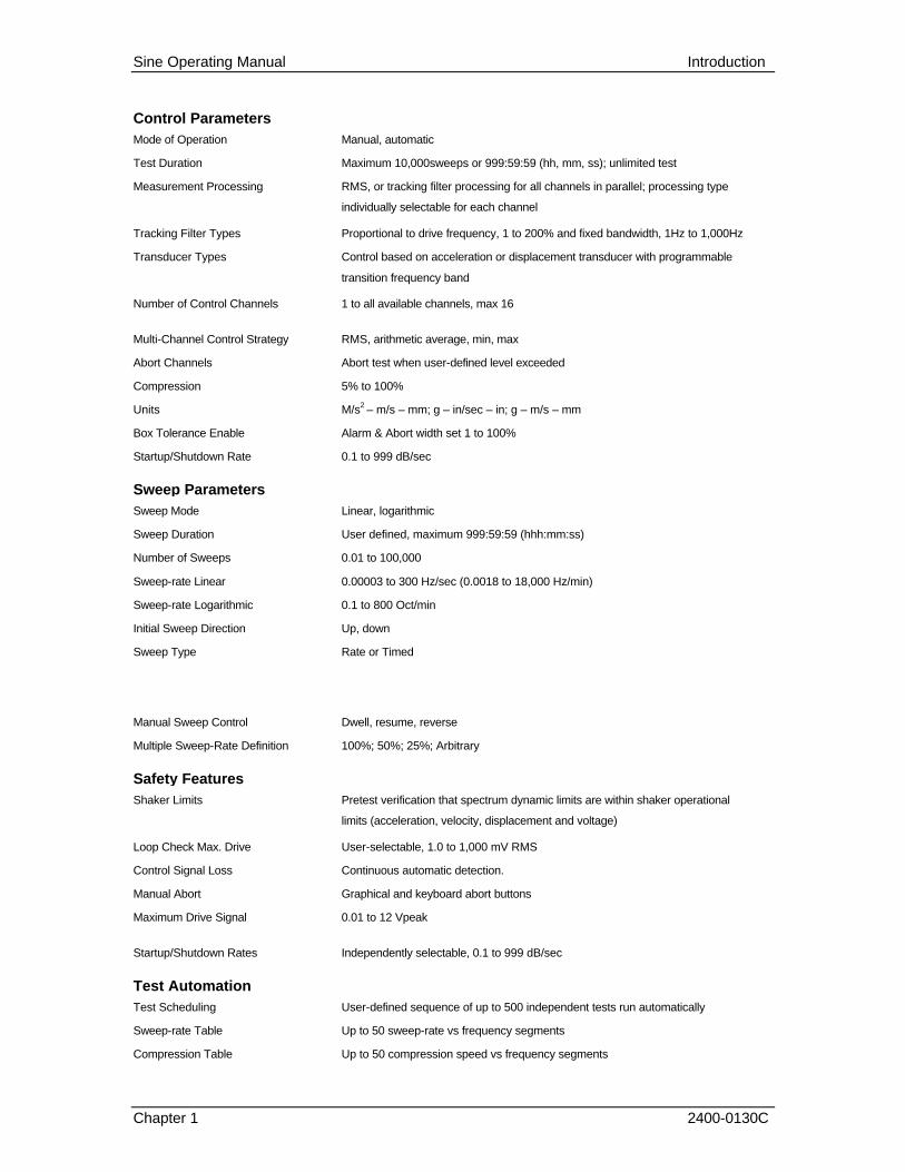
Control Parameters
Mode of Operation Manual, automatic
Test Duration Maximum 10,000sweeps or 999:59:59 (hh, mm, ss); unlimited test
Measurement Processing RMS, or tracking filter processing for all channels in parallel; processing type
individually selectable for each channel
Tracking Filter Types Proportional to drive frequency, 1 to 200% and fixed bandwidth, 1Hz to 1,000Hz
Transducer Types Control based on acceleration or displacement transducer with programmable
transition frequency band
Number of Control Channels 1 to all available channels, max 16
Multi-Channel Control Strategy RMS, arithmetic average, min, max
Abort Channels Abort test when user-defined level exceeded
Compression 5% to 100%
Units M/s2 – m/s – mm; g – in/sec – in; g – m/s – mm
Box Tolerance Enable Alarm & Abort width set 1 to 100%
Startup/Shutdown Rate 0.1 to 999 dB/sec
Sweep Parameters
Sweep Mode Linear, logarithmic
Sweep Duration User defined, maximum 999:59:59 (hhh:mm:ss)
Number of Sweeps 0.01 to 100,000
Sweep-rate Linear 0.00003 to 300 Hz/sec (0.0018 to 18,000 Hz/min)
Sweep-rate Logarithmic 0.1 to 800 Oct/min
Initial Sweep Direction Up, down
Sweep Type Rate or Timed
Manual Sweep Control Dwell, resume, reverse
Multiple Sweep-Rate Definition 100%; 50%; 25%; Arbitrary
Safety Features
Shaker Limits Pretest verification that spectrum dynamic limits are within shaker operational
limits (acceleration, velocity, displacement and voltage)
Loop Check Max. Drive User-selectable, 1.0 to 1,000 mV RMS
Control Signal Loss Continuous automatic detection.
Manual Abort Graphical and keyboard abort buttons
Maximum Drive Signal 0.01 to 12 Vpeak
Startup/Shutdown Rates Independently selectable, 0.1 to 999 dB/sec
Test Automation
Test Scheduling User-defined sequence of up to 500 independent tests run automatically
Sweep-rate Table Up to 50 sweep-rate vs frequency segments
Compression Table Up to 50 compression speed vs frequency segments

Sine Operating Manual Introduction
Chapter 1 2400-0130C
Schedule Cycles 1 to 99
Channel Setup
Channel Type Control, measure, reference, limit, abort, inactive
Sensitivity 0.001 to 99,999 m/Hg or mV/(m/s2)
Channel Loop Check Enabled, disabled
Channel Label Up to 8 characters for each channel
Transducer Serial Number Up to 10 characters for each channel
On-Line Analysis
Display Functions Control, drive, measurement channel 1 to 16, frequency response function
(magnitude/phase or real/imaginary)
Cursors X and Y value readout, peak search, trace
Scaling of Display Log/linear, auto-scaled/fixed
Real-Time/Stored Data Simultaneous display and overlay of real-time data and any stored data
Resonance Search & Dwell (Optional)
Dwell Modes Fixed frequency, phase tracked
Search Parameters Max no. of resonances, hysteresis, minimum Q value
Resonance Calculation Resonance frequency, Q, phase, level
Dwell Table Parameters Duration, start frequency, dwell frequency, end frequency, dwell phase, alarm
limit, abort limit
Data Storage
Setup Options Every sweep, last sweep, first sweep
Playback Scan through the entire test data file, with adjustable delay and tagging
Documentation
Test Summary Fully documented post-test summary, easily printed or incorporated into any
document using standard word processing software
Run Message Log A text file records all system status messages displayed during test run.
1.4.1 Safety Features
Sine provides the following safety features to protect the operator, the test equipment and the manufacturing operations:
• Shaker Limits
• Password login to prevent unauthorized system operation
• Alarm / Abort messages to indicate abnormal test conditions
• Alarm / Abort tolerance limits set by the operator for each spectral line

Sine Operating Manual Introduction
Chapter 1 2400-0130C
• Total acceleration RMS Alarm / Abort level operator settings for the acceleration spectrum
• User specified active frequency range for Alarm / Abort conditions
• A loop check continuity test automatically precedes each test
• Drive signal clipping to prevent drive level from exceeding a threshold value
• Controlled test startup / shutdown rates
• Aborted testing for any control signal loss or excessive fluctuation
• Manual test abort
• Abort documentation for post-test analysis
1.4.2 Options
The following options may be purchased for use with the system.
1.4.2.1 Security
The Security Option package enables the system administrator to place limits on the system including who has access, what level of access is available to the user and whether or not access is available to people outside the facility.
1.4.2.2 Automation
The Automation Option package includes Remote Control Interface (RCI), Remote Control Panel (RCP), Print Automation, Test Automation, Mission Simulation and True Networking.
1.4.3 Compatible Equipment
The PUMA VCS connects to any commercially available electro-dynamic or electro-hydraulic shaker and amplifier.
1.4.4 Reliability
The PUMA VCS is designed and manufactured with state-of-the-art components and processes that improve the reliability of the system.
1.4.5 User Interface
To control the PUMA VCS, the user manipulates values on a high-resolution color graphics display with a mouse and keyboard. User help information is available for all program functions with a single keystroke or mouse click.

Sine Operating Manual Introduction
Chapter 1 2400-0130C
The color monitor provides real-time displays of:
• Program control menus
• Test definition parameters
• Spectra showing test conditions, with Abort / Alarm information
1.5 Starting The Program The Spectral Dynamics CATS VCS program can be started by either a desktop shortcut icon or through the Start button. The latter path is: <Start>ïPROGRAMSïSPECTRAL
TEST SUITEïPUMA.
1.5.1 Log In
When initiated the {User Log In} Dialog Box (Figure 1-1) appears if the Security option is in place. If there is no Security option the PUMA Program Entry Screen will appear as shown in Figure 1-2. To access the features of the PUMA VCS program the user must have a valid users name and password. See the system administrator for proper users name and password.
Enter a [User Name] and [Password] and click <LOG IN>. The PUMA Program Entry Screen shown in Figure 1-2 will appear. The PUMA Version Splash screen will disappear in several seconds (or can be dismissed by clicking on it) leaving the {New} Dialog Box. Click on SINE, and then click OK. A screen similar to the Spectral Dynamics Viewer (Graph Tool) Default Screen shown in Figure 1-3 appears. What is shown is the last test that was run and is dependent on the parameters previously set with the menu options under Puma Local.
Figure 1-1. User Log In Dialog Box

Sine Operating Manual Introduction
Chapter 1 2400-0130C
Figure 1-2. Puma Program Entry Screen
Figure 1-3. Graph Tool Default Screen

Sine Operating Manual Introduction
Chapter 1 2400-0130C
1.5.2 Puma Local
The Puma Local Window’s Title Bar displays three segments of information. Puma identifies the program that is running. Local indicates the mode that the program is running in and Sine1 (or whatever the default program is) is the name of the test.
In order to initiate any type of test it must be done from the Puma Local Window. To access it, minimize the Graph Tool Screen. Notice that the default is the Analyzer function.
1.5.3 Sine Function Menus
The Puma Local Window’s Sine Function Menu Bar contains six menu selections used by the PUMA Vibration Controller program. They are: FILE, SETUP, VIEW, TEST, DATA, and HELP. Each of these is discussed further within their own chapter.
Using hotkeys can activate many of the menu selections. For instance use <ALT> +<F> to activate the FILE menu. An underlined letter indicates a Hot key.
Select LOG OUT from the FILE menu when the system is unattended, and access to the program is to be restricted. When logged in, the LOG OUT menu item is available (LOG IN is grayed out).
1.5.4 Setting Up Test Parameters
Initiating a test is done by either starting a new one from the very beginning or by running one that has already been set up and saved to a file.
1.5.4.1 New Test
The SETUP Menu information is presented in Chapter 3. The following procedure will enable the user to access the SETUP Menu options.
Procedural Steps
1. On the PUMA Local Screen, click SETUPïCHANNELS or click the <Channel Setup> Button. The Channel Definition Window appears. See Figure 1-4.
Figure 1-4. Channel Definition Window
Sine Operating Manual Introduction
Chapter 1 2400-0130C
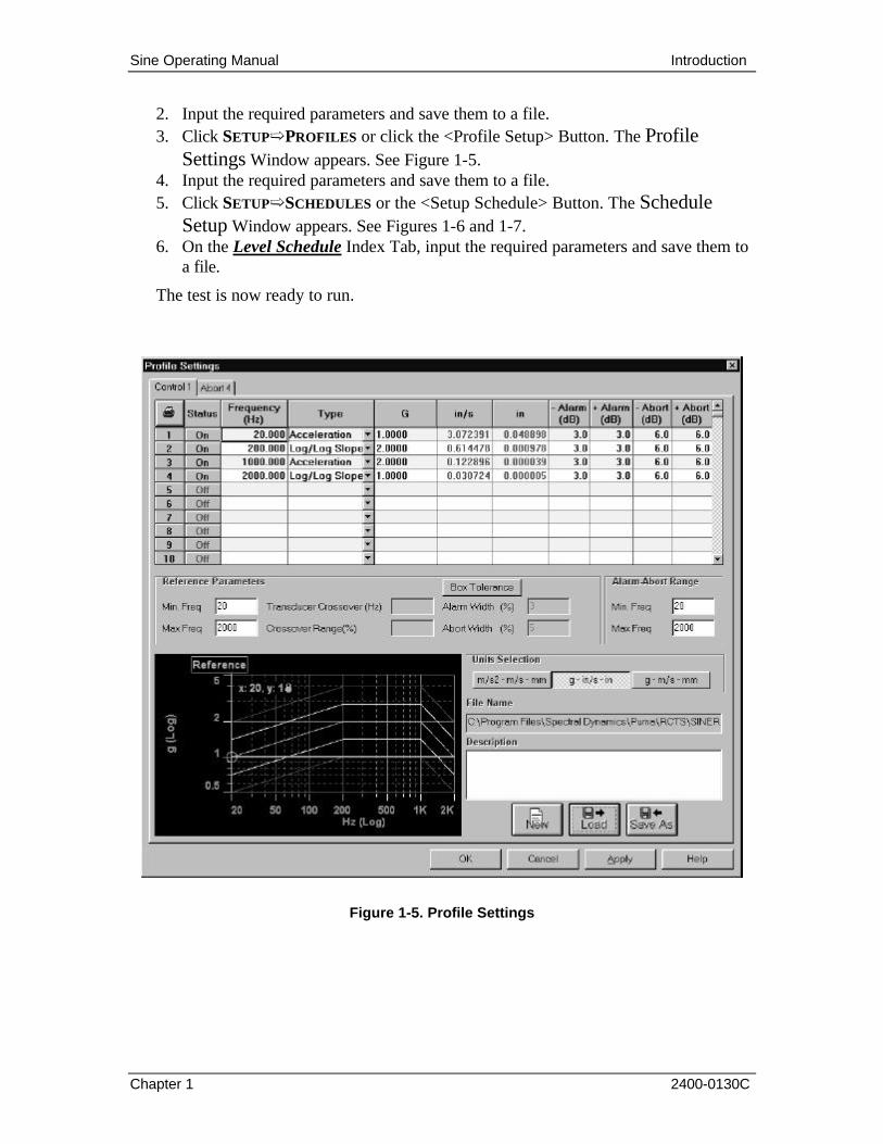
2. Input the required parameters and save them to a file. 3. Click SETUPïPROFILES or click the <Profile Setup> Button. The Profile
Settings Window appears. See Figure 1-5. 4. Input the required parameters and save them to a file. 5. Click SETUPïSCHEDULES or the <Setup Schedule> Button. The Schedule
Setup Window appears. See Figures 1-6 and 1-7. 6. On the Level Schedule Index Tab, input the required parameters and save them to
a file.
The test is now ready to run.
Figure 1-5. Profile Settings

Sine Operating Manual Introduction
Chapter 1 2400-0130C
Figure 1-6. Sine Schedule Tab of the Schedule Setup Window
Figure 1-7. Test Schedule Tab of the Schedule Setup Window

Sine Operating Manual Introduction
Chapter 1 2400-0130C
1.5.4.2 Existing Test
Procedural Steps
1. On the PUMA Local Screen, click FILEïNEW. The {New} Dialog Box appears. See Figure 1-7.
2. Click SINEï<OK>.Click FILEïOPEN.
3. Select appropriate drive and file
4. Click <Open> on the standard Windows File {Open} Dialog Box.
The test is ready to run.
Figure 1-8. NEW Dialog Box
1.6 Arranging Screen Components
During the test the screen can become cluttered and difficult to manage. Some components can be minimized; some have to be sized while others can only be open or closed.
The Graph Tool Window and its components can be minimized while the test is running. The Puma Local Window components can be minimized, closed or hidden, but the window itself cannot be minimized during a test. Instead, it can be sized to help with the presentation and to keep it from interfering with the procedure. With all the components minimized the PUMA Local Window would appear as shown in Figure 1-9. Between or before tests begin the PUMA Local Window can be minimized like any other.
Figure 1-9. PUMA Local Window With Everything Minimized
1.7 Common Areas of Host Dialogs
The layout of screens, windows and dialog boxes sometimes differs from one menu option to another. Even though the command buttons may be in a different position, they will work the same from one menu option or function to another.
1.7.1 File Selection Box
Throughout PUMA there is a need to save the parameters of tests, load those same parameters for another test or just start on something brand new. The File Selection Box (FSB) is shown in the lower left hand corner of Figures 1-4 and 1-6 and the lower right hand corner of Figure 1-5. It is a common Windows tool and is used throughout the PUMA platform though sometimes the format is somewhat different. The components of

Sine Operating Manual Introduction
Chapter 1 2400-0130C
the FSB are outlined below for the primary setup areas of Channel Definition, Profile Settings and Schedule Setup.
1.7.1.1 New Selection Command Button
• Channel Definition The path / name of the currently open file is deleted from the File Name text box. It does not delete the numbers from any of the columns. It is not active during a test.
• Profile Settings Clears all columns of data. It is not active during a test.
• Schedule Setup Clears all columns of data. The path / name of the currently open file is deleted from the File Name text box. It is not active during a test.
1.7.1.2 Load File Command Button
This button reacts the same way in all three parameter input areas. The {Open} Dialog Box is displayed for the user to choose a file to be loaded. All three areas are active during a test.
1.7.1.3 Save As Command Button
This button also reacts the same way in all three parameter input areas. The {Save As} Dialog Box is displayed for the user to save a file. All three areas are not active during a test.
1.7.1.4 OK Command Button
This button accepts any changes made, applies them and closes the open dialog box.
1.7.1.5 Cancel Command Button
This button closes the open dialog box without applying any changes that may have been made.
1.7.1.6 Apply Command Button
This button applies any changes that have been made and keeps the dialog box open.
1.7.1.7 Help Command Button
This button launches the on-line help. If a dialog box is open it must first be closed to launch the help menus.

Sine Operating Manual
2400-0130C
Chapter 2 - Test Concepts and Definitions
2.1 Introduction
This section discusses closed loop swept sine vibration testing, and introduces the terminology used to describe the swept sine control capabilities provided in the Sine program.
The Sine program for the VCS provides a digital, closed-loop, multi-channel control capability for performing a variety of swept sine vibration tests. The program generates a sinusoidal digital signal of changing frequency that is converted to an analog signal. This signal is passed through a digital attenuator and sent to the drive amplifier of an external load (shaker and device under test). The system then accepts analog response signals from the external load accelerometer amplifiers, digitizes these analog signals, and converts them to a single acceleration level that characterizes the behavior of the external load at the current drive signal frequency. The drive signal frequency and amplitude are continuously controlled so that the response signals produce acceleration levels that match the reference spectrum you specify.
The reference spectrum and associated parameters describe how the frequency and amplitude of the drive signal vary with time. Frequency control is specified by the start and end frequencies for the drive signal, how the frequency sweeps between these limits, and how many times the drive spectrum sweeps between the limiting frequencies. Amplitude control is specified by the shape of the reference spectrum, which indicates desired amplitude versus frequency relationship.
2.2 Swept Sine Testing
During manufacturing, shipment, and use, all products encounter stress. Swept sine tests are performed on both prototype and production line products to ensure that the product will survive actual production, shipping, and in-use conditions.
Product vibration testing is conducted by subjecting the product to a stress - mechanical vibration. This mechanical vibration can identify design weakness, and allow early correction of design problems.
Sine vibration environments contain only a discrete frequency for a sine wave that changes frequency over time. A sine vibration environment is used to locate resonance or bending modes in test articles.The Vibration Controller can generate a wide range of sine vibration environments to satisfy any commercial, industrial, or military test requirements. These tests subject the

Sine Operating Manual Test Concepts & Definitions
Chapter 2 2400-0130C
test unit to single-frequency excitation over a specified frequency range (swept sine) or at a fixed frequency if the sweep is halted (non sweeping sine). The test setup parameters are used to define a Sine test. These parameters include the frequency range to be covered by the sweeping sine wave, the sweep rate, the total test time in terms of absolute time or the number of sweeps, and a reference spectrum that specifies the desired amplitude versus frequency relationship over the sweep range. During a test, you can halt the sweep (so that the test unit is excited at a constant frequency), resume the sweep in the same direction or in the reverse direction, and vary the sweep rate.
Real-world vibration environments typically exhibit multiple frequencies or frequencies covering an entire range. Nevertheless, single-frequency sine testing provides a means of:
• Investigating the dynamic properties of a unit • Studying the effects of the excitation frequencies on the unit's performance
characteristics • Determining the resonant or critical frequencies where the unit's performance is
degraded or damage occurs Using these sine test capabilities, you can conduct a modal survey of the resonance's of the unit.
2.3 The Sine Control Loop
Figure 2-1 identifies the major processes that take place in the Sine control loop.
Excitation Signal Response Signal(s)
Vibration Control System
External Load
A/D Converter
Control Amplitude Calculation
Control Signal
Combination
Test Setup
Parameters
Amplitude Correction
Sweep Frequency Calculation
Digital Sine Wave Generation
D/A Converter
Output Attenuation
Figure 2-1. Overview of Sine Control Loop

Sine Operating Manual Test Concepts & Definitions
Chapter 2 2400-0130C
The Sine Control Loop consists of the Vibration Controller and an external load. The external load consists of: the shaker, power amplifier, fixture, unit being tested, accelerometer(s), and the charge amplifier(s) that produce the vibration response signal(s). The VCS initiates and terminates the test, generates the excitation signal, and monitors all test operations.
The Sine test to be performed is completely defined by the test setup parameters you enter before running the test. The setup parameters include the sweep limits, the sweep rate, and the reference spectrum. The reference spectrum establishes a frequency versus amplitude relationship for the test. For each frequency in the test range, the reference spectrum specifies the amplitude of the sinusoidal vibration for each frequency in the test range to which the unit will be subjected.
Each response signal from the external load is converted from analog to digital form by an A/D converter. An amplitude value is calculated from the digitized data received on the input channels. The amplitude values from the individual channels are then combined to form a single value that represents the composite vibration amplitude of the unit being tested.
The Sine program now computes the current excitation frequency (based on the minimum and maximum test frequencies, the frequency of the last loop, the current time, and the sweep rate). The computed frequency value is used in two ways. First, a digital sine wave with the computed frequency is generated and is converted from digital to analog form. Second, the user selected vibration amplitude at the current frequency is computed from the reference spectrum and compared with the actual vibration amplitude of the unit under test. Any difference in amplitude between the measured signal and the user-selected reference represents an amplitude error. This error is used to calculate an amplitude correction value. This value is used to change the amplitude of the new analog sine wave. To complete the loop, the corrected sine signal, with updated frequency and amplitude, is then sent from the Vibration Controller to the external load. The loop is repeated for the duration of the sine test, with sweeping frequency and constantly corrected amplitude.
A detailed description follows.
2.3.1 External Load
The external load includes the shaker apparatus and the unit under test. A single output channel from the system carries the drive signal to the shaker power amplifier to excite the load. Up to sixteen accelerometers can be attached to the load. The output signals from the accelerometer amplifiers provide the input signals to the system.
2.3.2 A/D Converter(s)
Each A/D Converter (one per input channel) is continuously sampling the input and supplying the input measurement process with data. You select the input measurement process, RMS or Tracking Filter. The units of the data are volts. You specify certain input channels to be control channels, limit channels, or auxiliary channels. Control channels affect the drive signal amplitude and thus control the external load. Limit channels limit

Sine Operating Manual Test Concepts & Definitions
Chapter 2 2400-0130C
the drive signal amplitude for load safety considerations. Auxiliary channels allow display of additional individual input channels.
Data is sampled simultaneously on each active channel at a constant sampling rate of 51,000 samples per second.
2.3.3 RMS Processing
The data supplied by the A/D converter is squared and sent through a low pass filter by the DFE processor to give a continuous RMS calculation of the input signal amplitude. This continuous RMS calculation will result in an estimate of the input signal amplitude that includes the energy of the fundamental frequency and all associated harmonics up to the maximum test frequency.
Note The DFE operations are completed in parallel for each channel. This technique improves the control loop speed.
The analog input voltage (Vi) for each channel is assumed to be a sine wave with constant amplitude A, at a frequency ωt. The term for the input voltage can be stated as:
sinA tω
The A/D converter supplies the DFE Digital Signal Processor (DSP) with a digital value corresponding to the instantaneous input voltage. The DSP then mathematically process the values as follows:
By squaring the input voltage, we obtain:
2 sinA tω
By using the trigonometric power relationship for 2sin tω , we obtain:
( )2
1 cos22
Atω−
By simplifying terms, we obtain:
2 2
cos22 2
A Atω−
A digital low pass filter is then used to remove the double frequency term, 2
cos2
Atω
leaving a DC value, 2
2
A, which is proportional to the original amplitude A.
To create the RMS value, the square root operation and averaging is completed in the MDSP controller processing.
Sine Operating Manual Test Concepts & Definitions
Chapter 2 2400-0130C
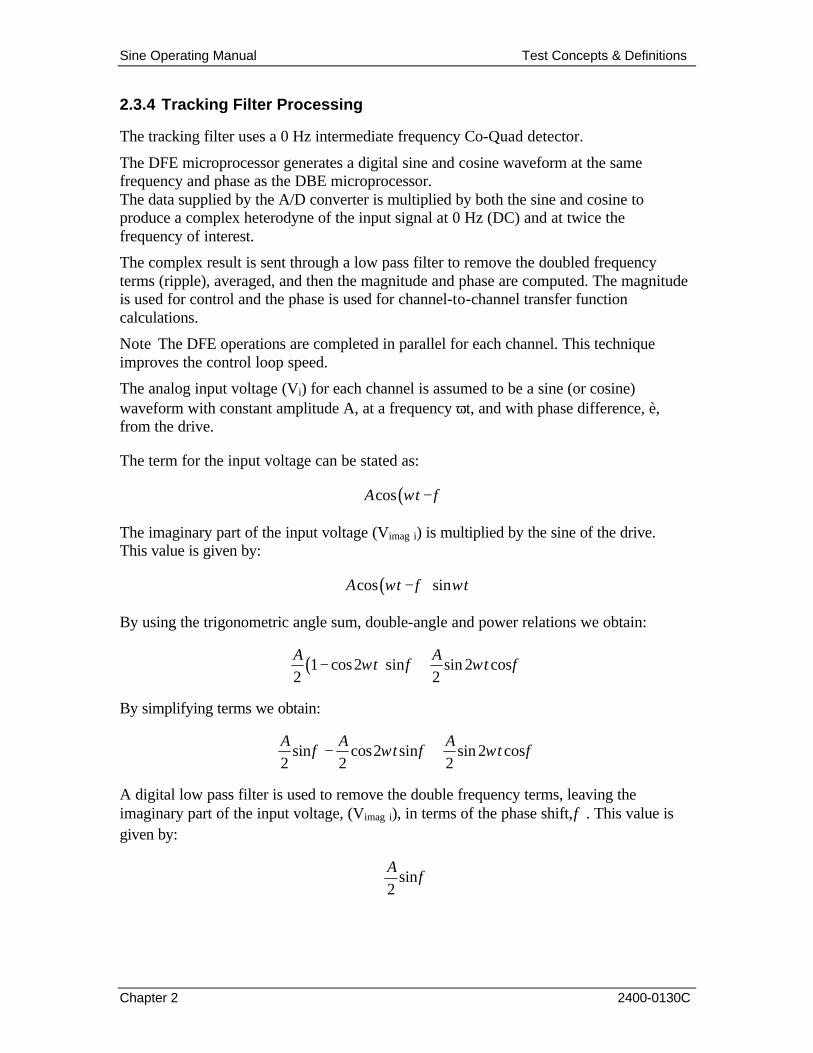
2.3.4 Tracking Filter Processing
The tracking filter uses a 0 Hz intermediate frequency Co-Quad detector.
The DFE microprocessor generates a digital sine and cosine waveform at the same frequency and phase as the DBE microprocessor. The data supplied by the A/D converter is multiplied by both the sine and cosine to produce a complex heterodyne of the input signal at 0 Hz (DC) and at twice the frequency of interest.
The complex result is sent through a low pass filter to remove the doubled frequency terms (ripple), averaged, and then the magnitude and phase are computed. The magnitude is used for control and the phase is used for channel-to-channel transfer function calculations.
Note The DFE operations are completed in parallel for each channel. This technique improves the control loop speed.
The analog input voltage (Vi) for each channel is assumed to be a sine (or cosine) waveform with constant amplitude A, at a frequency ωt, and with phase difference, è, from the drive.
The term for the input voltage can be stated as:
( )cosA tω φ−
The imaginary part of the input voltage (Vimag i) is multiplied by the sine of the drive. This value is given by:
( )cos sinA t tω φ ω−
By using the trigonometric angle sum, double-angle and power relations we obtain:
( )1 cos2 sin sin 2 cos2 2
A At tω φ ω φ− +
By simplifying terms we obtain:
sin cos2 sin sin 2 cos2 2 2
A A At tφ ω φ ω φ− +
A digital low pass filter is used to remove the double frequency terms, leaving the imaginary part of the input voltage, (Vimag i), in terms of the phase shift,φ . This value is given by:
sin2
Aφ

Sine Operating Manual Test Concepts & Definitions
Chapter 2 2400-0130C
The real part of the input voltage (V real i) is multiplied by the cosine of the drive. This value is given by:
( )cos cosA t tω φ ω−
By using the trigonometric angle sum, double-angle and power relations we obtain:
( )1 cos2 cos sin2 sin2 2
A At tω φ ω φ+ +
By simplifying terms we obtain:
cos cos2 cos sin2 sin2 2 2
A A At tφ ω φ ω φ+
A digital low pass filter is used to remove the double frequency terms, leaving the real part of the input voltage, (V real i), in terms of the phase shift,φ . This value is given by:
cos2
Aφ
By combining the real and imaginary parts of the input voltage, the RMS is calculated by:
( ) ( ) ( )2 2* 2reali imagiRMS V V
V = +
By combining the real and imaginary parts of the input voltage, the phase shift is calculated by:
1180tan
2imagi
reali
V
Vφ
π−
=
The term ( )cos tω represents the output signal from the DBE microprocessor. It is also
the imaginary part of the carrier signal used by the DFE microprocessor in the heterodyne process. The presence of the phase term φ in the above equations represents the phase shift in the input signal due to smoothing filters in the DBE, the anti-aliasing filter in the DFE, DBE output signal attenuation dynamics, as well as the dynamics of the device under test. The phase shift due to the DBE and DFE filters are known quantities, which are removed from the phase result above.
2.3.5 Control Signal Combination
Each of the single Mean Square values is then converted to an acceleration level (in g's) using a specified accelerometer sensitivity (in millivolts per g) for that channel.

Sine Operating Manual Test Concepts & Definitions
Chapter 2 2400-0130C
The per channel acceleration levels for each control channel are combined to form a composite control acceleration level A. The following control strategies are selectable for combining the per channel levels:
• The root mean square average:
( )2
1
1 m
ii
A am =
=
∑
• The arithmetic average:
( )2
1
1 m
ii
A am =
=
∑
• The maximum per channel level:
( )maxiA a=
• The minimum per channel level:
( )miniA a=
The composite level is used to update the drive signal amplitude as long as acceleration control is in effect.
2.3.6 Control Spectrum Correction
The composite acceleration level derived from the control signal inputs is compared to the reference level for the current sweep frequency. An error value for this frequency is computed as the ratio of the composite control spectrum level over the reference spectrum level.
2.3.7 Test Setup Parameters
As shown by Figure 3-1, the test setup parameters are used for Control Spectrum comparison and correction before attenuation is calculated.
2.3.8 Sweep Frequency
The program determines the frequency values for the current loop in the frequency sweep by using the sweep start and end frequencies, the sweep rate, and the last frequency output in the previous loop.
2.3.9 Digital Sine Wave Generation
The DBE and DFE microprocessor use a double precision integrated phase sine generation algorithm. This algorithm re-computes the sine phase on a sample-by-sample basis. The result is a smooth sine output signal with an accurate drive frequency sweep rate and low harmonic distortion.

Sine Operating Manual Test Concepts & Definitions
Chapter 2 2400-0130C
2.3.10 D/A Converter The digital drive signal is converted to analog form and has a range of+10 to -10 volts.
2.3.11 Attenuation Calculation The attenuator setting to be applied to the attenuated drive signal is calculated, based on the either the control error or the largest limit channel error. A description of the steps taken to determine the attenuator setting follows.
All input channels designated as control channels are combined using the strategy you define (Avg, Max, or Min). The resulting control signal is compared to the reference amplitude for the current drive frequency, and a control error is calculated.
Each limit channel input signal is compared to its defined limit, which you supply, and an error for each channel is calculated. If any of the limit channel signals exceed their limits, the largest limit channel error is selected as the limit error for the loop.
If there was no limit channel error then the control error is used as the loop error otherwise the limit channel error is used as the loop error.
The loop error is now used for the attenuation calculation. There is one more factor used in the attenuation calculation. That factor is the compression. This quantity varies the speed with which the control loop adapts to changes in response by the external load. It thus allows a direct choice between control speed and control stability of the loop. If a compression of k percent has been specified, then the fraction of the loop error value that is applied to the attenuation calculation is k/lOO.
There are three safety checks made during attenuation calculation. First, if any of the control channel signals do not exceed a threshold defined during loop check, a control signal loss is recognized, and the test is aborted. The only exception to this rule is if the previous control loop attenuation calculation used a limit channel error. In that case, if the input signal of the limit channel in control does not exceed the threshold, a control signal loss is recognized, and the test is aborted. Second, if the input signal of any channel defined as an abort channel exceeds its limit, the test is aborted. Third, if the new attenuation calculation result exceeds a drive limit you define, then the attenuation limit is adjusted to match the drive limit and an alarm is given.
2.3.12 Output Attenuation The DBE microprocessor produces a continuously sweeping sine waveform at a constant full-scale value of ± 10 volts. This signal is kept at the proper level by using the latest calculated attenuation value for the DBE analog attenuator.
2.3.13 Smoothing Filter The shape of the analog drive frame produced by the D/A converter is not smooth but consists of a number of small steps. The smoothing filter operates on the signal to smooth these steps and produce a clean sinusoidal shape. The output of the smoothing filter is the unattenuated drive signal, available at the UNATT connector located at the rear of the system.

Sine Operating Manual Test Concepts & Definitions
Chapter 2 2400-0130C
2.4 Channel and Spectrum Definitions
The various types of channels, signals, spectra, and functions used in the Sine program are identified by an X in Table 2-1 and are defined as follows:
• The term channel is used in regard to the hardware involved with the input or output of data.
• A signal refers to the time-domain data, either analog or digital, that is input or output on a channel.
• A spectrum is a digital, frequency-dependent quantity that is obtained from an input signal or is used to produce an output signal.
• A function is a frequency-dependent quantity that is computed from two or more spectra.
The spectra occurring in the Sine program are produced in real time on a point-by-point basis during a test or analysis run. The reference spectrum is a special case. You define the spectrum as part of the setup operation; it is not derived from real time data.
All data generated by accelerometers attached to the external load and connected to the system's analog-to-digital (A/D) converter constitute the input signals. The A/D channels through which the data enters the system are the input channels. Input signals have units of volts when they enter the system, and are then converted by the program to acceleration levels in units of g's (if appropriate), using accelerometer sensitivities supplied as setup parameters.
Table 2-1. Channels, Signals, Spectra, and Functions

Sine Operating Manual Test Concepts & Definitions
Chapter 2 2400-0130C
2.4.1 Reference
The information for the Reference Spectrum is too large to be described here. It will be described following a description of the other types.
2.4.2 Abort
You specify one or more input channels as abort channels. The input data on these channels are the abort signals.
Abort Channels are relevant only for test runs. You supply a threshold, or abort value (in Volts or g's), as a setup parameter. For each loop, an abort channel error is calculated as the ratio between the abort channel signal and the abort value. If the abort channel signal is above the abort value (the error is greater than 1.0), the test is shutdown. When an abort channel stops a test, a message is printed in the Status Panel Message pane showing the channel, input level, and drive frequency of the event.
The abort channels thus serve to safeguard the test specimen by stopping a test if an excessive response signal level from some point on the unit should occur.
An abort channel can be individually displayed during a test with the display's Auxiliary spectrum selection command.
2.4.3 Control
A separate control amplitude is calculated once each control loop. This calculation is the composite of all input channels specified as a control channel in the active setup parameters. This spectrum is selectable as the "control" spectrum on the spectrum display.
Note (1) Each channel defined as a control channel is also an auxiliary channel.
(2) A separate auxiliary spectrum is calculated from each control channel and may be independently displayed.
The control signals are those input signals you selected to control the external load and therefore affect the drive signal level. You can choose from one to sixteen input signals to be control channels. The A/D channels that carry the selected control signals are designated the control channels. A control channel cannot also be defined as a limit or abort channel.
During each loop, data is received on each control channel, digitized, and the RMS of the data is calculated on a point-by-point basis. The RMS calculation process used is either a Low Pass RMS detector or a Band Pass Tracking Filter, depending on the Measurement process you select. The data is then converted to peak g's (acceleration).
The program computes the composite control amplitude from the acceleration levels of each individual control amplitude. It is this composite amplitude that is compared to the reference amplitude to compute the control error. The composite control spectrum is selectable for display via the Control menu parameter. Individual control channel spectra

Sine Operating Manual Test Concepts & Definitions
Chapter 2 2400-0130C
may be viewed separately by using the display's 'Auxiliary' menu parameter. You can choose any of the following strategies to form the composite amplitude from each individual control amplitude: the minimum acceleration level, the maximum acceleration level, or the arithmetic average of acceleration levels.
2.4.4 Limit
You may specify one or more input channels as limit channels. The input data on these channels are the Limit Response signals. Limit Response channels are relevant only for test runs. You must specify a Limit Profile as a setup parameter. A limit channel error is calculated for each loop as the ratio between the limit channel response and the limit profile.
If the limit channel response is above the limit profile (the error is greater than 1.0), that limit error is used to correct the drive amplitude for the next control loop. If more than one limit channel error signal is greater than 1.0, then the largest limit channel error is selected for correcting the next control loop drive amplitude. When a limit channel takes control of the drive amplitude, a message is printed in the Status Panel Message pane showing the channel, input level, and drive frequency.
The Limit channels are used to safeguard the test specimen by overriding the effect of the control channels if an excessive response signal level from some point on the unit should occur.
2.4.5 Error
The error amplitude computed for each loop of a test is either the control error or the largest limit channel error if a limit channel is in control. The error value is used to update the amplitude of the drive so as to minimize the loop error.
2.4.6 Drive
The drive spectrum is the sine wave data based on the reference spectrum and the error spectrum. The drive signal (or output signal) is the analog sine wave signal produced by the D/A converter and transmitted from the system to the external load during a test. The system output channel over which the drive signal is transmitted is the drive channel.
The sweep and loop control parameters supplied as setup parameters specify the frequency content of the drive signal. The reference spectrum, as modified by the error spectrum, controls the drive signal amplitude. The drive signal excites the device under test in such a fashion that the composite control spectrum matches the reference spectrum.
2.4.7 Auxiliary
You specie one or more input channels as auxiliary channels. The data input on these channels are the auxiliary signals. The series of these acceleration values for each auxiliary channel is the auxiliary spectrum for that channel.

Sine Operating Manual Test Concepts & Definitions
Chapter 2 2400-0130C
If you select the Tracking Filter measurement process in the Control Parameter window, then a phase spectrum for each auxiliary channel will be computed from the input data. The auxiliary channels are used for display purposes.
2.4.8 H(f)
You can specify pairs of input channels in the H(f) Table.
Note When you define channel pairs in the H(f) Table, each of the channel numbers in the channel pair must be defined as a Control or Auxiliary channel in the Channel Table.
The quantities computed by the program depend on the selection made for the Measurement Process setup parameter. If you select RMS, the program computes the transmissibility for each channel pair. The transmissibility is the ratio of channel spectrum magnitudes, and is a non-complex function with magnitude only and no phase; in this case the H(f) phase display is blank.
If you select Tracking Filters as the Measurement Process, the program computes a true H(f) function with magnitude and phase for each channel pair. The Tracking Filter processing is not available for the Analysis function. If you specie channel zero for either channel of a channel pair, the program will compute transmissibility for that channel pair, regardless of the measurement process you select.
2.5 Reference Spectrum
The Reference Spectrum describes the way the amplitude of the sine wave drive signal varies with frequency over the range of the frequency sweep. You can define the reference spectrum through a table in the setup parameters. During a test run, the composite control spectrum value for each loop is compared to the amplitude value of the reference spectrum for the current sweep frequency. The resulting error spectrum value updates the drive signal for the next loop. By this means, the load is controlled to the reference spectrum throughout the test.
2.5.1 Reference Segments
The reference spectrum describes acceleration versus frequency relationship that is the selected excitation for the device under test during a test run of the Sine program. A reference spectrum is established by a number of program parameters that form part of the parameter set entered via the program's setup function. It is defined as a series of up to 100 segments, where a segment of the reference spectrum establishes the acceleration versus frequency relation over a specific portion of the sweep frequency range. Each segment is defined by supplying up to five parameters: type, value, ending frequency, alarm limits, and abort limits. These parameters are described individually in the following paragraphs.

Sine Operating Manual Test Concepts & Definitions
Chapter 2 2400-0130C
Segment Type-
The acceleration versus frequency dependence for a segment may be selected to be any of the following types:
• Constant Displacement
This type specifies a constant peak-to-peak displacement of the test specimen over all frequencies in the segment.
For a constant sinusoidal displacement:
( ) 0sin 2s K ft Sπ= =
the equivalent acceleration is proportional to ft and to the constant displacement, or:
20a Kf S=
If this curve is plotted on a scale of linear acceleration versus linear frequency, it forms a parabola that passes through the origin (since zero displacement at zero frequency yields zero acceleration) and is convex upwards. The curvature of the parabola depends on the constant displacement 0S .
• Constant Velocity
This type specifies a constant zero-to-peak velocity for the test specimen for all frequencies in the segment. For a constant sinusoidal velocity
( ) 0sin 2v K ft Vπ= =
the equivalent acceleration is proportional to f and to the constant velocity, or
0a KfV=
If this relationship is plotted on a scale of linear acceleration versus linear frequency, it forms a straight line that passes through the origin (because zero velocity at zero frequency produces zero acceleration). The slope of the line depends on the constant velocity 0V .
• Constant Acceleration
This type specifies that the test specimen shall be subjected to a constant zero-to-
peak acceleration 0Afor all frequencies in the segment. If this relationship is
plotted on a linear acceleration versus frequency scale, it results in a horizontal
line with height given by the constant acceleration 0A.

Sine Operating Manual Test Concepts & Definitions
Chapter 2 2400-0130C
Straight Line Acceleration Versus Frequency
Specifies that the acceleration value at the end of the previous segment shall be connected by a straight line to the acceleration value for this segment at the end frequency of this segment. Two types are supported: both the acceleration and frequency are linear, or both the acceleration and frequency are logarithmic.
Figure 2-2 shows the acceleration/frequency relationships resulting from each of the segment types on a scale of linear acceleration versus linear frequency, except the straight line acceleration versus frequency, which could also be log acceleration versus log frequency.
Acceleration resulting from constant velocity Vi
Acceleration Resulting from constant displacements
Constant acceleration A
Straight-line acceleration versus frequency (axes can be either linear or logarithmic)
Figure 2-2. Acceleration/Frequency Relationships for Reference Spectrum Segment Types
A
f
A0
A1
A2
A3
A4

Sine Operating Manual Test Concepts & Definitions
Chapter 2 2400-0130C
Segment Value
This quantity gives an amplitude value for the segment. Its interpretation by the program depends on the segment type selected as follows:
• Value = displacement if the segment type is constant displacement.
• Value = velocity, if the segment type is constant velocity.
• Value = acceleration, if the segment type is constant acceleration or straight-line acceleration versus frequency.
Ending Frequency
Specifies the upper frequency limit of the segment. The segment lower frequency limit is fixed either by the start sweep frequency (if this is the first segment of the reference spectrum) or by the upper frequency of the previous segment (if this is the second or a subsequent segment).
An important option is available to you in specifying the upper frequency. That is, if the special value of O (zero) is entered for the frequency, the program computes a crossover frequency that marks the end of this segment and the beginning of the next segment.
Alarm Limits
These limits define a tolerance band in dB above and dB below the reference spectrum level for this segment. If the level of the composite control spectrum exceeds this limit at any frequency in the segment, the program sounds an alarm to alert you of the condition.
Abort Limits
The Abort Limits define a tolerance band in dB above and below the reference spectrum that is wider than and contains the alarm tolerance band. If the level of the composite control spectrum exceeds this outer abort tolerance for 20 successive loops, and if the mode control menu parameter is set to Automatic, the program automatically aborts the test.
2.5.2 Continuity at Segment Boundaries
Each of the segments of a reference spectrum is defined separately. The only inter segment dependence is that a segment's upper frequency becomes the lower frequency for the next segment. The program allows definition of a reference spectrum with discontinuities in the acceleration level from one segment to the next. To control and minimize the occurrence of test abort conditions you should avoid discontinuities; or if they exist, keep the magnitude of the discontinuities small, the abort tolerance bands wide for the segments on each side of a discontinuity, or operate the system in Manual mode (Aborts are disabled).

Sine Operating Manual Test Concepts & Definitions
Chapter 2 2400-0130C
A Box Tolerance feature is also available to make it easier to specify suitable tolerance bands near a discontinuity.
Take care in defining the reference spectrum if you wish to maintain continuity of acceleration levels at the boundaries of adjacent segments. In particular, when specifying segments having constant displacement or constant velocity, it is difficult to determine exactly what the equivalent acceleration level will be at either the lower or upper segment boundary. Use the crossover calculation feature of this program to help you.
2.6 Safety Features
Protection of the external load is of the highest importance. The Sine control program contains a number of safeguards for this purpose; designed to ensure that no abrupt change or out-of-tolerance condition in the drive signal level occurs that might damage the test specimen or actuator equipment. If during a test any of the safety features are executed, the test aborts and shuts down (see Test Shutdown Time in this section). A list of safety features and the frequency with which each feature is monitored is given below in Table 2-2.
Table 2-2. Monitoring Frequency of Safety Features
Sine Operating Manual Test Concepts & Definitions
Chapter 2 2400-0130C
Each feature is designed to protect the external load under a particular set of circumstances. All features except the user abort are automatic and hence do not add to the user workload. Most of the safety features are monitored at least once per control loop; a minimum loop time is thus advantageous not only because it increases control speed but because it also allows more frequent safety checks.
The safety features minimize any possibility of damage to the unit under test. However, you retain final responsibility for proper preparation and maintenance of the external load and signal connections, appropriate use of the safety features and the selection of associated parameters, and careful selection of all maximum signal levels specified for a test.
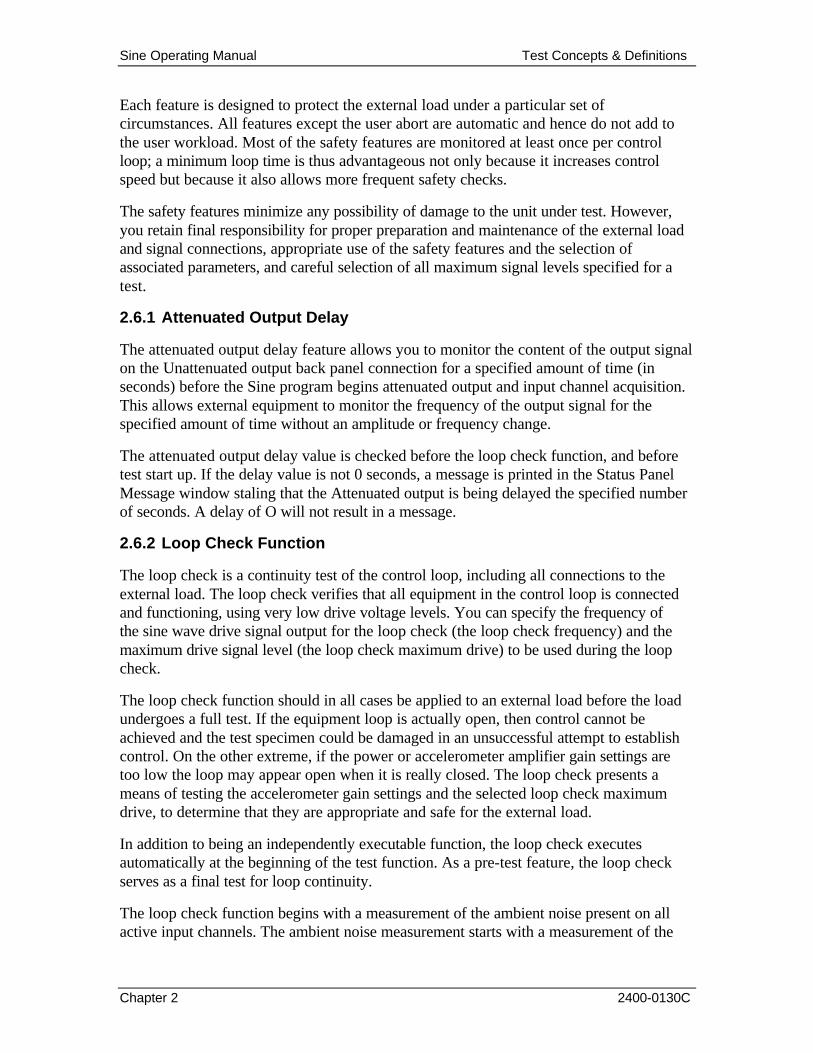
2.6.1 Attenuated Output Delay
The attenuated output delay feature allows you to monitor the content of the output signal on the Unattenuated output back panel connection for a specified amount of time (in seconds) before the Sine program begins attenuated output and input channel acquisition. This allows external equipment to monitor the frequency of the output signal for the specified amount of time without an amplitude or frequency change.
The attenuated output delay value is checked before the loop check function, and before test start up. If the delay value is not 0 seconds, a message is printed in the Status Panel Message window staling that the Attenuated output is being delayed the specified number of seconds. A delay of O will not result in a message.
2.6.2 Loop Check Function
The loop check is a continuity test of the control loop, including all connections to the external load. The loop check verifies that all equipment in the control loop is connected and functioning, using very low drive voltage levels. You can specify the frequency of the sine wave drive signal output for the loop check (the loop check frequency) and the maximum drive signal level (the loop check maximum drive) to be used during the loop check.
The loop check function should in all cases be applied to an external load before the load undergoes a full test. If the equipment loop is actually open, then control cannot be achieved and the test specimen could be damaged in an unsuccessful attempt to establish control. On the other extreme, if the power or accelerometer amplifier gain settings are too low the loop may appear open when it is really closed. The loop check presents a means of testing the accelerometer gain settings and the selected loop check maximum drive, to determine that they are appropriate and safe for the external load.
In addition to being an independently executable function, the loop check executes automatically at the beginning of the test function. As a pre-test feature, the loop check serves as a final test for loop continuity.
The loop check function begins with a measurement of the ambient noise present on all active input channels. The ambient noise measurement starts with a measurement of the

Sine Operating Manual Test Concepts & Definitions
Chapter 2 2400-0130C
DC content. Sine will make internal adjustments to null any ambient DC before making a measurement of the AC ambient noise. The ambient noise RMS measurement presented is over the frequency range 0 to 8kHz.
The loop check outputs a very low level drive signal and gradually increases the signal level to the loop check maximum drive value. The loop check ends successfully when one of three conditions has been met:
1. The input signal is within a specified range of the minimum reference spectrum level.
2. The input signal is 3dB above he ambient noise measurement.
3. The input signal is above 10mV RMS.
The Sine program will check all three conditions each test and select the largest value for each channel. The loop check function will display the message:
Loop Check Completed
in the Status Panel Messages pane when a measured signal reaches, or exceeds, the threshold value for that channel.
The loop check reports an open loop failure condition if the drive signal level reaches the specified loop check maximum drive level and no control signal above the threshold value is detected on one or more of the control channels.
When the program has successfully completed a loop check, the drive signal level gradually decreases to zero.
The system will print the system gain after the Loop Check Completed message. System gain is the ratio of the control signal level to the drive signal level in decibels.
2.6.3 Control Spectrum Alarm and Abort Limits
The Tolerance Bands are the areas both above and below the Reference Spectrum. You choose where the Alarm and Abort bands are active. These bands are displayed during a test and data review.
When the program achieves control of the external load during a test, there is a close match between the amplitudes of the composite control spectrum and the reference spectrum for the current sweep frequency. Conversely, failure to control results in significant discrepancies between the control and reference spectra amplitudes.
Failure to achieve control or loss of control during a test is often due to an equipment malfunction in the external load or to an extreme non-linearity in the structural response of the test unit. Such a condition poses a potential hazard to the external load.
You can specie alarm limits and abort limits for each frequency segment in the reference spectrum, which the program uses to automatically detect amplitude deviations of the

Sine Operating Manual Test Concepts & Definitions
Chapter 2 2400-0130C
control spectrum from the reference spectrum. For each segment you can select a pair of alarm limits in terms of dB above and dB below the reference spectrum level for the segment. Separately and independently, you can specie a pair of abort limits as dB above and below the reference spectrum.
The only restraint placed on the alarm and abort limit values for a frequency segment is expressed by the following relation:
ABORTbelow <ALARMbelow <ref-spectrum <ALARMabove <ABORTabove
The lower and upper alarm limits define an alarm limit tolerance band surrounding the reference spectrum. Similarly, the lower and upper abort limits define an abort limit tolerance band that surrounds both alarm tolerance band and the reference spectrum. You can select the alarm tolerance band for display on the system monitor.
During each loop when the alarm and abort limits are active, the composite control spectrum is compared to the limits. If the amplitude of the composite control signal falls outside the alarm tolerance band, an audible alarm is sounded to alert you. If the control signal is outside the abort tolerance band, the test aborts.
2.6.4 Control Signal Loss
The loss of a signal from any of the control channels during a test can have serious consequences for the test unit. Such a loss means that information required to update the drive spectrum to maintain or achieve control of the external load is missing, and continued output of a drive signal has an unknown effect on the external load. For this reason detection of a control signal loss condition is extremely important, and is reason for immediate shutdown of the test.
The program uses a measurement of the noise level on each control channel, obtained automatically at the start of a test before a drive signal is output. During the test, the program compares the level of each control signal for the current loop to the signal's noise level.
If the signal level is less than or equal to the noise level, control signal loss is assumed and the program aborts the test and initiates shutdown
If you define any input channels as limit channels and a limit channel takes over control of the drive, the control channels will not be checked for control signal loss. Only the limit channel in control of the test is checked for control signal loss. If the signal level of a limit channel in control of a test is less than or equal to the noise level of that channel, control signal loss is assumed and the program aborts the test.
In some situations, you may have a need to modify the way the Safety Parameters detect a Control Signal Loss (CSL).

Sine Operating Manual Test Concepts & Definitions
Chapter 2 2400-0130C
The Sine program provides two methods of modifying the CSL detection.
1. You may use the Safety Parameters Reference CSL Threshold (dB) to define how large a signal is required before the program will recognize a channel loop as closed, and as a consequence, how low a channel signal can drop before a control signal loss is detected.
2. You may use the Safety Parameters CSL Count Threshold: to define how many control loops must detect a control signal loss before the test is shut down.
2.6.5 Operator Abort
The system keyboard has a specially designated ABORT key, and the Control Panel has an ABORT button.
The program continuously monitors the ABORT key and the ABORT button.
When you select ABORT from either the keyboard or the Control panel, the program shuts down immediately. This safeguards the external load if a dangerous or abnormal situation occurs during a test.
2.6.6 Abort Channels
Abort channels allow you to stop a test if the input signal of a channel exceeds a defined limit. You enter a Limit Profile for each defined abort channel. If during any loop of a test run the actual data value received on an abort channel exceeds the profile value, the program aborts the test.
This feature prevents the sine test from over-stressing any points on the external load that are connected to abort channels.
2.6.7 Limit Channels
Limit channels allow you to override the normal update of the drive spectrum amplitude by the composite control spectrum. Enter a Limit Profile for each defined limit channel.
If during any loop of a test run the actual data value received on a limit channel exceeds the profile value, the program performs an amplitude update of the drive signal using limit channel data (see Limit in this section) instead of the error spectrum.
This feature prevents the sine test from over-stressing any of the points on the external load that are connected to limit channels.
2.6.8 Compression
The compression is a measure of how much of the error is corrected on each loop. This allows a user to choose between speed and accuracy. A low compression means that the system takes longer to respond to a change in control signal level, but allows a more gradual, smoother change in the drive signal amplitude.

Sine Operating Manual Test Concepts & Definitions
Chapter 2 2400-0130C
A high compression speed means faster return to the reference spectrum amplitude, but also results in more abrupt changes in the drive amplitude that could cause control instability. The Sine control loop uses the Compression Profile to determine what compression to use during the test sweep. The Sweep/Compression Table is used to define the Compression Profile. You may enter up to 40 segments in each Sweep/Compression Table.
The Compression Profile may be viewed in the Sine Reference Display window. If you need to make adjustments to a selected profile during a test, and save the new profile, the Sine program allows you to override the Compression Profile, then save those changes to a new Sweep/Compression Table.
2.6.9 Alarm and Abort Messages
When parameters are out of assigned limits, the program alerts the user with an audible alarm and prints the alarm condition in the Messages pane. The following conditions will produce alarm or abort messages:
• Loop check function • Control spectrum alarm and abort limits
• Control signal loss • Abort Channels
• Operator abort • Limit channels
• Drive signal limit
2.6.10 Test Startup Time
When a test run begins, the drive signal amplitude increases from 0 volts to the amplitude specified in the reference spectrum for the starting frequency of the run.
You select the rate desired to make this transition in amplitude so as to avoid too rapid a change in the drive signal, based on the nature of the test specimen and the test requirements.
2.6.11 Test Shutdown Time
Test shutdown occurs either normally when a test has completed the specified number of frequency sweeps or as the result of an abort condition, either automatic or operator-initiated.
During test shutdown, the final drive signal continues to be output at the same frequency. The level of the drive signal reduces from its value when shutdown is initiated to a level of O volts.
The test shutdown rate is a selectable test parameter that specifies the rate in dB/sec at which the decrease in signal level to 0 volts takes place. This parameter allows you to make a choice that offers the best protection of the external load.

Sine Operating Manual Test Concepts & Definitions
Chapter 2 2400-0130C
2.6.12 Drive Signal Limit
You can define a test parameter that specifies the maximum drive signal voltage to be output during a test. When this maximum signal is detected, a warning message is presented on the display and the audible tone is sounded to alert you to the high drive signal condition.
2.6.13 Test Summary List
The Data Review function provides summary documentation about the last test function run, and aids in the correct interpretation of any test abort condition that may have occurred.
The information in the Test Summary includes the test ID and test heading of the setup parameters in effect for the run, indicates whether the run completed normally or was aborted, and gives the number of sweeps completed, the run duration and maximum and average amplitude error values.
2.7 Test Scheduling
Sine capabilities include:
• Performing a single test and then initiating another program function,
or
• Automatically performing several tests in a specified sequence, without having to start each individual test in the sequence.
The second kind of operation is called test scheduling.
You prepare for test scheduling by defining the desired sequence of tests, then writing it on disk as a test schedule file.
You may then run the test sequence by choosing test scheduling (and not single-test) operation, selecting the test schedule file and reading the schedule into memory, and executing a test function.
2.8 Data Storage and Review
Several kinds of information used in the Sine program can be stored on and retrieved from disk, using various program functions and menus. Stored information includes test setup parameters, the test schedule, spectra computed during a test, and the test summary listing. In the following, we summarize the storage and retrieval of this information.
2.8.1 Test Setup Parameters
The test setup parameters file is a complete set of the parameters required to define a Sine test for storage and retrieval. You may create and save as many setup files, as you need. Each file defines a single test and is identified by a different user selected Test Name. A test setup file also contains settings for spectrum display parameters.

Sine Operating Manual Test Concepts & Definitions
Chapter 2 2400-0130C
2.8.2 Test Schedule
The test schedule file is a set of Test Names that defines a schedule of tests to be run automatically, and can be stored and retrieved in sequence. You may define as many schedule files, as you need.
2.8.3 Spectral Data
At selected times during a test, you can store on disk, as the spectral data file, the spectra that the Sine program calculates and uses. These spectra represent the test conditions when they were stored.
You may store to the spectral data file during a test, and can display the contents of the file later as an off-line replay of the test.
2.8.4 Test Summary
The test summary contains items of information summarizing the test at the test's end. If a spectrum data file has been created during the test, then the test summary information is automatically stored in that data file.

Sine Operating Manual
2400-0130C
Chapter 3 - File Menu
3.1 Introduction The first of the six menu options in the PUMA Local Sine function of the PUMA Vibration Control System (Vibration Controller) is the FILE Menu option. Refer to the following chapters for other menu options.
3.2 The File Menu When the user selects FILE from the Menu Bar, the menu shown in Figure 3-1 will display. The FILE menu option has 16 sub-menus and a seven-file list contained in a seven-section drop-down menu list. The seven-file list allows rapid access to files that have recently been worked with.
3.2.1 File Sub-Menus
The sub-menus (Figure 3-1) of the File Menu option are outlined below.
3.2.1.1 New Menu Option
When the user selects NEW, the {New} Option List Box will display. See Figure 3-2. It offers the choice of eight test titles that can be initiated (assuming the full complement of tests were purchased). They are:
§ Analyzer § Sine
§ Multi-Ref Modal Acquisition
§ Sine On Random
§ Waveform Replication
§ Classical shock
§ Random § Shock Synthesis
3.2.1.1.1 Analyzer
The Analyzer program provides the ability to analyze various types of signals using a variety of frequency domain measurements. Measurements may be made with flexible triggering, windowing,
sampling and averaging parameters.
Figure 3-1. File Menu

Sine Operating Manual File Menu
Chapter 3 2400-0130C
Figure 3-2. New Option List Box
3.2.1.1.2 Multi-Ref Modal Acquisition
This program allows utilization of multiple references while acquiring modal data.
3.2.1.1.3 Waveform Replication
This program is used to replicate and control an arbitrary waveform.
3.2.1.1.4 Random
The Random Test Suite provides digital real-time closed loop shaker control for production testing, design qualification and reliability testing applications. The system allows the definition, simulation and closed loop control for random vibration excitation of a vibration shaker system.
Random has multiple control frequency ranges with anti-aliasing filters, programmable output processors for time domain randomization, multiple lines of frequency domain resolution and control loop averaging.
3.2.1.1.5 Sine
The Sine test provides a means of applying continuous swept sine vibration excitation over a wide frequency range. A minimum of two input channels simultaneously monitors multiple accelerometers. A digital to analog converter supports drive output rates to 40kHz.
3.2.1.1.6 Sine On Random
This program allows multiple (up to 10) sine tones on a background broadband random profile.

Sine Operating Manual File Menu
Chapter 3 2400-0130C
3.2.1.1.7 Classical Shock
Classical Shock provides a means to apply a pulse of specific magnitude, duration and shape to an object under test. The common pulse types are Half Sine, Sawtooth and Trapezoidal.
3.2.1.1.8 Shock Synthesis
Shock Synthesis provides a means to define a Shock Response Spectrum (SRS) and then synthesize a time domain waveform with a SRS that matches the reference SRS for transfer function equalization. The reference SRS may also be converted to a suitable drive function for SRS amplitude equalization.
Clicking on the NEW menu option and selecting another test while working on a test will initiate the display of a SAVE prompt unless there were no changes made to the test that was downloaded to work on. Please note that there are only four menu options instead of six on the PUMA Local window in the background in figure 3-2. The SETUP and TEST menu options will appear when the new test is launched. Note also that the Analyzer option is the default.
3.2.1.2 Open Menu Option
The OPEN menu option directs the user’s efforts in a different direction. It displays a standard Windows {Open} (file) Dialog Box. The user can navigate to the desired file and open it.
3.2.1.3 Close Menu Option
When CLOSE is clicked a SAVE prompt is displayed if the test that is running has had changes made to it. If no changes were made the currently displayed window will close.
3.2.1.4 SAVE Menu Option
When SAVE is clicked the standard Windows {Save As} Dialog Box appears. It allows the user to save the currently running test to any file folder desired.
3.2.1.5 Save As Menu Option
The SAVE AS menu option also launches the standard Windows {Save As} Dialog Box.
3.2.1.6 Print Setup
PRINT SETUP is a standard Windows command that allows the user to select a printer, the size and source of paper and the orientation of the page. These selections will affect how things are printed when the Print option is used.
3.2.1.7 Print
Click on PRINT to launch the standard Windows {Print} Dialog Box. From here the user may select a printer, what is to be printed and how many copies are required. The option to print to a file is also available.

Sine Operating Manual File Menu
Chapter 3 2400-0130C
3.2.1.8 Send
SEND is a standard Windows command for sending files / tests via e-mail.
3.2.1.9 Log In
The LOG IN option is not available when the user is already using PUMA. It becomes available after logging out.
3.2.1.10 Log Out
The LOG OUT option is only available when the user is logged in to PUMA.
3.2.1.11 System Lock/System Unlock
These two features come with the security options. When SYSTEM LOCK is selected, the system is locked and that option becomes disabled. The SYSTEM UNLOCK option is then enabled. To regain access to the program, the user must select SYSTEM UNLOCK. The {User Log In} dialog box will display and allow the user to login.
3.2.1.12 Recent File List
The recent file list is a standard Windows feature that has been adopted for Puma. It allows the user quick access to the last seven files that have been opened. The path for usage is:
<Start> ï DOCUMENTS ï File Name
3.2.1.13 Exit
EXIT is a standard Windows command. Clicking on this command will cause the current window to close and the application will terminate.
3.2.2 Menus Available During The Test
During the time frame that a test is running there are only four FILE Menu options available for use. They are:
§ PRINT SETUP
§ PRINT § LOG OUT
§ SYSTEM LOCK
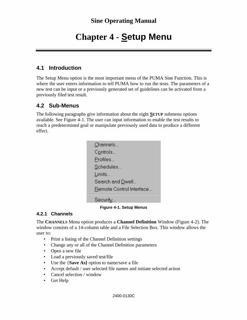
Sine Operating Manual
2400-0130C
Chapter 4 - Setup Menu
4.1 Introduction
The Setup Menu option is the most important menu of the PUMA Sine Function. This is where the user enters information to tell PUMA how to run the tests. The parameters of a new test can be input or a previously generated set of guidelines can be activated from a previously filed test result.
4.2 Sub-Menus The following paragraphs give information about the eight SETUP submenu options available. See Figure 4-1. The user can input information to enable the test results to reach a predetermined goal or manipulate previously used data to produce a different effect.
Figure 4-1. Setup Menus
4.2.1 Channels
The CHANNELS Menu option produces a Channel Definition Window (Figure 4-2). The window consists of a 14-column table and a File Selection Box. This window allows the user to:
• Print a listing of the Channel Definition settings • Change any or all of the Channel Definition parameters • Open a new file • Load a previously saved test/file • Use the {Save As} option to name/save a file • Accept default / user selected file names and initiate selected action • Cancel selection / window • Get Help

Sine Operating Manual Setup Menu
Chapter 4 2400-0130C
The table columns and their functions are discussed in the following paragraphs. The column labels are listed in Table 4-1.
Table 4-1. Channel Definition Window Column Labels
Print Button and Channel Numbers Processing Mode Name Sensitivity mv/g Serial # Weighting (dB) Type ICP Transducer Type Coupling Loop Chk Voltage dB Abort dB Reference
Figure 4-2. Channel Definition Window
4.2.1.1 Channel Definition
Up to four channels can be defined simultaneously.
To set the Channel Definition parameters:
Procedural Steps
5. Access the Channel Definition Window in accordance with the procedure in paragraph 1.5.
6. Load file or set parameters as required. 7. Save to keep changes (choose {Save As} if information is to be saved
independently from the loaded file).
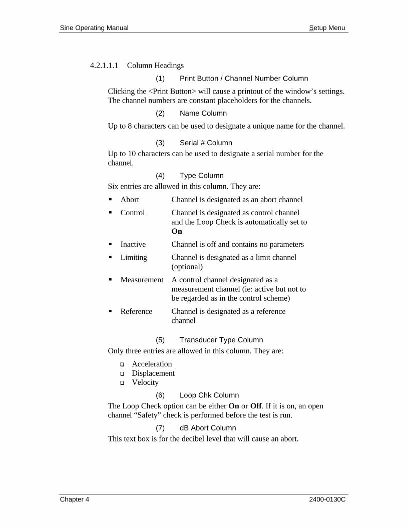
Sine Operating Manual Setup Menu
Chapter 4 2400-0130C
4.2.1.1.1 Column Headings
(1) Print Button / Channel Number Column
Clicking the <Print Button> will cause a printout of the window’s settings. The channel numbers are constant placeholders for the channels.
(2) Name Column
Up to 8 characters can be used to designate a unique name for the channel.
(3) Serial # Column
Up to 10 characters can be used to designate a serial number for the channel.
(4) Type Column
Six entries are allowed in this column. They are:
§ Abort Channel is designated as an abort channel
§ Control Channel is designated as control channel and the Loop Check is automatically set to On
§ Inactive Channel is off and contains no parameters
§ Limiting Channel is designated as a limit channel (optional)
§ Measurement A control channel designated as a measurement channel (ie: active but not to be regarded as in the control scheme)
§ Reference Channel is designated as a reference channel
(5) Transducer Type Column
Only three entries are allowed in this column. They are:
q Acceleration q Displacement q Velocity
(6) Loop Chk Column
The Loop Check option can be either On or Off. If it is on, an open channel “Safety” check is performed before the test is run.
(7) dB Abort Column
This text box is for the decibel level that will cause an abort.

Sine Operating Manual Setup Menu
Chapter 4 2400-0130C
(8) Processing Mode Column
Only two entries are allowed in this column. They are:
q BB RMS q Fundamental
(9) Sensitivity mv/g Column
The parameter for the ratio obtained by dividing mili-volts by force in g’s. The range is 0.001 to 99,999 mHg or mV/(m/s²)
(10) Weighting (dB) Column
The amount of weighting given to the channel for this test. The allowed range is –20 to 6 dB (-3 dB attenuates the signal on the channel by ½).
(11) ICP Column
The ICP function can either be On or Off. It provides a constant DC current source to power the accelerometers.
(12) Coupling Column
Only three entries are allowed in this column. They are:
q AC– It is used to block the DC component of the signal.
q DC– It is used to pass the DC component of the signal.
q Ground– It grounds the input channel.
(13) Voltage Column
Any value from 0 to 10 may be entered. Zero is the default for Auto.
(14) dB Reference Column
This is the decibel level that this channel will use as a reference. 4.2.2 Controls
The CONTROLS Menu option displays the Test Settings Window. This window has four tabs. They are:
o Sweep Parameters o Control Setup
o Data Storage o Print Automation
At the bottom of each tab are four standard Windows Command Buttons. They are:
• <OK> Command Button This button accepts any changes made, applies them and closes the open dialog box.

Sine Operating Manual Setup Menu
Chapter 4 2400-0130C
• <CANCEL> Command Button
This button closes the open dialog box without applying any changes that may have been made.
• <APPLY> Command Button This button applies any changes that have been made and keeps the dialog box open.
• <HELP> Command Button This button launches the on-line help. If a dialog box is open it must first be closed to launch the help menus.
4.2.2.1 Test Settings
The four Test Settings Window Tabs are described below. See Figures 4-3 & 4-4.
Figure 4-3. Sweep Parameters Tab of Test Settings Window Set for Sweeps

Sine Operating Manual Setup Menu
Chapter 4 2400-0130C
Figure 4-4. Sweep Parameters Tab of Test Settings Window Set for Time
Sweep Parameters
The Sweep Parameters Tab has two group box areas; a list box and a text box. The smaller group box on the left is labeled {Duration} and has a list box and four text boxes. The list box is labeled: [Duration Type]. The text boxes are labeled [Sweeps]; [Test Time (hhh,mmm,sss)]; [Test Start Frequency]; and [Test End Frequency]. Below the {Duration} Group Box area is the [Clear Sweeps] List Box and the [Points per Sweep] Text Box.
On the right hand side of the tab is the {Sweep Parameters} group box area. It consists of four list boxes and five text boxes. The list box options are shown in Table 4-2 and the text box labels are listed in Table 4-3.
Table 4-2. Sweep Parameter List Boxes
Sweep Mode Initial Sweep Direction
Sweep Type Multiple Sweep Rate Definition
Log Up Rate 100 / 50 / 25
Linear Down Timed Arbitrary

Sine Operating Manual Setup Menu
Chapter 4 2400-0130C
Table 4-3. Sweep Parameter Text Boxes
Sweep Time (hhh:mmm:sss)
100% Sweep Rate (Oct/Min)
Sweep Rate 1 (Oct/Min)
Sweep Rate 2 (Oct/Min)
Sweep Rate 3 (Oct/Min)
The user may either define each file through the corresponding file’s dialog box or load the file directly from the {Test Settings} Dialog Box.
Control Setup
The Control Setup Tab (Figure 4-5) has three toggle button boxes. The boxes and their buttons are described below.
• Filter – The filter option allows the user to define how much of the frequency is being used for the test. The button choices are Fixed or Proportional and the text boxes reflect the amount being used.
• Strategy – Allows user to assign the control strategy to be applied to the test. The choices are: Average, Minimum, Maximum or RMS.. Selection of one dictates
how much of the individual control channel level is to be computed and used as the composite control level. Average is the default
• Mode - This box can be set to Manual, Automatic or Auto Only. If auto only is selected the manual mode may not be initiated once the test starts.
+
Figure 4-5. Control Setup Tab of Test Settings Window

Sine Operating Manual Setup Menu
Chapter 4 2400-0130C
Data Storage The Data Storage Tab (Figure 4-6) has one toggle button box, two check boxes and one text box.
Figure 4-6. Data Storage Tab of Test Settings Window
• File Name Toggle Button Box – Defines the way the file name will be generated. The toggle buttons are: Auto Generate, Query and Default.
Auto Generate - Creates a unique file name based on the day, date and time that the
test started.
Query - Prompts user for a file name after starting test.
Default – All test data is saved in a default file. The default file is overwritten each
time the test starts.
• Sweep Save Increment – This shows the number of sweeps that will display prior to the program saving a frame of data.
• Check Boxes Save First Sweep – Saves a frame of data at the tests first sweep.
Save Last Sweep – Saves a frame of data at the tests last sweep.

Sine Operating Manual Setup Menu
Chapter 4 2400-0130C
Print Automation
The Print Automation Tab (Figure 4-7) has two command buttons, a list box, a check box and two radio buttons. This optional feature allows the user to define a series of plots to be automatically generated at the end of each test.
• Command Buttons The command buttons are <ADD> and <REMOVE>.
• Check Box - Enable Printing The check box will enable automatic printing or not.
• Radio Buttons The radio buttons are ALL FRAMES and LAST FRAME.
ALL FRAMES prints each frame of data saved during the test (see Data Storage above).
LAST FRAME prints only the final frame of the test.
Figure 4-7. Print Automation Tab of Test Settings Window
4.2.3 Profiles
The PROFILES Menu Option displays the Profile Settings Window. See Figures 4-8, 4-9 and 4-10. It can have up to three tabs showing. The tabs list the channel numbers and functions of the channels. The tabs can be: Control , Limit and Abort. The Profile Settings Tabs format is outlined below.
4.2.3.1 Profile Settings
Each tab has six sections and is similar to each other. The Control Tab is described below. The top section is comprised of a scroll bar and 11 columns, nine of which can
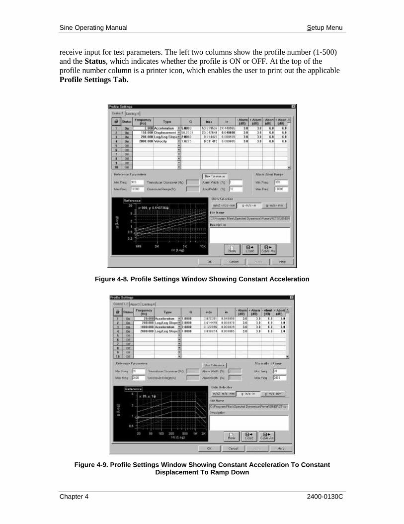
Sine Operating Manual Setup Menu
Chapter 4 2400-0130C
receive input for test parameters. The left two columns show the profile number (1-500) and the Status, which indicates whether the profile is ON or OFF. At the top of the profile number column is a printer icon, which enables the user to print out the applicable Profile Settings Tab.
Figure 4-8. Profile Settings Window Showing Constant Acceleration
Figure 4-9. Profile Settings Window Showing Constant Acceleration To Constant Displacement To Ramp Down

Sine Operating Manual Setup Menu
Chapter 4 2400-0130C
Figure 4-10. Profile Settings Window Showing Constant Acceleration
The middle area is comprised of three sections labeled {Reference Parameters}, {Alarm-Abort Range}. {Units Selection}. The {Reference Parameters} section has three text box pairs and a toggle button labeled <Box Tolerence>. To the right is a two-text box group labeled {Alarm-Abort Range}. They list the minimum and maximum frequency for that range. Below is the {Units Selection} section, which offers a choice of measurement between inches and millimeters. The bottom section has a File Selection Box. Just to the left is a graph window that displays the test profile parameters input by the user.
4.2.4 Schedules
The SCHEDULES Menu Option displays the Schedule Setup Window. It has two tabs labeled Sine Schedule (Figure 4-11) and Test Schedule (Figure 4-12). Both are discussed below.
4.2.4.1 Schedule Setup
Both tabs have four standard Windows command buttons visible at the bottom of the tab(s). They are: <OK>, <CANCEL>, <APPLY> and <HELP>. Please refer to Windows documentation for the use of these buttons.
4.2.4.1.1 Sine Schedule Tab
The Sine Schedule Tab format displays four areas of information. On the upper left side is a tabular display. It consists of two filled columns on the left, three columns of Text Boxes (one of which has pop-up menu buttons), and a scroll bar. The left two columns show the row number (1 to 50) and the Status, which indicates whether the profile is ON or OFF. At the top of the profile number

Sine Operating Manual Setup Menu
Chapter 4 2400-0130C
column is a printer icon, which enables the user to print out the Sine Schedule Tab.
On the upper right side is another tabular display exactly the same with two exceptions. The row number column does not have a printer button and the last column is labeled Compression.
On the bottom left side is a File Selection Box. On the bottom right is a multi-box group. It consists of five text boxes and a check box. The text box labels are:
q Test Start Frequency
q Test Stop Frequency
q Start Up Rate (dB / sec)
q Shut Down Rate (dB / sec)
q Test Level (-dB)
The check box label is: Auto Start Test When Level Reached.
Figure 4-11. Sine Schedule Tab of Schedule Setup Window
4.2.4.1.2 Test Schedule Tab
The Test Schedule Tab is similar to the Sine Schedule Tab. The first two columns and the scroll bar are the same on both tabs. The middle two text box columns labeled Profile and Level Schedule have browser buttons for each profile. Each button activates an {Open} (Files) Dialog Box. The two right hand text box columns are labeled Delay and Cycles. The Delay column shows the amount of time that will elapse between the tests that are scheduled to be run. The Cycles column indicates the number of times the test will cycle before completion. Any data entered on this tab will have to be saved to a file.

Sine Operating Manual Setup Menu
Chapter 4 2400-0130C
Figure 4-12. Test Schedule Tab of Schedule Setup Window
Below the tabular data display is a File Selection Box (FSB) with a <RUN
SCHEDULE> Command Button to the right of it. The FSB is described in chapters 4 and 5. The <RUN SCHEDULE> button will initiate the test(s) that are entered on the Test Schedule Tab.
4.2.5 Limits
The LIMITS Menu Option displays the Limit Settings Window. It has two tabs labeled Safety Limits (Figure 4-13) and Shaker Limits (Figure 4-14). Both are discussed below.
4.2.5.1 Limit Settings
Both tabs of the Limit Settings Window have four standard Windows command buttons visible at the bottom of the tab(s). They are: <OK>, <CANCEL>, <APPLY> and <HELP>. Please refer to Windows documentation for the use of these buttons.
4.2.5.1.1 Safety Limits Tab
The Safety Limits Tab has three group boxes.

Sine Operating Manual Setup Menu
Chapter 4 2400-0130C
Figure 4-13. Safety Limits Tab of Limit Settings Window
Group Boxes - The Group Boxes are labeled {Control Signal Loss}, {Abort Excursions}, and {Loop Check}. The {Control Signal Loss} Group Box has two text boxes labeled: Abort Count and dB Below Min. Reference.
The. {Abort Excursions} text box is labeled Count.
The {Loop Check} Group Box has three text boxes labeled Frequency (Hz), Max Noise (mVRMS) and Max Drive (mVRMS).
4.2.5.1.2 Shaker Limits Tab
The Shaker Limits Tab of the Limit Settings Window has four sets of text boxes, a check box and an FSB. Each text box set has a box for input of either a positive or negative value. The boxes are labeled:
• Acceleration (g) • Displacement (in)
• Velocity (in/sec) • Voltage (V)
The check box is labeled Symetric Limits. If asymmetric limits are desired, deselect the check box to access the lower limit text boxes.

Sine Operating Manual Setup Menu
Chapter 4 2400-0130C
Figure 4-14. Shaker Limits Tab of Limit Settings Window
4.2.6 Search And Dwell
The SEARCH AND DWELL Menu Option displays the Resonance Search and Dwell (RSD) Window. See Figure 4-15. It is comprised of the following elements: Search Parameters Group Box, Profile Information Table, a <Load List> Button, a <Do Search> Button, a List Box, a File Selection Box and two Command Buttons <OK> and <CANCEL>. The first button accepts the changes made and closes the dialog box. The latter button cancels any changes made and closes the dialog box.
The RSD package will automatically identify all of the resonant frequencies by using search criteria (Q value, hysteresis, etc.) and processing the survey sweep. Perform a survey sweep by doing a simple sine sweep across the desired frequency range. Use Bode to identify resonances.

Sine Operating Manual Setup Menu
Chapter 4 2400-0130C
Figure 4-15. Resonance Search and Dwell Window
Hint: If there is a problem dwelling on a resonance, do a fixed dwell on that frequency and see if the phase is stable [H(f) phase plot]. If the frequency is unstable the test structure will have to be modified to provide the system with a stable phase calculation.
Search Parameters Group Box
Text Box Parameters
Max. Resonances 1 – 20 Hysteresis (Points) 2 – 16 Minimum Q Value 0.001 - 999
List Box Parameters
Smoothing Chan Number Off Control Low Med High
Channel Numbers 1 through 16
• Print Button The Print Button will initiate a printout of the Resonance Search and Dwell Window.

Sine Operating Manual Setup Menu
Chapter 4 2400-0130C
• Profile Information Table
The {Profile Information Table} displays 12 columns with 50 rows accessible by a vertical scroll bar. The column labels are:
Profile No. Start Freq Phase
Dwell Status Dwell Freq Level
Units End Freq Alarm Limit dB
Duration Calc Q Abort Limit dB
The Dwell Status and Units columns have drop down lists. The Dwell Status options are: Off; Fixed; Phase or Auto. The Units options are: Time or Cycles.
• Load List Button The <Load List> Button displays an {Open} Dialog Box with a listing of available files/tests to load.
• Do Search Button If a record is selected from the {Open} Dialog Box mentioned above the user is able to initiate a search of that file.
• List Box The LIST BOX shows the Frame ID; Test Time and Level Time.
• File Selection Box Throughout PUMA there is a need to save the parameters of tests, load those same parameters for another test or just start on something brand new. The File Selection Box (FSB) (Figure 4-16) is a common Windows tool and is used throughout the PUMA platform though sometimes the format is somewhat different. (See figures 4-2, 4-8 through 4-12, 4-14 and 4-15.) The File Selection Box consists of various command buttons and two text boxes. The text boxes are File Name and Description. The components of the FSB are outlined below for the primary setup areas of Channel Definition, Profile Settings and Schedule Setup

Sine Operating Manual Setup Menu
Chapter 4 2400-0130C
Figure 4-16. A Typical File Selection Box
New Selection Command Button
• Channel Definition The path / name of the currently open file is deleted from the File Name text box. It does not delete the numbers from any of the columns. It is not active during a test.
• Profile Settings Clears all columns of data. It is not active during a test.
• Schedule Setup Clears all columns of data. The path / name of the currently open file is deleted from the File Name text box. It is not active during a test.
Load File Command Button
This button reacts the same way in all three parameter input areas. The {Open} Dialog Box is displayed for the user to choose a file to be loaded. All three areas are active during a test.
Save As Command Button
This button also reacts the same way in all three parameter input areas. The {Save As} Dialog Box is displayed for the user to save a file. All three areas are not active during a test.
OK Command Button
This button accepts any changes made, applies them and closes the {Open} Dialog Box.
Cancel Command Button
This button closes the {Open} Dialog Box without applying any changes that may have been made.
Apply Command Button
This button applies any changes that have been made and keeps the dialog box open.

Sine Operating Manual Setup Menu
Chapter 4 2400-0130C
Help Command Button
This button launches the on-line help. If a dialog box is open it must first be closed to launch the help menus.
4.2.7 Remote Control Interface
The REMOTE CONTROL INTERFACE Menu Option allows bi-directional communication with other instrumentation. It is explained in a Technical Manual under development.
4.2.8 Security
The SECURITY Menu Option displays the Update Security File Window. See Figure 4-17. This is an option. This window is used to update the security file by either adding or deleting employees names, their privileges or both.
Figure 4-17. Update Security File Window
This window has a list box with access to all employees’ names, a list box with all the current privileges available to each employee, two text boxes dealing with a password and five command buttons. The <OK> and <CANCEL> are standard Windows buttons and are explained in the Windows documentation.
The other three command buttons are <ADD USER>, <DELETE USER> and <UPDATE>. The first two are self-explanatory and the last one acts like a SAVE menu option.

Sine Operating Manual
2400-0130C
Chapter 5 - View Menu
5.1 Introduction The VIEW Menu Option has 13 sub-menus displayed in a four section drop-down menu. The top section lists seven items consisting of a toolbar, a status bar and controls and indicators. The next lower section has four group listings for channels 1 through 16. The last two sections enable the user to select the Sweep Status Box and the Message Log
Font tools. When VIEW is selected from the Menu Bar, the image shown in Figure 5-1 will display. The checkmarks indicate the items that will be seen either in a window or on the desktop during the test.
The number of channels being monitored depends on the package purchased. There can be 4, 10 or 16 channels available. The MESSAGE LOG FONT option displays a standard Windows dialog box that allows editing the font styles. See the Windows documentation for more information about this option.
5.2 View Sub-Menus
Each of the remaining VIEW sub-menu items are described next
5.2.1 Toolbar And Status Bar
When the TOOLBAR and/or STATUS BAR options are selected (Figure 5-1), the Toolbar buttons and Status Bar information will display. See Figure 5-2.
5.2.1.1 Toolbar
The TOOLBAR buttons are shortcuts for various menu items. The first six, and the last three, are standard Windows Toolbar buttons. These are described in the users Windows documentation. Information for the other three buttons, CHANNEL SETUP, PROFILE SETTINGS, and SETUP
SCHEDULE, can be found later in this chapter.
5.2.1.2 Status Bar
The Status bar gives information about various activities currently running on the system. A message displays whenever the cursor touches a shortcut icon with the exception of the PROFILE SETTINGS and Setup Schedule icons. It also has three boxes that act as text boxes to indicate certain functions are available.
Figure 5-1. View Menu

Sine Operating Manual View Menu
Chapter 5 2400-0130C
Figure 5-2. Toolbar, Status Bar and Message Log
5.2.2 Test Control
When TEST CONTROL is selected from the VIEW menu, the Test Control Tool shown in Figure 5-3 will display. The TEST CONTROL Tool, described next, has 12 buttons used to control the test.
5.2.2.1 Start
Click the <Start> button to begin the currently loaded test. After starting the button label changes to read Stop.
5.2.2.2 Resume
Click the <Resume> button to restart the test after a test has been paused.
5.2.2.3 Pause
Click the <Pause> button to pause the currently loaded test.
5.2.2.4 Save
Click the <Save> button to save the current frame of data to a file.

Sine Operating Manual View Menu
Chapter 5 2400-0130C
Figure 5-3. Test Control Tool In Auto Mode
Figure 5-4. Test Control Tool In Manual Mode5.2.2.4 Save

Sine Operating Manual View Menu
Chapter 5 2400-0130C
5.2.2.5 Dwell Test
A Dwell Test can be initiated after the Sine function test is completed by clicking the <Dwell Test> button on the Test Control. The Resonance Search and Dwell Screen appears. See Figure 5-5.
5.2.2.6 Analysis
This button is used to initiate analysis of pre-existing sine data.
5.2.2.7 Manual
Select the <Manual> button to run the test in the manual mode. The TEST CONTROL Tool text boxes will display the numeric values of its slider bar(s).
Note: Manual Mode must be enabled to work any of the following buttons.
Figure 5-5. Resonance Search & Dwell Screen
5.2.2.8 Sweep Up
This button causes the sweep to be up.
5.2.2.9 Dwell
The <Dwell> button causes the sweep to pause.
5.2.2.10 Sweep Down
The <Swp Down> button causes the sweep to be down.
5.2.2.11 Sliders
The sliders are used to adjust the compression or amplitude.

Sine Operating Manual View Menu
Chapter 5 2400-0130C
5.2.2.12 Apply
The <Apply> button causes the changes that were made to be applied to the test.
5.2.2.13 Abort
Select the <Abort> button to abort the currently running test.
5.2.3 Dwell Status
When the DWELL STATUS Menu Option is selected from the VIEW menu, the Resonance Search and Dwell Window shown in Figure 5-5 will display. It is a seven-column table of information relevant to the test being studied. The column labels are:
• Printer Button & File No.
• Units • Duration
• Frequency • Level • Status • Dwell Time
The Units and Status columns have buttons that offer the user choices. At the end of the table is a slider bar that allows access to all 50 files. The <Printer Icon> button allows the user to print the tabular information.
5.2.4 Test Schedule
When TEST SCHEDULE is selected from the VIEW menu, the Test Scheduling window shown in Figure 5-6 will display. This window gives information about the test(s) currently loaded. If the rows are blank, schedule(s) are not loaded in the SETUP Menu portion of the test. To load schedules navigate the path: Setup ï Schedules ñ Schedule Setup Window ññ Test Schedule Tab. Load the schedule(s) and click <RUN SCHEDULE>. The columns may be resized to read the file’s entire path.
Figure 5-6. Test Schedule Menu Option Screen
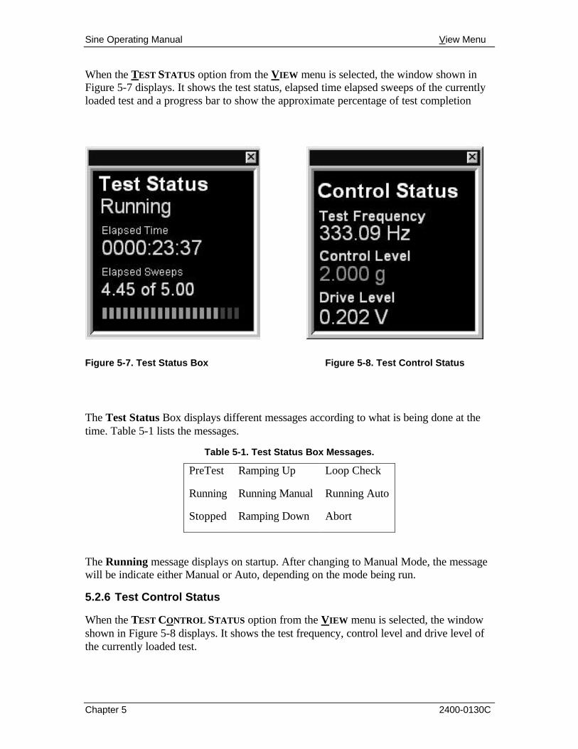
Sine Operating Manual View Menu
Chapter 5 2400-0130C
When the TEST STATUS option from the VIEW menu is selected, the window shown in Figure 5-7 displays. It shows the test status, elapsed time elapsed sweeps of the currently loaded test and a progress bar to show the approximate percentage of test completion
Figure 5-7. Test Status Box
Figure 5-8. Test Control Status
The Test Status Box displays different messages according to what is being done at the time. Table 5-1 lists the messages.
Table 5-1. Test Status Box Messages.
PreTest Ramping Up Loop Check
Running Running Manual Running Auto
Stopped Ramping Down Abort
The Running message displays on startup. After changing to Manual Mode, the message will be indicate either Manual or Auto, depending on the mode being run.
5.2.6 Test Control Status
When the TEST CONTROL STATUS option from the VIEW menu is selected, the window shown in Figure 5-8 displays. It shows the test frequency, control level and drive level of the currently loaded test.

Sine Operating Manual View Menu
Chapter 5 2400-0130C
5.2.7 Channels Status
When Channel Status options (CHANNELS 1
TO 4, CHANNELS 5 TO 8, CHANNELS 9 TO 12, or CHANNELS 13 TO 17) are selected, the activated Channel Status Box is displayed. See Figure 5-9. These give G force information about the channels in four channel increments. The measurement is to the nearest one thousandth.
Figure 5-9. Channel Status Box5.2.8 Sweep Status
The Sweep Status Box is divided into two sections. See Figure 5-10. The upper one has a graphic indicator above the octave per minute rate of the test. The three graphics are:
§ A check mark to indicate the loop check is in progress
§ Arrows pointing up, down, left and right. The arrow up indicates ramping up; if down it indicates ramping down. An arrow pointing to the right indicates the sweep up and when pointing to the left it indicates the sweep down
§ A hand to indicate the test is on hold (dwell / pause)
The lower section of the box has three Sweep Rates Buttons:
q Quarter q Half q Full
These buttons are only available in the Manual mode.
Figure 5-10. Sweep Status Box
+

Sine Operating Manual View Menu
Chapter 5 2400-0130C
5.2.9 Message Log Font
When MESSAGE LOG FONT is selected from the VIEW menu, a standard Windows Font Dialog Box appears. See Figure 5-11. Refer to the Windows documentation for further information. The Message Log is shown in Figure 5-2.
Figure 5-11. Windows Font Dialog Box
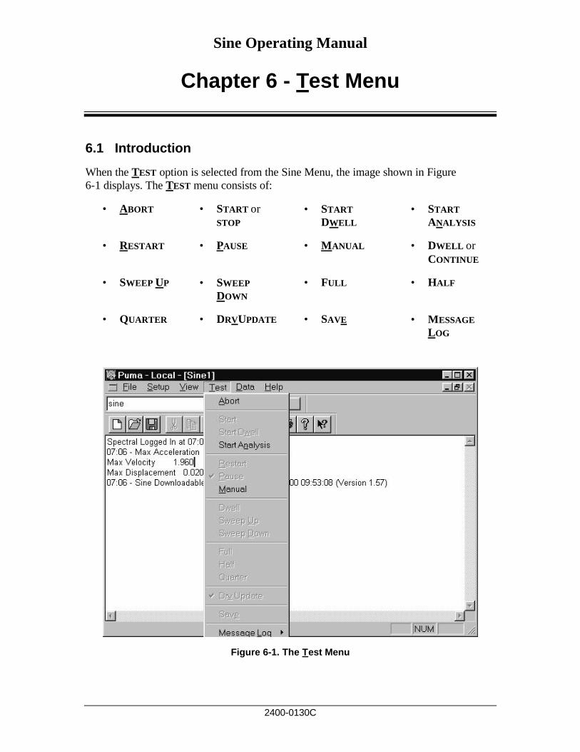
Sine Operating Manual
2400-0130C
Chapter 6 - Test Menu
6.1 Introduction
When the TEST option is selected from the Sine Menu, the image shown in Figure 6-1 displays. The TEST menu consists of:
• ABORT • START or
STOP • START
DWELL • START
ANALYSIS
• RESTART • PAUSE • MANUAL • DWELL or
CONTINUE
• SWEEP UP • SWEEP
DOWN • FULL • HALF
• QUARTER • DRVUPDATE • SAVE • MESSAGE
LOG
Figure 6-1. The Test Menu

Sine Operating Manual Test Menu
Chapter 6 2400-0130C
6.2 Test Sub-Menus
Each of the items on the TEST menu is described in the following paragraphs. Use of these sub-menus allows the user to refrain from having to repeatedly hide or recall the Test Control, which is available in the View Menu Option. The checkmarks indicate that the control is active when available.
6.2.1 Abort
The ABORT menu option allows the user to stop the test immediately in case of a problem. After the problem is corrected the test may be resumed.
6.2.2 Start
The START menu option becomes available to start the test if either of two criteria has been met:
• A previous test file has been loaded
• Test parameters have manually been input for all phases of the test.
After the test has started, the menu options change. Those available are shown in Figure 6-2. The START option changes to read STOP.
Figure 6-2. Test Menu Options During Auto Operation

Sine Operating Manual Test Menu
Chapter 6 2400-0130C
6.2.3 Start Dwell
The START DWELL Menu Option and the <Dwell Test> Button on the Test Control both initiate the dwell test that the parameters were set up for with the SEARCH
& DWELL Menu Option on the SETUP Menu. The dwell test can be stopped with the Test Control <Stop> or <Abort> Buttons and the ABORT or STOP Menu Options.
6.2.4 Start Analysis
After the test is completed the START
ANALYSIS Menu Option becomes available. See Figure 6-3.
6.2.5 Restart
The RESTART menu option allows the user to restart the test from the same point that the test was stopped with a PAUSE or ABORT menu option. The same action can be initiated with the <Resume> Button on the Test Control. When either of these controls is activated, the {Restart Parameters} Dialog Box appears. See Figure 6-4. Input the required parameters and click <OK>.
Figure 6-3. Post Test Menu Option
Figure 6-4. Restart Parameters Dialog Box

Sine Operating Manual Test Menu
Chapter 6 2400-0130C
6.2.6 Pause
The PAUSE menu option stops the test and waits for a command to either continue or stop.
6.2.7 Manual
The MANUAL menu option allows the user to take manual control of the test so that parameters other than the ones originally started with can be used. See Figure 6-5.
6.2.8 Dwell
The DWELL Menu Option allows the user to place a hold on the sweep. See Figure 6-6. After the Dwell is initiated the menu options change again.
6.2.9 Sweep Up
The SWEEP UP menu option allows the user to manually step up the sweep while in the manual mode.
6.2.10 Sweep Down
The SWEEP DOWN menu option allows the user to manually step down the sweep while in the manual mode. See Figure 6-7. Also, compare Figures 6-5 and 6-7.
Figure 6-5. Menu Options in Manual Mode.
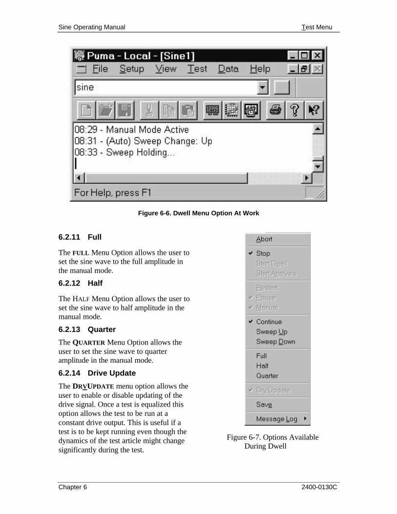
Sine Operating Manual Test Menu
Chapter 6 2400-0130C
Figure 6-6. Dwell Menu Option At Work
6.2.11 Full
The FULL Menu Option allows the user to set the sine wave to the full amplitude in the manual mode.
6.2.12 Half
The HALF Menu Option allows the user to set the sine wave to half amplitude in the manual mode.
6.2.13 Quarter
The QUARTER Menu Option allows the user to set the sine wave to quarter amplitude in the manual mode.
6.2.14 Drive Update
The DRVUPDATE menu option allows the user to enable or disable updating of the drive signal. Once a test is equalized this option allows the test to be run at a constant drive output. This is useful if a test is to be kept running even though the dynamics of the test article might change significantly during the test.
Figure 6-7. Options Available During Dwell

Sine Operating Manual Test Menu
Chapter 6 2400-0130C
6.2.15 Save
The SAVE menu option allows the user to save the test as a file to be used at a later time. This option is only available after new test parameters or a previous test has been loaded. It is also available during the test.
6.2.16 Message Log
The Message Log is the file of information that being generated and is displayed as the test is running. The Message Log submenu has submenus of its own. There is a Pre-Test Dump, a Post Test Dump and a Message Priority selection with three submenus of its own. The submenus are discussed below.
Message Priority
The MESSAGE PRIORITY Menu Option offers the user three levels of Message Priority: High, Medium and All.

Sine Operating Manual
2400-0130C
Chapter 7 - Data Menu
7.1 Introduction
When the user selects the DATA Menu Option the menu shown in Figure 7-1 will display.
Figure 7-1. Data Menu Options
The DATA menu consists of: DISPLAY SINE TESTDATA.SYN, CHOOSE REPORT, FILE SUMMARY INFO, GIM IMPORT/EXPORT, SUMMARY, and CALCULATOR. Each of these menu items is described in the following paragraphs.
7.2 Data Sub-Menus
The three available DATA sub-menus are discussed below.
7.2.1 Display Sine TestData.syn
The DISPLAY SINE TESTDATA.SYN option displays the Test Data Notepad shown in Figure 7-2. After the required parameters are input and the test has been started, the menu option reads: Display (test name). If the parameters have not yet been saved the test name will be a synopsis file (*.syn).
7.2.2 Choose Report
The CHOOSE REPORT option activates an {Open} Dialog Box, which allows the user to search for and select the file that contains the report information required.

Sine Operating Manual Data Menu
Chapter 7 2400-0130C
Figure 7-2. Display Sine TestData.syn Screen
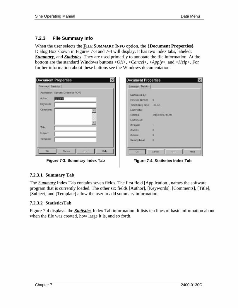
Sine Operating Manual Data Menu
Chapter 7 2400-0130C
7.2.3 File Summary Info
When the user selects the FILE SUMMARY INFO option, the {Document Properties} Dialog Box shown in Figures 7-3 and 7-4 will display. It has two index tabs, labeled: Summary, and Statistics. They are used primarily to annotate the file information. At the bottom are the standard Windows buttons <OK>, <Cancel>, <Apply>, and <Help>. For further information about these buttons see the Windows documentation.
Figure 7-3. Summary Index Tab
Figure 7-4. Statistics Index Tab
7.2.3.1 Summary Tab
The Summary Index Tab contains seven fields. The first field [Application], names the software program that is currently loaded. The other six fields [Author], [Keywords], [Comments], [Title], [Subject] and [Template] allow the user to add summary information.
7.2.3.2 StatisticsTab
Figure 7-4 displays. the Statistics Index Tab information. It lists ten lines of basic information about when the file was created, how large it is, and so forth.

Sine Operating Manual
2400-0130C
Chapter 8 - Help Menu
8.1 Introduction When the user selects the HELP Menu Option from the Sine menu bar, the menu shown in Figure 8-1 will display. This menu consists of HELP TOPICS, TUTORIAL, HINTS, SUPPORT and ABOUT PUMA.
Figure 8-1. The Help Menu
8.2 Help Sub-Menus
The PUMA LOCAL HELP Submenus are explained in the following paragraphs.
8.2.1 Help Topics
The HELP TOPICS option works much the same as its Windows counterpart. The window has three tabs titled Contents, Index and Find. See Figures 8-2, 8-3 and 8-4.
8.2.1.1 Contents Tab
The Contents Tab (Figure 8-2) has a list box with a slider bar and three command buttons below it. The buttons are <DISPLAY>, <PRINT> and <CANCEL>.

Sine Operating Manual
Chapter 8 2400-0130C
Each category of information is preceded by a closed book symbol. Double clicking on the category will open the book and can display two types of sub-category options. One is another closed book indicating further sub-categories. The other option is a page with a question mark on it. Double clicking on this will display the information dealing with the subject.
The Sine category can display three levels of information. When the Contents Tab is closed or cancelled the action resets the window to the default.
Figure 8-2. Help Topics Contents Tab
8.2.1.2 Index Tab
The Index Tab (Figure 8-3) has a text box above the list box. Typing the subject of the search will highlight a category to be opened or display a dialog box prompting a different entry. Below the window are the three command buttons <DISPLAY>, <PRINT> and <CANCEL>. When the Index Tab is closed or cancelled the action resets the window to the default.

Sine Operating Manual
Chapter 8 2400-0130C
8.2.1.3 Find Tab
The Find Tab (Figure 8-4) allows the user to initiate an advanced search for information. Prior to using this option a new list of words / terminology must be generated. Just follow the prompts to build this listing. When the Find Tab is closed or cancelled it is not reset to the default.
Figure 8-3. Help Topics Index Tab
Figure 8-4. Help Topics Find Tab

Sine Operating Manual
Chapter 8 2400-0130C
8.2.2 Tutorial
Some parts of the Tutorial are still being constructed. The Tutorial Screen (Figure 8-5) is divided into two sections, a narrow vertical rectangle on the left and a large
square on the right. The rectangle contains five grayed out graphic buttons. When the cursor arrow is placed on them it changes to a pointing hand and the graphic buttons change color to indicate being active.
The large square contains text messages, two sets of buttons and the link to the Spectral Dynamics Internet Home Page. The top set of three buttons are labeled <Quit>, <Options> and <Begin>. The lower set of six buttons hold the labels that are associated with the particular graphic button in the rectangle. Each time a graphic button is selected the labels on the six buttons change.
Figure 8-5. Help Tutorial Window
8.2.3 About PUMA
The About PUMA Window (Figure 8-6) features a rolling, bouncing cube with pictures of a Puma and the CATS PUMA logo. The right side of the window displays version and build information along with copyright information.
Figure 8-6. The About Puma Screen

Sine Operating Manual
Index
A
A
A/D Converter, i, 20 ABORT, 37 Abort Channels, ii, 8, 27, 37, 38 Abort Limits, ii, 7, 32, 35 ABORT menu, 75, 76 acceleration/frequency relationships, 31 Alarm Limits, 32 Amplitude control, 18 APPLY, i, iv, 17, 5, 18, 70, 82 attenuated output delay, 34 Automation Option, 10 auxiliary channels., 20, 28
B
Box Tolerance, 8, 33
C
CANCEL, i, 17, 5, 18, 19, 82, 83, 85 CATS VCS, 11 channel, 7, 8, 9, 18, 20, 21, 22, 23, 24,
25, 26, 27, 28, 29, 34, 35, 36, 37, 3, 4, 7, 9, 72
Channel Definition, iii, 13, 17, 2, 17, 18 Channel Setup, 9, 13, 65 Channel Status, 72 CHANNELS Menu, 17 Check Box - Enable Printing, 9 Check Boxes, 8 CHOOSE REPORT, 80 CLOSE, iii, 43 Command Buttons, 4, 9, 15 compression, 8, 25, 37, 38, 69 Compression Profile, 38 Constant Acceleration, 30, 10, 11 Constant Displacement, 30, 10
Constant Velocity, 30 control amplitude, 27 control channels, 20, 25, 27, 28, 35, 36 Control Loop, i, 7, 19, 20 Control Methods, 7 Control Parameters, 8 Control Performance, 7 Control Setup, 4, 7 Control Signal Loss, ii, 8, 36, 14 CSL, 36, 37
D
D/A converter, 25, 28 DATA Menu, v, 80 Data Storage, ii, 9, 39, 4, 8, 9 DFE processor, 21 Digital Signal Processor, 21 DISPLAY SINE TESTDATA.SYN option,
80 Do Search Button, 17 Documentation, 9 drive signal, 18, 21, 25, 28, 29, 34, 35,
36, 37, 38, 39 DRVUPDATE menu, 78 DSP, 21 DWELL Menu, 76, 77, 78 DWELL STATUS Menu, 70 Dwell Test, iv, 69, 76
E
Ending Frequency, 32 error amplitude, 28 EXIT, iii, 44
F
FILE menu, 13, 41 File Name Toggle Button Box, 8

Sine Operating Manual Index Cont'd.
B
File Selection Box, i, 16, 17, 11, 12, 13, 15, 17, 18
FILE SUMMARY INFO option, 82 Filter, ii, 25, 7 Frequency control, 18 frequency range, 10, 19, 29, 35, 42, 15 FSB, 16, 13, 14, 17 FULL Menu, 78 function, 9, 13, 16, 22, 26, 29, 34, 35,
38, 39, 41, 43, 4, 69
G
Graph Tool, 11 Group Boxes, 14
H
H(f), ii, 29, 16 HALF Menu, 78 HELP, i, v, 13, 17, 5, 19, 82, 83, 84, 85,
86, 87 hotkeys, 13
L
Limit channels, 20, 28, 37, 38 Limit Profiles, 7 LIMITS Menu, 13 Load File Command Button, i, 17, 18 Load List Button, 17 LOG IN, i, iii, 11, 13, 44 LOG OUT, iii, 13, 44 loop check, 10, 25, 34, 35, 72 Low Pass RMS, 27
M
MANUAL menu, 77 Message Log, iv, v, 9, 65, 68, 73, 74, 79 MESSAGE LOG FONT, iv, 65, 73 MESSAGE PRIORITY Menu, 79 Mode, 8, 2, 4, 6, 7, 69, 71, 77
O
OK, i, 16, 17, 4, 18, 19, 76, 82
On-Line Analysis, 9 OPEN menu, 43
P
PAUSE menu, 77 PRINT, iii, 10, 43, 44, 17, 2, 3, 4, 9, 16,
83, 85 PRINT SETUP, iii, 43, 44 Profile Information Table, 15, 17 Profile Settings, iii, 14, 17, 9, 10, 11, 17,
18, 65 PROFILES Menu, 9 Puma Local Window, 13, 16
Q
QUARTER Menu, 78
R
Radio Buttons, 9 recent file list, 44 Reference Parameters, 11 Reference Profile, 7 reference spectrum, 18, 19, 20, 24, 26,
28, 29, 32, 33, 35, 36, 38 Reference Spectrum, ii, 27, 29, 31, 35 REMOTE CONTROL INTERFACE Menu,
19 Resonance Search & Dwell, 9, 69 RESTART menu, 76 RMS, i, 8, 10, 20, 21, 23, 27, 29, 35, 4, 7 RSD, 15
S
Safety Features, i, ii, 8, 9, 33 SAVE, 43 SAVE AS, 43 Save As Command Button, i, 17, 18 SAVE menu, 19, 79 Schedule Setup, iii, 14, 15, 17, 11, 12,
13, 17, 18, 70 SCHEDULES Menu, 11 SEARCH AND DWELL Menu, 15 SECURITY Menu, 19

Sine Operating Manual Index Cont'd.
C
Security Option, 10 Segment Value, 32 SEND, iii, 44 SETUP Menu, iii, 13, 17, 70, 76 SETUP submenu options, 17 signal, 6, 10, 18, 20, 21, 22, 23, 24, 25,
26, 27, 28, 29, 33, 34, 35, 36, 37, 38, 39, 4, 78
Spectral Dynamics Internet Home Page, 86
Spectral Dynamics Viewer. See Graph Tool
spectrum, 8, 10, 18, 20, 24, 26, 27, 28, 29, 32, 35, 36, 37, 38, 39, 40
Splash screen, 11 START ANALYSIS Menu, 76 START DWELL Menu, 76 START menu, 75 Status bar, 65 STATUS BAR, iv, 65, 68 Strategy, 8, 7 SWEEP DOWN menu, 77 Sweep Parameters, 8, 4, 5, 6 Sweep Save Increment, 8 Sweep Status, iv, 65, 72 SWEEP UP menu, 77 SYSTEM LOCK, iii, 44 SYSTEM UNLOCK, iii, 44
T
Technical Specifications, 7 Channel Setup, 7 Control Methods, 7 Control Parameters, 7
Control Performance, 7 Data Storage, 7 Documentation, 7 On-Line Analysis, 7 Reference Profile, 7 Resonance Search & Dwell, 7 Safety Features, 7 Sweep Parameters, 7 Test Automation, 7
Test Automation, 8, 10 TEST CONTROL, iv, 68, 69, 71, 75, 76 TEST menu, 43, 74, 75 TEST SCHEDULE, ii, iii, iv, 15, 40, 11,
12, 13, 70 test schedule file, 39, 40 test scheduling, 39 test setup parameters, 19, 20, 24, 39 Test shutdown, 38 TEST STATUS, 71 Test Summary, ii, 9, 39, 40 Tolerance Bands, 35 TOOLBAR buttons, 65 Tracking Filter, i, 8, 20, 22, 27, 29 Tutorial Screen, 86
U
UNATT connector. See User Log In, 11, 44
V
VIEW menu, 68, 70, 71, 73 VIEW Menu Option, 65, 75