Pulses To Order - GenRad Experimenter May 1965 · 2012-05-06 · pulses to order programmable...
24
VOLUME 39 NUMBER 5 III Lit; s issue PULSES TO ORDER PROGRAMMABLE SYNTHESIZERS MAY 1965 nOIDS fRA tiLES TRIA n:.c IIi • SA WYEETH SfAIRCASES· STA UL TlPLE PULSES MULTIPLE PULSE RECTANGULAR P'-i LAR PULSES· REe. NOISE· PULSES W ES WITH NOISE COHERENT BURST HERENT BURSTS BINARY WORDS· IS QRDS . BINARY WO TRAPEZOIDS TRA TRIANGLES T A TEETH SAWTn STAIRCASES'STA ",L TlPLE PULSES MULTIPLE puur RECTANGULAR p,", "AR PULSES REe PULn TRA E " RA TRIANGLES , A TEETH SAW ... TAIRtASES STA ""L TIPlE P"" .. SES MYLT l£ PIJL5 RECl ANGULAR .. AR PULSES RfC NO Sf PULS W IET LABS, Inc in the GenRad tradition 534 Main Street, Westbury, NY 11590 www.ietlabs.com TEL: (516) 334-5959 • (800) 899-8438 • FAX: (516) 334-5988
Transcript of Pulses To Order - GenRad Experimenter May 1965 · 2012-05-06 · pulses to order programmable...

VOLUME 39 NUMBER 5
III Lit; s issue PULSES TO ORDER
PROGRAMMABLE SYNTHESIZERS
MAY 1965 nOIDS fRA tiLES TRIA
n:.c IIi • SA WYEETH SfAIRCASES· STA UL TlPLE PULSES MULTIPLE PULSE RECTANGULAR P'-i LAR PULSES· REe. NOISE· PULSES W ES WITH NOISE COHERENT BURST HERENT BURSTS BINARY WORDS· IS QRDS . BINARY WO TRAPEZOIDS TRA TRIANGLES T A TEETH SAWTn STAIRCASES'STA ",L TlPLE PULSES MULTIPLE puur RECTANGULAR p,", "AR PULSES REe -IS~ PULn
TRA E " RA TRIANGLES , A TEETH SAW ... TAIRtASES STA ""L TIPlE P"" .. SES MYLT l£ PIJL5 RECl ANGULAR .. AR PULSES RfC NO Sf PULS W
IET LABS, Inc in the GenRad tradition
534 Main Street, Westbury, NY 11590 www.ietlabs.com
TEL: (516) 334-5959 • (800) 899-8438 • FAX: (516) 334-5988

CONTENTS OF THIS ISSUE
2
Pulses to Order
Flgu,. 1. Modulo. conltruction p .. mi'" choin 0' pluo·lni 10 molt. Iho pull. oon .. olo, ,._
wan' .
P ...
Remote Programming for GR Synthesizers
3
20
1965_GENfIAl 1011010 CO""ANT, WUT COHCO_D, MAn~ U.I .A.
IET LABS, Inc in the GenRad tradition
534 Main Street, Westbury, NY 11590 www.ietlabs.com
TEL: (516) 334-5959 • (800) 899-8438 • FAX: (516) 334-5988

PU LSES TO ORDER The TYI'~; l :m:J-A :\Iodular I'ui tlt'
G.' llI"mtQr if; a pulse kit of almost infinite' pos."ihilitif's. With it onc ( '1111
('(11li;trUf't , to suit hi l; l'['quirC'merlt s Or
his flllLf:Y, II prH('tir'ully infinite Ilumiwr of pu.lS<' !lilupcs :.twJ l'ombi uHtions. As Shl)WIl ill Figun' 1, the gCllerator \'011 -
sist:i or :t !lumber of btlsi{' modulI's nnd It (mnl(' to hold thum. The photogr:tph shows unly Ollt' of :{8,400 f'o mbinatiullR t hu t (:fi ll IX' asse mbled from currently availahle mod l.lea.
Of C.:(l\H1<C, so me :;cicl'tioll must lX' made umolLg l h{'s(' capabilities; the ~ [od\lla r Pulse Generator will no t do ('VC' ry tiling at OIlC('. Su the !It'xt mu tter tl) r'OII~ider is what modlllci; fife ~\'ll il
:lblc. wbat funct ions they I)('rform. and how they ('an be combined for maximum usefulness.
Tht, Typ~; ):m.'J-A ~I odulnr Pulf:!(' ( il' llcralor produces Iiny o r all of the following signals:
• conventional rcdangul:lr puISt,!<
• pu lse bursts • dou blet pulses • pulses with p<,destu\f<
• lUwt'llding I\lld d(':,~'{'ndi]lg stu ir('ll j;('1!\
• triangle!' • trapezoid;.; • 1X'('lIJillr PlllflC:;
• s illglt' pulse:, • binn!')' pultt'rlll! Of words from '1 II)
11'1 bits long IU Hdditioll, it • loeks 011 highN fn'qu t'l lI'ics lip to
ratios (If IlUou t 1.';:1 • ~i('a lcii ill trw' (Iigital fll:,h io tl by
a ny quantity tha t (':111 be fo rlll('d :lfl the prod uet I)f up to 7 Hllm bers Ix'tween'!. a nd I(i
• gctwru.tes time dclays • openlles at puiS(' rcp<'l ition f(('(IUen
l' ies as 101\' as :L'i (' /s aud tip to I .. i .\k/ s internally; dow n to de a nd liP to:2 .\1 (' /5 with t'xtt'rn:ll drivl'
• a 1I0w:.o noi:'lc Ill' lOi lll' wa vc~ lo be nd dt.'tI to pubics
• gives illdl'pcJl{icllL l'OIltrol O\'C'r amplitudes, durations. a nd delays in all ports of complC'x I)ulses
• nmplifics till' pul~s it produ("('s (tip to 400 rnA ill ;)0 ohms )
• gh'cs bot h pOflit ivc a ud negative poJllri ties !;im ulttl lulotl!;].\'
One of the first commerciol pulse generotors wos the Generol Rodio Type 869_A,1 designed ond built originally for defense research praiects in Wortd War It. Square. wove generators, among them the GR Type 769.A, hod been available for some years and were widely used for transient response measure· ments.1 For design and test of pulsed equipment such as radar, television, and pul$e·madulated communication systems, however, test signals of variable dutycycle and fasl rise and fall limes were needed. The Type B69·A fitled the bill in the early days. It was followed by the Type 1391 -A Puhe, Sweep, and TimeDetay Generator and the Type 1217 Unit Pulse Generator, of which the current Type 1217·( is the 10 lest design. The new Type 1395·A Modular Pulse Generator goes several steps further and attows the user to build pubes of practically ony snope thot he wishes.
I H. Ii. S«I" and C. A. Cod1. ··T~. CO ... .,01 Radio P .... C ... .,o ..... " c....o' tad;" h,........." ..... JOft"o,,-f.b,.o,.., 1 '105 · • L t. "'~oi",ba •• " 1'1., ...... , To .. ;"~ ... ith S~"O, . Wo.",," ee-ol ~adio h_i",on",. D", ... ,,-, 19J9,"T,on.i ... , Re· 'p_" 01 Q Bloodeo" S,.t .... " Ibid. "'P'~ 19.1).
3
IET LABS, Inc in the GenRad tradition
534 Main Street, Westbury, NY 11590 www.ietlabs.com
TEL: (516) 334-5959 • (800) 899-8438 • FAX: (516) 334-5988

4
GENERAL RADIO EXPERIMENTER
" ~
1J - 2/1' <1,- .... ~ "' 2/1'
d.- I • .... mOf. Of In •. 1._2 .... mOf. 0. In • • r ", 100 .. .
FII"'. ,. A d •• lan obile' .....
AVAILABLE MODULES
Ao ioitllil complemen t of six modules is offered for tbis instrument.
Type 1395-Pl PRF Unit. A master clock, generating pulses for synchronizing and triggering other plug-ins. It also provides gating and locking fUll ctions and accept.s external dri ve signals, buffering tbem to other modules.
Type 1395-P2 Pulse/Delay Unit. Generates recrongular pulses from 0.1 microsecond to 1.1 seconds, choice of positive or negative polarity or both simulroneously. Geoerates time delays from 0.1 microsecond to 1.1 seconds.
Type 1395-P3 Pulse Shapero Gives independent control over the rise lind fall times of leading and trailing edges of pulses. Rise Ilnd fall times call be varied from 0.1 microsecond to 10.000 microseconds; the only restrictiOlJ is that both times must be withio 1 he same decade runge.
FII"" 3. Slmlllallon of !'DM 0. PPM ... 11'" I ... . Typ ' 1395 Modulo.
1',,1 • • Gln. ralo •.
Type 1395-P4 Power Amplifier. Makes big pulses out of little OIlOS. Up to 400 rnA into 5O-ohm loud; a lso matches 03- and GOO-ohm loads. Offers variable dc baseline, variable input impedance. Low distortion allows its use on sine waves and assures faithful reproduction of pulses of complicated sbapes. Upper half~power frequency: 5 Mc/s with low impedance loads; 1.5 Mels with 600-ohm load.
Type 1395-P6 Word Generator. A binary word genemtor, providing up to I6 bits of one8 and ztr08 per module. l\lodules can be cascaded, so that as many as 112 bits are possible in a single main frame. Ca n also be used as a digital sca ler.
Type 1395-P7 Skeleton Frame. Au empty module, having on ly the rearpanel power plug. You can build your own auxilia ry circuits into this module.
APPUCA nONS
To demonstrate t he versatility of this pulse generator, we have selected, from the almost infinite num ber of possible applications, a few examples dra wn from a representative assortment of disciplines.
Something from the Communications Art
Suppose that. the problem arises of testing a com munications system using
IET LABS, Inc in the GenRad tradition
534 Main Street, Westbury, NY 11590 www.ietlabs.com
TEL: (516) 334-5959 • (800) 899-8438 • FAX: (516) 334-5988

either pulse·durution (width) modulI!.· tion (PDM or " WM) or pulse-posilion modulation (I'I'M ). Such Il system usually involves time multiplexing, and 80 a !lYfl{:hronizing pulse is requ ired. We as,<mmc this to be a doublet, so the test signal might take the form of Figure 2.
There are three pulse durations to be set up and two delay intervals, indi· catA,.'<l by t l , I!, fl , and rif , ril , respectively. Thus, five Pulse/ Delay Uoits arc required. 0111' master (" lock, a PltF Unit, generates the I()..kc rcpelition frequcncy corresponding 1.0 the period of 100
microseconds. The neccssury connection of modules
is illustrated in Figure 3. Six un its are required altogether. The right--hand space is covered with a blank panel. Four such panels are furnished with
,... each instrument, on the assumption that at least three plug·ins will always be uscd. Figure 4 shows an oscillogram of the pulses actually generated.
In Figure 2, several times were given as "more·or-less." These are the times that would be varied during the simula.tion of PPM or PDM . However, any
of the three pulses can be \'aried in amplitude aod duration, and even reversed in polarity! Both of the time delays are completely adjustable.
FIIIII •• 5. O.n . ... llnll n., .. II". II .. i ...... .
MAY 1965
o.
,.
Fi,II' . 4. ( .. ) TI,. w .. ve' ... m .k.I.II.d In FLII"'. 2. Se .. L. : V.,II ... I, O.S voll p.t m .. j .. , dl"Ld .... 1 1I0.honl .. l, 10 ml •• os • • ond. p • • m .. Jo. dlvl.lon. (b) Enlo.' ..... nl .. f Ih. l . fI·II .... d or . .... f FIIIII •• 4( .. ). Scol .. V .. II ... I, 0.5 ..... 11 par ..... J ... dlyl.lo .. ; 1I0.honlol. '2. ... Ie ...... ondl pet m .. ' .. , dl"lIlon.
An Applicotion from the Encoder Art
Let us consider the case of testing an analog-to--digital converter. Severa l rapidly cycling levels are required to verify that the encoder is operating both quickly and correctly. A staircase waveform is recommended for this application. Figure 5 shows how to get it.
Here one master clock 'drives six Pulse/ Delay Units. I!:ach of these has all output Illsting at least 1 microsecond. Therefore, for I microsecond, the sum of a ll the contributions at the ADDEH terminal is G units. After I
microsecond , the fi rst Pulse/ Delay Unit output ends, leaving.) units of ampli·
5
IET LABS, Inc in the GenRad tradition
534 Main Street, Westbury, NY 11590 www.ietlabs.com
TEL: (516) 334-5959 • (800) 899-8438 • FAX: (516) 334-5988

6
GENEIAl IADIO EX"EIIMENTEI
flIU" &. A """rca". d •• llned to lui an analogla-digital CO"" .. ,.,. S(ole, Vorll,ol, . och ".p In Ihe ""Irea .. h 0.75 "all; ho.l1onlal , 2; ..,Ic.o_
.. co"dl per ",ola. dl"I.lon.
tude for lUJI)th('r microsccond Thl' proCI'S$ eunlinul'~ uutil uft('f Ii mirro-8('('onds tht· wlI\'cform is hark lit the h3t't'iill{,. The rt':>lIliillg ,.;tair('uS(' is shown in Figun' t.i. TIl{' de voltage is :ldjll~tabl{' by II front-pand ('ontrol mark{'d 1'(1L"'~; 1)(' C·O"''''O N'~:''T. n mOlit lIF!('ful f{'uturi'. In Figurt' H, this l'ontroi hlUl 1X'f'1l &'l to plurt' 0 volts de nt lhl' ('('liter of the o!lc'illoS('Opc gmtit·ull'. TIIt'rt"for£', thN£' ure tbree po:<itive voltngps, ground. 1I0U thrt'(' Ill'gativl' Il'vt'l~ n\'aill~blt· 10 test the clll'tXlcr Ttlt' entire pattf'rn J'('pt':lts at a nltf' of 100 kr/~.
An Unusual Quality-COOlrol Application
,\ prt'-pmdudioll model of the TYt>t; I:{!l:)-A .\ lodulur PuiS(' Gent'rator hIlS
bt't'li in uS\..' lit (it'IINU] Radio Company for :<t'w'ral monthq. tl~ting the rt"
v{'n;iblr l'OlIlll('~ u!<('(1 in our T\'I'~:
IH80- \ Allt()mnti(' Capacit.lllH'r Bridgf'
Assembly. Tht' problem hert' is to be su re the C{HlIlterg count £'orf('ctly bot h forwnrd find hackwards. TIll' t('('hniqui' is to apilly 1 i pulses. th{'1l rest for about oue-hnlf second to let th{' in~pcrtor read the number stored in the £'ountl'r. Arter tht' lil'!lt !I pul!:l('!<, tt
revcN!(' ('ommund is applied to the counters. The net result is that they (.'ounl forward niliP timps, hut'kwurd eight times, nnd thprcfoM' thr number shown is jllst olle digit largl'r cueh tim£' the count i.~ interrupted for display.
This is lUI intt'resting problem because it dcmonstmtcs severnl proPt'rtil's of th(' modules not foIbow ll in the previous t'xnmples. T'bE'S(' fl. r£' tht' l(H'king nnd grlling functions . In omcr to hep nil action t'oherent in time, one PRF Pnit is used as n sysl.t'm mlLSter clock, rUllning continuously Ilt I kr/ s. This trigger.~ the ~:x'·~:n~AI. DllIV.: trrmillal of n PulSt' / Delfty {'nit. fourth from If'ft in Figurt' i. rt IlifIQ drives the l.Onw·'G U'rminftl of the PRY Unit in the 8econti-from-lE'ft po~ition. Thili PRF' Pnit lo('k.s at 1 ( 1."lth thr original frequency, or about III e/ "" 11>\ output drive'" still It third PRF Unit 1.01·K I ..... G
input. Th£' third PR F Unit ]cwks [1\
about I / 2fith of the fi7 ('I s, or [llIproxirIl!Ilely 2.7 (' !f>.. The ex::n-t \'l\lu(: of thi!'. 10wl'S1 frt'{Iuell('y dOCf>.ll't mattN, ;1:<
FII"' . 7. Th. Modulo. P,,'u O.no<olo. I .. tlng
r.".nlb'. co""I •••.
ro~,
'""'" T£JIMINAl
ro~ ~~~ "E'IIEJ'ISE
TEI! WINAL
IET LABS, Inc in the GenRad tradition
534 Main Street, Westbury, NY 11590 www.ietlabs.com
TEL: (516) 334-5959 • (800) 899-8438 • FAX: (516) 334-5988
-
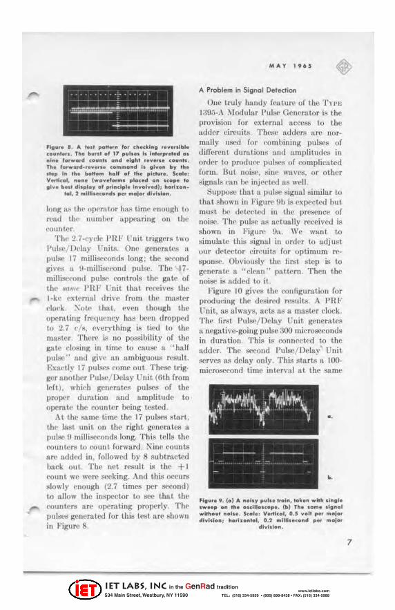
fig ...... II. '.0' p .. n •• " f .. , checkl"g ' .... "11101. co .. ", .... Th. 110 .. ,,1 of 17 p .. bn I. I"'.'pret.d a. "I". 'a.w .. rd (0""'" a"d .Ight ........ c ... "'s. Th. fa.w •• d·r ..... u <a",,,,a"d Is gi ... n flo, ,h. U.p I" ,h. b.It.", h.11 .f Ih. plch .... S •• I" V .. tlc.l, ...... !wo ... ,...... plac.d ... n.p. ,. ,1 ... 110 •• 1 dl'pla, of pri .. dpl. 1 ...... , ... 01 ), ho ...... ·
'01,2 "'1II1 .... nd. p.r "'''I.' dl .. I.I ....
I(IIlg a.ij till' OJl('rll.tor has timl' c-Ilough to rt'aJ tilt, lIumu..'r appearing 011 t ill' ('oullter.
TIll' :!.7·{'y('I(' PHI-' Unit triggers I,wo l'ul!!e/ DI' lay Units. On(' genomtc::! 1\
PUllW 17 miJli:!{'conds long ; til(' ::I('conu gi\'c;! a \I·millige('oud pulse. The 17· millist'('01il1 puiS(' controls the gatt· of tht, 1If1111(' PHI-' l 'nit that. I"l'ccives the I·kl' extNna l drive from thl.' matlter ('Iol.'k. :\"ot(' that, {'veil though the o!X'rlttillg frrquC'llcy hilS 00c1i dropped to 2.7 (' /s, (Ivery thing is tit'tl to the muster TJlt'rr ill 110 PQssibility of th(' gat(' closing in time to cauS(' 11 " half pulse" alld give an ambiguous result. EXIll'tly 17 pulses {'orne out. These trig· ger anuther Pulse/ Delay Unit (6th from left), whit-h generates pulS('s of the pro!X'r durution :lnd ftmpLitude to op('rlll(' the cou nter being tested .
At. the snm(' time thc 17 pulses sttl.rt, the last unit. 011 the right gencratcs a pulse n milliSt"'conds long. This tc.tls the> coullter8 to count forward . ~inc ('ounts arc lidded in . followed by 8 subtmctcd buck out. The net result is thc + I <,ount we were seeking. And thL'! Ol'{'Ur8 Idowly ('nough (2.7 times j)Or !!('(:ond) to nl10w the inspector to sec thuL ilU' c-ou ntl'r8 UN:' opcmting properly . Thl' pulM'!O( g(,lIcrnted for t hi.ij IRst Ilre shuwn in Figure 8.
MAY 1965
A Problem in Signal Detection
Qno truly hundy (cuturr of the Tn'}; l;mfl·A ~lod\Jl:lr l'ul::K' Ct'ncrator is the provision for externul aecess to th .. , adder circuits. Thl'S(} adders are normally uscd for ('ombinillg pulses of diffNont dur..ttiolls :Ind ampli tude::! in order to produ('(' pul~':; of complicated form. But noil><', sinc WlI V('S, or other ~igu:ds ('llil be injl't't.{'(/ as w('11.
SUPJ>Ol'C that a pul&"' signal similar to thut shown ill FiguM' nb is ex!X'ctcd but must Ix> detel'ted ill til(' presence of noise. The pulse [h! lu:tuully received is shown in Figure !Ifl. We wunt to simulate this !lignal in order to udjust our dctector circuits for optimum rt'-
spon:;:('. Obviollsly the tirst step is to generate a "(, lean" pattern . The il the lIoisc is lldded to it.
FiguM' 10 giv(ls thl' l,'()lIfigurtltion for producing the dcsired results. A PH I' rnit, as always, Ilc.:ts o.s!l. master clock. The first. Pulse/DrillY Unit gcnerates II negativc--going pul.sc ;~OO mieroseCOllds in duration . This is conne<'l.cd to t.be adder. The second Pulse/ Deiay' Un it serves as dclay only. This stn rts 11 100-microSC('ond tim(' intf'rvlli at the snme
o .
>.
Fig .... 9. (0) II. ... 1., p .. ". "01 .. , 10k ....... lth ., .. ,1. ow •• p 0 .. ,h. ooelU.u.p •. (b) Th .... "' •• lg .... 1 wi,ho .. ' ... 1 ••• S.ol., V.rtlc.l, O.S .... 11 per "'alar 011 .. 1.1 .. ,,; ho.ho .... I, 0.2 ",1II1 •• c ... et p .. ", .. jar
dl ..... I ....
7
IET LABS, Inc in the GenRad tradition
534 Main Street, Westbury, NY 11590 www.ietlabs.com
TEL: (516) 334-5959 • (800) 899-8438 • FAX: (516) 334-5988

B
GENERAl RADIO fXrERIMENTER
TYPE 1390-8 RANOQN-NOISE
GENERATOR
moment that the 300-microscc.ond pulse begins. After the 1000microsccond interyu l, the third Pulse/ Delay Unit is triggered by the delayed output synchronizing signal. The third uuit gives an output of 100 microseconds, which is switched to the sam£' udder. Finally, a General Radio TYPE 13OO-B Random-Noise Genemtor produces the noiS(> to give the "dirty" s.ignal of Figure 911.
Will the Flip-Flop Work?
Some pulses are so called on ly as Il
matter of courtesy. In a. world limited to finite rise times, t here may be some question about just when It pulse i8 a pulse. A number of circuits such as gnWs, flip-flops, and other logic clements may change their behavior from go to nO-(JO as their input signals become degraded , The effects of deteri· orating risc and fall times are easily eval uated with the TYI't: 139!i-A Modular Pulse Generaklr, fitted out with the TYI>~; 1~9:)..P~ Pulse Shapero
The Pulse Shapcr is basically a makcr of slanting edges. It starts a leading edge upon receiving one input trigger
•
TO AOO(R INP\.IT ON REAR !'liNn.
fig". e 10, The oene.o_ "on of a noi. )' ,,,I ••
• train .
alld starts the trailing edge when the next trigger comes a long. Botb leading and trailing edges arc linear, rather than exponential. Both cun be varied independently in duration within the same decade range. For example, the ..--. leading edge could rise in 17 microseconds aud the trailing edge faJl ill 84, but 17 and 112 microseconds is not a possible co mbination. Trapezoids are readily made, and triangles are formed when the start of the trailing edge is moved up to the end of the leading edge,
Figure 11 ill ustrates the TYPE 1395-A ),lodular Pulse Generator connected to test the efft'Ct of rise time on a circuit. The objective is n pulse with a rise time of 100 nanoseconds, a fall time of 1000 nanoseconds, and a flat top lasting 2 microseconds. The pulse repetition frequency is set at 100 kc/s by tbe Pllf" Unit. (I t should be. noted t hat t he Pulse Shaper draws It good deal more current tban most of the other modules. To prevent eonncction of enough shapers to overload the power supplies, the shapers arc keyed to fit only the three extreme right-ba nd positions.)
IET LABS, Inc in the GenRad tradition
534 Main Street, Westbury, NY 11590 www.ietlabs.com
TEL: (516) 334-5959 • (800) 899-8438 • FAX: (516) 334-5988

-
All example of the output is shown ill Figure 12. Here we!le(' that the objecth·cs in the preceding parugnlph are iudl'f'd mN. This oscillogram was t.uken under open-circuit conditious. The amplitude would be less under loud, since the f;hllper output is basically from II
("u r«'nt sourcc. The Pulse ShupN may be connected to the adders; examples of what this may lead to arc giv('n Inft'r.
An Applkolion 10 Component Telling
Small iron-core inductors, especia lly tho!:\(' wound 011 lossy muterial, 8N' difficult to measure. ;\leasuremellU! made 011 a low-frequency bridgf' are plagued by a very small Q, because wi. is low. With a high-frequency bridge, lossp.s arc high. and so Q is again low.
But consider the equation for the voltage across lUI inductor:
di l! ,. ,~ - + iR
dt ( I )
Ir (/I/dt has a consta nt va lue, and tbe value of e across the coil may be rne88ured, then L is readily found as
," /, - , - (8,,0) (2) oi
where.6. rather than d notation is ch08(' I1 fOr reasons that will be apparent.
The assumption of a oonstant di/<lt is met well if a TnE 1;$95-P:1 Pulse
MAY 1 96 $
Flgu.. II . Th. .. •• 1. P.,I.. Sh.p... • .... "g._
",."1.
Shaper drives a smooth ramp of voltuge into n high resistancl'. Suppose we t ry to set up a ('ollvcnicnt scule - suy I
millivolt developed Ilcross the ind uctor corre~ponds to 10 microhenrYll ill· ductallce.
Let I. in Equu tioll (2) be 10·' and f' be 10·' volta. Solving for ,ll/~ i gives 10""'. Pickillg U rca80nuble but urbitrtlry numbcr for either quantity, suppose we make ,l/ =: b microseconds. Then Doi ""' ;, X 1O"t/ 10-.! ,. ;) X 10·" or o.;} milliamperes. Theil , if we hud a current waveform thllt changed from 0 to 0.5 rnA in ,j microseconds Ilnd impressed tlult current 011 the inductor. we would develop I milli volt for every 10 microhenrys. This cu rren t is easily uchieved if the Pulse Shuper genernlcs a 10-volt amplitude rump in !i microseconds and a 2O,OOO-ohm precis ion resistor is connected between the shaper and the inductor, 8S8bown in Figu", 13.
FI"." . 12. A p.,ls. f.,,,,.d .. .,. Ih. T.,.p. 139$-'3 P"II. Sh"p ... Th. rI •• II",. I. 100 "." ••••• "dll Ih. f.U II ... . I. 1000 "." ••••• "dl . $c.I., Venl •• I, .... ul 6 ... In p.t ",., •• dl",I.I."1 h •• h.nl.l,
1 ",1 ... IK."d p.t ",,,I., dl",IsI.".
9
IET LABS, Inc in the GenRad tradition
534 Main Street, Westbury, NY 11590 www.ietlabs.com
TEL: (516) 334-5959 • (800) 899-8438 • FAX: (516) 334-5988

10
GENE .... l .... 010 EX'EItIhUNTEI.
'1 ... ,. U . ... CCillbra,.d 1.11 .. tar I". I .. d .. dan •• 0' ' ... alll,an_ca,. colt •.
The udullJ int.erconnection of modules would hP u:; in Figure 11, but with diffe~nt sett ings of the knobs. of courne.
Figure 1-1 shows the stt.'P of voltage upplied to the 2O.000-0hm rcsi:;tor. This does indeed rise from 0 to 10 volts in .'j mil'roscconds. The voltage across u sample inductor i:; illustrated ill Figurr' 15. The transients at tht.' leading edge art' flssociuted with stray capadtullce and inductance and soon die out.. From then on, the voltage remains quite steady for ,J microseconds and then drops to zero as the ramp ends and "i/dt changes from u f'onstunt to O. (ACtUlllly, ther(' is 11 l'urront flowing, even though fli/fli is 0, and hence the if( drop in the induf'tm gives a small remaining voltage). The Vll.hlf' of the indut'tor ('uu be read right off the scope gmticulf'. It is ReCIl to ht.. 8:~D
microhenrys.
And Something for the Data.Processing Field
Datn"proc'essing, data .. tm ll ti mitting . Hud data-int.erpreting circuit.;; a nd sys-
Fl ... ,. 14. Volh.,. appll . " b)' , ... T)'p. 1395_P3 ,vl .. Shop •• 10 d.ly . I", Ind .. cto .... letlln, all .... bl)'. S.ol.: V, rtr.at, 5 yolU p .. maio' "'yhlo .. ; "a.hon'al, 1 mlc.o •• eo .. d p.. maja,
dlyllla".
terns ull require input" for test purposes. Except for u. li ttle decadc notation at the hUlll8.n-machine interface, binury is the rule. To those working with bit·s, we offer the Typ~; 1:l9t)-Pli Word Generator.
As the name suggests, the. Word Geuenttor is designed to produ ce sequetwes of 1'1\ lind O's. Tht' ulliit-in cupucity is JI) bit..s. This may bC' shortened !O 14 bits by mctlns of u rearpanel switch . If ~ne 16-bit unit is f'rulcaded with one l-l-bit unit, :ro bits are ma{le IlwtiJabtc. Thus, just two Word Generators can provide !lily number of word lengths based on :l2. :10, or 28. For example, four 7-bit words or six ;,-bit words cou ld be had. For those who prefer one-word-permodule of the bit length they please, any bit ('tlpacity from 2 to Hi CUll 1)1' had through changes in an internal plug-in patch wire.. Any number of modules up to i Cllll be clLScadcd. giving a maximum bit capacity in a TYPE
1395--A Jlain Frnme of 16 X 7 = 112. Another lISC for the Word Generator
is as II. digital scn ler. For cxumple, f1
Word Generator "OllTlc('tcd for II-bit capacity will give one output for cleven inputs when just one hit. flwitch is turned on. Larger ratios an> ilf'hievcd when 11"1" leL one Word Generator dri,'C' unother. The sCI\ler of II, for example,
Fig .. ,. IS. Vallo, . a •• au a .. Ind .. cto, ,.,t.d b)' , .. . a<rang ..... nl I .. Fig .... 13. s.co'., V,ttI.ol, 50 ... lIlIyolh p" ... 010. dlyl ,lo .. ; "ot'10 .. lal, I ... Ie,a o""'_ ... ond p ..... ojar dlyldo .. . On . ... UUyat, .. p ...... ,.
10 ... I ... o .. .... )'II .. d ... ,a .. c ••
IET LABS, Inc in the GenRad tradition
534 Main Street, Westbury, NY 11590 www.ietlabs.com
TEL: (516) 334-5959 • (800) 899-8438 • FAX: (516) 334-5988

o.
,.
fl ....... 16. , .. tt ..... p.odl/.od by tho Typo 13"'." Word Go ..... 'o. cI.h.Lng a Typ. 1395-'2 ,,,1 •• / Dolo., Unit . , .. III". pili ... , .... SO-all ... I."d., l .S_Mlcr'"'''''' d." .. Ho .. , l00_kc bll '0'0. ond
6 .2'-kc .... rd ""0. (0 ) '6_bll w.rd 1111000001100101 (b) 16_bll word 1101010001111101
('ou ld d ri ve Ii !!e<.'Ood Word Generator l'oonected fo r J.t bits, and the t.wo togPlherscalebyaratioofl 1 X 14 - 15-1 ,
Figures IGa and b show two sample _ patterns set on Word Generators. Both
uSC the J(}·bit capacity. The COIlIlC(;tioll of modules is very simple : a PR!" Unit drives the Word Generator, und its output drives a Pulse/ Delay Unit.
One extremely useful feature is that, unlike mnny similar dev ices, the Typ~;
139.')-PO Word Generator is not limited to producing rectangular pulses. I ts output is simply 11. set of t rigger pulses, turned on {lr off ZIt the front.-pa nel· switches. You ean generate a llY pulse shapes you wish by letting these triggers drive other Typ.,; 1395 modules. An
'1"".. 17. A 14-"" w .. d .r '"to .. ha'" .... I ... " . ..... , ..... ., • "I:F u .. lt, • W.,d G ...... ,." o .. d
-" ,h, .. , .. , .. / 0.1 • ., u .. lt • • 81, '0'. 10_h, w .... d ''',. ....... , 714 w.,.h p., ...... d . , .. " .... ,.
11111100001100.
MAY 1965
exa mple is givell in Figure 17, where !l
Word Generator connected for 14-bit capacity triggers other modules to generate a binary pattern of " top hut " pu lses.
Is There on Application for This Pulse'
A devic!e us versatill' as the Tn' .; \:3Y5-A :\'Iodular Pulse Generator will allow the creation of some weird wavefo rms indL'ed. Just ali un example of what Cll n Ix- dune. Wf' point to Figurf' 18. This call on ly lx, dt·scribed as It
witch's ha tsit.ting on a dented pcdcstnl. I t. is produl'oo by a combination of Pulsej Dell1Y Uni ts a nd a Pulse Shuper, all connectt.,>d together via the built-in !lddN circui ts. We have no idea what it might be used for.
DESIGN HIGHLIGHTS OF THE MODULAR PULSE GENERATOR
Earlier in this article. the perfo rmance of the General Radio Tn't:
fl".... II . A.. ..;"mpl. ., 'h. .." .... dl .... ,., .. ", •• thap • • ,h., c .... b ...... d"u d • ., ,h. T., .. . 139S_A M.d .. I • • ,. .. In 0 ...... ' ••. Se.I., V .. llc.I, .11 0 .5 ".It .... m.r., dl","I ... ~ h ....... ,.I , lop, 50 ml ...... o .. d. p • • mor., dl"I.I ... ~ . . .. ,." 100
ml.,o",~ond. ~ "o".m, I ",lIl1t .~ ... d .
11
IET LABS, Inc in the GenRad tradition
534 Main Street, Westbury, NY 11590 www.ietlabs.com
TEL: (516) 334-5959 • (800) 899-8438 • FAX: (516) 334-5988

12
GINflAl I ADI O fX 'I I IMENTI I
!'VUE I I'\.II.$(I ~, Olljl.Y IINIT IIN IT ~ '" ~ ~R ~~ .~~
• - • -
, I' , I' ~ ~Il K~ ~Il ..., "
1217·C;1 was mentioned !lIS n st.urting. point for the THE 1395-A .\Iodu lar Pulse Venerator. To those fu miliur with tht! TYI'~; 1217 in either its B or C ven:;.io lls. it will be interes t ing to notC' thut th(' Type 139.'}-Pl P IU ' Unit ami the TYI'~: 1;m,')..P2 Pu!se/ Dcluy Unit together equal (approximu.te l)' ) OIiC
Tn'''; 1217-C L'nit Pulse Gcn('nltor. The 'I'r ... : 130.').-A :\Iodullir Pulse
Gellerator ('ontains U t'Qmmoll power suppl)' for opemting as many as SC\'I'/l
unit.s. Some modules, such liS the Pu lse Shaper ano the Power Amplifier, ('on· su me II cOllsideruble amount of ('url1'nl. Therefore, the output of tht! PulSt., / IJeluy modules is limited to 20 rnA to ensure th('1"P i.'1 enough power supply cllpzlbilit y to operate allY ;< mix " of modulf'8 that may be cho!ICll .
We ~ha ll now look at somt' of th(' f"ut,urcs and principk'S of operation
'It. \\ .. Pn.nk , ··'mp""",,d I'erforn,,,n,,,, , ..... , 'h" Unit Pu l ... (ienen.IO': · (],"""I RGdi6 8L~"""I"'. I)e... ",Ioe< IIIIH.
'" DlllV(
"V\.$(J KU' ~"
'" ~R ~~,
• -
, I' ~! , 11 ., V "'" oo ,~
loon
of the various ) Ioduill r Pulse Gcnerator units in more dtJtuil.
The Adder System
A sketch, considcmbly simplified , of one adder is shown in Figure IV. Each module that ca ll be conllected to the adders is fitted out with 0. switch. This allows both the posit ive· a nd nega· ti ve--polarity output pulses to be COli·
neeted to either of the two adder busses. Another position allows the positiv~' polari t)' to be cOIllH!c l.cd t.o .I ODEIl ~o 1
Il nd the Ilcgutivc poill rit)' to .\ oo~u ~o 2. The actua l output terminals ar£' t.he source of the signals to the adders. Resistors of lOoo ohm" are provided for buffering.
Rcsis tjv(' udders of this type aN' about the most trouble--free and wideband adders thut can be hnd . However, they do ('"08t in terms of a mpli tudl'. T h£' output signal from the udders will be appreciably les.;; (more than 20 dB less) tha n the output directly fro m
sc. .... l11 CI"CUIT
"It"" 20. al ... k d lolt' .... 0' Ihe T'(~e 1395· " 1 ' JiF U" if .
GAn lQl;~ ,.. "II '''. > __________ ~==== ____ ~:r--' ,. -
IET LABS, Inc in the GenRad tradition
534 Main Street, Westbury, NY 11590 www.ietlabs.com
TEL: (516) 334-5959 • (800) 899-8438 • FAX: (516) 334-5988

I I
r I
an individual module . The TYI'~;
1:j\i5-P4 Power Amplifier h; recommended for brillgillg the signal )pvcl from Iln udder bus up to II higher levcl.
The Type 139S-Pl PRF Unit
A block diagrum of the PH F module is shown in Figure 20. In t.he .; XT
I)lilvt: position, sigllu ls from the ill put umpl ifier trigger the Schmitt circuit. In the IXTERX.U positions, the S('hmitt circuit becomes u free-running oscilhttor. In either CHSC, the grid Clll! be damped by the GATt; circuit to stop operation . The I.Ol:K I" IOX'>' I, illject.8 synchronizing signals in to the Schmi tt circuit to tie its operuting frequency to that of an external source. usuall.\' for frcquency-<iividi ng purpost'S.
:\Iore details of the circuit operotion can be .scell in Figure 21 . :s ote thllt the G,IoT .: IN Ilnd LOCK SIOXA L tubes ( ",O.iB a nd nOSA , respectively) urc normally biased below cutoff. On the GATt; IN terminal , a signal that moves
the grid of "1 0.'3/1 more pOSitive thun about -1.1) volts will cause the product ion of pulsell to cease. The l.Oe l( SIGN,\!, terminal requires abou t 10 volts, peak. (i.c" pulse~ IU volts in amplitUde or sille waves of 7 + "olts, rrns) to start 1"IO .. JA iuto conduction. Once "10.:111 does conduct, it mises the potential Oil timiug capacitor rand causes the grid of S{'hmitL trigger tul~' 1- f02A to riS£' in potcntinl. If the Schmitt circuit WLUI about to fit(' anyway, the voltage rise transmitted through C will make it lire Ill. once. and thus the Schmitt trigger locks ill with t he extermd synchronizing signal.
Capacitor (' is simply II representation of allY of ten different capacitors that arc switched into the circuit. tU!
the frequency mnge is vtiried , Within a ny range. vernier frequency control is achieved by adjustment of RIm. Th{' time eonshl.nt (HIOf + HIO.,]) (' is th(-' chief determinN of the opt'mting frequency.
H50Y
t 150 Y llOi
+1!iOY
-1:;0 Y ."
'" '"
.00
"112
" ,
. -----------,c---i-"~~ YI0311 ~~E)_ ! I "In R12~
- lOY _ 1'1128
"e"'. 21. Th. chl., cI .... II. In 'h. ,It, ",.01 .....
,.,
13
IET LABS, Inc in the GenRad tradition
534 Main Street, Westbury, NY 11590 www.ietlabs.com
TEL: (516) 334-5959 • (800) 899-8438 • FAX: (516) 334-5988

14
OENEIAl IADIO E X "EIIMENTE I
[,l .. ""fyot:!
O[UV(O SYNC Ol./T
r----/ }--;hr----. , OUII'I.IT
Fig ... . 22 . 1110<. dlog"" .. 01 Ih . Typ. 1395_"2 "ul •• 1
Dolo y Unll .
,
SUC > __ -==;;::~:::~~ "
The Type 1395-P2 Pl./I~/Delay Unil
Figure 22 is 11 block Jillgruill of t he Puise/ De luy Unit. The $YNC IN pulse from a PHI" Unit · '>lets" a .set-reset flip-Hop, Thl.' act of !!C Uing it turns 011 OIlC out.put. tube nnJ turnli ofT the other. ill t his wily , both the negative Ilnd positive pulscs are geDcrutcd. At. the $ame time, u cla mp is relcnscd from the Schmit.t circu it . This perm its the UC network to swrt churging to n volt-I;lge level thnt will trigger the Schmitt circuit. The f('leas ing of thl' clump a lso deposits tl controlled [Imount of in itial charge into 1'1l1)Jlcitor C. The more duugc, the SOOner the added ('harge entering thruugh l"(>8is tor If wil1 develop enough voltage to lin' t he Sdlmitt. Therefore. the pI"C-1·htlrge controls the pulse dumtion within the mng<' &'Iected by the value of capllcitor ( '.
As SOUII ,l~ t he SC'hmitt (' irt'uil triggers, it gellerates n UEL.\ n :D ~\'Nl'
OI-TI'I'1" pul!:\('. Thi!l. is Ilvailable tit t he front p'uw[ for :lily [lurpo&'8 requiring time delay (sec, for f'xllmplf' . Figurcfl 2 and a). f.;imu itulloously. a rt'8(.'t puIS(' iJ'l gencratro to rt'turn the flip-lIbp to its original stnte, und 11)(' pulsegCllc rat.ing ~qllenc(' cnds.
ft. i~ secn in Figun' 22 thllt till' output
tubes obtain their power from a v,uillble de supply . This is built illlo the THE l:j95-A _\Iodular Pulse Ccnemtor und Itdjustcd fro IU the front pallel with tI.
knob ffiltrk(.'{1 "" 1... ..... ; 01" CO .\II'O "' t:l'.~1".
The scttillg uf this kr l(,b nllows the c,ut-put pulse to be placed IUlywherc rclnti\'e to ground, from cnti n'l), below ground to cnt irc.ly above.
The Type 1395-P3 Pulse Shoper
The PUiSf' Shaper geller-Hcs iC:lding Il nd trn iliug edges of ", traight-l inc form ruther thull cx pon('iltiul. Thi~ result i~ ucilievc'([ by the dmrgc and dil'chnrge of Ii caplu·itor through l'Olls tlln t-Cllrrcllt SOUrL'C$. Tht'~ SOlll·{'l 'S take the form of grou ndC'i.l-h:l8l' "il ic'OIi Ir:lll s i stor~, whir·h rcceivj' tiJ('i r I'mit t.t'r !'ll rrcntJi from Illrge, nlthough \'ariable. resiJ'l;lors (·011-neeted to thl' + 1:10- amI - 1:,0..\'011 pUWf'r sllpp[ ic~ in thl' mn in framf' .
A circu it diagmm of t he pulsc-shapiug portion of the de" i!'!.' i:; showli in Figure :t:~ . The inpul s tnge ii< :I S('t-rcset ni p-Ilop. A t rigger pul~c' :lpplicd 10 1:\' 1'[·'" I 8tnrl.."l th(' ICllding ('dgcs, a nd II triggcr :lppJil'([ to 1 .... 1'1· ... 2 StM~ till' tmiling edge. If l ht're ill 110 ~ign3 1 at 1"1'\11' 2, t hr flip-flop opera tes ill il.
(·omplemen ting modt' , giv ing s}' mml'tri-
•
-
IET LABS, Inc in the GenRad tradition
534 Main Street, Westbury, NY 11590 www.ietlabs.com
TEL: (516) 334-5959 • (800) 899-8438 • FAX: (516) 334-5988

M.A.Y 1965
.~
r:-r'"'--+-----r-:r;,;;;;;--r-.,---r~·,~ y ~~
r I
I
n. , L ______ --' _ _____ --L_. -,~ y
IJ<lP UT F LIP- I'LOP IJ<l TE Gfi ATO fi
".u •• 23. Th. pl/I .... h .. pl". cI.eul,. .. f Ih. Typ. 1395.'3 'ul •• Sh.p ...
cal operation in the sense of equal time illtt'tvalf! betwccn the start of leading and trailing edges.
The st:tte of the Hip-Hop commUlids either Q.W8 or Q.'104 to conduct. Q3Q8 charges whichever capacitor is selected by the R.\)I,·(a: switch, and QS04 discharges it. Diodes (,R809, r l l."lJo. ('R311 , ( ' R312, (,H304, CHS05, and C RS06 art as various clamps or reference voltages to limit voltage swings and to protect the transistors. Resistors 1l.'j12A , RSIeB, and R,"11·5 determine the emitter currents in Q303 and Q304 a ud thereby act as vernier controls on tbe rise and fall times of the pulse edges.
The output stage is 1I0t shown, since it does not difTer signifi cantly in end results from that of the Pulse/ Delay Unit. Howcver, in order to achieve
lincar operation, it is dcsigned tiS a long-tailed pair with a constant-cu rrent source in the commOIl cathod~lead.
Just how straight the leading and trailing edges art' is a fair question. We are prcpurcd to answer. Most of the engineers who read this article will recall their freshman mechanical-draw· ing class a nd how they were told to check a straight-edgc for straightness.
Fl ...... 24. A. d ..... ".h-all." .f Ih. 1I" .... lty .f !"' • .... es '" Ih . Typ. 1395_'3 'uh. Sh .. , ••. Sc .. I., ... ..tI ... I •• boul4 ..... 111 p •• "'.10. dl ... lllo" , h ... h." ·
101,3 ml ....... o"d. p .. "'''I . ' dl ... hl.".
15
IET LABS, Inc in the GenRad tradition
534 Main Street, Westbury, NY 11590 www.ietlabs.com
TEL: (516) 334-5959 • (800) 899-8438 • FAX: (516) 334-5988

OUUI"l RADIO EXPERIMENTER
Draw a line, turn the straight-edge over, and see how close another line will rail on top of the first one. We have done this in Figure 24. A dual-trace oscilloscope was connected wil h the "A" cha.noel on the positive output terminal of the Pulse Shapero The" B" ('hannel was switched to invert its dis-play and connected to the negative output terminal of the Pulse Shapero This resuJts in two positive-going trapezoidal pulses being displayed on alternaoo channels. They may differ slightly in amplitude because the output potentiometers in the two Pulse Shaper channels arc not identical. Since linearity rather than amplitude is undergoing scrutiny, we felt it would not be cheating to make the display heights equal on the eRO screeo. The two traces were then superimposed as nearly as possible, \\;th the result shown in Figure 24. Remember this figure shows departures from linearity tIOt only in the Pulse Shaper but in the eRO circuits 88 well. We are almost, embarrassed to priut this photograph - it looks like a fraud, but it isn't.
The Type 139S-P4 Power Amplifier
We have not sa id much about this amplifier heretofore. An amplifier jllst isn't as exciting as some of the pulse circuits. Nevertheless, it is worthwhile to point out its main features.
16
Three OUlput. impedances are avuilable: 50 ohms, 93 ohms, and 000 ohms. These impedaoces aJlow match ing to most of the common transmission lines encountered ill pulse and telephone pmcti(:e. Likewise, the input iml>Cdance is variable from 00 ohms to lor,Q ohms permitting the Power Amplifier to terminate I ransmission lines on lhe recc.iving cnd as well as the sending.
The Power Amplifier has been designed as a linear amplifier. This is true even though it will deal with pulses most. of the time. Unlike the pulse amplifiers that nrc really high-powered switches, an amplifier that reproduces pulses of complex shape must be j' hi-fi " in good measure. A photograph similar to that of Figure 2~ was taken in the course of work on this article, but the waveforms showing the input and output from the Power Amplifier SO nearly coincided that. the difference would have vanished in the course of preparing the engravings for printing. It must be confessed that, seen on the oscilloscope, the two traces diverged ill the center by about the width of the trace 0 11 the cathode-ray tube phosphor.
The Power Amplifier employs a unique protective circuit. A small lamp bulb, of the type. usually used in pilot lights, is in series with the + lbO-volt lead, and a secolld lamp ill series with the -150-volt lead. Both of these are mounted ill a ligh tr-tight plastic can, together with a photo resistor . The photoresistor is in a voltage divider arra ngement connected to the grid of a tube that controls an overload relay, 11 either the + L')() or - 150 supply tries to draw exccssi"e current, its lamp glows and changcs the resistance of the pbotoresistor. This alters the grid bias, and the tube switches the relay, turning off the power to the amplifier.
The Power Amplifier is not directcoupled Ilnd will not. retain the de level of the inpllt signal. However, a DC COMPONENT l..'Ontrol makes it possibil' to sh ift the de level of output pulses from at. least. -I.n volts to at least + 1.5 volts with a SO-ohm load , and more with loads of bigher impedance. -
IET LABS, Inc in the GenRad tradition
534 Main Street, Westbury, NY 11590 www.ietlabs.com
TEL: (516) 334-5959 • (800) 899-8438 • FAX: (516) 334-5988
MAY 196 5 ~
r---{~~~}---1:;~~}---1 WORO-(ltJT OELAY G4TE AMPUfl(R
0101.0102 0103,0104 Ol~ 0106
C~K>-_-I
SET I PULSE G[H[II.o.TOfI 0125, 01?6, 01t1
COMMUT.o.TOR
14-16. LOOP. .o.NO CARRY SWITCHES
S917, S 9 18, snl
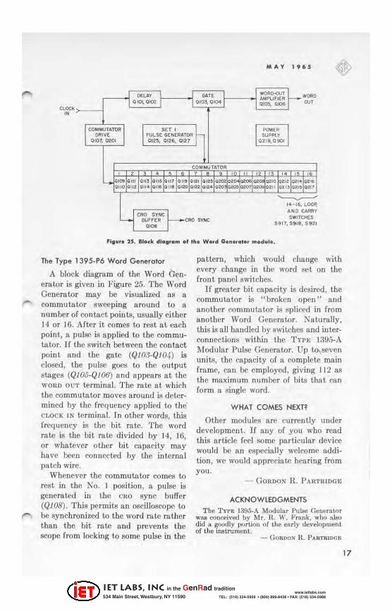
'11"' . 25 . Glock d lol,om 01 Ih. Word G ..... otor mod"I ••
The Type 139S-P6 Word Generator
A block diagram of the Word Gcnerator is given in Figure 25. The Word Generator may be visualized as a
- commutator swc-cping around to a number of contact points, usually either 14 or 16. After it comes to rest at each poin t, a pulse is applied to the commutator. If the switch between the contact point and tbe ga te (QI 03-QJ04) is closed, the pulse goes to the output stages (QI05-Q/06) and appears at the WOUO OUT terminal. Thc rate at which the commutator moves around is determined by the frequency a pplied to the CLOCK IN terminal. 1n other words, this frequency is the bit rate. The word rate is the bit rate dh'ided by 14, 16, or whatever other bit capaci ty may ha ve been connccted by thc internal patch wire.
Whenever the commu tator comes to rest in the t\:o. I position, a pulse is generated in the C liO sync buffer (Q108). This permits an oscilloscope to
,...... be synchronized to the word ra te rather than the bit rate a nd prevents the scope from locking to some pulse in the
pattern, which would change wi lh every change in the word set OD the front panel switches.
If greater bit capacity is desired, the commutator is "broken open" a nd another commu tator is spliced in from another Word Generator. Naturally, this is all handled by switches and interronnections within the Tni': 1395-A i\ Jod ular Pulse Generator. Up ~sevcn un its, the ('apacii,y of a complete main frame can be employed, giving 11 2 118 , . the maximum number of bits that can form a single word.
W HAT COMES NEXH
Other modules a rc currently under developmen t. If any of you who read tills a rticle feel some particular device would be an especially welcome add it ion, we would a ppreciate hraring from you.
- ConooN R. PAH'rlUom:
ACKNOWLEDGMENTS
The TYI'~ 13fJ5-A Modular J>lIb!e Genm'atnr was con«:ived by Mr. n. W. Frank. who also did /I, ~oodly portion of the early dcvelolllllcnt of the matnulIcnt. R I'
- Oo~oos . A~TRll)fl);
17
IET LABS, Inc in the GenRad tradition
534 Main Street, Westbury, NY 11590 www.ietlabs.com
TEL: (516) 334-5959 • (800) 899-8438 • FAX: (516) 334-5988

GE NEIlAl IlA OI O EX PE Il IMENH Il
SP lATIONS
MAIN FRAME ACDEI O" lp,,1 l , .. . I , 0 w I V .... r more, depending: 0 0 DUllloor or modulee use.1 (colltiOUOI.lldy lu:ijtllltabltl ). ADDEIl O" tpul Imp.da"c" 100 iJ lIr 1\l8II ( I()O..!I po~). PULSE DC COMPONENT fl.". " 0 ~ + 20 V (oon tinuous\yadjuiju.ble). Pow,. 1l", .. I.e<! : lOS W 125 V, HIi'! 1.0 235 V, Of
210 to 250 V, 50 to 00 c i s; ,:/,proximntely 250 W, dt' l)\lDding on ctUlU)ti ty nn . type of plug- illll , Auu" . in S"ppli..t , T ypeCAI'-22 POwllr Cord : .pnn: fll_ ; six pa.tch ,-,o rdB - 0 116 each T YPES 274-L ~1B Ilnd 2701-L~1n , two clI,Ch 'I' lPl:;iI 214-1..86 Ilnd 27~-LSR; four blank I:ove. pll.nela; olle 14-conductor module ext.cnsion cable. A •• , .. o.ln Avallab l" All modules in the Tn'l: 1395 lienee ..... Tn.: 1217·1"2 Single-Pulse Trigger, Mo .. "I1"" , I{nck·bencb cabinet. 01""",1"", : Bc.neb model - wid tb IU, h(.'igh t !J}-8, d'lfth 14 ~ iuo.hee (485 by 230 by :i70 m m), over-a! ; .... ek model - panel 19 by 8h jJtchee ~485 by 220 mm), depth hchind patwl I:H4 Inchef! (310 mm). Ne! W, I.tll 'wllho .. 1 mod"ln" u.cuch model, ~l lb (la.2 kg): rack Illodel, 27 lb ( 12.3 kg). Shlppl" S W' ISh t (wU ho ul mod"I .. , : 42 Ib ( 1!1.5 kg).
TYPE 1395-Pl PRF UNIT PULSE flEPfTlTION F_ EQUENCV Inle.noily O,,,,,oled , 2.5 c l e tAl 1,2 ~ Ic . 8 with 12-position 8witch IlIld un(;alibral.ed ~F I:Olltrol. h le.nolly c.."t.oU, d, After (l.(!justrnent for (naxi rn urn llenaitivi ly, 8ille-wilve input of 0.5 V, rillS, required for prf from de to 0 .5 i\'fc / s, ri~ing to 1.5 VJ, fillS, lit 2 :\1c / lI. Input impedance at 0.5 v is a pprox 100 kn shunted by SO pF. Nnll-6iulIsOwlI.I lIigual requ irC9 a nega.t.ive-r;oing at\.lv (If I V.
INPUT AND OUTP UT StONAlS SyllC 0 .. 1 Pul ... : At leo.sL 10 V, poeilive, wi th dllratillil betweell 75 and 150 DII (nominally 100 lUI) ! rise t ime appro)! 25 1111 lind l,Iu lput impootUlC6 approx as fl. Lod! SII"ol , rHF U uitoperll.tlllg at I kc a CM be looked to Ii. fn, .. q w:lIIcy of 10 ke s by 10-" posi tive pul_ " 'ith 100-111 dUra tion or with u aine ..... ave of 7 V, r mll. Required pl.I5itive-
l)u1se amplitude increaeea 00 about 12 V to ock the 1 kc / s to s frequency of 2 ke / 8,
Ga' . l"p"l, A potential more J'I(l!Iitive thall - I V at t his termiual SOOIlIl t he generation of IIYNC OUT pulses. Slablllly , Prl jitter ill. 0.05% when the. PRF Unit iB opera ted from the power l upply In the T yPE 1395-1. mwn fram e.
18
OENEI AL Pow .. c..n,,,,,,plla .. , + 150 V a t 25 rnA: - 150 V AtSmA; + 15V atS mA : 6.3 V, OO C/ 8, 1 A.
Ace,no.lu 5 .. ppUed , SO: pb.tch curda - Olle each TYPl:1I 2io1-L~'\Il nnd 2i-l- L:\I R , t " 'O euch 'l'fI'P-1I 2H- I .. S H uud 274- LSrt j ~wo insula ted pluglS, one e8ch Typ~:s. 274-DB I i~lld 274-D132... Acu .. o,'" Avallabl" TY i'l! 12li- J>2 Single-1:>U1se T r igger, ot her TnI': 1 ;~\'I5 modulC9. Nt l W, llhl: H~ lb (0 .7 kg). Shlppl"S W' lshl ' 4 !1 lb (2.1 kg).
TYPE 1395-P2 PULSE/DelAY UNIT , .. 1 .. a"d D'loy D".ollon., 100 lIS to I I'll I«:CUra te to ±5 % Qf reading Or ± 2% of fill scale, or ±36 nil, whiellever ill grc:ater. ,." .. R'petltlo" F-.q"'ncy: Detcmlilll.>d by input ~VIIC I!ignul - r ll.nge de to 2..1 :\Ie. s . Input signllis ellll be ' ''fldOlllly spnced if 8CJlll.ratetl by Ilt least ·100 1111. Ill .. o .. d Foil Tim"' 1_ thall 15 ns with 50·0 103<1. On high-volt{lge output (20 V into I kn). trnnsi tiotl!! llre tYJlicaUy 80 flS + 2 na IpF of lond eapaei tJUl t1l. 0 .. 1" 1 VolioS" ± 20 V pull!!ell into l-kO iutetna.l IQiId impednnce ( ± I V inul SO-flluad ). l"pUI 5y"c R"' .. ltI . ...... h , POliitive-glliog pul&t:, 10 to 20 V, wi th i &- to l50-ns duration. D,layed O"'p"l, i'08.itive puhle of :It lcast 10· V Il.llIplitude a lld ib- to 150-011 durlltion. Output impednnce appro" 125 fl. Time betweeo SY.'l:C 1.'1: and In :1. OUT puiBc8 set hy !,UUlE DU" .<.T(Ollo.·
!!Outlot Slablllty. Puille-dnr:1.tion jitter ill 0.05% when Pul8e / Delay Unit ill operAted in the TypE 1395-A main frame. Pow .. eo",,,mptlo .. , + 150 V li t 15 mA ; - 150 V at 30 rnA ; 0.3 V, 00 e/s, 0.7 A; 11 .3 v , 60 C/ B, 1.3 A; +15 V !I t 5 mA ; () to + 20 V, variable, Ilt 25 mA . A • • n,o.l .. Suppllood: "'ive pntch cOrdll - t .... D each Tyl't;.S 274-I..SB and 2i4-LS Il., o lle TypE 274- 1,MR j 1. .... 0 insulated plul;II, one ellch T YPES 214_DBI and 27·14I)B2: N, I W, lshl : I ~ Ib (0.8 kg). Shlppl"l1 W,lshl:" !4 lb (2.2 kg).
TYPE 1395-P3 PULSE S~IAPER INPUT PUlSES: 10 V to 2Q V in Rmpl it.ude Itnd 75 liS mill imum d Ufll tioll .
OUTPUT 'UlSES OU.OIlOh : Time OOLween pul8ea at I N I Ilild IN 2 plu!! du rlltion of trailing edge. _I .. 0 .......... li"'n , 100 1111 to) 10 ms ill live dooade railgCOJ, ± 10% of fllllllCllle , from the 0 00 100% points. Rise 8.l1d fa ll t imet! CIUI be adjusted, independcotl,r by !!CpBrate c~n~ols or simul tanooU8ly by a IImgle control , wlthm t he same decade r ange. T o obtain timet! 1_ t blUl 11. few hundred na l1 086eOnds, outpu t mU8t he tenninated in 50 to 100 D.
IET LABS, Inc in the GenRad tradition
534 Main Street, Westbury, NY 11590 www.ietlabs.com
TEL: (516) 334-5959 • (800) 899-8438 • FAX: (516) 334-5988

l1n ... d l y: A lending !lr tr.l.ilill~ edl,'ll voll"g!' r.( !) mnking " t r lll\Jl;ition "f ,,: volta in time 7' lI'ill noL III lillY timll- I liepllrt froll! the
t"fIUnlion c .. ~,I (0 $ I $ 1') by mort! th:m
0. 1 "'. \ typiclIlly better thlln 0 .05 E). T he fll3t.esl trllnsitions will not yield thiq performance lInll~ olltpulll 111'6 te rmina ted in 50 to 100 n. Vollog.: ±20-V puJses iutn l_kO internal load impedance (±1 V illto 50-tl load ). G£NUAl
Po .... . r Conu.mpl;on: +150 V ut -15 luA ; - 150 V at 55 mA; li.~ V. 00 cis, 0 .15 A; 0.3 V, 1;(1 e '5, 0 .11 A: 0 t(1 + 20 V, vnriuble, ut ao mAo Au . no, j., Supplied , F'ive pnlch eQr(\l! - two ellch TYf't:s 274-1.8» Hil t! 2i~-LS H , one TYl'~ 274-LMR ; two insu1lited piUgfJ, 01111- Cl\{!h TYPES 274-D111 lind 2H.D I32. N. I W.Ighl : I ~ lb (0.8 kg). SII lpp' ng W.l lht: 4. ~ 1 lb (2.2 tg ),
TYPE 1395-P4 POWER AMPLIFIER O"tp"l lmpecianc., : 50, 'JJ, uut! 000 11, "ll ± IO%. O .. ln" 20, 20, l'Ild 26 dB, rcsvectiveiy, lit t he above imped anCt!8 ll.nd with lU!Ltclu.-d louds, !l.1I ±2 dn: P"b . O"lp" t V"ltol.: ±20 V pilisee ill tv 50-II lond \\'ith 10% duty cycle. LIlTg1!r duty eyrlcs mlly be UlIed at lower outpu t levels. Itl •• ond foil Thnu: Less than 60 ns on a ll trallsitions with II. OO-n load aud llelcdor switch IItlt fo r 5O-n impcdaut'e. S;n.- w"v. Ampllfl.r: Po"cr ou tput into 50- I&ml 93-fI loads is at le!U!t 2.5 "" (3% distortion typiclll ): into 600-flload. lit lel\81 1.5 "" (distortion, 1.5% typical). fr.q"ency Ru pon .. : UOII"II less than ~ dB at 20 c , s And 5 ~ I c s with 50- and \la-n loaW! , 2O e , 1I Ilud 1.5 Me. II with (i()()..Olond. D. L.ntz De boselil1c of pul8ell nnd centerli ne of lIine "'Ilves can be illovrd at leMt ± 1.5 V. de with 50-0 load&, lind more with higher Impedance loads. Inp" l hnpedon .. : Adjuatuble frmn 50 ttl HmO II, shunted by appro); 45 p F. Po ...... Con, ,,mpl ion : + lfiO V a t ! fjO In.o\, ilia);, - IOOVat IOOmA, max; n.;J V, tOO 0 s, 2.2A ; tI.a V, 60 c II, 1.9 A.
MA Y 196 $
A,,,.no.lu S .. pp lld : Four pllUlh cords - one enc lL Tnt:s. 2i4-L~IB . 2i4-Ll\I ll . 274-L811. anti 274-LSH.; two ill1)ulllted plug:'!. one ellch Tn!!.s 274-08 1 and 274-DIl2. Nel Weilht : 21b (1 kg). Sh lppinll W. lghl : 5 Ib (2.;,1 kg).
TYPE 1395-P6 W ORD GENERATOR INPUT P .. I'e It' pellti .. " f ....... " .y: Ue 1.0 2.5 -'Ie/ll, externally controlled by Tv".; L395-P I PRF Unit (or similar unit )_ T.lllle. _p" t .. R' q"irem' nt" 111- to to-V IJoOIIitivegoing pulsetl of 75- W 150-U8 duru,tjoll_ ~uare "RVes 0011 be u9('11 IIbo\'e iO kl: II: lIi lle waves, Ilbove 500 kc / s. Impedan.e: 100 hI 600 Il, depending upon trigger II.lIlpli!.ml,·.
OUTPUTS Wo.d 0 "'1: 10- 1.<1 2fl-\ I l\lIIi~ive-going pul_ of if;. ~ ... lao-us dnrll.tion. Output impedance I&!,prox 150 fll but IcrminHtiOIl ill 500 to 1000 r.t 19 ~ommem ed. P .. " . ... : ~t h~' front.-pH!lel Bwit{!hC'fl. Choice of IG-hit Ill' l.t-hit Cft llacit,l by rell.r-ptl ltel Bwitch . One call acbicve capac, tiel! otbet than Hand 16 by motiifictllion of internll! wiring. I nterconnection of up to Beven unil.!! provided by the T n!: 1 ;~9;i-A ,\tlllll Frnme. Ol<lIIo",,,p. Sync: Il.ectangulllr JlULse of 2-V min limplitude !Lnd duration equal 10 period c,f dril'ing-l\igOll1 prr. Oecul'll IlI)Prox 50 II~ hefore I.he SWitch ! 1 output pulse, whether vr not Ihe ""'itch ill 0 11.
OENERAL Po .... . . c:..n, .. mpllon : +15 V at [, iliA: 6.a V, M c18, 0.8 A. Ace , .. o.I., S"ppll"', Five paWl cortl9 - olle CHell 'rYl'Ie:S 2i4- LSB, 274-Lsn . '274-LMU, 274-LM R , and 274-LLI1 ; two in8ul ll.ted plugJI , nne each TTI'),'!; 274-I)BI and 271\-0 82. N. t Weill". : 214 Ib (1.2 kg). Shlppl"1I Wel,ht : 5'1 1b (2.5 kg ).
TYPE 1395-P7 SKelETON FRAME A blllilk module ~ui tnble fot mounting the
comptmcnts of a user..qCfligned circuit. Dlm. n. l"ns: Width 21" , height 81~ . depth 5 in (55,220, l aO mm), over-all. N. , W. ll h! : '4 Ib (0 .3 kg ). Sh ipping Weight : 3'1 1h (1.6 kg).
Description Price
HI USA
1395-9801 1395-98 11 1395-9601 1395-9602 1395-9603 1395-9604 1395-9606 1393-9607
Typ. 139S. A M"d"I"r P"I • • Gent/olo"Bench Mod.1 Type 1395. A M"dut ... P"I .. G. nt/oto" Ro'k Mod.1 Typ. 1395_PI PU: U"il Typ. 139$-P2 P"ln/D. loy Unit Typ. 1395-P3 "~I •• Sho p • • Typ. 1395_ P4 Po .... . . Amp"f1 .. Typ. 1395 · P6 Wo.d G. n . ... lo. Typ. 1395 _1"7 Shlet"n f.om e
$$00,00 500.00 ISO , OO 16S.aO 37$,00 1$0,00 400.00 12.00
19
IET LABS, Inc in the GenRad tradition
534 Main Street, Westbury, NY 11590 www.ietlabs.com
TEL: (516) 334-5959 • (800) 899-8438 • FAX: (516) 334-5988

~ GENERAL RADIO EXPERIMENTER
20
FI"" •• 1. 'an,' yl •• of ,II. Typ. 1162.AR1C Coli .. ,", Decade Fr.q .. ency Synlhuln. with ptog .... "mo .. '. d.cod ... 5 •• comp'e" 1I.llnl of mod,l, on POI' 24.
REMOTE PROGRAMMING FOR GR SYNTHESIZERS
When the first Iwo GR synthesizers were described in the September 1964 issue, provision for remole frequency seledion was mentioned only briefly. The ROI-] Remole Digit-Inser. tion Unit is now in production and is described in this orticle. One of the outstanding charaderistics of the GR synmelilers is their modulor design. This permits iniliol choice of re50lution to satisfy 0 particular need while retaining full flexibility fOf future expansion. In a Iogicol extension of the modulor concept, remote programming is offered flOW as on option.
filII •• 2. View of Ihe Typ. 1160-1101-1 OlgllIn " "\on Unll. Th. fit", and ..... ,.1. plug con b .
.een ,..oJe.,;nl ' ... m th . .. or.
The Tn>K I I 6Q..-RD I-I Digit-I nse rtion Unit (Figure 2), together with its filter und mat rix plug and remote cabling, brings to the OR synthesizer line com plele or partial remole frequency programming at the user's option. The ROI-l can be used in all digit stations in the TYI>!'; 1161-A and TYI>E 1162·A Synthesizers, and in all but the l-:\Ic station in the TYPE 1163-A. In all cases, it is directly and qu ickly interchangeable with the D1-1 unit. Control can easily be transferred digit by digit from remote to manual, lending additional tiexibili ty.
During the development of the GR synthesizers, it became apparen t that these generators, by their very nature, arc more readily programmed t han are conventional signal sources. While a necessity ill certain applications, a programming capability obviously adds to the pric.'e and complexity of the instrument for users not requiring it Hence, remote programming is offered as an option.
In the design of the plug-in DigitInsertion Units, space was provided for the additional elements necessary
IET LABS, Inc in the GenRad tradition
534 Main Street, Westbury, NY 11590 www.ietlabs.com
TEL: (516) 334-5959 • (800) 899-8438 • FAX: (516) 334-5988

DIAL LIGtiT COHTROL
DIGIT PHASE
DETECTOR
VIDEO AMPLIFIER
MA Y 1965
f l,u •• 3. Block d lo ,rom of 'h. Rot.! R.mo,. DI,i' .lnu tfio n Un it.
for remote operatiou. 1l was also COIl
sidered desirable that a programmnble module be capable of mallunl operation. Taking full advantage of the unique packaging of the DI units. the RDI-J is so design(.>(1 that it uses a maximum of ('ommon parts with the DI-l. The HDI-J dial hus the lIslL!ll ten positions, o to V, lind an II th posit ion marked It,
ill which frequency selection is made by <"ontilrt closure on the remote wires. [f the dial is moved from the Ie
position, 1he manual selection overrides the remotely programmed information.
As call be secn in the block diagram in Figure 3, selectioll of a digit ill the RDI-\ is accomplished by the chnnge of frequency in the so-called digit oscillator, which for each setting is locked to a ';picket fence" of standard frcquen-
des from 3.0 to 3.9 ':\Icjs in 100-kc steps. Capacitors ill the digi\-oscillaLor cirruit are switched by low-loss, rf-type reed relays. The recd driver coils are energized from the internal supply but. ('fill also be operated from Ull external supply. To select a particular digit. on€' hus merely to establish connection between the designated d igit wire and the common wir€'.
The reed relays arc directly [lSi;Qcinted with the rf circuitry in the digit o.~ri1lator, and capacitive coupling exists to the driver coils. T o reduct' rf voltages all the remote wiring. nn internal two-section filter is used, which reduces the rf level to approxima tel.v .'iO /lV. In addition. the cable supplied hus a groul.lded shield to prevent nFI.
Thc compollen ts of this filt.er are housed
21
IET LABS, Inc in the GenRad tradition
534 Main Street, Westbury, NY 11590 www.ietlabs.com
TEL: (516) 334-5959 • (800) 899-8438 • FAX: (516) 334-5988

~ GENERAL IADIO EXPERIMENTER
22
in ft timull. separate, plug-ill shield (·ngaging fl COllllector that protrudes from the rear of the RDI (Figure 2). Thi~ filter plug ILlw contains the diode matrix that converts from an internal biquinary eooe to it 100iine code. The unit, can be remotely progmmmed in either code; the tilter plug is normally wired for IO-line. but. removal of 011{' jumper wire f'Ollvcrts it t.o th(' biquinary code. In the InttN modt' of operation. the digit 9 is prodUCL><i with no ('xt/'rnnl closures; 8, 7. (i, .j
are scICt'l(·J by l'Ollllcctioll of thf' appropriate wire to tht· ('ommon wire. The lower digits 4, 3, 2, I, 0 tll"(' obtained with the &l.nw c]osu!'CJ.I U8('d already for the higlwr digits but with the additional ('Iosure of II. range (or J.! hift) wire to common. The 8 wire produ('C's digit :1 when cOIllll'ctf'll to eommon, 7 selects digit 2, and so on. In tiH' IO-lint' mode, where onc wiIT' ('orresIJonds to each digit, the digit 9 is a lso scleded with no closures. The 12 leads in the cable supplied arc the maximum net!(led (IO-Iine with extcrn:11 powpr).
A dc\·ice is suitable for direct connection to thf> RDr-I's if it provideR either
fl.",. ... O .. Ulo.ra... .ha .... I... • .... lteM... II ....
' ... 'utl.
mechani(:ul or eiedri(:ll.i contact closure in the lO-line or biquinary form and maintuins continuous closure us long as II particular frequency setting is uesired. If u transistor :>witch is used. voltage drop must lIot exceed 0.5 volt for curI'Cllts from 2 .. ~ to 9 rnA. The internal supply places t he ('om mOll lead at ground potential. whereas t hl' open wireA arc a t + 18 \'olts with respect to grou nu . With un t'xternai supply of 18 volt.'!, these potentials can he moved up to +.')() nud +:12 volts (comIllon) und to -32 and -.iO (common ). Vollages inside this range arc acceptable: 18 volt.'! urc rf'quired to operate the I'(' lays, and thl:' common must be ncgativc. For operation with externa l supply. two jumper wiN'S a re remon'd in the RDI-1. This should faciJitah'
IET LABS, Inc in the GenRad tradition
534 Main Street, Westbury, NY 11590 www.ietlabs.com
TEL: (516) 334-5959 • (800) 899-8438 • FAX: (516) 334-5988

direct tie-in with existing equipmen t , purtil'ulorly wit h t ra nsistor-switch output.
.\IUllY appliclitions will require the programm ing of :>Yllthcsilwr fIT'quellcies by digit:1I l'quipmcnt. ill bill!lrYeoded decimals. Storag{' may be t'ulll'd for if entry is ill &!r ifl l rnthf'f th;\n in paralll'l form. Suitable eOll versioll t'quipmt'llt is 1I1ldf'r cOllsidenlt iOIl .
T he rt.'Cd relays combim' simplieit.y of circu itry with sJX.'t'd suflil'icnt fo r most nJ)plicatioll s. Switching ti m(' i ~
less llwn 2 millisecond li. This is th(' t ime intervul betwecn tilt' ex t.f'rn ll l ('011-tnct. l'IOf;urc and the presenCf' of t he
M A Y 196 5 ~
Iwwly I'(" lc('tA.'£I freqllclley . Thc artual trans ition fro m Dill' frrqucllcy to UIl
othf'r is appreeiably fnstcr as Cli n Ix$Cell ill Figure 'I . wh ic'h S.hOWiO a switt.: /t from n.O!)2·' ke/ !:! to 2.0:{(j 1 kel so T he heavy trae{' is t hc volllige ucross the cxterllul t'Ollttu:t (of the first digit) . The lower portion show~ I'losed con tad (0 \'oits) ulld the upper portioll opl'n t'OlltuCt. Timt> 8('9.lc i!S 2 mli / em.
The eapabilit.y of fns t , remote freqllCJl(:Y selection !ldd~ another dimellsion of versntilily I.() til(' C R .;yntht'sizer lillC, thu~ openi ng up a new rnngf' of upplicatiolls.
(; . H . LOHlU;1l
SPIClflCATION
S .. ltchl ... SpHCI : 2 nil! or 1_. Cod. , IO-lin~ .1r biquinHr .... (I'ontl.t'! <:I,.",rt.,). '0 .... ' Inu'nH.1 supply, provisiun (or exlern,,1 IlUllply 18 V, U mA o
N •• Woight: 111l lb (0 .7 kg). Inlltrument speciCicati'1IIs o( Lhe Tl'pgl! IHiI _A, I IU2-A , nnd 116:J.-A " 'main unchanged if RDI_\'@ are sui:.8tiwted (Or DI-I units.
Caw/og .\ ' umhr.r f)e3Cf1plum
Price j" USA
T1'P. 1160_ RDI _1 Dilli l- I ..... ,I.II U .. II/Romo •• Of
",0""01 COfIlroll, j",l .. ding Fil t ... PIUII
HOOK-UP CABLE FOR RDI- I
$535.60
A SPCCilll, I ~-colldu ctor , flhielded n dJl1' is t('f'ommellded for cOlilledinn of t.he f1-pin fi lter-plug to rt.' n1otc equipment. One flO-foot roll of cubic is furnished with each synthesizer ('(11) -
Illinjug all H D I- I uni t but i.; lIot su pplied with un individuully pu rchaSt..'<l n 01-1. Add itional rtO-foot lengths ('UII be ordered SI' parnt('ly.
Catalog Ntl~r
1160-9650
Not Woillhl: 2 1'1 Ih ( 1.2 kg).
fleMripli(m
Hoo •• Up Cabl . for ROI· l, 50 foot
Price in US."
$ 15.00
23
IET LABS, Inc in the GenRad tradition
534 Main Street, Westbury, NY 11590 www.ietlabs.com
TEL: (516) 334-5959 • (800) 899-8438 • FAX: (516) 334-5988

GENEItAl ItAOIO EXI'EItIMENTEIt
COMPLETE SYNTHESIZERS FOR PROGRAMMABLE OPERATION
Tilt· '1'"".: 116 1-A (0 to 100 kc/ s) with HDI un its. For synthc:s.izcr spet'i. !Iud T\I>t: ll{i2-t\ (0 to 1 i\1c/s) Syn- fications, sec the " :.\7J(.'TiIllClIll'r for t.hcsiz(·rs 1Irt' now nvn iln bll' equipped September 1H6·1.
TYPE 1162·A COHERENT DECADE FREQUENCY SYNTHESIZER 0 to 1 Me/s Culwroled Digita
('alalOj/ Ihrod<o OtlC6llu SlIIl,Uut Sfep />riu ,'",'~r 7'_ t'niu Includro 0",. + CA D" (J)iVlI~ Onlll) in USA
4-I I 62-9$V 1162.AIt7C 7 ltD! Un;" + CAD , 9 0.1 e/ _ $6195.00 , '62-9$26 1161:·AIt6C 6 ltD! UN" + CAD , • , e/ _ 5670.00 ',62-9.s2.S 1161:. AIt5C 5 ltD! Uf'IIlI + CAD , , '0 e/ _ 5 145.00 1162-9524 1161:-A.4C 4 1t01 UNII + CAD • , 100 e/ . 4620.00 1162-9523 1161:_AIt3C 3 ItDI Unlit + CAD 3 , I kc/ . 4095.00 1162-9507 1161:_A.7 7 ltD! UniT> , 0.1 e/ _ 5695.00 1162-9506 1162_AU 6 RDI Uf'II" , I el l 5170.00 1162-9.505 1162_AIt5 5 RD! Unl" , 10 e/ _ 4645.00 1162-9.504 1162-AIt4 4 ROI Uni" • 100 e/ _ 411:0.00 1162-9503 1I61.A1t3 3 ROI Unlll 3 1 kcl l 3595.00
TYPE 1161-A COHERENT DECADE FREQUENCY SYNTHESIZER 0 to 100 kc/s. CalibrtUed Digit« ,
• f'uWQfI /krod" D=d .. SmtlU,M ,';tep Pria .\lwI/Hor T"". "m'Lt Includtd O..ty + CA l)· (I:>!'gil, On/l/ ) In eSA
1161-9521 1161_A.7C 7 ID! U"'10 + CAD , 9 0.01 e/ . $6055.00 , 161-9526 1161_A1t6C 6 ID! U"'h + CAD , • 0.1 e/ I 5530.00 1161-9525 1161 _A.5C 5 101 Unit. + CAD , , 1.0 e/ _ 5005.00 116'-9n4 1161_AUC 4 ItDI U ... " + CAD • , '0 _I_ 44'0.00 1161-9523 1161_AIt3C 3 RDI Unlh + CAD 3 , 100 e/ _ 3955.00 1161-9507 1161_AI7 7 101 Un;" , 0.01 e/ _ 5$55.00 11 61 - 9506 1161_AIt6 6 RD! Unit. , 0.1 e/ _ 5030.00 1161 - 9505 1161-AI5 5 ROI Unllo , 1.0 _I_ 4505.00 1161-9SOA !16I-AU A RD! Unit. • '0 e/ . 3910.00 1161-9503 1I61 -A It3 3 RD! !Jnih 3 100 e/ _ 34SS.00
-1),,,,,,, _d,"II. If ('AD", .",Jib .. l...! "' len" , oIlhe .Iel> deo:&d .... 1 ,_ ODe II,.".., ....",Iiea .. , lieu'" un be added. lI. S. 1·.ten~ N(,I. 2.M8.41'>7. "._u .. ppl><>d 'nr.
NEW GRO REPRESEIiITATIVE FOR NORWAY We 1l1H10 Unl;e the appointment of
the Norwegian firm of Gustav A. Ring A/S as exclusive Gcnera l Rudio Company (Over8ClLs) representative for Norway, succeeding tbe fi rm of MaskinAktiesclskapcl Zeta, wbo have rcprc-8entoo us ill that country since 1948. Effective in February, 1965, Gusltw A. Ring A/ B took over these responsibilities, a nd is now directly serving our
customers in Norway with competent tecbniclllllssistanoo.
All inquiries, whcther technical or commercial, concerning General Rudio products should be addressed to:
Gustav A. Ring " IS SJlrkedalsvcicn ;13
Oslo 3, Norway Tel 4(j f)ij 90 • Telex (j234 • GAIUNO
,0':"" ...
IET LABS, Inc in the GenRad tradition
534 Main Street, Westbury, NY 11590 www.ietlabs.com
TEL: (516) 334-5959 • (800) 899-8438 • FAX: (516) 334-5988